EP3692932A1 - Appareil multifonction - Google Patents
Appareil multifonction Download PDFInfo
- Publication number
- EP3692932A1 EP3692932A1 EP20155929.1A EP20155929A EP3692932A1 EP 3692932 A1 EP3692932 A1 EP 3692932A1 EP 20155929 A EP20155929 A EP 20155929A EP 3692932 A1 EP3692932 A1 EP 3692932A1
- Authority
- EP
- European Patent Office
- Prior art keywords
- positioning
- acetabular
- milling
- configuration
- handling body
- Prior art date
- Legal status (The legal status is an assumption and is not a legal conclusion. Google has not performed a legal analysis and makes no representation as to the accuracy of the status listed.)
- Withdrawn
Links
- 238000003801 milling Methods 0.000 claims abstract description 92
- 238000001356 surgical procedure Methods 0.000 claims abstract description 33
- 230000005540 biological transmission Effects 0.000 claims description 87
- 230000008878 coupling Effects 0.000 claims description 34
- 238000010168 coupling process Methods 0.000 claims description 34
- 238000005859 coupling reaction Methods 0.000 claims description 34
- 230000033001 locomotion Effects 0.000 claims description 14
- 238000000034 method Methods 0.000 claims description 13
- 230000013011 mating Effects 0.000 claims description 8
- 230000000774 hypoallergenic effect Effects 0.000 claims description 5
- 239000007769 metal material Substances 0.000 claims description 4
- 230000000284 resting effect Effects 0.000 claims description 4
- RTAQQCXQSZGOHL-UHFFFAOYSA-N Titanium Chemical compound [Ti] RTAQQCXQSZGOHL-UHFFFAOYSA-N 0.000 claims description 3
- 230000004913 activation Effects 0.000 claims description 3
- 239000010936 titanium Substances 0.000 claims description 3
- 229910052719 titanium Inorganic materials 0.000 claims description 3
- 210000001624 hip Anatomy 0.000 description 18
- 230000007246 mechanism Effects 0.000 description 5
- 230000001954 sterilising effect Effects 0.000 description 4
- 238000004659 sterilization and disinfection Methods 0.000 description 4
- 230000009471 action Effects 0.000 description 3
- 239000000463 material Substances 0.000 description 3
- 230000008569 process Effects 0.000 description 3
- 238000005406 washing Methods 0.000 description 3
- 206010020751 Hypersensitivity Diseases 0.000 description 2
- PXHVJJICTQNCMI-UHFFFAOYSA-N Nickel Chemical compound [Ni] PXHVJJICTQNCMI-UHFFFAOYSA-N 0.000 description 2
- 229910000831 Steel Inorganic materials 0.000 description 2
- 238000009833 condensation Methods 0.000 description 2
- 230000005494 condensation Effects 0.000 description 2
- 230000006866 deterioration Effects 0.000 description 2
- 239000007943 implant Substances 0.000 description 2
- 238000012986 modification Methods 0.000 description 2
- 230000004048 modification Effects 0.000 description 2
- -1 nickel and chromium Chemical class 0.000 description 2
- 239000010959 steel Substances 0.000 description 2
- ZCYVEMRRCGMTRW-UHFFFAOYSA-N 7553-56-2 Chemical compound [I] ZCYVEMRRCGMTRW-UHFFFAOYSA-N 0.000 description 1
- VYZAMTAEIAYCRO-UHFFFAOYSA-N Chromium Chemical compound [Cr] VYZAMTAEIAYCRO-UHFFFAOYSA-N 0.000 description 1
- 210000000588 acetabulum Anatomy 0.000 description 1
- 238000007792 addition Methods 0.000 description 1
- 230000000172 allergic effect Effects 0.000 description 1
- 230000007815 allergy Effects 0.000 description 1
- 238000004873 anchoring Methods 0.000 description 1
- 208000010668 atopic eczema Diseases 0.000 description 1
- 239000000560 biocompatible material Substances 0.000 description 1
- 230000037396 body weight Effects 0.000 description 1
- 239000004568 cement Substances 0.000 description 1
- 239000013043 chemical agent Substances 0.000 description 1
- 238000006243 chemical reaction Methods 0.000 description 1
- 229910052804 chromium Inorganic materials 0.000 description 1
- 239000011651 chromium Substances 0.000 description 1
- 238000005352 clarification Methods 0.000 description 1
- 230000001419 dependent effect Effects 0.000 description 1
- 239000000645 desinfectant Substances 0.000 description 1
- 238000003780 insertion Methods 0.000 description 1
- 230000037431 insertion Effects 0.000 description 1
- 229910052740 iodine Inorganic materials 0.000 description 1
- 239000011630 iodine Substances 0.000 description 1
- 239000000696 magnetic material Substances 0.000 description 1
- 230000007257 malfunction Effects 0.000 description 1
- 238000004519 manufacturing process Methods 0.000 description 1
- 229910052751 metal Inorganic materials 0.000 description 1
- 239000002184 metal Substances 0.000 description 1
- 150000002739 metals Chemical class 0.000 description 1
- 229910052759 nickel Inorganic materials 0.000 description 1
- 230000007170 pathology Effects 0.000 description 1
- 230000002980 postoperative effect Effects 0.000 description 1
Images





Classifications
-
- A—HUMAN NECESSITIES
- A61—MEDICAL OR VETERINARY SCIENCE; HYGIENE
- A61B—DIAGNOSIS; SURGERY; IDENTIFICATION
- A61B17/00—Surgical instruments, devices or methods
- A61B17/16—Instruments for performing osteoclasis; Drills or chisels for bones; Trepans
- A61B17/1662—Instruments for performing osteoclasis; Drills or chisels for bones; Trepans for particular parts of the body
- A61B17/1664—Instruments for performing osteoclasis; Drills or chisels for bones; Trepans for particular parts of the body for the hip
- A61B17/1666—Instruments for performing osteoclasis; Drills or chisels for bones; Trepans for particular parts of the body for the hip for the acetabulum
-
- A—HUMAN NECESSITIES
- A61—MEDICAL OR VETERINARY SCIENCE; HYGIENE
- A61B—DIAGNOSIS; SURGERY; IDENTIFICATION
- A61B17/00—Surgical instruments, devices or methods
- A61B17/16—Instruments for performing osteoclasis; Drills or chisels for bones; Trepans
- A61B17/1613—Component parts
- A61B17/1631—Special drive shafts, e.g. flexible shafts
-
- A—HUMAN NECESSITIES
- A61—MEDICAL OR VETERINARY SCIENCE; HYGIENE
- A61B—DIAGNOSIS; SURGERY; IDENTIFICATION
- A61B17/00—Surgical instruments, devices or methods
- A61B17/16—Instruments for performing osteoclasis; Drills or chisels for bones; Trepans
- A61B17/1659—Surgical rasps, files, planes, or scrapers
-
- A—HUMAN NECESSITIES
- A61—MEDICAL OR VETERINARY SCIENCE; HYGIENE
- A61F—FILTERS IMPLANTABLE INTO BLOOD VESSELS; PROSTHESES; DEVICES PROVIDING PATENCY TO, OR PREVENTING COLLAPSING OF, TUBULAR STRUCTURES OF THE BODY, e.g. STENTS; ORTHOPAEDIC, NURSING OR CONTRACEPTIVE DEVICES; FOMENTATION; TREATMENT OR PROTECTION OF EYES OR EARS; BANDAGES, DRESSINGS OR ABSORBENT PADS; FIRST-AID KITS
- A61F2/00—Filters implantable into blood vessels; Prostheses, i.e. artificial substitutes or replacements for parts of the body; Appliances for connecting them with the body; Devices providing patency to, or preventing collapsing of, tubular structures of the body, e.g. stents
- A61F2/02—Prostheses implantable into the body
- A61F2/30—Joints
- A61F2/46—Special tools for implanting artificial joints
- A61F2/4603—Special tools for implanting artificial joints for insertion or extraction of endoprosthetic joints or of accessories thereof
- A61F2/4609—Special tools for implanting artificial joints for insertion or extraction of endoprosthetic joints or of accessories thereof of acetabular cups
-
- A—HUMAN NECESSITIES
- A61—MEDICAL OR VETERINARY SCIENCE; HYGIENE
- A61B—DIAGNOSIS; SURGERY; IDENTIFICATION
- A61B17/00—Surgical instruments, devices or methods
- A61B17/16—Instruments for performing osteoclasis; Drills or chisels for bones; Trepans
- A61B17/1613—Component parts
- A61B17/162—Chucks or tool parts which are to be held in a chuck
-
- A—HUMAN NECESSITIES
- A61—MEDICAL OR VETERINARY SCIENCE; HYGIENE
- A61B—DIAGNOSIS; SURGERY; IDENTIFICATION
- A61B17/00—Surgical instruments, devices or methods
- A61B17/16—Instruments for performing osteoclasis; Drills or chisels for bones; Trepans
- A61B17/1613—Component parts
- A61B17/1633—Sleeves, i.e. non-rotating parts surrounding the bit shaft, e.g. the sleeve forming a single unit with the bit shaft
-
- A—HUMAN NECESSITIES
- A61—MEDICAL OR VETERINARY SCIENCE; HYGIENE
- A61B—DIAGNOSIS; SURGERY; IDENTIFICATION
- A61B17/00—Surgical instruments, devices or methods
- A61B2017/00367—Details of actuation of instruments, e.g. relations between pushing buttons, or the like, and activation of the tool, working tip, or the like
- A61B2017/00398—Details of actuation of instruments, e.g. relations between pushing buttons, or the like, and activation of the tool, working tip, or the like using powered actuators, e.g. stepper motors, solenoids
-
- A—HUMAN NECESSITIES
- A61—MEDICAL OR VETERINARY SCIENCE; HYGIENE
- A61B—DIAGNOSIS; SURGERY; IDENTIFICATION
- A61B17/00—Surgical instruments, devices or methods
- A61B2017/00477—Coupling
- A61B2017/00486—Adaptors for coupling parts with incompatible geometries
-
- A—HUMAN NECESSITIES
- A61—MEDICAL OR VETERINARY SCIENCE; HYGIENE
- A61B—DIAGNOSIS; SURGERY; IDENTIFICATION
- A61B17/00—Surgical instruments, devices or methods
- A61B2017/00831—Material properties
- A61B2017/00876—Material properties magnetic
-
- A—HUMAN NECESSITIES
- A61—MEDICAL OR VETERINARY SCIENCE; HYGIENE
- A61B—DIAGNOSIS; SURGERY; IDENTIFICATION
- A61B17/00—Surgical instruments, devices or methods
- A61B17/16—Instruments for performing osteoclasis; Drills or chisels for bones; Trepans
- A61B2017/1602—Mills
Definitions
- the present invention concerns a multifunction device for hip prosthetic surgery interventions.
- the multifunction device is of the convertible type, in that it can be used as a milling device, for example to make an acetabular seating to install an acetabular cup of a hip, or as a positioning device, for example to position and release the acetabular cup of a hip in the acetabular seating previously made.
- the devices that can be used during hip prosthetic surgery interventions are known.
- milling devices In normal operating practice milling devices are used, to make coordinated and mating acetabular seatings suitable for the disposition and implant of corresponding acetabular cups, and positioning devices to allow the correct positioning, also angular, of the prostheses as above in the acetabular seatings and for their release into position.
- the surgeon is therefore, on each occasion, called upon to choose in advance the devices to be used during the surgical operation, based on the chosen access route and, moreover, to use different devices for the above-described operations of milling the acetabular seating, positioning and release of the prosthesis.
- known milling devices comprise a handling body provided with a proximal end, to which a drive member of the manual or motorized type is operatively associated, and a distal end, to which is operatively associated a milling tool that can be used for the realization of hemispherical acetabular seatings, or in any case with a spherical cap, suitable to install coordinated acetabular cups of the hip prostheses.
- the rotational motion supplied by the drive member is transmitted to the milling tool through a transmission unit inside the handling body itself, for example a transmission system with cardan joints.
- both the drive member and also the milling tool have connection portions able to be associated only with the determinate handling body which has attachment portions, mating with the connection portions as above, different from each other.
- known milling devices are typically made of steel.
- the latter is an allergic material that, due to wear, rubbing or impacts, can release traces of metals, such as nickel and chromium, which can induce allergic reactions in the patient undergoing surgical treatment.
- the positioning devices also comprise a handling body which at the proximal end, or in a nearby position, has an ergonomic grip, or handle, to allow the surgeon to correctly position the acetabular cup in the acetabular seating made, and at the distal end has a positioning element to which the acetabular cup as above can be associated, temporarily.
- the desired angular position of the acetabular cup can be reached by acting on a transmission member that allows the rotation of the positioning element and therefore of the acetabular cup.
- the transmission member is driven manually and can be provided in correspondence with the proximal end or in another position along the handling body, and is connected to the positioning element by means of a suitable transmission unit.
- the acetabular cup is released into the acetabular seating by means of a release mechanism, for example a pressure or spring mechanism, activated in correspondence with the transmission member by means of a trigger, or by means of a lever or by mechanical impact.
- a release mechanism for example a pressure or spring mechanism, activated in correspondence with the transmission member by means of a trigger, or by means of a lever or by mechanical impact.
- the handling body of the positioning devices typically has an asymmetrical curved conformation to allow the surgeon to easily reach the acetabular seating.
- the devices described above have to be subjected to washing and sterilization operations after each intervention, and have to therefore be made of a material suitable to withstand the attack of aggressive chemical agents, such as iodine-based disinfectants, and to withstand temperatures in the order of about 130°C.
- known devices are complicated and consist of numerous components, which are difficult to disassemble, for sterilization, and to assemble, in order to be available during the surgical operation.
- one purpose of the present invention is to provide a multifunction device for prosthetic surgery which can selectively be a milling device or a positioning device.
- Another purpose of the present invention is to provide a multifunction device for prosthetic surgery with which it is possible to operatively associate any drive member, any milling tool, and any positioning element whatsoever with respect to both the proximal and also the distal end.
- Another purpose of the present invention is to provide a multifunction device for prosthetic surgery provided with a release mechanism of the acetabular cup the activation of which does not cause a deterioration of the transmission unit.
- Another purpose of the present invention is to provide a multifunction device for prosthetic surgery made of hypoallergenic and biocompatible material.
- Another purpose of the present invention is to provide a multifunction device for prosthetic surgery made up of a limited number of components.
- Another purpose of the present invention is to provide a multifunction device for prosthetic surgery which is easy to disassemble and assemble.
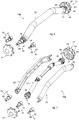
- Embodiments described using the attached drawings concern a multifunction device for prosthetic surgery indicated as a whole with reference number 10a and 10b in the attached drawings, according to the condition in which it is converted and used.
- the multifunction device is able to be converted to be used, in accordance with a milling configuration, as a milling device 10a for hip prosthetic surgery, in particular to make an acetabular seating, and, in accordance with a positioning configuration, as a positioning device 10b for positioning an acetabular cup 11 of a hip prosthesis in the acetabular seating as above.
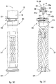
- the multifunction device comprises a single tubular oblong handling body 12 which develops along an operating axis A.
- the single handling body 12 is provided with a distal end 13 and with a proximal end 14 opposite each other.
- a distal attachment portion 15 and a proximal attachment portion 16 meaning, however, that they can be used indifferently for the functions that will be described in the following document, since they are interchangeable.
- the multifunction device also, comprises one or more acetabular milling cutters 17 able to be releasably connected to one of the attachment portions 15, 16 in the milling configuration as above.
- the multifunction device comprises a positioning element 20 able to be releasably fastened on one side directly to one of the attachment portions 15, 16 and on the other side to an acetabular cup 11 of a hip prosthesis, in said positioning configuration.
- the multifunction device comprises a transmission element 21 able to be releasably fastened to one of the attachment portions 16, 15 opposite the attachment portion 15, 16 to which the acetabular milling cutter 17 or the positioning element 20 is fastened, the transmission element 21 being configured so that, in the milling configuration as above or respectively in the positioning configuration as above, it can be used to transmit, by means of the transmission unit 27, a rotation from one of the attachment portions 16, 15 to the other of the attachment portions 15, 16, respectively associated with the specific acetabular milling cutter 17 or with the acetabular cup 11 associated with the positioning element 20.
- the positioning element 20, in the positioning configuration is able to be struck by a striker member to transmit an impact force, through the handling body 12 and the positioning element 20, to forcefully position the acetabular cup 11 associated with the positioning element 20.
- the handling body 12 has an elongated conformation in the direction of the operating axis A as above passing through the attachment portions 15, 16 and comprises a first shell 22 and a mating second shell 23 able to be stably coupled to each other in a releasable manner in order to house, inside, the transmission unit 27 as above.
- the transmission unit 27 allows the transmission of the rotary motion, generated by the drive member, from the proximal portion 16 to the distal portion 15 or vice versa.
- first shell 22 and the second shell 23 are identical and specular and are coupled to each other by means of tightening ring nuts 24 present on both the distal end 13 and also the proximal end 14, coaxially with the respective attachment portions 15, 16.
- the configuration described allows to simplify the assembly and disassembly of the handling body 12, both for the surgical operation and also to sterilize all its components.
- the handling body 12 has at least one inclined segment to aid the surgeon in moving and positioning the multifunction device toward the patient's acetabulum during the surgical operation.
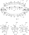
- the handling body 12 has two specular inclined segments 12a, 12c, in correspondence with the distal attachment portion 15 and the proximal attachment portion 16 angled with respect to said operating axis A, and a linear segment 12b, comprised between the inclined segments 12a, 12c, parallel to the operating axis A.
- the inclined segments 12a, 12c are angled with respect to the operating axis A by the same angle ⁇ comprised between about 15° and about 35°.
- the handling body 12 has a conformation symmetrical with respect to a central axis S orthogonal to the operating axis A and passing through the center of the handling body 12.
- the handling body 12 has a conformation symmetrical with respect to a coupling plane passing through the operating axis A and with respect to which the first shell 22 and the second shell 23 are coupled.
- This conformation of the handling body 12 is important both when the multifunction device is used as a milling device 10a to make an acetabular seating, and also when the device is used as a positioning device 10b to position and release the acetabular cup 11.
- the symmetrical conformation of the handling body 12 allows it to be used indiscriminately in one direction or another of the operating axis A as above.
- the transmission unit 27 comprises rotation shafts 28a, 28b, 28c, respectively corresponding to the segments 12a, 12b, 12c, and connected by cardan joints 29 which allow the transmission of the rotary motion with respect to the incident directions of the segments 12a, 12b, 12c.
- the rotation shafts 28a, 28c are the two outermost ones and are respectively connected on one side to the rotation shaft 28b and on the other, always by means of a cardan joint 29, to a connection interface 30 configured to be associated respectively with the proximal attachment portion 16 and with the distal attachment portion 15.
- the transmission unit 27 is operatively inserted inside the handling body 12, between the first shell 22 and the second shell 23.
- first shell 22 and the second shell 23 comprise a plurality of support cavities 25 and passage cavities 26 suitable to contain, once coupled, the transmission unit 27.
- the transmission unit 27 comprises bearings 31 which, during use, are positioned resting in the support cavities 25 and allow the rotation of the shafts 28a, 28b, 28c without any friction against the internal walls of the first shell 22 and the second shell 23.
- the bearings 31, as well as preventing friction of the rotation shafts 28a, 28b, 28c are configured to absorb the vibrations that are generated due to the inertia of the rotating members allowing a greater control of the milling device 10a by the surgeon.
- the attachment portions 15, 16 are, in particular, the same and interchangeable each comprising a base 32, a coupling head 35 and a plate 34 located intermediate.
- the base 32 is provided with a connection compartment 33 with a shape mating with that of the connection interface 30 for the operative connection to the transmission unit 27.
- both the base 32 and also the connection interface 30 are provided, on a lateral surface, respectively with connection holes 36a, 36b which during use are aligned in order to house an interference element which allows to make respectively the distal attachment portion 15 and the proximal attachment portion 16 integral at least temporarily with the transmission unit 27.
- the interference element can be chosen in a group comprising a pin, a screw, a rivet or other similar or comparable elements.
- connection holes 36a figs. 18-19
- a respective interference element 55 fig. 17
- the plate 34 and the coupling head 35 are configured to cooperate with one of the acetabular milling cutters 17 as above, with the positioning element 20, with a connection adapter possibly fastened to a respective acetabular milling cutter 17, with another connection adapter 19 fastened to a motorized drive member, or directly to the transmission element 21.
- the plate 34 is provided with a support surface 34a which, during use, is coordinated with and facing, on each occasion, striker surfaces 37, 39, 40 respectively of the acetabular milling cutter 17, of the connection adapters 19 and of the transmission element 21.
- the support surface 34a and the striker surfaces 37, 39, 40 can be coupled with more or less wide play, figs. 1-14 , or they can be located in contact, figs. 15-31 .
- the coupling head 35 develops from the plate 34 in the direction of the operating axis A, on the opposite side to that of the base 32.
- the coupling head 35 can have a prismatic shape.
- the prismatic shape of the coupling head 35 allows to improve the transmission of the rotary motion both on the drive member side, and also on the acetabular milling cutter 17 side.
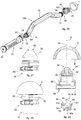
- the coupling head 35 can have a polygonal-shaped section, in particular, but not limited to, quadrangular ( figs. 1-14 ), or hexagonal ( figs. 15-31 ), to allow a selectively releasable connection with the acetabular milling cutter 17, with the positioning element 20, with one of the connection adapters possibly fastened to a respective acetabular milling cutter 17, with one of the other connection adapters 19 fastened to the motorized drive member, or directly with the transmission element 21.
- quadrangular figs. 1-14
- hexagonal figs. 15-31
- the hexagonal shape of the coupling head 35 allows, once the coupling with the acetabular milling cutter 17 has been made, to distribute the connection force in a more homogeneous manner between the coupling head 35 and an attachment part 45 of the acetabular milling cutter 17 as above. With the same transmitted force, the hexagonal shape, also, allows to reduce the sizes of the aperture 46 of the acetabular milling cutter 17 that houses the coupling head 35 as above.
- the coupling head 35 has clamping means 56 configured for a stable connection with the acetabular milling cutter 17, with the positioning element 20, with one of the connection adapters possibly fastened to a respective acetabular milling cutter 17, with one of the other connection adapters 19 fastened to the motorized drive member, or directly with the transmission element 21.
- the clamping means 56 comprise at least one presser device 42 (see for example figs. 4-5 , 8-9 , 13-14 ) configured to generate an interference with the translation in the direction of the operating axis A in order to ensure the clamping of the acetabular milling cutter 17, of the positioning element 20, of the connection adapters 19, or of the transmission element 21.
- the coupling head 35 has internally a housing compartment 41, open toward the outside, to house the presser device 42 as above.
- at least one portion of the presser device 42 has to exit the profile of the coupling head 35 in a direction orthogonal to the operating axis A.
- the housing compartment 41 is advantageously through so that possible organic residues, or possible condensation can easily be discharged during/after the washing and sterilization process.
- the presser device 42 can be chosen in a group comprising a spring presser, a ball presser, a spring and ball presser.
- the presser device 42 is of the spring and ball type and comprises an interference element 42a and an elastic element 42b that generates an elastic thrust on the interference element 42a in a direction orthogonal to the operating axis A.
- the clamping means 56 comprise at least one magnetic element 57 (see for example figs. 18, 20 , 23-24 , 29 , 31 ), for example a permanent magnet, such as an annular element, or ring, of magnetic material.
- the at least one magnetic element 57 is advantageously configured to selectively go on each occasion in abutment with striker surfaces 37, 39, 40 respectively of the acetabular milling cutter 17, of the connection adapters 19 and of the transmission element 21.
- the magnetic element 57 can be inserted in a specific seating made in the plate 34 and can define part of the support surface 34a.
- a milling device 10a which comprises the handling body 12, one or more acetabular milling cutters 17, and possibly one or more connection adapters able to be fastened on one side directly to the distal attachment portion 15 and on the other side to a respective one of said acetabular milling cutters 17.
- the acetabular milling cutter 17 can comprise a support part 43 that has a substantially hemispherical shape internally hollow and configured to support a plurality of cutting edges 44 distributed on it, in a desired manner.
- the acetabular milling cutter 17 can, also, comprise an attachment part 45 stably fixed to the base of the support part 43 and provided with the contact surface 37 and an aperture 46 configured to cooperate respectively with the plate 34 and with the coupling head 35 of the distal attachment portion 15 or of the proximal attachment portion 16.
- the shape of the aperture 46 is mating with the shape of the coupling head 35 so that no connection adapters are needed between them.
- the acetabular milling cutter 17 is configured to couple directly with the distal attachment portion 15 or with the proximal attachment portion 16 with respect to the operating axis A.
- the coupling head 35 once inserted into the aperture 46 in the direction of the operating axis A, will have penetrated therein by a height such that the presser device 42 is above the aperture 46 and below the support part 43 so as to axially clamp by interference the distal attachment portion 15 or the proximal attachment portion 16 with the acetabular milling cutter 17.
- the surface 37 of the attachment wall 45 can be resting on the support surface 34a of the plate 34 in order to increase the overall coupling surface and, therefore, improve the stability of the connection.
- the coupling head 35 once inserted into the aperture 46 in the direction of the operating axis A, will have penetrated therein by height such that the support surface 34a part of which has the magnetic element 57 goes into contact with the surface 37 of the attachment wall 45 suitably made of a metal material that has magnetic properties which allow an attraction suitable to make a stable connection.
- the milling device 10a also, comprises one or more further connection adapters 19 able to be fastened as a replacement of the transmission element 21, in the milling configuration, on one side directly to a respective attachment portion 16, 15 and on the other side to a motorized drive member.
- connection adapters 19 are shown each of which is configured to operatively connect a different motorized drive member, not shown, which will have a mating coupling compartment, with one of said distal attachment portions 15 or proximal attachment portion 16.
- connection adapter 19 comprises a universal attachment part 47, able to be fastened to the proximal attachment portion 16 or to the distal attachment portion 15, and a specialized attachment part 48, able to be fastened to the specific motorized drive member.
- the universal attachment part 47 is provided with a connection cavity 49 that has a shape mating with that of the coupling head 35.
- the universal attachment part 47 has at least one interference channel 50 passing from the connection cavity 49 toward the outside and suitable to at least partly house the presser device 42.
- the coupling head 35 is inserted in the connection cavity 49 so that the presser device 42 is partly inserted in the interference channel 50 as above.
- the universal attachment part 47 is provided with one or more interference channels 50 orthogonal to the operating axis A and angled with respect to each other so that the coupling head 35 is positioned so that the presser device 42 is aligned with any one of the angled directions of the interference channels 50.
- the interference channels 50 are through toward the outside so that possible organic residues, or possible condensation can easily be discharged during/after the washing and sterilization process.
- connection between the coupling head 35 and the connection adapter 19 occurs between the support surface 34a part of which has the magnetic element 57 and the striker surface 39. Also in this case, the particular hexagonal shape of the coupling head 35 allows a more effective transmission of the torque.
- the transmission element 21 is configured to be connected directly to the distal attachment portion 15 or to the proximal attachment portion 16 and is typically driven by the surgeon in the final step of the process of making the acetabular seating.
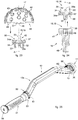
- Embodiments in which the multifunction device is converted into positioning device 10b are described using the figs. 10-14 and the figs. 25-31 and comprise the handling body 12 as above, the positioning element 20 able to be fastened on one side directly to the distal attachment portion 15 and on the other side to an acetabular cup 11 of a hip prosthesis.
- the positioning element 20 comprises a connection body 51 provided with a connection seating 53 for housing the distal attachment portion 15 or the proximal attachment portion 16, and a holding element 52 for the connection to the acetabular cup 11.
- connection body 51 advantageously has a flared shape in the direction of the holding element 52 so as not to interfere at other points with the acetabular cup 11.
- the positioning element 20 and the transmission element 21 are provided with respective releasable clamping devices 58, 59 which allow respectively to make the positioning element 20 integral with the handling body 12 and to clamp the rotation of the transmission element 21 which determines the motion of the transmission unit 27.
- the releasable clamping devices 58, 59 each comprise a respective tightening lever 60, 61 which allows to selectively make integral respectively the positioning element 20 and the transmission element 21 with the handling body 12.
- the tightening lever 60 of the releasable clamping device 58 of the positioning element 20 has an open position, suitable to allow the engagement of the positioning element 20 on an attachment portion 15, 16 and its correct angular position with respect to the operating axis A, and a closing position, suitable to make the positioning element 20 integral with the handling body 12.
- the closing position is necessary to guarantee that, during the impact action of the striker member on the transmission element 21 for the fixing in position of the acetabular cup 11 in the acetabular seating, made previously or already present, the strike inflicted transmits the force required for the fixing as above. In fact, otherwise, the strike inflicted by the striker member could be ineffective and transmit the impact force onto the surgeon's arm.
- the correct angular position with respect to the operating axis A is the one that guarantees the minimum bulk of the tightening lever 60 during the surgical technique and can be defined by aligning suitable references on the handling body 12 and on the positioning element 20.
- the opening position allows a rotation of the acetabular cup 11, previously fixed to the positioning element 20, to allow a correct alignment thereof for the insertion of fixing screws.
- the tightening lever 61 of the releasable clamping device 59 of the transmission element 21 has an open position, suitable to allow the engagement of the transmission element 21 on an attachment portion 15, 16 and its rotation with respect to the operating axis A in order to activate the transmission unit 27 and transmit the rotary motion from the distal end 13 to the proximal end 14, and a closing position, suitable to clamp the transmission element 21 to the handling body 12 preventing the activation of the transmission unit 27.
- the tightening levers 60, 61 are configured to at least partly wind the handling body 12 in correspondence with the distal end 13 and the proximal end 14 or vice versa.
- the tightening action of the tightening levers 60, 61 as above acts on the respective portion of the handling body 12 close to the ring nuts 24 on the opposite side with respect to the attachment portions 15, 16.
- the holding element 52 is fixed.
- the holding element 52 is mobile in rotation, about the operating axis A, in a housing cavity 62 of the positioning element 20.
- the housing cavity 62 is open on one side toward the connection seating 53, so as to allow the holding element 52 to connect with the attachment portion 15, 16 or with the attachment portion 16, 15, and on the opposite side toward the outside so as to allow the connection of the holding element 52 with the acetabular cup 11.
- the holding element 52 has a threaded tip for the anchoring to the acetabular cup 11.
- the screwing action allows to compact the holding element 52 and the acetabular cup 11 toward the attachment portion 15, 16 creating a very stable tightening.
- the transmission element 21 has the shape of a handle intended for the grip to rotate and position the acetabular cup 11 as described above and intended to be struck by a striker member to fix the acetabular cup 11 in its seating.
- the transmission element 21 comprises a coupling end 63 provided with the releasable clamping device 59 and an opposite abutment end 64 suitable to be struck by a striker member, for example by a surgical hammer.
- the coupling end 63 is, also, provided with a coupling seating to receive one of the attachment portions 15, 16.
- the acetabular cup 11 has a substantially hemispherical hollow shape and is provided, on its top, with a holding hole 54 in which the holding element 52 of the positioning element 20 is temporarily inserted, by interference ( fig. 10-14 ) or by screwing ( figs. 25-31 ).
- the transmission element 21 and the positioning element 20 are resting only on the corresponding ring nuts 24 of the handling body 12, in the direction of the operating axis A, so that the strike of the striker member on the transmission element 21 is transmitted through the handling body 12 onto the positioning element 20 without affecting the transmission unit 27.
- the acetabular cup 11 disengages from the holding element 52 of the positioning element 20 and remains in position in the acetabular seating made with the milling device 10a waiting to be permanently fixed therein by means of for example, screws or surgical cement.
- the positioning device 10b is, also, suitable to screw it into the acetabular seating made with the milling device 10a.
- At least the handling body 12 and the acetabular milling cutter 17 are made of biocompatible and hypoallergenic metal material.
- At least the handling body 12 and the acetabular milling cutter 17 are made of titanium which ensures high biocompatibility with the human body preventing problems of postoperative rejection; it is in fact biocompatible and hypoallergenic.
- connection adapters, the additional connection adapters 19, the transmission element 21, and the positioning element 20 can also be made of biocompatible and hypoallergenic metal material such as, for example, titanium.
- At least the handling body 12 and the acetabular milling cutter 17 are made of steel.
- Embodiments of the present invention concern a method to use the multifunction device for prosthetic surgery described above.
- the method to use the multifunction device provides the conversion from a milling configuration, to be used as a milling device 10a for prosthetic hip surgery, to a positioning configuration, to be used as a positioning device 10b to position an acetabular cup 11 of a hip prosthesis; the method as above comprises:
Landscapes
- Health & Medical Sciences (AREA)
- Life Sciences & Earth Sciences (AREA)
- Orthopedic Medicine & Surgery (AREA)
- Surgery (AREA)
- Oral & Maxillofacial Surgery (AREA)
- Engineering & Computer Science (AREA)
- Biomedical Technology (AREA)
- Heart & Thoracic Surgery (AREA)
- Animal Behavior & Ethology (AREA)
- General Health & Medical Sciences (AREA)
- Public Health (AREA)
- Veterinary Medicine (AREA)
- Transplantation (AREA)
- Medical Informatics (AREA)
- Molecular Biology (AREA)
- Dentistry (AREA)
- Nuclear Medicine, Radiotherapy & Molecular Imaging (AREA)
- Vascular Medicine (AREA)
- Physical Education & Sports Medicine (AREA)
- Cardiology (AREA)
- Surgical Instruments (AREA)
- Prostheses (AREA)
Applications Claiming Priority (2)
| Application Number | Priority Date | Filing Date | Title |
|---|---|---|---|
| IT102019000001801A IT201900001801A1 (it) | 2019-02-07 | 2019-02-07 | Dispositivo multifunzione per chirurgia protesica e relativo metodo di utilizzo |
| IT201900017084 | 2019-09-24 |
Publications (1)
| Publication Number | Publication Date |
|---|---|
| EP3692932A1 true EP3692932A1 (fr) | 2020-08-12 |
Family
ID=69374254
Family Applications (1)
| Application Number | Title | Priority Date | Filing Date |
|---|---|---|---|
| EP20155929.1A Withdrawn EP3692932A1 (fr) | 2019-02-07 | 2020-02-06 | Appareil multifonction |
Country Status (2)
| Country | Link |
|---|---|
| US (1) | US20200297356A1 (fr) |
| EP (1) | EP3692932A1 (fr) |
Families Citing this family (5)
| Publication number | Priority date | Publication date | Assignee | Title |
|---|---|---|---|---|
| WO2017029546A2 (fr) * | 2015-08-18 | 2017-02-23 | Incipio Devices Sa | Dispositif d'entraînement d'alésoir à décalage |
| BE1027082B1 (nl) * | 2019-02-27 | 2020-09-21 | Zimmer Inc | Hulpmiddel voor het ruimen van een handwortelbot |
| CN117883145B (zh) * | 2024-01-16 | 2025-01-14 | 北京和华瑞博医疗科技有限公司 | 髋臼锉连杆、末端执行器及手术机器人 |
| CN117898788B (zh) * | 2024-01-16 | 2025-02-18 | 北京和华瑞博医疗科技有限公司 | 弯髋臼锉连杆、末端执行器与手术机器人 |
| CN119700385A (zh) * | 2024-12-31 | 2025-03-28 | 保定向阳航空精密机械有限公司 | 一种快换式髋关节置换手术用工具 |
Citations (8)
| Publication number | Priority date | Publication date | Assignee | Title |
|---|---|---|---|---|
| US20030158559A1 (en) * | 2002-02-20 | 2003-08-21 | Diaz Robert L. | Minimally invasive total hip replacement |
| US20050038443A1 (en) * | 2002-12-12 | 2005-02-17 | Hedley Anthony K. | Surgical tools for joint replacement |
| US20060129158A1 (en) * | 2002-06-10 | 2006-06-15 | Penenberg Brad L | Apparatus for and method of providing a hip replacement |
| WO2008005941A2 (fr) * | 2006-06-30 | 2008-01-10 | Hodge Biomotion Technologies, Llc | système de façonnage de précision de l'acétabulum et implant acÉtabulaire de resurfaçage |
| US20080009874A1 (en) * | 2006-06-14 | 2008-01-10 | Biomet Manufacturing Corp. | Method and apparatus for reaming an acetabulum |
| US20090192515A1 (en) * | 2003-11-10 | 2009-07-30 | Andre Lechot | Inserter for minimally invasive joint surgery |
| US20160175112A1 (en) * | 2013-03-14 | 2016-06-23 | In'Tech Medical, Inc. | Modular acetabular cup impactor and reamer |
| US20180153699A1 (en) * | 2016-11-22 | 2018-06-07 | Storge Enterprises, LLC | Prosthetic Hip System |
-
2020
- 2020-02-06 EP EP20155929.1A patent/EP3692932A1/fr not_active Withdrawn
- 2020-02-07 US US16/785,432 patent/US20200297356A1/en not_active Abandoned
Patent Citations (8)
| Publication number | Priority date | Publication date | Assignee | Title |
|---|---|---|---|---|
| US20030158559A1 (en) * | 2002-02-20 | 2003-08-21 | Diaz Robert L. | Minimally invasive total hip replacement |
| US20060129158A1 (en) * | 2002-06-10 | 2006-06-15 | Penenberg Brad L | Apparatus for and method of providing a hip replacement |
| US20050038443A1 (en) * | 2002-12-12 | 2005-02-17 | Hedley Anthony K. | Surgical tools for joint replacement |
| US20090192515A1 (en) * | 2003-11-10 | 2009-07-30 | Andre Lechot | Inserter for minimally invasive joint surgery |
| US20080009874A1 (en) * | 2006-06-14 | 2008-01-10 | Biomet Manufacturing Corp. | Method and apparatus for reaming an acetabulum |
| WO2008005941A2 (fr) * | 2006-06-30 | 2008-01-10 | Hodge Biomotion Technologies, Llc | système de façonnage de précision de l'acétabulum et implant acÉtabulaire de resurfaçage |
| US20160175112A1 (en) * | 2013-03-14 | 2016-06-23 | In'Tech Medical, Inc. | Modular acetabular cup impactor and reamer |
| US20180153699A1 (en) * | 2016-11-22 | 2018-06-07 | Storge Enterprises, LLC | Prosthetic Hip System |
Also Published As
| Publication number | Publication date |
|---|---|
| US20200297356A1 (en) | 2020-09-24 |
Similar Documents
| Publication | Publication Date | Title |
|---|---|---|
| EP3692932A1 (fr) | Appareil multifonction | |
| EP2422754B1 (fr) | Impacteur décalé pour coupelle avec une plaque de saisie pour implants à mobilité double | |
| US7682363B2 (en) | Inserter for minimally invasive joint surgery | |
| US7335207B1 (en) | Minimally invasive cup impactor | |
| US8974537B2 (en) | Method for an articulating humeral head prosthesis | |
| US7857816B2 (en) | Inserter for minimally invasive joint surgery having interchangeable thread | |
| US7993348B2 (en) | Curved acetabular positioner, impactor and reamer handle | |
| CN100515353C (zh) | 改进的外科手术设备和使用方法 | |
| US7037310B2 (en) | Acetabular impactor | |
| JP6474739B2 (ja) | インプラントトライアル法 | |
| US20160135963A1 (en) | Method of attachment of implantable cup to a cup impactor | |
| KR20130090879A (ko) | 히프 내부 보철물용 히프 소켓 내로 소켓 삽입물을 삽입하기 위한 삽입 기구 | |
| AU2020260529B2 (en) | Ball and cup impactors for implanting a hip prosthesis | |
| JP7608462B2 (ja) | インプラント挿入ツールのための取り外し可能な傾斜ガイドおよび関連する外科的方法 | |
| JP2016509927A (ja) | インプラント試験 | |
| US20150127007A1 (en) | Instrument holder and grip for a medical, particularly a surgical, instrument | |
| US20190336145A1 (en) | Medical instrumentarium comprising sawing template | |
| EP3111897B1 (fr) | Impacteur orthopedique | |
| US20240156503A1 (en) | Surgical impacting tool couplings | |
| US20220330972A1 (en) | Milling device for surgery | |
| WO2022225472A1 (fr) | Système de prothèse d'épaule inversée | |
| JP6902612B2 (ja) | リサーフェシングプロテーゼの位置決めのための装置およびその装置の組立方法 | |
| US7172598B2 (en) | Force specific impacting device | |
| JP5324277B2 (ja) | 人工関節置換術用手術器具 | |
| IT201900001801A1 (it) | Dispositivo multifunzione per chirurgia protesica e relativo metodo di utilizzo |
Legal Events
| Date | Code | Title | Description |
|---|---|---|---|
| PUAI | Public reference made under article 153(3) epc to a published international application that has entered the european phase |
Free format text: ORIGINAL CODE: 0009012 |
|
| STAA | Information on the status of an ep patent application or granted ep patent |
Free format text: STATUS: THE APPLICATION HAS BEEN PUBLISHED |
|
| AK | Designated contracting states |
Kind code of ref document: A1 Designated state(s): AL AT BE BG CH CY CZ DE DK EE ES FI FR GB GR HR HU IE IS IT LI LT LU LV MC MK MT NL NO PL PT RO RS SE SI SK SM TR |
|
| AX | Request for extension of the european patent |
Extension state: BA ME |
|
| STAA | Information on the status of an ep patent application or granted ep patent |
Free format text: STATUS: THE APPLICATION IS DEEMED TO BE WITHDRAWN |
|
| 18D | Application deemed to be withdrawn |
Effective date: 20210213 |