EP3693120B1 - Verfahren zur herstellung einer punktschweissverbindung und stahlblech für punktschweissung - Google Patents
Verfahren zur herstellung einer punktschweissverbindung und stahlblech für punktschweissung Download PDFInfo
- Publication number
- EP3693120B1 EP3693120B1 EP18864200.3A EP18864200A EP3693120B1 EP 3693120 B1 EP3693120 B1 EP 3693120B1 EP 18864200 A EP18864200 A EP 18864200A EP 3693120 B1 EP3693120 B1 EP 3693120B1
- Authority
- EP
- European Patent Office
- Prior art keywords
- lines
- contact part
- steel sheet
- steel sheets
- spot welding
- Prior art date
- Legal status (The legal status is an assumption and is not a legal conclusion. Google has not performed a legal analysis and makes no representation as to the accuracy of the status listed.)
- Active
Links
Images


Classifications
-
- B—PERFORMING OPERATIONS; TRANSPORTING
- B23—MACHINE TOOLS; METAL-WORKING NOT OTHERWISE PROVIDED FOR
- B23K—SOLDERING OR UNSOLDERING; WELDING; CLADDING OR PLATING BY SOLDERING OR WELDING; CUTTING BY APPLYING HEAT LOCALLY, e.g. FLAME CUTTING; WORKING BY LASER BEAM
- B23K11/00—Resistance welding; Severing by resistance heating
- B23K11/10—Spot welding; Stitch welding
- B23K11/11—Spot welding
- B23K11/115—Spot welding by means of two electrodes placed opposite one another on both sides of the welded parts
-
- B—PERFORMING OPERATIONS; TRANSPORTING
- B23—MACHINE TOOLS; METAL-WORKING NOT OTHERWISE PROVIDED FOR
- B23K—SOLDERING OR UNSOLDERING; WELDING; CLADDING OR PLATING BY SOLDERING OR WELDING; CUTTING BY APPLYING HEAT LOCALLY, e.g. FLAME CUTTING; WORKING BY LASER BEAM
- B23K11/00—Resistance welding; Severing by resistance heating
- B23K11/10—Spot welding; Stitch welding
- B23K11/11—Spot welding
-
- B—PERFORMING OPERATIONS; TRANSPORTING
- B23—MACHINE TOOLS; METAL-WORKING NOT OTHERWISE PROVIDED FOR
- B23K—SOLDERING OR UNSOLDERING; WELDING; CLADDING OR PLATING BY SOLDERING OR WELDING; CUTTING BY APPLYING HEAT LOCALLY, e.g. FLAME CUTTING; WORKING BY LASER BEAM
- B23K11/00—Resistance welding; Severing by resistance heating
- B23K11/34—Preliminary treatment
-
- B—PERFORMING OPERATIONS; TRANSPORTING
- B23—MACHINE TOOLS; METAL-WORKING NOT OTHERWISE PROVIDED FOR
- B23K—SOLDERING OR UNSOLDERING; WELDING; CLADDING OR PLATING BY SOLDERING OR WELDING; CUTTING BY APPLYING HEAT LOCALLY, e.g. FLAME CUTTING; WORKING BY LASER BEAM
- B23K2101/00—Articles made by soldering, welding or cutting
- B23K2101/006—Vehicles
-
- B—PERFORMING OPERATIONS; TRANSPORTING
- B23—MACHINE TOOLS; METAL-WORKING NOT OTHERWISE PROVIDED FOR
- B23K—SOLDERING OR UNSOLDERING; WELDING; CLADDING OR PLATING BY SOLDERING OR WELDING; CUTTING BY APPLYING HEAT LOCALLY, e.g. FLAME CUTTING; WORKING BY LASER BEAM
- B23K2101/00—Articles made by soldering, welding or cutting
- B23K2101/18—Sheet panels
-
- B—PERFORMING OPERATIONS; TRANSPORTING
- B23—MACHINE TOOLS; METAL-WORKING NOT OTHERWISE PROVIDED FOR
- B23K—SOLDERING OR UNSOLDERING; WELDING; CLADDING OR PLATING BY SOLDERING OR WELDING; CUTTING BY APPLYING HEAT LOCALLY, e.g. FLAME CUTTING; WORKING BY LASER BEAM
- B23K2103/00—Materials to be soldered, welded or cut
- B23K2103/02—Iron or ferrous alloys
- B23K2103/04—Steel or steel alloys
Definitions
- the present invention relates to resistance spot welding of steel sheets.
- High strength steel sheets are large in amounts of carbon etc. of the base material so as to achieve strength. Further, in spot welding, the weld zone is heated, then immediately quenched, so the spot weld zone of high strength steel sheets becomes martensite structures and the hardness rises and toughness falls at the weld zone and heat affected zone. Further, at the weld zone, the welded joint becomes large in tensile residual stress due to the locally occurring expansion and contraction accompanying transformation.
- spot welding of high strength steel sheets as a method for improving the toughness of the spot weld zone and securing the joint strength, there is the method of two-stage applying current comprising main current for forming a nugget then further post heat current for tempering the spot weld zone.
- post heat current can be used to anneal the spot weld zone (nugget part and heat affected zone) to lower the hardness of the weld zone.
- delayed fracture hydrogen embrittlement cracking
- Delayed fracture is mainly governed by the three factors of the hardness of the steel sheets, the residual stress, and the amount of hydrogen in the steel sheets, but the spot weld zone is high in hardness and large in tensile residual stress, so if hydrogen penetration occurs, there is a possibility of delayed fracture being caused.
- PTL 1 discloses a spot welding technique raising the electrode force at the time of the post heat current after the time of the main current for forming the nugget compared with the electrode force P1 at the time of the main current and squeezing by the high electrode force P2 so as to introduce compressive residual stress to the surroundings of the weld zone and improve the hydrogen embrittlement resistance.
- the art disclosed in PTL 1 can reduce the tensile residual stress of a weld zone, so is art effective for suppressing delayed fracture, but the effect of hydrogen penetrating the weld zone etc. at the time of welding is not particularly considered. It is desirable to suppress hydrogen embrittlement cracking due to penetration of hydrogen so as to further improve the hydrogen embrittlement resistance.
- An object of the present invention considering such a situation, is to provide spot welding art able to suppress penetration of hydrogen, one of the factors behind delayed fracture, at the time of spot welding.
- steel sheets before spot welding are stored in a state coated with oil (rust-preventing oil, cleaning oil, working oil, etc.).
- oil rust-preventing oil, cleaning oil, working oil, etc.
- the oil is removed by volatization by the heat of the spot welding, so usually spot welding is performed without removing the oil deposited on the steel sheets.
- Oil contains moisture or hydrogen, so the inventors thought that possibly the oil was a factor behind penetration of hydrogen at the steel sheets and therefore investigated the effects of hydrogen in the case of spot welding steel sheets with oil as deposited.
- the plurality of lines formed in advance form channels for discharging the oil and the oil is discharged to outside of the weld zone without being held between the steel sheets, so it becomes difficult for hydrogen to penetrate the weld zone.
- a location where the steel sheets contact each other to form a contact part at the time of initial squeezing of the spot welding is worked in advance to form a plurality of lines (line-shaped grooves) running through the contact part and connected to the outside of the contact part.
- spot welding is performed whereby even if the facing surfaces of steel sheets are coated with oil, the oil which had been coated there at the time of initial squeezing can be discharged from the contact part to the outside and oil can be kept from being trapped in the contact part and hydrogen kept from penetrating into the weld zone.
- the lines may be straight or curved.
- the "steel sheet" used in manufacture of the welded joint includes cut sheets cut into sizes suitable for press-forming and tailored blanks comprised of a plurality of different types of steel sheets butt welded together. Further, blanks shaped for press-forming the steel sheets and press-formed members are also included.
- the steel sheet members are supplied to the spot welding processing with oil as coated. Therefore, first, the inventors investigated if the oil became a source of penetration of hydrogen.
- test pieces three types of test pieces of sizes of 30 mm ⁇ 30 mm such as shown next were prepared.
- oil rust-preventing oil (manufactured by Nihon Parkerizing Co., Ltd. NOX-RUST530F(60)) was used:
- test pieces A1 and A2 were spot welded under the common welding conditions of the following Table 1 with constant electrode forces and changed weld currents to form nuggets of 3 mm, 4 mm, and 5 mm size, then were immediately cooled by liquid nitrogen. After that, the welded test pieces were cut into sizes of 10 mm ⁇ 10 mm so as to include the nuggets.
- the amounts of hydrogen entering the spot weld zone in the welded test pieces A1 and A2 were measured by raising the temperatures of the test pieces to make them discharge the hydrogen and measuring the discharged amounts of hydrogen by a gas chromatography.
- test pieces B were squeezed and applied with current in the same way as spot welding to form nuggets of similar sizes. The amounts of hydrogen of the test pieces B after applying current were measured in the same way.
- the results for the test pieces A1 and A2 are shown in FIG. 1 .
- “a” shows the results for the test pieces A1
- “b” shows the results for the test pieces A2.
- the inventors studied means for discharging oil from the inside to the outside of the steel sheet contact part at the time the steel sheets contact each other at the start of squeezing. As a result, they came up with the idea of forming in advance passages enabling discharge of oil to outside of the contact part so as to run through the contact part and connected to the outside of the contact part and conducted the following test.
- the inventors polished the entire surfaces of steel sheets of a size of 30 ⁇ 30 mm and thickness of 1 mm using abrasive papers with a #80 and #400 grain size so as to prepare steel sheets formed with large numbers of lines (fine line-shaped grooves) on the surfaces. For comparison, they also prepared unpolished steel sheets.
- the inventors prepared pluralities of steel sheets comprised of unpolished steel sheets overlaid with oil interposed at the facing surfaces and steel sheets comprised of polished steel sheets overlaid with polished surfaces being overlaid and with oil interposed between the facing surfaces. They spot welded the center parts of the overlaid steel sheets under the conditions of Table 3.
- the range of formation of the lines is made the range at which the steel sheets contact at the facing surfaces of the steel sheets at the start of squeezing by the electrodes in the spot welding (referred to as "initial contact part”. Note that sometimes abbreviated as “contact part”) and a range beyond that. If the lines are not formed beyond the range at which the steel sheets contact each other, the oil cannot be discharged from the contact part to the outside.
- the range of the initial contact part can be evaluated by pressure measurement film.
- the lines may be formed for each spot welding location of the steel sheet or may be formed to include a plurality of spot welding locations.
- the lines have to continue from at least the inside of the contact part to the outside of the contact part.
- the two end parts of the lines are preferably positioned outside of the contact part, that is, run from the outside of the contact part through the contact part to the outside of the contact part.
- FIG. 3 Representative forms of the lines are shown in FIG. 3 .
- "a” shows the case of forming non-intersecting lines
- "b” shows the case of forming intersecting lines
- "c” shows the case of densely forming lines by abrasive paper
- "d” shows the case of forming curved lines.
- the number of lines is preferably four or more in total for the facing surfaces. If there are not four or more lines, the amount of oil removed from the overall range of the initial contact part tends to be small.
- the area of the biggest range among the ranges divided by the lines and/or outer circumference of the contact surface is preferably 30% or less of the area of the contact part. If over 30%, the oil removed tends to be small.
- the width of the lines and the surface roughness Sa showing the roughness of the surface of the contact part lines differ when forming lines on one or on both of the facing surfaces of the steel sheets. They are made the following conditions (a), (b).
- the surface roughness Sa relates to the depth of the lines (depth of grooves). If satisfying the conditions prescribed below in accordance with the number of lines, it is possible to sufficiently remove the oil, so this is preferable. Note that when the number of lines is large, a preferable effect is obtained by just satisfying Sa.
- the other steel sheet need not be provided with lines or may be provided with three or less lines.
- Sa is a surface roughness parameter defined by ISO25178.
- the divided ranges, widths of the lines (grooves), and Sa can be measured by a laser microscope.
- Sa is used as a metric for surface roughness, but in the present invention, it is necessary that lines acting as channels for oil be formed on the surface of the steel sheet. It is not enough that the surface be rough in state. Therefore, the widths and numbers of the lines are prescribed together as above.
- the method of formation of the lines at the spot welding zone of the steel sheets aside from the method used in the above experiment of polishing the surface by abrasive paper or abrasive cloth, the method of stamping by a die to insert lines, the method of scratching out lines by a scriber, and other suitable methods can be employed.
- the location becoming the contact part at the time of initial squeezing in the spot welding is formed with an unevenness of stripe pattern.
- this is characterized by providing the die with fine projections and giving an unevenness of stripe pattern to the material worked in the press forming operation, that is, the steel sheet or steel pipe, at the sliding position.
- the arrangement of the projections or the shape of the pattern imparted is not particularly limited.
- the method of imparting stripe shapes to the die is not particularly limited, but for example it is possible to impart them by an end mill. For example, consider the drawing work such as shown in FIG. 4 .
- a punch 32 can be used to apply pressure to a steel sheet 31 gripped by a blank holder 33 and die 34 to work the steel sheet 31 into a recessed shape.
- the part of the steel sheet 31 held between the blank holder 33 and the die 34 receives contact pressure in the sheet thickness direction by the blank holder 33 and the die 34 and slides when the steel sheet 31 deforms.
- a pattern is formed at the surface of the sliding steel sheet 31.
- the size and array of the projections provided at the die may be suitably determined in accordance with the pattern to be formed.
- the surface sliding against the steel sheet or steel pipe may be formed with a pattern of projections of a height of 10 to 100 ⁇ m and intervals of 50 to 1000 ⁇ m.
- the surface of the die 34 was formed with the regular pattern shown in FIG. 5 and the steel sheet was drawn by a pressing load of 2.9 MPa and 4.8 MPa under control of the cushion pressure.
- FIG. 6 shows the states of the surfaces after drawing.
- Table 5 shows the Sa (arithmetic average height: ⁇ m) and Str at the time of no polishing, #80 polishing and #400 polishing and drawing by pressing loads of 2.9 MPa and 4.8 MPa.
- Table 5 the average amounts of hydrogen of the weld metal part when spot welding with the respective surface conditions facing each other are shown.
- the reference results of no polishing are the same as in Table 4. From the results, it will be understood that if the Str is 0.3 or less, there is the effect that the average amount of hydrogen can be remarkably decreased (80% or more) and the possibility of hydrogen embrittlement cracking can be greatly reduced. Further, it will be understood that even with polishing, if the Str is small, the amount of hydrogen entering the spot weld zone can be greatly decreased.
- the pattern of lines has to at least run from the inside of the contact part to the outside of the contact part.
- the two end parts of the lines are positioned outside of the contact part, that is, the lines run from the outside of the contact part through the contact part to the outside of the contact part.
- the unevenness of stripe pattern is preferably a regular pattern giving an aspect ratio (Str) of the surface conditions of 0.3 or less in order to sufficiently remove rust-preventing oil.
- Str is a parameter defined by ISO25178-2 expressing the isotropy and anisotropy of the surface conditions. If close to 0, it indicates there are lines etc., while if close to 1, it indicates the surface is not directionally dependent. Providing four or more stripes is preferable in removing rust-preventing oil from the entire range of the initial contact part.
- a first steel sheet member comprised of a steel sheet worked using a die and a steel sheet or a second steel sheet member comprised of a worked steel sheet are overlaid and spot welded. If the first steel sheet member is formed with an unevenness of stripe pattern, the steel sheet or second steel sheet member to be spot welded with may be formed with a pattern or may not. Further, the number of the overlaid steel sheets is not limited to two. It may be three or more as well. Further, the types, compositions of constituents, and thicknesses of the overlaid steel sheets may all be the same or may be different from each other.
- the invention is not limited to a joint comprised of separate steel sheets.
- the "steel sheet" to be spot welded with the first steel sheet member may also be part of the first steel sheet member.
- the punch 62 and/or pad 63 may be provided with projecting parts and made to slide so as to impart an unevenness of stripe pattern.
- the pad can also be controlled to a fixed distance by using a distance block (not shown) in the same way as the case of the blank holder.
- the upper die 72 and/or the lower die 73 may be provided with projecting parts so as to form an unevenness of stripe pattern at the location of the steel sheet 71 at the sliding location of the steel sheet gripped by the upper die 72 and lower die 73.
- a distance block (not shown) to impart any depth of stripe grooves.
- the present invention can also be applied to the case where the steel sheet member is a steel pipe.
- the steel sheet member is a steel pipe.
- by giving projections to the pressure die it is possible to give an unevenness of stripe pattern to the surface of the steel pipe sliding with the pressure die.
- the steel pipe is held between a bending die 82 and a clamping die 83 provided at the outer circumferential surface of the steel pipe 81.
- the pressure die 84 is used to press the steel pipe in the bending die direction while the bending die and clamping die are rotated.
- the steel pipe is stretched while being made to bend.
- the steel pipe 81 slides with respect to the pressure die 84, so by giving projections to the surface of the pressure die 84 contacting the steel pipe 81, it is possible to give an unevenness of stripe pattern to the surface of the steel pipe.
- the die position can be controlled to a fixed distance, so it is possible to give an unevenness of stripe pattern of any groove depth. Further, the pressure by a usual pressure die is 1 to 10 MPa or so, therefore is suitable for the present invention.
- the present invention can be applied.
- the punch 92 with projecting parts, it is possible to give an unevenness of stripe pattern to the sliding position of the steel pipe 91.
- the steel sheets used in the present invention include cut sheets cut to sizes suitable for press forming (for example, 1 m ⁇ 1 m) and tailored blanks comprised of pluralities of different types of steel sheets butt welded together.
- the steel sheets used in the present invention need only be sheet like at the parts to be overlaid. They do not have to be sheets as a whole. For example, flange parts of members pressed formed into specific shapes of cross-sectional hat shapes etc. are also included.
- the number of the overlaid steel sheets is not limited to two. It may be three or more as well. Further, the types, compositions of constituents, and thicknesses of the overlaid steel sheets may all be the same or may be different from each other.
- the overlaid steel sheets may also be comprised of a plurality of steel sheets butt welded together. Further, the invention is not limited to a joint formed from separate steel sheets. A single steel sheet may be shaped into a tube or other predetermined shape and the end parts overlaid.
- the strength of the steel sheet is not particularly limited. However, the problem of delayed fracture easily occurs in the case of spot welding high strength steel sheet, so the present invention is particularly effective for steel sheet with a tensile strength of 500 MPa or more and further steel sheet with a tensile strength of 780 MPa or more.
- timing of formation of the lines is not particularly limited. As one example, it is possible to form the lines right before spot welding the steel sheets.
- the lines may be formed at the locations scheduled for spot welding at the stage of the steel sheets (including cut sheets and tailored blanks) or the stage of shaping the blanks.
- the inventors ran tests spot welding two overlaid test pieces comprised of strength 980 MPa class steel sheets of sizes of 30 ⁇ 30 mm and thicknesses of 1 mm. At that time, on one surface (single surface) or two surfaces (both surfaces) of sides of overlaid test pieces forming the facing surfaces, they used either dies (stamping), scribers, or abrasive paper to form a plurality of lines for enabling oil to escape and in constant widths near the parts scheduled for welding. For the oil, rust-preventing oil (made by Nihon Parkerizing Co., Ltd., NOX-RUST530F(60)) was used.
- the conditions were set so that the initial contact part at the time of spot welding become a circular shape of a diameter of 3 mm.
- the lines were formed to pass through the contact part and extend by 1 mm or more to the outside from the outer circumference of the initial contact part. However, in some of the test pieces, for comparison, the lines were formed so as not to depart from the outer circumference of the initial contact part.
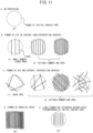
- the patterns of the lines formed are shown in FIG. 11 .
- the patterns of lines include a pattern with no processing indicated by a1, patterns of lines formed by dies (stamping) or scribers and not intersecting (b1, b2), patterns of similar lines intersecting (c1, c2), and a pattern of a large number of lines formed by abrasive paper (d1). Further, a pattern with lines formed so as not to leave the outer circumference of the initial contact part was made the pattern (e1).
- b1 and c1 are examples of small numbers of lines (large areas of ranges divided by lines or outer circumference)
- b2 and c2 are examples of suitable numbers of lines (suitable areas of ranges divided by lines or outer circumference).
- test pieces formed with the lines were counted for numbers of lines and measured for surface roughness Sa. Further, when the number of lines N was less than 20, the area of the maximum range in the ranges divided by the lines or outer circumference of the contact surface was measured.
- the test piece was spot welded, it was immediately cooled by liquid nitrogen. After that, the welded test piece was cut into a 10 mm ⁇ 10 mm size so as to include the nugget.
- the amount of hydrogen entering the spot weld zone was measured by raising the temperature of the test piece to make it discharge the hydrogen and measuring the discharged amount of hydrogen by a gas chromatography. The rate of temperature rise was 100°C/hour, the peak temperature was 200°C, and the amount of hydrogen discharged up to 200°C was made the amount of hydrogen entering the spot weld zone.
- Table 6 uses as the value of Sa required for decreasing hydrogen (lower limit value) the values ( ⁇ m) calculated from formula (-0.09 ⁇ N+2) in the case of both surfaces and from formula (-0.07 ⁇ N+1.9) in the case of single surfaces when N ⁇ 20 and 0.2 ⁇ m in the case of single surfaces and 0.5 ⁇ m in the case of both surfaces when N ⁇ 20.
Landscapes
- Engineering & Computer Science (AREA)
- Mechanical Engineering (AREA)
- Resistance Welding (AREA)
Claims (15)
- Verfahren zur Herstellung einer Punktschweißverbindung überlappender Stahlbleche (3, 4), dadurch gekennzeichnet, dassan einer oder beiden Oberflächen der Stahlbleche (3, 4), die die Gegenflächen (5) der Stahlbleche (3, 4) werden, eine Stelle, an der die Stahlbleche (3, 4) einander kontaktieren, um ein Kontaktteil beim anfänglichen Pressen der Punktschweißung zu bilden, vorab so bearbeitet wird, dass Linien mehrerer linienförmiger Nuten gebildet werden, die das Kontaktteil durchlaufen und mit der Außenseite des Kontaktteils verbunden sind, unddas Punktschweißen an der Stelle des Kontaktteils durchgeführt wird.
- Verfahren zur Herstellung einer Punktschweißverbindung nach Anspruch 1, wobei die Anzahl der Linien jeweils mindestens vier an beiden Oberflächen der Stahlbleche (3, 4) beträgt, die die Gegenflächen (5) der Stahlbleche (3, 4) werden, und hinsichtlich der Breiten der Linien und der Oberflächenrauheit Sa der Stahlblechoberflächen des Kontaktteils,die Oberflächen der Stahlbleche (3, 4), die die Gegenflächen (5) werden, bearbeitet werden, um mehrere Linien zu bilden, so dassbei einer Linienanzahl N von 4≤N<20 die Breite der Linien mindestens 0,2/N (mm) beträgt und die Oberflächenrauheit Sa mindestens -0,09 × N+2 (µm) beträgt und bei einer Linienanzahl N von 20≤N die Oberflächenrauheit Sa mindestens 0,2 µm beträgt.
- Verfahren zur Herstellung einer Punktschweißverbindung nach Anspruch 2, wobei eine Fläche des größten Bereichs unter den Bereichen, die durch die Linien oder den Außenumfang des Kontaktteils unterteilt werden, höchstens 30 % der Fläche des Kontaktteils beträgt.
- Verfahren zur Herstellung einer Punktschweißverbindung nach Anspruch 1, wobei die Anzahl der Linien jeweils mindestens vier an mindestens einer der Oberflächen der Stahlbleche (3, 4) beträgt, die die Gegenflächen (5) der Stahlbleche (3, 4) werden, undhinsichtlich der Breiten der Linien und der Oberflächenrauheit Sa der Stahlblechoberflächen des Kontaktteils,die Oberfläche des mindestens einen Stahlblechs, die die Gegenfläche wird, bearbeitet wird, um mehrere Linien zu bilden, so dassbei einer Linienanzahl N von 4≤N<20 die Breite der Linien mindestens 0,4/N (mm) beträgt und die Oberflächenrauheit Sa mindestens -0,07 × N+1,9 (µm) beträgt und bei einer Linienanzahl N von 20≤N die Oberflächenrauheit Sa mindestens 0,5 µm beträgt.
- Verfahren zur Herstellung einer Punktschweißverbindung nach Anspruch 4, wobei eine Fläche des größten Bereichs unter den Bereichen, die durch die Linien oder den Außenumfang des Kontaktteils unterteilt werden, höchstens 30 % der Fläche des Kontaktteils beträgt.
- Stahlblech zur Verwendung beim Punktschweißen,wobei eine Stelle des Stahlblechs, die ein Kontaktteil wird, das ein anderes Stahlblech beim anfänglichen Pressen der Punktschweißung kontaktiert, vorab mit Linien mehrerer linienförmiger Nuten ausgebildet ist, die eine streifenmusterförmige Unebenheit bilden, die das Kontaktteil durchläuft und mit der Außenseite des Kontaktteils verbunden ist,wobei die nachstehenden Kennwerte (a1) oder (a2) erfüllt sind:(a1) die Linienanzahl N beträgt 4≤N<20, die Breite der Linien beträgt mindestens 0,2/N (mm), die Oberflächenrauheit Sa beträgt mindestens -0,09 × N+2 (µm),(a2) die Linienanzahl N beträgt 20≤N, die Oberflächenrauheit Sa beträgt mindestens 0,2 µm.
- Stahlblech zur Verwendung beim Punktschweißen nach Anspruch 6, wobei die streifenmusterförmige Unebenheit ein regelmäßiges Muster ist, das ein Aspektverhältnis des Oberflächenzustands Str, definiert durch ISO25178-2, die die Isotropie und Anisotropie der Oberflächenzustände ausdrückt, von höchstens 0,3 ergibt.
- Stahlblech zur Verwendung beim Punktschweißen nach Anspruch 7, wobei die nachstehenden Kennwerte (a3) oder (a4) erfüllt sind:(a3) im Inneren des Kreises beträgt die Linienanzahl N 4≤N<20, die Breite der Linien beträgt mindestens 0,4/N (mm) und die Oberflächenrauheit Sa beträgt mindestens -0,07 × N+1,9 (µm),(a4) im Inneren des Kreises beträgt die Linienanzahl N 20≤N, die Oberflächenrauheit Sa des Stahlblechs beträgt mindestens 0,5 µm.
- Stahlblech zur Verwendung beim Punktschweißen nach Anspruch 7, wobei eine Fläche des größten Bereichs unter den Bereichen, die durch die Linien oder den Außenumfang des Kreises unterteilt werden, höchstens 30 % der Fläche des Kreises beträgt.
- Stahlblech zur Verwendung beim Punktschweißen nach Anspruch 7, wobei die Länge der Linien mindestens 5 mm beträgt.
- Stahlblech zur Verwendung beim Punktschweißen nach Anspruch 7, wobei die Linien Geraden sind.
- Verfahren zur Herstellung einer Punktschweißverbindung nach Anspruch 1, wobei ein Aspektverhältnis der Oberflächenzustände Str, definiert durch ISO 25178-2, des Kontaktteils, das mit Linien mehrerer linienförmiger Nuten ausgebildet ist, höchstens 0,3 beträgt.
- Verfahren zur Herstellung einer Punktschweißverbindung nach Anspruch 1, wobei die Linien mehrerer linienförmiger Nuten gebildet werden, indem ein Werkzeug mit vorstehenden Teilen zumindest an einem Teil der das Stahlblech kontaktierenden Oberfläche verwendet und das Stahlblech veranlasst wird, im Hinblick auf das Werkzeug zu gleiten, um dadurch vorab eine streifenmusterförmige Unebenheit zu bilden, die das Kontaktteil durchläuft und mit der Außenseite des Kontaktteils verbunden ist.
- Verfahren zur Herstellung einer Punktschweißverbindung nach Anspruch 13, wobei ein Aspektverhältnis der Oberflächenzustände Str, definiert durch ISO 25178-2, die die Isotropie und Anisotropie der Oberflächenzustände ausdrückt, des mit der streifenmusterförmigen Unebenheit ausgebildeten Kontaktteils höchstens 0,3 beträgt.
- Stahlblechbauteil zur Verwendung beim Punktschweißen,wobei eine Stelle des Stahlblechbauteils, die ein Kontaktteil wird, das ein Stahlblech oder ein zweites Stahlblechbauteil kontaktiert, zu dem ein Stahlblech beim anfänglichen Pressen der Punktschweißung bearbeitet wird, vorab mit Linien mehrerer linienförmiger Nuten ausgebildet ist, die eine streifenmusterförmige Unebenheit bilden, die das Kontaktteils durchläuft und mit der Außenseite des Kontaktteils verbunden ist,wobei die nachstehenden Kennwerte (a1) oder (a2) erfüllt sind:(a1) die Linienanzahl N beträgt 4≤N<20, die Breite der Linien beträgt mindestens 0,2/N (mm), die Oberflächenrauheit Sa beträgt mindestens -0,09 × N+2 (µm),(a2) die Linienanzahl N beträgt 20≤N, die Oberflächenrauheit Sa beträgt mindestens 0,2 µm.
Applications Claiming Priority (2)
| Application Number | Priority Date | Filing Date | Title |
|---|---|---|---|
| JP2017195134 | 2017-10-05 | ||
| PCT/JP2018/037476 WO2019070075A1 (ja) | 2017-10-05 | 2018-10-05 | スポット溶接継手の製造方法、並びにスポット溶接用鋼板、及びスポット溶接用鋼板部材 |
Publications (3)
| Publication Number | Publication Date |
|---|---|
| EP3693120A1 EP3693120A1 (de) | 2020-08-12 |
| EP3693120A4 EP3693120A4 (de) | 2021-08-18 |
| EP3693120B1 true EP3693120B1 (de) | 2024-12-04 |
Family
ID=65995174
Family Applications (1)
| Application Number | Title | Priority Date | Filing Date |
|---|---|---|---|
| EP18864200.3A Active EP3693120B1 (de) | 2017-10-05 | 2018-10-05 | Verfahren zur herstellung einer punktschweissverbindung und stahlblech für punktschweissung |
Country Status (9)
| Country | Link |
|---|---|
| US (1) | US11628511B2 (de) |
| EP (1) | EP3693120B1 (de) |
| JP (1) | JP6927317B2 (de) |
| KR (1) | KR102319901B1 (de) |
| CN (1) | CN111107956B (de) |
| BR (1) | BR112020005457A2 (de) |
| CA (1) | CA3078445A1 (de) |
| MX (1) | MX2020003898A (de) |
| WO (1) | WO2019070075A1 (de) |
Family Cites Families (11)
| Publication number | Priority date | Publication date | Assignee | Title |
|---|---|---|---|---|
| US4633054A (en) * | 1984-02-24 | 1986-12-30 | Aluminum Company Of America | Resistance welding method |
| JPS645832A (en) * | 1987-06-30 | 1989-01-10 | Aichi Steel Works Ltd | Composite metal plate excellent in vibration-damping property and heat resistance |
| JPH06304765A (ja) * | 1993-04-20 | 1994-11-01 | Sky Alum Co Ltd | 抵抗スポット溶接用アルミニウム合金板および抵抗スポット溶接方法 |
| JP3797853B2 (ja) * | 2000-07-28 | 2006-07-19 | 独立行政法人科学技術振興機構 | 通電接合によるアルミニウム合金複合部材の製造方法 |
| US7268319B2 (en) * | 2004-05-04 | 2007-09-11 | General Motors Corporation | Method of metallurgically bonding articles and article therefor |
| KR100838263B1 (ko) * | 2007-04-13 | 2008-06-17 | 정정운 | 박판 내식성 클래드 판재 제조방법 |
| JP6105993B2 (ja) * | 2013-03-25 | 2017-03-29 | 日新製鋼株式会社 | 抵抗熱により接合されたステンレス鋼箔製成型品 |
| JP6194765B2 (ja) * | 2013-11-08 | 2017-09-13 | 新日鐵住金株式会社 | 高強度鋼板のスポット溶接方法 |
| EP3199657B1 (de) | 2014-09-25 | 2019-02-13 | JFE Steel Corporation | Stahlband für widerstandsgeschweisstes stahlrohr, widerstandsgeschweisstes stahlrohr und verfahren zur herstellung des stahlbandes für widerstandsgeschweisstes stahlrohr |
| KR20160053316A (ko) | 2014-11-03 | 2016-05-13 | 주식회사 새한산업 | 자동차용 구조물과 그 제조 방법 |
| US10018329B1 (en) * | 2017-07-06 | 2018-07-10 | Richard S Belliveau | Framing contrast of multiparameter theatrical lighting fixtures |
-
2018
- 2018-10-05 MX MX2020003898A patent/MX2020003898A/es unknown
- 2018-10-05 KR KR1020207008893A patent/KR102319901B1/ko active Active
- 2018-10-05 BR BR112020005457-7A patent/BR112020005457A2/pt not_active IP Right Cessation
- 2018-10-05 CA CA3078445A patent/CA3078445A1/en not_active Abandoned
- 2018-10-05 JP JP2019547040A patent/JP6927317B2/ja active Active
- 2018-10-05 EP EP18864200.3A patent/EP3693120B1/de active Active
- 2018-10-05 WO PCT/JP2018/037476 patent/WO2019070075A1/ja not_active Ceased
- 2018-10-05 US US16/652,351 patent/US11628511B2/en active Active
- 2018-10-05 CN CN201880060729.4A patent/CN111107956B/zh active Active
Also Published As
| Publication number | Publication date |
|---|---|
| KR20200047617A (ko) | 2020-05-07 |
| BR112020005457A2 (pt) | 2020-09-24 |
| JP6927317B2 (ja) | 2021-08-25 |
| US11628511B2 (en) | 2023-04-18 |
| CN111107956A (zh) | 2020-05-05 |
| MX2020003898A (es) | 2020-08-20 |
| CA3078445A1 (en) | 2019-04-11 |
| KR102319901B1 (ko) | 2021-11-01 |
| US20200269341A1 (en) | 2020-08-27 |
| EP3693120A1 (de) | 2020-08-12 |
| CN111107956B (zh) | 2022-01-04 |
| JPWO2019070075A1 (ja) | 2020-10-22 |
| WO2019070075A1 (ja) | 2019-04-11 |
| EP3693120A4 (de) | 2021-08-18 |
Similar Documents
| Publication | Publication Date | Title |
|---|---|---|
| US20200156177A1 (en) | Overlap-welded member, automobile part, method of welding overlapped portion, and method of manufacturing overlap-welded member | |
| JP6107939B2 (ja) | スポット溶接方法 | |
| JP4934283B2 (ja) | 車体補強用部材 | |
| CN107530754B (zh) | 压制加工装置、压制加工方法 | |
| US12553096B2 (en) | Blank and structural member | |
| EP3839079A1 (de) | Heissgeprägtes teil und verfahren zur herstellung davon | |
| EP2351623B1 (de) | Verfahren zur herstellung eines verformten querschnitts und formartikel mit vierseitigem querschnitt mit hervorragender punktschweissfähigkeit | |
| EP2055405B1 (de) | Verfahren zum pressformen von blechen | |
| EP3165297B1 (de) | Biegeverfahren | |
| EP2883627B1 (de) | Verfahren zur herstellung eines stahlrohrs | |
| JP7059572B2 (ja) | 溶接継手の製造方法及び溶接継手 | |
| EP3693120B1 (de) | Verfahren zur herstellung einer punktschweissverbindung und stahlblech für punktschweissung | |
| KR20230165915A (ko) | 프레스 성형 방법 | |
| JP2008093703A (ja) | 溶接部特性の良好な電縫管の製造装置 | |
| US20250144693A1 (en) | Steel material, auto part, shearing apparatus and method of production of steel material | |
| JP7332879B2 (ja) | チタン板のプレス用金型及びチタン板のプレス成形方法 | |
| JP2005138112A (ja) | プレス加工方法 | |
| KR102859624B1 (ko) | 기계적 체결을 위한 저항 점용접 연화 열처리 방법 | |
| EP4335563B1 (de) | Skelettelement | |
| JP4277724B2 (ja) | 疲労特性に優れた2次加工鋼管 | |
| EP4501516A1 (de) | Verfahren zur herstellung einer projektionsschweissnaht, projektionsschweissnaht und automobilkomponente | |
| JP2002059220A (ja) | ハイドロフォーム加工性に優れた電縫鋼管 | |
| JP5455349B2 (ja) | アルミニウム合金押出形材のロール曲げ加工方法及びアルミニウム合金押出形材製部材 | |
| JP7163018B2 (ja) | スポット溶接用鋼板 | |
| JP2008284599A (ja) | 高強度鋼材の製造方法 |
Legal Events
| Date | Code | Title | Description |
|---|---|---|---|
| STAA | Information on the status of an ep patent application or granted ep patent |
Free format text: STATUS: THE INTERNATIONAL PUBLICATION HAS BEEN MADE |
|
| PUAI | Public reference made under article 153(3) epc to a published international application that has entered the european phase |
Free format text: ORIGINAL CODE: 0009012 |
|
| STAA | Information on the status of an ep patent application or granted ep patent |
Free format text: STATUS: REQUEST FOR EXAMINATION WAS MADE |
|
| 17P | Request for examination filed |
Effective date: 20200430 |
|
| AK | Designated contracting states |
Kind code of ref document: A1 Designated state(s): AL AT BE BG CH CY CZ DE DK EE ES FI FR GB GR HR HU IE IS IT LI LT LU LV MC MK MT NL NO PL PT RO RS SE SI SK SM TR |
|
| AX | Request for extension of the european patent |
Extension state: BA ME |
|
| DAV | Request for validation of the european patent (deleted) | ||
| DAX | Request for extension of the european patent (deleted) | ||
| A4 | Supplementary search report drawn up and despatched |
Effective date: 20210721 |
|
| RIC1 | Information provided on ipc code assigned before grant |
Ipc: B23K 11/11 20060101AFI20210715BHEP Ipc: B23K 11/34 20060101ALI20210715BHEP Ipc: B23K 101/00 20060101ALN20210715BHEP Ipc: B23K 103/04 20060101ALN20210715BHEP |
|
| GRAP | Despatch of communication of intention to grant a patent |
Free format text: ORIGINAL CODE: EPIDOSNIGR1 |
|
| STAA | Information on the status of an ep patent application or granted ep patent |
Free format text: STATUS: GRANT OF PATENT IS INTENDED |
|
| RIC1 | Information provided on ipc code assigned before grant |
Ipc: B23K 103/04 20060101ALN20231009BHEP Ipc: B23K 101/00 20060101ALN20231009BHEP Ipc: B23K 11/34 20060101ALI20231009BHEP Ipc: B23K 11/11 20060101AFI20231009BHEP |
|
| RIC1 | Information provided on ipc code assigned before grant |
Ipc: B23K 103/04 20060101ALN20231013BHEP Ipc: B23K 101/00 20060101ALN20231013BHEP Ipc: B23K 11/34 20060101ALI20231013BHEP Ipc: B23K 11/11 20060101AFI20231013BHEP |
|
| INTG | Intention to grant announced |
Effective date: 20231107 |
|
| GRAJ | Information related to disapproval of communication of intention to grant by the applicant or resumption of examination proceedings by the epo deleted |
Free format text: ORIGINAL CODE: EPIDOSDIGR1 |
|
| STAA | Information on the status of an ep patent application or granted ep patent |
Free format text: STATUS: REQUEST FOR EXAMINATION WAS MADE |
|
| INTC | Intention to grant announced (deleted) | ||
| GRAP | Despatch of communication of intention to grant a patent |
Free format text: ORIGINAL CODE: EPIDOSNIGR1 |
|
| STAA | Information on the status of an ep patent application or granted ep patent |
Free format text: STATUS: GRANT OF PATENT IS INTENDED |
|
| RIC1 | Information provided on ipc code assigned before grant |
Ipc: B23K 103/04 20060101ALN20240416BHEP Ipc: B23K 101/00 20060101ALN20240416BHEP Ipc: B23K 11/34 20060101ALI20240416BHEP Ipc: B23K 11/11 20060101AFI20240416BHEP |
|
| INTG | Intention to grant announced |
Effective date: 20240507 |
|
| GRAS | Grant fee paid |
Free format text: ORIGINAL CODE: EPIDOSNIGR3 |
|
| GRAA | (expected) grant |
Free format text: ORIGINAL CODE: 0009210 |
|
| STAA | Information on the status of an ep patent application or granted ep patent |
Free format text: STATUS: THE PATENT HAS BEEN GRANTED |
|
| AK | Designated contracting states |
Kind code of ref document: B1 Designated state(s): AL AT BE BG CH CY CZ DE DK EE ES FI FR GB GR HR HU IE IS IT LI LT LU LV MC MK MT NL NO PL PT RO RS SE SI SK SM TR |
|
| REG | Reference to a national code |
Ref country code: GB Ref legal event code: FG4D |
|
| REG | Reference to a national code |
Ref country code: CH Ref legal event code: EP |
|
| REG | Reference to a national code |
Ref country code: DE Ref legal event code: R096 Ref document number: 602018077354 Country of ref document: DE |
|
| REG | Reference to a national code |
Ref country code: IE Ref legal event code: FG4D |
|
| REG | Reference to a national code |
Ref country code: LT Ref legal event code: MG9D |
|
| REG | Reference to a national code |
Ref country code: NL Ref legal event code: MP Effective date: 20241204 |
|
| PG25 | Lapsed in a contracting state [announced via postgrant information from national office to epo] |
Ref country code: HR Free format text: LAPSE BECAUSE OF FAILURE TO SUBMIT A TRANSLATION OF THE DESCRIPTION OR TO PAY THE FEE WITHIN THE PRESCRIBED TIME-LIMIT Effective date: 20241204 |
|
| PG25 | Lapsed in a contracting state [announced via postgrant information from national office to epo] |
Ref country code: FI Free format text: LAPSE BECAUSE OF FAILURE TO SUBMIT A TRANSLATION OF THE DESCRIPTION OR TO PAY THE FEE WITHIN THE PRESCRIBED TIME-LIMIT Effective date: 20241204 |
|
| PG25 | Lapsed in a contracting state [announced via postgrant information from national office to epo] |
Ref country code: BG Free format text: LAPSE BECAUSE OF FAILURE TO SUBMIT A TRANSLATION OF THE DESCRIPTION OR TO PAY THE FEE WITHIN THE PRESCRIBED TIME-LIMIT Effective date: 20241204 |
|
| PG25 | Lapsed in a contracting state [announced via postgrant information from national office to epo] |
Ref country code: ES Free format text: LAPSE BECAUSE OF FAILURE TO SUBMIT A TRANSLATION OF THE DESCRIPTION OR TO PAY THE FEE WITHIN THE PRESCRIBED TIME-LIMIT Effective date: 20241204 |
|
| PG25 | Lapsed in a contracting state [announced via postgrant information from national office to epo] |
Ref country code: NO Free format text: LAPSE BECAUSE OF FAILURE TO SUBMIT A TRANSLATION OF THE DESCRIPTION OR TO PAY THE FEE WITHIN THE PRESCRIBED TIME-LIMIT Effective date: 20250304 |
|
| PG25 | Lapsed in a contracting state [announced via postgrant information from national office to epo] |
Ref country code: LV Free format text: LAPSE BECAUSE OF FAILURE TO SUBMIT A TRANSLATION OF THE DESCRIPTION OR TO PAY THE FEE WITHIN THE PRESCRIBED TIME-LIMIT Effective date: 20241204 Ref country code: GR Free format text: LAPSE BECAUSE OF FAILURE TO SUBMIT A TRANSLATION OF THE DESCRIPTION OR TO PAY THE FEE WITHIN THE PRESCRIBED TIME-LIMIT Effective date: 20250305 |
|
| PG25 | Lapsed in a contracting state [announced via postgrant information from national office to epo] |
Ref country code: RS Free format text: LAPSE BECAUSE OF FAILURE TO SUBMIT A TRANSLATION OF THE DESCRIPTION OR TO PAY THE FEE WITHIN THE PRESCRIBED TIME-LIMIT Effective date: 20250304 |
|
| PG25 | Lapsed in a contracting state [announced via postgrant information from national office to epo] |
Ref country code: NL Free format text: LAPSE BECAUSE OF FAILURE TO SUBMIT A TRANSLATION OF THE DESCRIPTION OR TO PAY THE FEE WITHIN THE PRESCRIBED TIME-LIMIT Effective date: 20241204 |
|
| REG | Reference to a national code |
Ref country code: AT Ref legal event code: MK05 Ref document number: 1747640 Country of ref document: AT Kind code of ref document: T Effective date: 20241204 |
|
| PG25 | Lapsed in a contracting state [announced via postgrant information from national office to epo] |
Ref country code: SM Free format text: LAPSE BECAUSE OF FAILURE TO SUBMIT A TRANSLATION OF THE DESCRIPTION OR TO PAY THE FEE WITHIN THE PRESCRIBED TIME-LIMIT Effective date: 20241204 |
|
| PG25 | Lapsed in a contracting state [announced via postgrant information from national office to epo] |
Ref country code: PL Free format text: LAPSE BECAUSE OF FAILURE TO SUBMIT A TRANSLATION OF THE DESCRIPTION OR TO PAY THE FEE WITHIN THE PRESCRIBED TIME-LIMIT Effective date: 20241204 |
|
| PG25 | Lapsed in a contracting state [announced via postgrant information from national office to epo] |
Ref country code: IS Free format text: LAPSE BECAUSE OF FAILURE TO SUBMIT A TRANSLATION OF THE DESCRIPTION OR TO PAY THE FEE WITHIN THE PRESCRIBED TIME-LIMIT Effective date: 20250404 |
|
| PG25 | Lapsed in a contracting state [announced via postgrant information from national office to epo] |
Ref country code: PT Free format text: LAPSE BECAUSE OF FAILURE TO SUBMIT A TRANSLATION OF THE DESCRIPTION OR TO PAY THE FEE WITHIN THE PRESCRIBED TIME-LIMIT Effective date: 20250404 |
|
| PG25 | Lapsed in a contracting state [announced via postgrant information from national office to epo] |
Ref country code: EE Free format text: LAPSE BECAUSE OF FAILURE TO SUBMIT A TRANSLATION OF THE DESCRIPTION OR TO PAY THE FEE WITHIN THE PRESCRIBED TIME-LIMIT Effective date: 20241204 |
|
| PG25 | Lapsed in a contracting state [announced via postgrant information from national office to epo] |
Ref country code: RO Free format text: LAPSE BECAUSE OF FAILURE TO SUBMIT A TRANSLATION OF THE DESCRIPTION OR TO PAY THE FEE WITHIN THE PRESCRIBED TIME-LIMIT Effective date: 20241204 Ref country code: AT Free format text: LAPSE BECAUSE OF FAILURE TO SUBMIT A TRANSLATION OF THE DESCRIPTION OR TO PAY THE FEE WITHIN THE PRESCRIBED TIME-LIMIT Effective date: 20241204 |
|
| PG25 | Lapsed in a contracting state [announced via postgrant information from national office to epo] |
Ref country code: SK Free format text: LAPSE BECAUSE OF FAILURE TO SUBMIT A TRANSLATION OF THE DESCRIPTION OR TO PAY THE FEE WITHIN THE PRESCRIBED TIME-LIMIT Effective date: 20241204 |
|
| PG25 | Lapsed in a contracting state [announced via postgrant information from national office to epo] |
Ref country code: CZ Free format text: LAPSE BECAUSE OF FAILURE TO SUBMIT A TRANSLATION OF THE DESCRIPTION OR TO PAY THE FEE WITHIN THE PRESCRIBED TIME-LIMIT Effective date: 20241204 |
|
| PG25 | Lapsed in a contracting state [announced via postgrant information from national office to epo] |
Ref country code: IT Free format text: LAPSE BECAUSE OF FAILURE TO SUBMIT A TRANSLATION OF THE DESCRIPTION OR TO PAY THE FEE WITHIN THE PRESCRIBED TIME-LIMIT Effective date: 20241204 |
|
| REG | Reference to a national code |
Ref country code: DE Ref legal event code: R097 Ref document number: 602018077354 Country of ref document: DE |
|
| PG25 | Lapsed in a contracting state [announced via postgrant information from national office to epo] |
Ref country code: SE Free format text: LAPSE BECAUSE OF FAILURE TO SUBMIT A TRANSLATION OF THE DESCRIPTION OR TO PAY THE FEE WITHIN THE PRESCRIBED TIME-LIMIT Effective date: 20241204 |
|
| PG25 | Lapsed in a contracting state [announced via postgrant information from national office to epo] |
Ref country code: DK Free format text: LAPSE BECAUSE OF FAILURE TO SUBMIT A TRANSLATION OF THE DESCRIPTION OR TO PAY THE FEE WITHIN THE PRESCRIBED TIME-LIMIT Effective date: 20241204 |
|
| PLBE | No opposition filed within time limit |
Free format text: ORIGINAL CODE: 0009261 |
|
| STAA | Information on the status of an ep patent application or granted ep patent |
Free format text: STATUS: NO OPPOSITION FILED WITHIN TIME LIMIT |
|
| PGFP | Annual fee paid to national office [announced via postgrant information from national office to epo] |
Ref country code: FR Payment date: 20250901 Year of fee payment: 8 |
|
| 26N | No opposition filed |
Effective date: 20250905 |
|
| PGFP | Annual fee paid to national office [announced via postgrant information from national office to epo] |
Ref country code: DE Payment date: 20251031 Year of fee payment: 8 |