EP3693143B1 - Wippkreissäge - Google Patents
Wippkreissäge Download PDFInfo
- Publication number
- EP3693143B1 EP3693143B1 EP19020060.0A EP19020060A EP3693143B1 EP 3693143 B1 EP3693143 B1 EP 3693143B1 EP 19020060 A EP19020060 A EP 19020060A EP 3693143 B1 EP3693143 B1 EP 3693143B1
- Authority
- EP
- European Patent Office
- Prior art keywords
- rocker
- frame
- saw blade
- cantilever
- circular saw
- Prior art date
- Legal status (The legal status is an assumption and is not a legal conclusion. Google has not performed a legal analysis and makes no representation as to the accuracy of the status listed.)
- Active
Links
Images



Classifications
-
- B—PERFORMING OPERATIONS; TRANSPORTING
- B27—WORKING OR PRESERVING WOOD OR SIMILAR MATERIAL; NAILING OR STAPLING MACHINES IN GENERAL
- B27B—SAWS FOR WOOD OR SIMILAR MATERIAL; COMPONENTS OR ACCESSORIES THEREFOR
- B27B5/00—Sawing machines working with circular or cylindrical saw blades; Components or equipment therefor
- B27B5/16—Saw benches
- B27B5/22—Saw benches with non-feedable circular saw blade
- B27B5/224—Saw benches with non-feedable circular saw blade the workpieces being fitted on a pivoting support
-
- B—PERFORMING OPERATIONS; TRANSPORTING
- B27—WORKING OR PRESERVING WOOD OR SIMILAR MATERIAL; NAILING OR STAPLING MACHINES IN GENERAL
- B27B—SAWS FOR WOOD OR SIMILAR MATERIAL; COMPONENTS OR ACCESSORIES THEREFOR
- B27B5/00—Sawing machines working with circular or cylindrical saw blades; Components or equipment therefor
- B27B5/16—Saw benches
-
- B—PERFORMING OPERATIONS; TRANSPORTING
- B23—MACHINE TOOLS; METAL-WORKING NOT OTHERWISE PROVIDED FOR
- B23D—PLANING; SLOTTING; SHEARING; BROACHING; SAWING; FILING; SCRAPING; LIKE OPERATIONS FOR WORKING METAL BY REMOVING MATERIAL, NOT OTHERWISE PROVIDED FOR
- B23D57/00—Sawing machines or sawing devices not covered by one of the preceding groups B23D45/00 - B23D55/00
- B23D57/0092—Sawing machines or sawing devices not covered by one of the preceding groups B23D45/00 - B23D55/00 dismountable, collapsible or transportable, e.g. by means of a carrying case
-
- B—PERFORMING OPERATIONS; TRANSPORTING
- B27—WORKING OR PRESERVING WOOD OR SIMILAR MATERIAL; NAILING OR STAPLING MACHINES IN GENERAL
- B27B—SAWS FOR WOOD OR SIMILAR MATERIAL; COMPONENTS OR ACCESSORIES THEREFOR
- B27B5/00—Sawing machines working with circular or cylindrical saw blades; Components or equipment therefor
- B27B5/29—Details; Component parts; Accessories
Definitions
- the invention relates to a tilting circular saw according to the preamble of claim 1.
- Generic tilting circular saws are, for example, the two proprietary property rights DE 20 2010 011 450 U1 and DE 10 2011 117 521 B3 refer to.
- Saws of this type are used to cut firewood or the like to length and have a saw blade with a horizontal axis on a frame, rotatably and stationary, which can be driven by an electric motor.
- a rocker with a workpiece carrier or a cut material receiving channel is hinged to the frame, so that after cutting in, for example in the form of medium-thick branches, which then extends parallel to the axis of rotation of the saw blade, the cut material receiving channel including the cut material contained swivels in the direction of the saw blade and a safe cut for the operator is made through the cut material.
- Such tilting circular saws have already proven themselves many times in practice.
- Link chains which consist of several crossed scissor levers and are used, for example, on aerial work platforms, are known as Nuremberg scissors.
- the EP0071902 A2 discloses a tilting circular saw according to the preamble of claim 1.
- a tilting circular saw has a frame on which a saw blade is received in a stationary manner and rotatable about a preferably horizontal axis of rotation and on which a rotary drive for the saw blade is attached.
- the circular saw also includes a rocker with a cuttings receiving channel attached to the top of a boom.
- the boom On a bearing arrangement, the boom is attached to the underside of the frame so that it can pivot about an axis parallel to the axis of rotation, below the axis of rotation, so that the cuttings receiving channel can be pivoted between a sawing position and a cuttings loading position towards the saw blade and away from the saw blade.
- the tilting circular saw according to the invention is characterized in that the frame is designed as Nuremberg scissors with joint axes running parallel to the axis of rotation and has a releasable locking device to lock the frame in an upright working position or to let it sink into a folded transport position.
- the bearing arrangement with which the boom is attached to the frame is detachable in order to place the rocker, which is hinged to the frame with its boom in the working position, on the frame, which has collapsed into the transport position, after the bearing arrangement has been released and the locking device has subsequently been released.
- the frame and the rocker are matched to one another in terms of geometry and dimensions so that a cuboidal packing volume enclosing the rocking circular saw in the transport position is smaller than a cuboidal packing volume that would include the rocking circular saw in the working position.
- the frame has two scissor legs connected to one another via cross members, which are each designed as double scissors, i.e. two lower scissor levers and two upper scissor levers hinged to them on the top exhibit.
- the boom can then be accommodated in the working position between the two scissor levers or encompass the two scissor legs on the outside or be attached to one of the two scissor legs on the inside and on the other scissor leg on the outside, the boom in turn advantageously having two outrigger bars connected via at least one cross member and the clippings receiving channel , so that in this regard, too, there is a light construction with high robustness.
- the locking device can comprise at least on one, preferably on each of the scissor legs, a locking bolt that connects and fixes the two lower scissor levers in the working position, the two ends of which are held on a bolt axis attached to the associated lower scissor lever, thus enabling the in Prevents the working position of the upright frame.
- One end of the locking lever on one of the two advantageously lower scissor levers is advantageous - an attachment of the locking lever to the two upper scissor levers of the respective scissor leg would also be conceivable - designed in such a way that the locking bolt is held on it in a stationary but rotatable manner, for example by the
- the locking axis is designed as a screw bolt and the locking bolt has a corresponding eye with which it is rotatably held in place on the screw bolt.
- the second axis assigned to the other end of the locking bar can then be removed from the corresponding other scissor lever and attached to the scissor lever there, for example, secured against removal with a cotter pin.
- the frame can be locked not only in the upright working position but also in the collapsed transport position if, in addition to a receptacle for the locking axis in the working position, a further receptacle for the locking axis in the transport position is provided to fix the locking bar on the second - removable - bolt axis .
- a receptacle for example, a tab can be provided on the respective scissor lever which is provided with a corresponding bore serving as an axle bearing.
- the two axle bearings it would also be conceivable to design the two axle bearings as two holes next to one another that penetrate the scissor lever.
- a damper is also advantageously provided which pretensions the rocker in the direction away from the saw blade. If the cut material receiving channel is beyond the operator's control, this ensures that the saw disengages from the cut material.
- at least one damper rod can be attached to the rocker, for example to one of the cantilever beams, which penetrates an eye provided for this purpose on the frame, which is preferably provided on one of the upper scissor levers, for example on a tab attached there.
- An annular spring can then be placed around the damper rod penetrating the eye in the working position Is assigned damper rod on which the ring spring comes into attack when the rocker moves towards the saw blade.
- the damper rod can then in turn be secured with a cotter pin behind the eye on the frame, so that the rocker can easily be detached from the frame at this point.
- the safety split pin can thus be understood as part of the detachable bearing arrangement for the rocker.
- the bearing arrangement with which the boom is pivotably attached to the frame, advantageously connects two parallel, lower scissor levers with the boom with a degree of freedom of rotation, with two supports, for example on two parallel, upper scissor levers, being included in the bearing arrangement, for example two inwardly protruding screw bolts, which are provided with support rollers, for example made of rubber, on which the boom can rest in the cuttings loading position of the cuttings receiving channel, so that the pivoting movement of the rocker away from the saw blade is limited to a degree that corresponds to the cuttings loading position.
- the radius of the pivoting movement of the cuttings receiving channel is relatively large compared to the radius of the saw blade, this being limited by the ergonomics of the tilting circular saw structure, which can be designed at table height.
- the material to be cut should hit the saw blade at approximately an angle and at a position that helps avoid undesired kickback forces induced by the saw blade on the material to be cut and thus the rocker and the operator.
- the axis of rotation of the saw blade, the potential point of impact of the material to be cut and the axis of the material channel should therefore be aligned with one another as far as possible.
- the bearing arrangement for articulating the boom on the frame has two of the two lower scissor levers on which the boom is rotatably connected to the frame, each having downwardly protruding rocker bearing webs, each of which has one at its lower end carry the bearing axles to which the associated boom is hinged.
- the bearing arrangement can comprise two rocker bearing axes, which can be designed, for example, as screw bolts and each protrude inward from one of the two parallel lower scissor levers or rocker bearing webs and one there each penetrate the boom spars.
- the boom can be removed from the frame simply by loosening the screw connection and pulling off the rocker bearing axles, possibly also by loosening the connection on the safety split pin of the damper rod.
- simple socket bolts which are secured with a safety split pin, could advantageously be used as rocker bearings.
- the saw blade is attached to the frame on a side located in the axis of rotation so that it protrudes over the frame so that there is space above the frame for the Outrigger bars or the boom is.
- the rotary drive or electric motor for driving the saw blade can advantageously be arranged above the frame on the side of the saw blade facing the frame in the direction of the axis of rotation, since this has a relatively small dimension compared to the extension of the saw blade in the radial direction, so that the boom can be placed on the frame or the outrigger bars still have enough space below the engine.
- An additional fixation of the boom placed on the frame in the transport state can take place in that one of the rotary drive and the
- the motor suspension carrying the saw blade has an insertion opening for the insertion of the boom of the boom facing the saw blade when the rocker is placed on the frame that has collapsed into the transport position.
- a saw blade cover can also be attached to the frame around the saw blade, which cover is interrupted on the side facing the cut material receiving channel, but is otherwise at least largely closed. Cut material placed in the cut material receiving channel can then be fed to the saw blade by pivoting the rocker, the saw blade only not being covered by the saw blade cover in the relevant saw area. This reduces the risk of injury when operating the tilting circular saw.
- cover sheath protruding from the cut material receiving channel towards the saw blade, which complements the saw blade cover to form a completely or almost completely closed saw blade housing, i.e. has two cover sheets that cover the area left free by the saw blade cover, an even further minimization of the Risk of injury reached.
- the length of the cover sheath is matched to the height of the saw blade cover so that the cover sheath does not protrude upward beyond the saw blade cover when the rocker is placed on the frame that has collapsed in the transport position.
- a base element is also advantageously attached to the lower ends of the corresponding lower scissor lever located on a side of the frame facing away from the cut material receiving channel, with a cross member extending in the direction of the axis of rotation, connecting the lower ends and a plurality of standing feet projecting downward therefrom.
- lower ends of the corresponding lower scissor lever can be used a plurality of wheels may be attached.
- the frame has a base element that protrudes outward over the scissors frame on the side of the saw blade and has a stand on a side of the saw blade facing away from the frame.
- the wheels can be arranged on the side of the saw blade facing away from the frame, for which purpose, for example, the lower scissor lever carrying this wheel can be angled outwards.
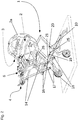
- the Fig. 1 shows a tilting circular saw with a frame 1 on which a saw blade 2, which cannot be recognized under a saw blade cover 2a (in this respect, reference is made to the Figures 3 to 5 referenced), as well as its rotary motor 3 are fixedly attached with horizontal axis of rotation. Furthermore, a rocker 4 is attached to the frame 1, with a cuttings channel 6, which is used to insert cuttings, and a boom 5 which is attached to the frame 1 such that it can be rocked and carries the cuttings channel 6.
- the frame 1 has a structure that can be erected and collapsed in the manner of Nuremberg scissors, with two scissor legs 7, which each have two lower scissor levers 8a, 8b and two upper scissor levers 9a, 9b and are braced together by means of cross members 11, 11a.
- An upwardly projecting motor support 12 is welded to the upper cross member 11 and carries the rotary motor 3 and the saw blade 2 connected to it.
- a standing foot element 13 is also screwed on the underside, which has two standing feet connected via a cross member, the cross member extending in the direction parallel to the horizontal axis of rotation of the saw blade 2 .
- two wheels 13a are attached to the two lower scissor levers 8b, the lower ends of which point towards the side of the cut material receiving channel 6, in order to make it easier to move the tilting circular saw.
- the boom 5 has two boom bars 14 which are connected to one another via a transverse bar 15 and the cut material receiving channel 6 and which are articulated to the frame 1.
- the articulation points are located at the lower end of two rocker bearing webs 17 protruding downward from the two lower scissor levers 8a above a lower scissor hinge, which in FIG Fig. 2 are shown.
- a total of 16, 17, 18 designated bearing arrangement is provided, which on the one hand comprises the rocker bearing webs 17 and bearing axles 18 inserted at their lower ends, on which bearing axles 18 the two cantilever bars 14 are rotatably received and which bearing axles 18 are designed as removable screw bolts.
- the bearing arrangement 16, 17, 18 comprises two inwardly projecting supports 16 on the axes of the central scissor joints between the lower scissor levers 8a and the upper scissor levers 9b, which are designed as rubber support rollers 16 pushed onto the inwardly projecting hinge axes.
- the support rollers 16 thus limit the rocking movement in the direction away from the saw blade 2 to a position which is used for inserting cut material and in which the cut material channel 6 is not penetrated by the saw blade 2.
- the damper rod 27 is attached with its one end to one of the two cantilever bars 14 and its other end in a Fig. 5 eye to be recognized is inserted into a tab 29 of one of the two parallel upper longitudinal struts 9b of the frame 1 and there in turn with an in Fig. 4 designated cotter pin 28 secured.
- An annular spring 26 is wrapped around the damper rod 27 and is also shown in FIG Fig. 2 and is supported at its one end on the bracket 29 on the frame side and at its other end on a corresponding stop on the damper rod on the rocker side and thus biases the rocker away from the saw blade 2 when sawing.
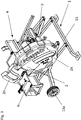
- the frame 1 can be moved from its to the Fig. 1 and 2 shown, upright working position in his in the Figures 3 to 5 shown in the transport position.
- a locking device 10, 19, 20, 21 must be released, which holds the frame in the upright working position.
- the locking device 10, 19, 20, 21 comprises a locking bolt 10, such as in particular the Fig. 2 it can be seen that with its two ends each on one of the associated lower Scissor lever 8a, 8b attached locking axis 19,20 is added. In the position of the locking rod 10 attached to the two lower scissor levers 8a, 8b, a collapse of the frame 1 is thus prevented.
- the motor mount 12 has one in the Fig. 5 to be removed insertion channel or insertion opening 30, through which the corresponding boom 14 can be inserted.
Landscapes
- Life Sciences & Earth Sciences (AREA)
- Engineering & Computer Science (AREA)
- Mechanical Engineering (AREA)
- Wood Science & Technology (AREA)
- Forests & Forestry (AREA)
- Sawing (AREA)
Priority Applications (4)
| Application Number | Priority Date | Filing Date | Title |
|---|---|---|---|
| DK19020060.0T DK3693143T3 (da) | 2019-02-08 | 2019-02-08 | Vipperundsav |
| EP19020060.0A EP3693143B1 (de) | 2019-02-08 | 2019-02-08 | Wippkreissäge |
| CN202010018707.0A CN111546428B (zh) | 2019-02-08 | 2020-01-08 | 摇摆圆锯 |
| AU2020200224A AU2020200224B2 (en) | 2019-02-08 | 2020-01-11 | Rocker Circular Saw |
Applications Claiming Priority (1)
| Application Number | Priority Date | Filing Date | Title |
|---|---|---|---|
| EP19020060.0A EP3693143B1 (de) | 2019-02-08 | 2019-02-08 | Wippkreissäge |
Publications (2)
| Publication Number | Publication Date |
|---|---|
| EP3693143A1 EP3693143A1 (de) | 2020-08-12 |
| EP3693143B1 true EP3693143B1 (de) | 2021-10-20 |
Family
ID=65365769
Family Applications (1)
| Application Number | Title | Priority Date | Filing Date |
|---|---|---|---|
| EP19020060.0A Active EP3693143B1 (de) | 2019-02-08 | 2019-02-08 | Wippkreissäge |
Country Status (4)
| Country | Link |
|---|---|
| EP (1) | EP3693143B1 (da) |
| CN (1) | CN111546428B (da) |
| AU (1) | AU2020200224B2 (da) |
| DK (1) | DK3693143T3 (da) |
Families Citing this family (1)
| Publication number | Priority date | Publication date | Assignee | Title |
|---|---|---|---|---|
| CN113118550A (zh) * | 2021-04-09 | 2021-07-16 | 江西腾江铜业有限公司 | 一种多尺寸铜棒切割机 |
Family Cites Families (12)
| Publication number | Priority date | Publication date | Assignee | Title |
|---|---|---|---|---|
| DE8123262U1 (de) * | 1981-08-07 | 1982-02-18 | Alois Kober KG Maschinenfabrik, 8871 Kötz | Spanabhebende heimwerkermaschien, insbesondere wippsaege |
| DE8327078U1 (de) * | 1983-09-21 | 1983-12-01 | Susemihl, Rolf, 6380 Bad Homburg | Wippsäge |
| US6530583B1 (en) | 2000-05-15 | 2003-03-11 | Mark J. Mueller | Work tool transporting and support apparatus |
| JP2007111945A (ja) * | 2005-10-19 | 2007-05-10 | Makita Corp | 切断機 |
| DE102010014995A1 (de) * | 2010-04-14 | 2012-12-27 | Binderberger Maschinenbau Gmbh | Schneidgutwippe |
| DE202010011450U1 (de) | 2010-05-26 | 2010-12-30 | Scheppach Fabrikation Von Holzbearbeitungsmaschinen Gmbh | Wippkreissäge |
| DE102011117521B3 (de) | 2011-11-03 | 2013-03-07 | Scheppach Fabrikation Von Holzbearbeitungsmaschinen Gmbh | Wippsäge |
| US9186736B1 (en) * | 2014-05-18 | 2015-11-17 | Chin-Chin Chang | Collapsible stand for table saw |
| US9776319B2 (en) * | 2014-09-02 | 2017-10-03 | Black & Decker Inc. | Portable work bench |
| JP6918553B2 (ja) * | 2017-04-05 | 2021-08-11 | 株式会社マキタ | 携帯用加工機 |
| CN107053346A (zh) * | 2017-04-26 | 2017-08-18 | 武汉科技大学 | 一种中纤板锯切方法及锯切装置 |
| CN107511530B (zh) | 2017-09-19 | 2019-01-22 | 安徽机电职业技术学院 | 一种剪式升降锯切机装置 |
-
2019
- 2019-02-08 DK DK19020060.0T patent/DK3693143T3/da active
- 2019-02-08 EP EP19020060.0A patent/EP3693143B1/de active Active
-
2020
- 2020-01-08 CN CN202010018707.0A patent/CN111546428B/zh active Active
- 2020-01-11 AU AU2020200224A patent/AU2020200224B2/en active Active
Also Published As
| Publication number | Publication date |
|---|---|
| DK3693143T3 (da) | 2022-01-17 |
| AU2020200224A1 (en) | 2020-08-27 |
| EP3693143A1 (de) | 2020-08-12 |
| CN111546428B (zh) | 2022-02-18 |
| CN111546428A (zh) | 2020-08-18 |
| AU2020200224B2 (en) | 2021-04-01 |
Similar Documents
| Publication | Publication Date | Title |
|---|---|---|
| EP3656208B1 (de) | Werkzeugarm für arbeiten in schwer zugänglichen positionen | |
| DE3447789A1 (de) | Maehmaschine | |
| DE2418210C2 (de) | Kreiselheuwerbungsmaschine | |
| DE2555632A1 (de) | Auslegeranordnung zum stabilisieren eines fahrzeuges | |
| EP0807377A2 (de) | Vorrichtung zum Anschliessen eines aus der Arbeitsstellung in eine Transportstellung höhenverstellbares Gerätes an ein Fahrzeug | |
| EP3354127A1 (de) | Hoch-entaster | |
| WO2016045666A1 (de) | Vorrichtung zum entfernen der äste von lebenden bäumen | |
| DE8016170U1 (de) | Vorrichtung zum entwurzeln von baumstuempfen | |
| EP3693143B1 (de) | Wippkreissäge | |
| EP2334162A2 (de) | Rasentrimmer | |
| DE2922495A1 (de) | Maehvorrichtung | |
| EP0426005A1 (de) | Kupplungsrahmen | |
| DE1482095C3 (de) | Mähmaschine | |
| DE102010017888B4 (de) | Vorrichtung zum Besteigen und/oder zur Bearbeitung von Stämmen | |
| DE2936688A1 (de) | Zur handhabung schwerer lasten dienende drehbare vorrichtung | |
| DE2117667A1 (de) | Von einem Fahrzeug aufgenommene undangetriebene Rasenmähvorrichtung | |
| WO1994006275A1 (de) | Entaster | |
| EP3479678A1 (de) | Sägevorrichtung zum zuschneiden von pflanzen | |
| DE3448426C3 (de) | Landwirtschaftliche Maschine | |
| EP1830006B1 (de) | Bauarbeitsvorrichtung und Verfahren zur Bereitstellung eines Transportzustands für eine Bauarbeitsvorrichtung | |
| DE69702410T2 (de) | Leiterträger für Fahrzeuge | |
| EP4290014B1 (de) | Gelenkkörper für eine klappbake und klappbake | |
| DE3444412C2 (da) | ||
| DE202011052066U1 (de) | Vorrichtung zum Ernten und Bearbeiten von Baumstämmen | |
| EP4201188A1 (de) | Landwirtschaftliches anbaugerät |
Legal Events
| Date | Code | Title | Description |
|---|---|---|---|
| PUAI | Public reference made under article 153(3) epc to a published international application that has entered the european phase |
Free format text: ORIGINAL CODE: 0009012 |
|
| STAA | Information on the status of an ep patent application or granted ep patent |
Free format text: STATUS: THE APPLICATION HAS BEEN PUBLISHED |
|
| AK | Designated contracting states |
Kind code of ref document: A1 Designated state(s): AL AT BE BG CH CY CZ DE DK EE ES FI FR GB GR HR HU IE IS IT LI LT LU LV MC MK MT NL NO PL PT RO RS SE SI SK SM TR |
|
| AX | Request for extension of the european patent |
Extension state: BA ME |
|
| STAA | Information on the status of an ep patent application or granted ep patent |
Free format text: STATUS: REQUEST FOR EXAMINATION WAS MADE |
|
| 17P | Request for examination filed |
Effective date: 20200814 |
|
| RBV | Designated contracting states (corrected) |
Designated state(s): AL AT BE BG CH CY CZ DE DK EE ES FI FR GB GR HR HU IE IS IT LI LT LU LV MC MK MT NL NO PL PT RO RS SE SI SK SM TR |
|
| GRAP | Despatch of communication of intention to grant a patent |
Free format text: ORIGINAL CODE: EPIDOSNIGR1 |
|
| STAA | Information on the status of an ep patent application or granted ep patent |
Free format text: STATUS: GRANT OF PATENT IS INTENDED |
|
| INTG | Intention to grant announced |
Effective date: 20210118 |
|
| GRAJ | Information related to disapproval of communication of intention to grant by the applicant or resumption of examination proceedings by the epo deleted |
Free format text: ORIGINAL CODE: EPIDOSDIGR1 |
|
| STAA | Information on the status of an ep patent application or granted ep patent |
Free format text: STATUS: REQUEST FOR EXAMINATION WAS MADE |
|
| GRAS | Grant fee paid |
Free format text: ORIGINAL CODE: EPIDOSNIGR3 |
|
| STAA | Information on the status of an ep patent application or granted ep patent |
Free format text: STATUS: GRANT OF PATENT IS INTENDED |
|
| GRAP | Despatch of communication of intention to grant a patent |
Free format text: ORIGINAL CODE: EPIDOSNIGR1 |
|
| INTC | Intention to grant announced (deleted) | ||
| INTG | Intention to grant announced |
Effective date: 20210601 |
|
| GRAA | (expected) grant |
Free format text: ORIGINAL CODE: 0009210 |
|
| STAA | Information on the status of an ep patent application or granted ep patent |
Free format text: STATUS: THE PATENT HAS BEEN GRANTED |
|
| AK | Designated contracting states |
Kind code of ref document: B1 Designated state(s): AL AT BE BG CH CY CZ DE DK EE ES FI FR GB GR HR HU IE IS IT LI LT LU LV MC MK MT NL NO PL PT RO RS SE SI SK SM TR |
|
| REG | Reference to a national code |
Ref country code: GB Ref legal event code: FG4D Free format text: NOT ENGLISH |
|
| REG | Reference to a national code |
Ref country code: CH Ref legal event code: EP |
|
| REG | Reference to a national code |
Ref country code: IE Ref legal event code: FG4D Free format text: LANGUAGE OF EP DOCUMENT: GERMAN |
|
| REG | Reference to a national code |
Ref country code: DE Ref legal event code: R096 Ref document number: 502019002521 Country of ref document: DE |
|
| REG | Reference to a national code |
Ref country code: AT Ref legal event code: REF Ref document number: 1439552 Country of ref document: AT Kind code of ref document: T Effective date: 20211115 |
|
| REG | Reference to a national code |
Ref country code: SE Ref legal event code: TRGR |
|
| REG | Reference to a national code |
Ref country code: FI Ref legal event code: FGE |
|
| REG | Reference to a national code |
Ref country code: DK Ref legal event code: T3 Effective date: 20220110 |
|
| REG | Reference to a national code |
Ref country code: NO Ref legal event code: T2 Effective date: 20211020 |
|
| REG | Reference to a national code |
Ref country code: DE Ref legal event code: R081 Ref document number: 502019002521 Country of ref document: DE Owner name: SCHEPPACH GMBH, DE Free format text: FORMER OWNER: SCHEPPACH FABRIKATION VON HOLZBEARBEITUNGSMASCHINEN GMBH, 89335 ICHENHAUSEN, DE |
|
| REG | Reference to a national code |
Ref country code: LT Ref legal event code: MG9D |
|
| RAP4 | Party data changed (patent owner data changed or rights of a patent transferred) |
Owner name: SCHEPPACH GMBH |
|
| REG | Reference to a national code |
Ref country code: NL Ref legal event code: MP Effective date: 20211020 |
|
| RAP4 | Party data changed (patent owner data changed or rights of a patent transferred) |
Owner name: SCHEPPACH GMBH |
|
| PG25 | Lapsed in a contracting state [announced via postgrant information from national office to epo] |
Ref country code: RS Free format text: LAPSE BECAUSE OF FAILURE TO SUBMIT A TRANSLATION OF THE DESCRIPTION OR TO PAY THE FEE WITHIN THE PRESCRIBED TIME-LIMIT Effective date: 20211020 Ref country code: LT Free format text: LAPSE BECAUSE OF FAILURE TO SUBMIT A TRANSLATION OF THE DESCRIPTION OR TO PAY THE FEE WITHIN THE PRESCRIBED TIME-LIMIT Effective date: 20211020 Ref country code: BG Free format text: LAPSE BECAUSE OF FAILURE TO SUBMIT A TRANSLATION OF THE DESCRIPTION OR TO PAY THE FEE WITHIN THE PRESCRIBED TIME-LIMIT Effective date: 20220120 |
|
| PG25 | Lapsed in a contracting state [announced via postgrant information from national office to epo] |
Ref country code: IS Free format text: LAPSE BECAUSE OF FAILURE TO SUBMIT A TRANSLATION OF THE DESCRIPTION OR TO PAY THE FEE WITHIN THE PRESCRIBED TIME-LIMIT Effective date: 20220220 Ref country code: PT Free format text: LAPSE BECAUSE OF FAILURE TO SUBMIT A TRANSLATION OF THE DESCRIPTION OR TO PAY THE FEE WITHIN THE PRESCRIBED TIME-LIMIT Effective date: 20220221 Ref country code: PL Free format text: LAPSE BECAUSE OF FAILURE TO SUBMIT A TRANSLATION OF THE DESCRIPTION OR TO PAY THE FEE WITHIN THE PRESCRIBED TIME-LIMIT Effective date: 20211020 Ref country code: NL Free format text: LAPSE BECAUSE OF FAILURE TO SUBMIT A TRANSLATION OF THE DESCRIPTION OR TO PAY THE FEE WITHIN THE PRESCRIBED TIME-LIMIT Effective date: 20211020 Ref country code: LV Free format text: LAPSE BECAUSE OF FAILURE TO SUBMIT A TRANSLATION OF THE DESCRIPTION OR TO PAY THE FEE WITHIN THE PRESCRIBED TIME-LIMIT Effective date: 20211020 Ref country code: HR Free format text: LAPSE BECAUSE OF FAILURE TO SUBMIT A TRANSLATION OF THE DESCRIPTION OR TO PAY THE FEE WITHIN THE PRESCRIBED TIME-LIMIT Effective date: 20211020 Ref country code: GR Free format text: LAPSE BECAUSE OF FAILURE TO SUBMIT A TRANSLATION OF THE DESCRIPTION OR TO PAY THE FEE WITHIN THE PRESCRIBED TIME-LIMIT Effective date: 20220121 Ref country code: ES Free format text: LAPSE BECAUSE OF FAILURE TO SUBMIT A TRANSLATION OF THE DESCRIPTION OR TO PAY THE FEE WITHIN THE PRESCRIBED TIME-LIMIT Effective date: 20211020 |
|
| REG | Reference to a national code |
Ref country code: FI Ref legal event code: PCE Owner name: SCHEPPACH GMBH |
|
| REG | Reference to a national code |
Ref country code: DE Ref legal event code: R097 Ref document number: 502019002521 Country of ref document: DE |
|
| PG25 | Lapsed in a contracting state [announced via postgrant information from national office to epo] |
Ref country code: SM Free format text: LAPSE BECAUSE OF FAILURE TO SUBMIT A TRANSLATION OF THE DESCRIPTION OR TO PAY THE FEE WITHIN THE PRESCRIBED TIME-LIMIT Effective date: 20211020 Ref country code: SK Free format text: LAPSE BECAUSE OF FAILURE TO SUBMIT A TRANSLATION OF THE DESCRIPTION OR TO PAY THE FEE WITHIN THE PRESCRIBED TIME-LIMIT Effective date: 20211020 Ref country code: RO Free format text: LAPSE BECAUSE OF FAILURE TO SUBMIT A TRANSLATION OF THE DESCRIPTION OR TO PAY THE FEE WITHIN THE PRESCRIBED TIME-LIMIT Effective date: 20211020 Ref country code: EE Free format text: LAPSE BECAUSE OF FAILURE TO SUBMIT A TRANSLATION OF THE DESCRIPTION OR TO PAY THE FEE WITHIN THE PRESCRIBED TIME-LIMIT Effective date: 20211020 Ref country code: CZ Free format text: LAPSE BECAUSE OF FAILURE TO SUBMIT A TRANSLATION OF THE DESCRIPTION OR TO PAY THE FEE WITHIN THE PRESCRIBED TIME-LIMIT Effective date: 20211020 |
|
| PLBE | No opposition filed within time limit |
Free format text: ORIGINAL CODE: 0009261 |
|
| STAA | Information on the status of an ep patent application or granted ep patent |
Free format text: STATUS: NO OPPOSITION FILED WITHIN TIME LIMIT |
|
| 26N | No opposition filed |
Effective date: 20220721 |
|
| PG25 | Lapsed in a contracting state [announced via postgrant information from national office to epo] |
Ref country code: MC Free format text: LAPSE BECAUSE OF FAILURE TO SUBMIT A TRANSLATION OF THE DESCRIPTION OR TO PAY THE FEE WITHIN THE PRESCRIBED TIME-LIMIT Effective date: 20211020 |
|
| REG | Reference to a national code |
Ref country code: CH Ref legal event code: PL |
|
| REG | Reference to a national code |
Ref country code: AT Ref legal event code: HC Ref document number: 1439552 Country of ref document: AT Kind code of ref document: T Owner name: SCHEPPACH GMBH, DE Effective date: 20220906 |
|
| REG | Reference to a national code |
Ref country code: BE Ref legal event code: MM Effective date: 20220228 |
|
| PG25 | Lapsed in a contracting state [announced via postgrant information from national office to epo] |
Ref country code: LU Free format text: LAPSE BECAUSE OF NON-PAYMENT OF DUE FEES Effective date: 20220208 Ref country code: AL Free format text: LAPSE BECAUSE OF FAILURE TO SUBMIT A TRANSLATION OF THE DESCRIPTION OR TO PAY THE FEE WITHIN THE PRESCRIBED TIME-LIMIT Effective date: 20211020 |
|
| PG25 | Lapsed in a contracting state [announced via postgrant information from national office to epo] |
Ref country code: SI Free format text: LAPSE BECAUSE OF FAILURE TO SUBMIT A TRANSLATION OF THE DESCRIPTION OR TO PAY THE FEE WITHIN THE PRESCRIBED TIME-LIMIT Effective date: 20211020 |
|
| PG25 | Lapsed in a contracting state [announced via postgrant information from national office to epo] |
Ref country code: LI Free format text: LAPSE BECAUSE OF NON-PAYMENT OF DUE FEES Effective date: 20220228 Ref country code: IE Free format text: LAPSE BECAUSE OF NON-PAYMENT OF DUE FEES Effective date: 20220208 Ref country code: CH Free format text: LAPSE BECAUSE OF NON-PAYMENT OF DUE FEES Effective date: 20220228 |
|
| PG25 | Lapsed in a contracting state [announced via postgrant information from national office to epo] |
Ref country code: BE Free format text: LAPSE BECAUSE OF NON-PAYMENT OF DUE FEES Effective date: 20220228 |
|
| PG25 | Lapsed in a contracting state [announced via postgrant information from national office to epo] |
Ref country code: IT Free format text: LAPSE BECAUSE OF FAILURE TO SUBMIT A TRANSLATION OF THE DESCRIPTION OR TO PAY THE FEE WITHIN THE PRESCRIBED TIME-LIMIT Effective date: 20211020 |
|
| P01 | Opt-out of the competence of the unified patent court (upc) registered |
Effective date: 20230603 |
|
| GBPC | Gb: european patent ceased through non-payment of renewal fee |
Effective date: 20230208 |
|
| PG25 | Lapsed in a contracting state [announced via postgrant information from national office to epo] |
Ref country code: GB Free format text: LAPSE BECAUSE OF NON-PAYMENT OF DUE FEES Effective date: 20230208 |
|
| PG25 | Lapsed in a contracting state [announced via postgrant information from national office to epo] |
Ref country code: GB Free format text: LAPSE BECAUSE OF NON-PAYMENT OF DUE FEES Effective date: 20230208 |
|
| PG25 | Lapsed in a contracting state [announced via postgrant information from national office to epo] |
Ref country code: MK Free format text: LAPSE BECAUSE OF FAILURE TO SUBMIT A TRANSLATION OF THE DESCRIPTION OR TO PAY THE FEE WITHIN THE PRESCRIBED TIME-LIMIT Effective date: 20211020 Ref country code: CY Free format text: LAPSE BECAUSE OF FAILURE TO SUBMIT A TRANSLATION OF THE DESCRIPTION OR TO PAY THE FEE WITHIN THE PRESCRIBED TIME-LIMIT Effective date: 20211020 |
|
| PG25 | Lapsed in a contracting state [announced via postgrant information from national office to epo] |
Ref country code: HU Free format text: LAPSE BECAUSE OF FAILURE TO SUBMIT A TRANSLATION OF THE DESCRIPTION OR TO PAY THE FEE WITHIN THE PRESCRIBED TIME-LIMIT; INVALID AB INITIO Effective date: 20190208 |
|
| PG25 | Lapsed in a contracting state [announced via postgrant information from national office to epo] |
Ref country code: TR Free format text: LAPSE BECAUSE OF FAILURE TO SUBMIT A TRANSLATION OF THE DESCRIPTION OR TO PAY THE FEE WITHIN THE PRESCRIBED TIME-LIMIT Effective date: 20211020 |
|
| PG25 | Lapsed in a contracting state [announced via postgrant information from national office to epo] |
Ref country code: MT Free format text: LAPSE BECAUSE OF FAILURE TO SUBMIT A TRANSLATION OF THE DESCRIPTION OR TO PAY THE FEE WITHIN THE PRESCRIBED TIME-LIMIT Effective date: 20211020 |
|
| PGFP | Annual fee paid to national office [announced via postgrant information from national office to epo] |
Ref country code: SE Payment date: 20260218 Year of fee payment: 8 |
|
| PGFP | Annual fee paid to national office [announced via postgrant information from national office to epo] |
Ref country code: DE Payment date: 20260228 Year of fee payment: 8 Ref country code: DK Payment date: 20260217 Year of fee payment: 8 Ref country code: NO Payment date: 20260217 Year of fee payment: 8 |
|
| PGFP | Annual fee paid to national office [announced via postgrant information from national office to epo] |
Ref country code: AT Payment date: 20260216 Year of fee payment: 8 |
|
| PGFP | Annual fee paid to national office [announced via postgrant information from national office to epo] |
Ref country code: FI Payment date: 20260217 Year of fee payment: 8 |
|
| PGFP | Annual fee paid to national office [announced via postgrant information from national office to epo] |
Ref country code: FR Payment date: 20260219 Year of fee payment: 8 |