EP3693182B1 - Mutternsicherungsvorrichtung zur befestigung von rädern oder dergleichen - Google Patents
Mutternsicherungsvorrichtung zur befestigung von rädern oder dergleichen Download PDFInfo
- Publication number
- EP3693182B1 EP3693182B1 EP19155905.3A EP19155905A EP3693182B1 EP 3693182 B1 EP3693182 B1 EP 3693182B1 EP 19155905 A EP19155905 A EP 19155905A EP 3693182 B1 EP3693182 B1 EP 3693182B1
- Authority
- EP
- European Patent Office
- Prior art keywords
- locking device
- nut locking
- nut
- nuts
- portions
- Prior art date
- Legal status (The legal status is an assumption and is not a legal conclusion. Google has not performed a legal analysis and makes no representation as to the accuracy of the status listed.)
- Active
Links
Images




Classifications
-
- B—PERFORMING OPERATIONS; TRANSPORTING
- B60—VEHICLES IN GENERAL
- B60B—VEHICLE WHEELS; CASTORS; AXLES FOR WHEELS OR CASTORS; INCREASING WHEEL ADHESION
- B60B3/00—Disc wheels, i.e. wheels with load-supporting disc body
- B60B3/14—Attaching disc body to hub ; Wheel adapters
- B60B3/16—Attaching disc body to hub ; Wheel adapters by bolts or the like
- B60B3/165—Attaching disc body to hub ; Wheel adapters by bolts or the like with locking devices for the fixing means, e.g. screw or nut covers
-
- F—MECHANICAL ENGINEERING; LIGHTING; HEATING; WEAPONS; BLASTING
- F16—ENGINEERING ELEMENTS AND UNITS; GENERAL MEASURES FOR PRODUCING AND MAINTAINING EFFECTIVE FUNCTIONING OF MACHINES OR INSTALLATIONS; THERMAL INSULATION IN GENERAL
- F16B—DEVICES FOR FASTENING OR SECURING CONSTRUCTIONAL ELEMENTS OR MACHINE PARTS TOGETHER, e.g. NAILS, BOLTS, CIRCLIPS, CLAMPS, CLIPS OR WEDGES; JOINTS OR JOINTING
- F16B39/00—Locking of screws, bolts or nuts
- F16B39/02—Locking of screws, bolts or nuts in which the locking takes place after screwing down
- F16B39/10—Locking of screws, bolts or nuts in which the locking takes place after screwing down by a plate, spring, wire or ring immovable with regard to the bolt or object and mainly perpendicular to the axis of the bolt
- F16B39/101—Locking of screws, bolts or nuts in which the locking takes place after screwing down by a plate, spring, wire or ring immovable with regard to the bolt or object and mainly perpendicular to the axis of the bolt with a plate, spring, wire or ring holding two or more nuts or bolt heads which are mainly in the same plane
-
- B—PERFORMING OPERATIONS; TRANSPORTING
- B60—VEHICLES IN GENERAL
- B60B—VEHICLE WHEELS; CASTORS; AXLES FOR WHEELS OR CASTORS; INCREASING WHEEL ADHESION
- B60B2900/00—Purpose of invention
- B60B2900/30—Increase in
- B60B2900/331—Safety or security
- B60B2900/3312—Safety or security during regular use
Definitions
- the present invention relates to a nut locking device, for fastening wheels or similar, to a method of producing the nut locking device and use thereof.
- the present invention thus solves one or more of the problems set out above by providing according to a first aspect of the present invention a nut locking device for locking at least two nuts to prevent them from turning, said nut locking device having an inner side and an outer side, wherein said nut locking device comprises:
- Said nuts are preferably nuts adapted for usage together with wheels for fastening said wheels (which wheels preferably have tires and rims), which wheels preferably are mounted on a vehicle.
- step i) the moldable material may be conveyed through an inlet to said mold.
- step iii) said nut locking device is finalized (through the separation of said mold from said nut locking device) and becomes ready for final usage (which also additionally may involve a further leveling step of the final product, before usage, to get rid of any superfluous solidified moldable material).
- a nut locking device according to the first aspect, or provided through the process according to the second aspect, for locking nuts at wheels, preferably mounted on a vehicle. Through using said device the wheel is better fastened via its nuts.
- nut embraces any nut which could appear on wheels (with tires). These wheels (with tires) may e.g. be adapted for use on vehicles, such as on a commercial vehicle or on cars.
- the nut may further e.g. be a wheel-nut (also called lug nut).
- the device according to the first aspect may be especially useful for use on wheels (with tires) when mounted on a commercial vehicle, such as on a truck/lorry, on a bus or on a similar vehicle.
- said surface is flat or convex or a combination thereof.
- said at least two nuts are wheel-nuts.
- said at least one connecting portion is a U-shaped solid body.
- said inner side of said nut locking device is a wheel-facing side.
- said nut locking device comprises a plurality of locking portions for locking a plurality of nuts, such as at least 6, 8 or 10 nuts.
- said nut locking device is annular, and wherein each locking portion is connected to at least two neighbouring locking portions.
- each one of said connecting portions comprises a reinforcement portion.
- said reinforcement portion comprises a resilient material.
- the reinforcement comprising the resilient material may have essentially triangular shape or an essentially rectangular shape.
- each locking portion comprises a plurality of protrusions extending radially inwards from an inner wall of said through hole.
- said device comprises a plastic material, preferably one or more polyolefins or a combination thereof, most preferred combined with a reinforcing material such as a material from the group comprising reinforcing glass, cellulose fibres, wood fibres, or combinations thereof, and/or other additives.
- a reinforcing material such as a material from the group comprising reinforcing glass, cellulose fibres, wood fibres, or combinations thereof, and/or other additives.
- Said additives may be e.g. UV-protection agents (such as carbon black) and/or antistatic agents.
- said plastic material is selected from the group consisting of PP (polypropylene), PE (polyethylene, such as TPE and LDPE), or a combination thereof.
- the inner side of the at least two locking portions and the inner side of the at least one connecting portion are arranged in a single geometric plane.
- the outer side of the at least two locking portions and the outer side of the at least one connecting portion are arranged in a single geometric plane.
- a nut locking device may be made through a process whereby a moldable material is fed into a mold.
- the mold may have two parts that may be separable from each other. Subsequently an injection molding of said material is done providing a nut locking device according to the first aspect. To give rise to a useable product said nut locking device is separated from said mold, thus providing said nut locking device.
- the mold may also have two or more parts.
- the moldable material may be a plastic material and may be one or a combination of PP and PE (such as TPE and LDPE).
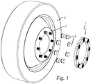
- figure 1 it is shown how the embodiment (1) with 8 holes adapted to receive 8 nuts (5) is fastened and thus applied to a wheel (with a tire) (6), and particularly how it is positioned in relationship to the rim (7) of said wheel.
- the wheel may further be fastened to a lorry/truck, a bus or a car, or to any other type of vehicle.
- the wheel is better fastened via its nuts when using said device.
- the wheel is better anchored in an indirect way through the usage of said device, as said device prevents the nuts fastened at the wheel from turning.
- Figure 2 disclose an embodiment (10) with 2 holes (11a, 11b) adapted to receive 2 nuts.
- the protrusions in the hole can clearly be seen for anchoring the nut.
- the connecting portion (12) is positioned between said holes. in Fig 2a it can be seen from a top perspective whereas it can be seen from a bottom perspective in Fig 2b .
- the protrusions (8) in the holes can clearly be seen for anchoring the nuts (5).
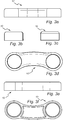
- Figures 3 discloses as said, an embodiment (10) with 2 holes adapted to receive 2 nuts.
- Fig 3a, 3b, 3c and 3e you can see it from different side views.
- Fig 3d it can be seen from the top.
- Fig 3f it can be seen from the bottom.
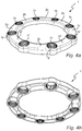
- Figure 4 discloses as said above an embodiment (1) with 8 holes (1a, 1b, 1c, 1d, 1e, 1f, 1g and 1h) adapted to receive 8 nuts and in Fig 4a it can be seen from a top perspective whereas it can be seen from a bottom perspective in Fig 4b .
- the connecting portions (2a, 2b, 2c, 2d, 2e, 2f, 2g and 2h) are positioned between said holes.
- the protrusions (8) in the holes can also clearly be seen for anchoring the nuts (5) (c.f. Fig. 2 ).
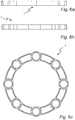
- Figure 5 discloses as said above an embodiment (1) with 8 holes adapted to receive 8 nuts and in Fig 5a it can be seen from the top. In Fig 5b and 5c you can see it from the side.
- Figure 6 discloses as said above also an embodiment (1) with 8 holes adapted to receive 8 nuts and in Fig 6a and 6b you can see it from the side. In Fig 6c it can be seen from the bottom.
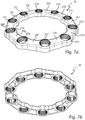
- Figure 7 discloses as said above an embodiment (20) with 10 holes (21a, 21b, 21c, 21d, 21e, 21f, 21g, 21h, 21i and 21j) adapted to receive 10 nuts and in Fig 7a it can be seen from a top perspective whereas it can be seen from a bottom perspective in Fig 7b .
- the connecting portions (22a, 22b, 22c, 22d, 22e, 22f, 22g, 22h, 22i and 22j) are positioned between said holes.
- the protrusions (8) in the holes can also clearly be seen for anchoring the nuts (5) (c.f. Fig. 2 ).
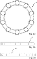
- Figure 8 discloses as said above an embodiment (20) with 10 holes adapted to receive 10 nuts and in Fig 8a it can be seen from the top. In Fig 8b and 8c you can see it from the side.
- Figure 9 discloses as said above also an embodiment (20) with 10 holes adapted to receive 10 nuts and in Fig 9a and 9b you can see it from the side. In Fig 9c it can be seen from the bottom.
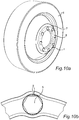
- Figure 10 discloses how the embodiment (1) with 8 holes adapted to receive 8 nuts (5) has been fastened ( Fig. 10a ) on a wheel (with a tire) (6). Also the position of said device in relation to the rim (7) of said wheel can also be seen. In particular, in Figure 10b the protrusions (8) in the hole can clearly be seen for anchoring the nut (5).
- Figures 11 show two variants of reinforcements which may be made from a resilient material. One is essentially triangular which can be seen in Fig 11a with details 3a and 3b, and the other one rectangular which can be seen in Fig. 11b with detail 3. In figures 11a and 11b the protrusions (8) in the holes can also clearly be seen for anchoring the nuts (5).
Landscapes
- Engineering & Computer Science (AREA)
- Mechanical Engineering (AREA)
- General Engineering & Computer Science (AREA)
- Connection Of Plates (AREA)
- Refuge Islands, Traffic Blockers, Or Guard Fence (AREA)
Claims (15)
- Mutternsicherungsvorrichtung zum Sichern von mindestens zwei Muttern (5), um ein Verdrehen zu verhindern, wobei die Mutternsicherungsvorrichtung eine Innenseite und eine Außenseite aufweist, wobei die Mutternsicherungsvorrichtung umfasst:mindestens zwei Sicherungsabschnitte, wobei jeder der mindestens zwei Sicherungsabschnitte mit einem Durchgangsloch (11a, 11b; 1a, 1b, 1c, 1d, 1e, 1f, 1g,1h; 21a, 21b, 21c, 21d, 21e, 21f, 21g, 21h, 21i, 21j) versehen ist, das dazu konfiguriert ist, eine Mutter zu umgeben,mindestens einen Verbindungsabschnitt (12; 2a, 2b, 2c, 2d, 2e, 2f, 2g, 2h; 22a, 22b, 22c, 22d, 22e, 22f, 22g, 22h, 22i, 22j), der mindestens zwei der Sicherungsabschnitte verbindet, wobei eine Außenseite des Verbindungsabschnitts eine Fläche umfasst, die sich in einer Ebene erstreckt, die senkrecht zu einer Mittelachse der Durchgangslöcher ist und mindestens zwei Muttern Radmuttern sind, dadurch gekennzeichnet, dass der mindestens eine Verbindungsabschnitt ein U-förmiger Körper ist.
- Mutternsicherungsvorrichtung nach Anspruch 1, wobei die Oberfläche flach oder konvex oder eine Kombination davon ist.
- Mutternsicherungsvorrichtung nach einem der vorhergehenden Ansprüche, wobei der mindestens eine Verbindungsabschnitt ein Vollkörper oder ein Hohlkörper ist.
- Mutternsicherungsvorrichtung nach einem der vorhergehenden Ansprüche, wobei die Innenseite der Mutternsicherungsvorrichtung eine dem Rad zugewandte Seite ist.
- Mutternsicherungsvorrichtung nach einem der vorhergehenden Ansprüche, wobei die Vorrichtung eine Mehrzahl von Sicherungsabschnitten zum Verriegeln einer Mehrzahl von Muttern umfasst, wie beispielsweise mindestens 6, 8 oder 10 Muttern.
- Mutternsicherungsvorrichtung nach einem der vorhergehenden Ansprüche, wobei die Vorrichtung ringförmig ist und wobei jeder Sicherungsabschnitte mit mindestens zwei benachbarten Sicherungsabschnitten verbunden ist.
- Mutternsicherungsvorrichtung nach einem der vorhergehenden Ansprüche, wobei jeder der Verbindungsabschnitte einen Verstärkungsabschnitt (3; 3a, 3b) umfasst.
- Mutternsicherungsvorrichtung nach Anspruch 7, wobei der Verstärkungsabschnitt ein elastisches Material umfasst.
- Mutternsicherungsvorrichtung nach einem der vorhergehenden Ansprüche, wobei jeder Sicherungsabschnitt eine Vielzahl von Vorsprüngen (8) umfasst, die sich von einer Innenwand des Durchgangslochs radial nach innen erstrecken.
- Mutternsicherungsvorrichtung nach einem der vorhergehenden Ansprüche, wobei die Vorrichtung ein Kunststoffmaterial umfasst, vorzugsweise ein oder mehrere Polyolefine oder eine Kombination davon, am meisten bevorzugt kombiniert mit einem Verstärkungsmaterial und/oder anderen Additiven.
- Mutternsicherungsvorrichtung nach Anspruch 10, wobei das Kunststoffmaterial ausgewählt ist aus der Gruppe bestehend aus PP, PE oder einer Kombination davon.
- Mutternsicherungsvorrichtung nach einem der vorhergehenden Ansprüche, wobei die Innenseite der mindestens zwei Sicherungsabschnitte und die Innenseite des mindestens einen Verbindungsabschnitts in einer einzigen geometrischen Ebene angeordnet sind.
- Mutternsicherungsvorrichtung nach einem der vorhergehenden Ansprüche, wobei die Außenseite der mindestens zwei Sicherungsabschnitte und die Außenseite des mindestens einen Verbindungsabschnitts in einer einzigen geometrischen Ebene angeordnet sind.
- Verfahren zur Herstellung einer Mutternsicherungsvorrichtung nach einem der vorhergehenden Ansprüche, umfassend die folgenden Schritte:i) Bereitstellen eines formbaren Materials in eine Form,ii) Spritzgießen des Materials, wodurch eine Mutternsicherungsvorrichtung bereitgestellt wird, undiii) Trennen der Mutternsicherungsvorrichtung von der Form, wodurch die Mutternsicherungsvorrichtung bereitgestellt wird.
- Verwendung einer Mutternsicherungsvorrichtung nach einem der Ansprüche 1 bis 13 oder bereitgestellt durch das Verfahren nach Anspruch 14 zum Sichern von Muttern an Rädern, die vorzugsweise an einem Fahrzeug montiert sind.
Priority Applications (1)
| Application Number | Priority Date | Filing Date | Title |
|---|---|---|---|
| EP19155905.3A EP3693182B1 (de) | 2019-02-07 | 2019-02-07 | Mutternsicherungsvorrichtung zur befestigung von rädern oder dergleichen |
Applications Claiming Priority (1)
| Application Number | Priority Date | Filing Date | Title |
|---|---|---|---|
| EP19155905.3A EP3693182B1 (de) | 2019-02-07 | 2019-02-07 | Mutternsicherungsvorrichtung zur befestigung von rädern oder dergleichen |
Publications (2)
| Publication Number | Publication Date |
|---|---|
| EP3693182A1 EP3693182A1 (de) | 2020-08-12 |
| EP3693182B1 true EP3693182B1 (de) | 2021-10-27 |
Family
ID=65363115
Family Applications (1)
| Application Number | Title | Priority Date | Filing Date |
|---|---|---|---|
| EP19155905.3A Active EP3693182B1 (de) | 2019-02-07 | 2019-02-07 | Mutternsicherungsvorrichtung zur befestigung von rädern oder dergleichen |
Country Status (1)
| Country | Link |
|---|---|
| EP (1) | EP3693182B1 (de) |
Families Citing this family (1)
| Publication number | Priority date | Publication date | Assignee | Title |
|---|---|---|---|---|
| WO2026163571A1 (ja) * | 2025-01-31 | 2026-08-06 | 株式会社ニフコ | 緩み表示器 |
Family Cites Families (5)
| Publication number | Priority date | Publication date | Assignee | Title |
|---|---|---|---|---|
| SE436334B (sv) * | 1981-12-14 | 1984-12-03 | Rolf Olsson | Las-eller sekerhetsanordning for bultforband |
| US5429465A (en) * | 1994-04-04 | 1995-07-04 | Witco Corporation | Retainer structure for preventing relative rotation between fastener elements |
| US8011739B2 (en) * | 2006-09-13 | 2011-09-06 | Wirtgen Gmbh | Replaceable wear pad |
| CA2637356C (en) * | 2008-07-10 | 2014-04-15 | Ifor C. Davies | Wheel lug nut locking device |
| SE1650315A1 (en) * | 2016-03-09 | 2017-04-04 | Safety Seal Europe Ab | Wheel-nut locking clamp |
-
2019
- 2019-02-07 EP EP19155905.3A patent/EP3693182B1/de active Active
Also Published As
| Publication number | Publication date |
|---|---|
| EP3693182A1 (de) | 2020-08-12 |
Similar Documents
| Publication | Publication Date | Title |
|---|---|---|
| US10654311B2 (en) | Center lock simulated cap assembly for an automobile wheel | |
| US4793659A (en) | Spoked wheel of synthetic material and method of making therefor | |
| CN109795145A (zh) | 无气式轮胎制造方法 | |
| US20040095014A1 (en) | Base for a rim of a wheel and a rim having such a base | |
| US10493797B2 (en) | Truck wheel | |
| CN104884238A (zh) | 用于模制非充气轮胎的系统和方法 | |
| WO2018112333A1 (en) | Alloy composite road wheel for a vehicle | |
| EP3686032B1 (de) | Luftloser reifen | |
| WO2012048511A1 (zh) | 多腔防爆轮胎及轮毂 | |
| US4420190A (en) | Cast vehicle wheel | |
| CN101309805A (zh) | 挠性非充气轮胎 | |
| EP3693182A1 (de) | Mutternsicherungsvorrichtung zur befestigung von rädern oder dergleichen | |
| JP2002517345A (ja) | 長期輸送時における軽金属製リムを持つ車両ホイール用カバー | |
| JP2007091155A (ja) | タイヤおよびタイヤ成形用金型 | |
| GB1571902A (en) | Method of manufactureof steering wheel | |
| US20090302669A1 (en) | Vehicle Wheel Cover Retention System and Method for Producing Same | |
| CN112770916A (zh) | 车轮以及制造和使用车轮的方法 | |
| WO2017176589A1 (en) | Tire with high strength corrugated sidewalls | |
| KR200483086Y1 (ko) | 비공기압식 발포고무타이어 | |
| JP4070308B2 (ja) | トレッド・パターンから延長して延びる溝がサイドウオールの表面に形成された空気入りタイヤ | |
| JPS6136004A (ja) | 車両用車輪 | |
| EP0232942B1 (de) | Radzierblende mit Befestigungsteilen zum Aufmontieren dieser an ein Kraftfahrzeugrad und seine entsprechende Radnabe | |
| JPH02225016A (ja) | 金属―エラストマー複合スタイル化ホイール及びその成形方法及び装置 | |
| CZ285837B6 (cs) | Vozidlové kolo opatřené pneumatikou | |
| CN209667244U (zh) | 汽车备胎舱结构及汽车 |
Legal Events
| Date | Code | Title | Description |
|---|---|---|---|
| PUAI | Public reference made under article 153(3) epc to a published international application that has entered the european phase |
Free format text: ORIGINAL CODE: 0009012 |
|
| STAA | Information on the status of an ep patent application or granted ep patent |
Free format text: STATUS: THE APPLICATION HAS BEEN PUBLISHED |
|
| AK | Designated contracting states |
Kind code of ref document: A1 Designated state(s): AL AT BE BG CH CY CZ DE DK EE ES FI FR GB GR HR HU IE IS IT LI LT LU LV MC MK MT NL NO PL PT RO RS SE SI SK SM TR |
|
| AX | Request for extension of the european patent |
Extension state: BA ME |
|
| STAA | Information on the status of an ep patent application or granted ep patent |
Free format text: STATUS: REQUEST FOR EXAMINATION WAS MADE |
|
| 17P | Request for examination filed |
Effective date: 20210208 |
|
| RBV | Designated contracting states (corrected) |
Designated state(s): AL AT BE BG CH CY CZ DE DK EE ES FI FR GB GR HR HU IE IS IT LI LT LU LV MC MK MT NL NO PL PT RO RS SE SI SK SM TR |
|
| GRAP | Despatch of communication of intention to grant a patent |
Free format text: ORIGINAL CODE: EPIDOSNIGR1 |
|
| STAA | Information on the status of an ep patent application or granted ep patent |
Free format text: STATUS: GRANT OF PATENT IS INTENDED |
|
| INTG | Intention to grant announced |
Effective date: 20210519 |
|
| GRAS | Grant fee paid |
Free format text: ORIGINAL CODE: EPIDOSNIGR3 |
|
| GRAA | (expected) grant |
Free format text: ORIGINAL CODE: 0009210 |
|
| STAA | Information on the status of an ep patent application or granted ep patent |
Free format text: STATUS: THE PATENT HAS BEEN GRANTED |
|
| AK | Designated contracting states |
Kind code of ref document: B1 Designated state(s): AL AT BE BG CH CY CZ DE DK EE ES FI FR GB GR HR HU IE IS IT LI LT LU LV MC MK MT NL NO PL PT RO RS SE SI SK SM TR |
|
| REG | Reference to a national code |
Ref country code: GB Ref legal event code: FG4D |
|
| REG | Reference to a national code |
Ref country code: CH Ref legal event code: EP |
|
| REG | Reference to a national code |
Ref country code: AT Ref legal event code: REF Ref document number: 1441466 Country of ref document: AT Kind code of ref document: T Effective date: 20211115 |
|
| REG | Reference to a national code |
Ref country code: DE Ref legal event code: R096 Ref document number: 602019008583 Country of ref document: DE |
|
| REG | Reference to a national code |
Ref country code: IE Ref legal event code: FG4D |
|
| REG | Reference to a national code |
Ref country code: NL Ref legal event code: FP |
|
| REG | Reference to a national code |
Ref country code: LT Ref legal event code: MG9D |
|
| REG | Reference to a national code |
Ref country code: AT Ref legal event code: MK05 Ref document number: 1441466 Country of ref document: AT Kind code of ref document: T Effective date: 20211027 |
|
| PG25 | Lapsed in a contracting state [announced via postgrant information from national office to epo] |
Ref country code: RS Free format text: LAPSE BECAUSE OF FAILURE TO SUBMIT A TRANSLATION OF THE DESCRIPTION OR TO PAY THE FEE WITHIN THE PRESCRIBED TIME-LIMIT Effective date: 20211027 Ref country code: LT Free format text: LAPSE BECAUSE OF FAILURE TO SUBMIT A TRANSLATION OF THE DESCRIPTION OR TO PAY THE FEE WITHIN THE PRESCRIBED TIME-LIMIT Effective date: 20211027 Ref country code: FI Free format text: LAPSE BECAUSE OF FAILURE TO SUBMIT A TRANSLATION OF THE DESCRIPTION OR TO PAY THE FEE WITHIN THE PRESCRIBED TIME-LIMIT Effective date: 20211027 Ref country code: BG Free format text: LAPSE BECAUSE OF FAILURE TO SUBMIT A TRANSLATION OF THE DESCRIPTION OR TO PAY THE FEE WITHIN THE PRESCRIBED TIME-LIMIT Effective date: 20220127 Ref country code: AT Free format text: LAPSE BECAUSE OF FAILURE TO SUBMIT A TRANSLATION OF THE DESCRIPTION OR TO PAY THE FEE WITHIN THE PRESCRIBED TIME-LIMIT Effective date: 20211027 |
|
| PG25 | Lapsed in a contracting state [announced via postgrant information from national office to epo] |
Ref country code: IS Free format text: LAPSE BECAUSE OF FAILURE TO SUBMIT A TRANSLATION OF THE DESCRIPTION OR TO PAY THE FEE WITHIN THE PRESCRIBED TIME-LIMIT Effective date: 20220227 Ref country code: SE Free format text: LAPSE BECAUSE OF FAILURE TO SUBMIT A TRANSLATION OF THE DESCRIPTION OR TO PAY THE FEE WITHIN THE PRESCRIBED TIME-LIMIT Effective date: 20211027 Ref country code: PT Free format text: LAPSE BECAUSE OF FAILURE TO SUBMIT A TRANSLATION OF THE DESCRIPTION OR TO PAY THE FEE WITHIN THE PRESCRIBED TIME-LIMIT Effective date: 20220228 Ref country code: PL Free format text: LAPSE BECAUSE OF FAILURE TO SUBMIT A TRANSLATION OF THE DESCRIPTION OR TO PAY THE FEE WITHIN THE PRESCRIBED TIME-LIMIT Effective date: 20211027 Ref country code: NO Free format text: LAPSE BECAUSE OF FAILURE TO SUBMIT A TRANSLATION OF THE DESCRIPTION OR TO PAY THE FEE WITHIN THE PRESCRIBED TIME-LIMIT Effective date: 20220127 Ref country code: LV Free format text: LAPSE BECAUSE OF FAILURE TO SUBMIT A TRANSLATION OF THE DESCRIPTION OR TO PAY THE FEE WITHIN THE PRESCRIBED TIME-LIMIT Effective date: 20211027 Ref country code: HR Free format text: LAPSE BECAUSE OF FAILURE TO SUBMIT A TRANSLATION OF THE DESCRIPTION OR TO PAY THE FEE WITHIN THE PRESCRIBED TIME-LIMIT Effective date: 20211027 Ref country code: GR Free format text: LAPSE BECAUSE OF FAILURE TO SUBMIT A TRANSLATION OF THE DESCRIPTION OR TO PAY THE FEE WITHIN THE PRESCRIBED TIME-LIMIT Effective date: 20220128 Ref country code: ES Free format text: LAPSE BECAUSE OF FAILURE TO SUBMIT A TRANSLATION OF THE DESCRIPTION OR TO PAY THE FEE WITHIN THE PRESCRIBED TIME-LIMIT Effective date: 20211027 |
|
| REG | Reference to a national code |
Ref country code: DE Ref legal event code: R097 Ref document number: 602019008583 Country of ref document: DE |
|
| PG25 | Lapsed in a contracting state [announced via postgrant information from national office to epo] |
Ref country code: SM Free format text: LAPSE BECAUSE OF FAILURE TO SUBMIT A TRANSLATION OF THE DESCRIPTION OR TO PAY THE FEE WITHIN THE PRESCRIBED TIME-LIMIT Effective date: 20211027 Ref country code: SK Free format text: LAPSE BECAUSE OF FAILURE TO SUBMIT A TRANSLATION OF THE DESCRIPTION OR TO PAY THE FEE WITHIN THE PRESCRIBED TIME-LIMIT Effective date: 20211027 Ref country code: RO Free format text: LAPSE BECAUSE OF FAILURE TO SUBMIT A TRANSLATION OF THE DESCRIPTION OR TO PAY THE FEE WITHIN THE PRESCRIBED TIME-LIMIT Effective date: 20211027 Ref country code: EE Free format text: LAPSE BECAUSE OF FAILURE TO SUBMIT A TRANSLATION OF THE DESCRIPTION OR TO PAY THE FEE WITHIN THE PRESCRIBED TIME-LIMIT Effective date: 20211027 Ref country code: DK Free format text: LAPSE BECAUSE OF FAILURE TO SUBMIT A TRANSLATION OF THE DESCRIPTION OR TO PAY THE FEE WITHIN THE PRESCRIBED TIME-LIMIT Effective date: 20211027 Ref country code: CZ Free format text: LAPSE BECAUSE OF FAILURE TO SUBMIT A TRANSLATION OF THE DESCRIPTION OR TO PAY THE FEE WITHIN THE PRESCRIBED TIME-LIMIT Effective date: 20211027 |
|
| PLBE | No opposition filed within time limit |
Free format text: ORIGINAL CODE: 0009261 |
|
| STAA | Information on the status of an ep patent application or granted ep patent |
Free format text: STATUS: NO OPPOSITION FILED WITHIN TIME LIMIT |
|
| PG25 | Lapsed in a contracting state [announced via postgrant information from national office to epo] |
Ref country code: MC Free format text: LAPSE BECAUSE OF FAILURE TO SUBMIT A TRANSLATION OF THE DESCRIPTION OR TO PAY THE FEE WITHIN THE PRESCRIBED TIME-LIMIT Effective date: 20211027 |
|
| 26N | No opposition filed |
Effective date: 20220728 |
|
| PG25 | Lapsed in a contracting state [announced via postgrant information from national office to epo] |
Ref country code: LU Free format text: LAPSE BECAUSE OF NON-PAYMENT OF DUE FEES Effective date: 20220207 Ref country code: AL Free format text: LAPSE BECAUSE OF FAILURE TO SUBMIT A TRANSLATION OF THE DESCRIPTION OR TO PAY THE FEE WITHIN THE PRESCRIBED TIME-LIMIT Effective date: 20211027 |
|
| PG25 | Lapsed in a contracting state [announced via postgrant information from national office to epo] |
Ref country code: SI Free format text: LAPSE BECAUSE OF FAILURE TO SUBMIT A TRANSLATION OF THE DESCRIPTION OR TO PAY THE FEE WITHIN THE PRESCRIBED TIME-LIMIT Effective date: 20211027 |
|
| PG25 | Lapsed in a contracting state [announced via postgrant information from national office to epo] |
Ref country code: IE Free format text: LAPSE BECAUSE OF NON-PAYMENT OF DUE FEES Effective date: 20220207 |
|
| PGFP | Annual fee paid to national office [announced via postgrant information from national office to epo] |
Ref country code: CH Payment date: 20230307 Year of fee payment: 5 |
|
| PG25 | Lapsed in a contracting state [announced via postgrant information from national office to epo] |
Ref country code: IT Free format text: LAPSE BECAUSE OF FAILURE TO SUBMIT A TRANSLATION OF THE DESCRIPTION OR TO PAY THE FEE WITHIN THE PRESCRIBED TIME-LIMIT Effective date: 20211027 |
|
| REG | Reference to a national code |
Ref country code: BE Ref legal event code: HC Owner name: NISO TECH AB; SE Free format text: DETAILS ASSIGNMENT: CHANGE OF OWNER(S), CHANGE OF OWNER(S) NAME; FORMER OWNER NAME: SAFETY SEAL EUROPE AB Effective date: 20231221 |
|
| REG | Reference to a national code |
Ref country code: NL Ref legal event code: HC Owner name: NISO TECH AB; SE Free format text: DETAILS ASSIGNMENT: CHANGE OF OWNER(S), CHANGE OF OWNER(S) NAME; FORMER OWNER NAME: SAFETY SEAL EUROPE AB Effective date: 20240308 |
|
| PG25 | Lapsed in a contracting state [announced via postgrant information from national office to epo] |
Ref country code: MK Free format text: LAPSE BECAUSE OF FAILURE TO SUBMIT A TRANSLATION OF THE DESCRIPTION OR TO PAY THE FEE WITHIN THE PRESCRIBED TIME-LIMIT Effective date: 20211027 Ref country code: CY Free format text: LAPSE BECAUSE OF FAILURE TO SUBMIT A TRANSLATION OF THE DESCRIPTION OR TO PAY THE FEE WITHIN THE PRESCRIBED TIME-LIMIT Effective date: 20211027 |
|
| PG25 | Lapsed in a contracting state [announced via postgrant information from national office to epo] |
Ref country code: HU Free format text: LAPSE BECAUSE OF FAILURE TO SUBMIT A TRANSLATION OF THE DESCRIPTION OR TO PAY THE FEE WITHIN THE PRESCRIBED TIME-LIMIT; INVALID AB INITIO Effective date: 20190207 |
|
| REG | Reference to a national code |
Ref country code: DE Ref legal event code: R081 Ref document number: 602019008583 Country of ref document: DE Owner name: NISO TECH AB, SE Free format text: FORMER OWNER: SAFETY SEAL EUROPE AB, GRAESTORP, SE |
|
| REG | Reference to a national code |
Ref country code: GB Ref legal event code: 732E Free format text: REGISTERED BETWEEN 20240711 AND 20240717 |
|
| PG25 | Lapsed in a contracting state [announced via postgrant information from national office to epo] |
Ref country code: MT Free format text: LAPSE BECAUSE OF FAILURE TO SUBMIT A TRANSLATION OF THE DESCRIPTION OR TO PAY THE FEE WITHIN THE PRESCRIBED TIME-LIMIT Effective date: 20211027 |
|
| REG | Reference to a national code |
Ref country code: CH Ref legal event code: PL |
|
| PG25 | Lapsed in a contracting state [announced via postgrant information from national office to epo] |
Ref country code: CH Free format text: LAPSE BECAUSE OF NON-PAYMENT OF DUE FEES Effective date: 20240229 |
|
| PG25 | Lapsed in a contracting state [announced via postgrant information from national office to epo] |
Ref country code: CH Free format text: LAPSE BECAUSE OF NON-PAYMENT OF DUE FEES Effective date: 20240229 |
|
| PG25 | Lapsed in a contracting state [announced via postgrant information from national office to epo] |
Ref country code: TR Free format text: LAPSE BECAUSE OF FAILURE TO SUBMIT A TRANSLATION OF THE DESCRIPTION OR TO PAY THE FEE WITHIN THE PRESCRIBED TIME-LIMIT Effective date: 20211027 |
|
| PGFP | Annual fee paid to national office [announced via postgrant information from national office to epo] |
Ref country code: NL Payment date: 20260129 Year of fee payment: 8 |
|
| PGFP | Annual fee paid to national office [announced via postgrant information from national office to epo] |
Ref country code: GB Payment date: 20260115 Year of fee payment: 8 |
|
| PGFP | Annual fee paid to national office [announced via postgrant information from national office to epo] |
Ref country code: DE Payment date: 20260116 Year of fee payment: 8 |
|
| PGFP | Annual fee paid to national office [announced via postgrant information from national office to epo] |
Ref country code: BE Payment date: 20260114 Year of fee payment: 8 |
|
| PGFP | Annual fee paid to national office [announced via postgrant information from national office to epo] |
Ref country code: FR Payment date: 20260113 Year of fee payment: 8 |