EP3693302A2 - Pièce adhésive - Google Patents
Pièce adhésive Download PDFInfo
- Publication number
- EP3693302A2 EP3693302A2 EP20154231.3A EP20154231A EP3693302A2 EP 3693302 A2 EP3693302 A2 EP 3693302A2 EP 20154231 A EP20154231 A EP 20154231A EP 3693302 A2 EP3693302 A2 EP 3693302A2
- Authority
- EP
- European Patent Office
- Prior art keywords
- material web
- guide
- adhesive
- arrangement
- web
- Prior art date
- Legal status (The legal status is an assumption and is not a legal conclusion. Google has not performed a legal analysis and makes no representation as to the accuracy of the status listed.)
- Granted
Links
Images





Classifications
-
- B—PERFORMING OPERATIONS; TRANSPORTING
- B65—CONVEYING; PACKING; STORING; HANDLING THIN OR FILAMENTARY MATERIAL
- B65H—HANDLING THIN OR FILAMENTARY MATERIAL, e.g. SHEETS, WEBS, CABLES
- B65H19/00—Changing the web roll
- B65H19/10—Changing the web roll in unwinding mechanisms or in connection with unwinding operations
- B65H19/102—Preparing the leading end of the replacement web before splicing operation; Adhesive arrangements on leading end of replacement web; Tabs and adhesive tapes for splicing
-
- B—PERFORMING OPERATIONS; TRANSPORTING
- B65—CONVEYING; PACKING; STORING; HANDLING THIN OR FILAMENTARY MATERIAL
- B65H—HANDLING THIN OR FILAMENTARY MATERIAL, e.g. SHEETS, WEBS, CABLES
- B65H19/00—Changing the web roll
- B65H19/10—Changing the web roll in unwinding mechanisms or in connection with unwinding operations
- B65H19/18—Attaching, e.g. pasting, the replacement web to the expiring web
- B65H19/1842—Attaching, e.g. pasting, the replacement web to the expiring web standing splicing, i.e. the expiring web being stationary during splicing contact
- B65H19/1852—Attaching, e.g. pasting, the replacement web to the expiring web standing splicing, i.e. the expiring web being stationary during splicing contact taking place at a distance from the replacement roll
-
- B—PERFORMING OPERATIONS; TRANSPORTING
- B65—CONVEYING; PACKING; STORING; HANDLING THIN OR FILAMENTARY MATERIAL
- B65H—HANDLING THIN OR FILAMENTARY MATERIAL, e.g. SHEETS, WEBS, CABLES
- B65H2301/00—Handling processes for sheets or webs
- B65H2301/40—Type of handling process
- B65H2301/41—Winding, unwinding
- B65H2301/415—Unwinding
- B65H2301/41505—Preparing unwinding process
- B65H2301/41508—Preparing unwinding process the web roll being in the unwinding support / unwinding location
- B65H2301/41509—Preparing unwinding process the web roll being in the unwinding support / unwinding location opening web roll and related steps
- B65H2301/415095—Preparing unwinding process the web roll being in the unwinding support / unwinding location opening web roll and related steps gripping an edge of the web, e.g. by clamping and forward it, e.g. to splicing web advancing unit
-
- B—PERFORMING OPERATIONS; TRANSPORTING
- B65—CONVEYING; PACKING; STORING; HANDLING THIN OR FILAMENTARY MATERIAL
- B65H—HANDLING THIN OR FILAMENTARY MATERIAL, e.g. SHEETS, WEBS, CABLES
- B65H2301/00—Handling processes for sheets or webs
- B65H2301/40—Type of handling process
- B65H2301/41—Winding, unwinding
- B65H2301/417—Handling or changing web rolls
- B65H2301/4176—Preparing leading edge of replacement roll
- B65H2301/41766—Preparing leading edge of replacement roll by adhesive tab or tape with cleavable or delaminating layer
-
- B—PERFORMING OPERATIONS; TRANSPORTING
- B65—CONVEYING; PACKING; STORING; HANDLING THIN OR FILAMENTARY MATERIAL
- B65H—HANDLING THIN OR FILAMENTARY MATERIAL, e.g. SHEETS, WEBS, CABLES
- B65H2301/00—Handling processes for sheets or webs
- B65H2301/40—Type of handling process
- B65H2301/46—Splicing
- B65H2301/461—Processing webs in splicing process
- B65H2301/4611—Processing webs in splicing process before splicing
-
- B—PERFORMING OPERATIONS; TRANSPORTING
- B65—CONVEYING; PACKING; STORING; HANDLING THIN OR FILAMENTARY MATERIAL
- B65H—HANDLING THIN OR FILAMENTARY MATERIAL, e.g. SHEETS, WEBS, CABLES
- B65H2301/00—Handling processes for sheets or webs
- B65H2301/40—Type of handling process
- B65H2301/46—Splicing
- B65H2301/463—Splicing splicing means, i.e. means by which a web end is bound to another web end
- B65H2301/4633—Glue
Definitions
- German patent application DE 10 2019 201 592.1 as well as the German patent application DE 10 2019 203 746.1 is incorporated herein by reference.
- the invention is directed to a glue stick.
- the invention is also directed to a divider cover removal device.
- the invention relates to a material web processing arrangement, in particular a material web dispensing arrangement, in particular a material web unwinding arrangement, in particular a material web splicing arrangement, with at least one such separating cover removal device and preferably at least one material web pulling-in device.
- the present invention is therefore based on the object of eliminating the problems of the prior art.
- An adhesive piece is to be supplied whose separating cover can be removed particularly easily from an adhesive carrier.
- the invention is also based on the object of providing a separating cover removal device which is able to operate in a particularly functionally reliable and efficient manner.
- a corresponding material web treatment / processing arrangement in particular material web dispensing arrangement, in particular material web unwinding arrangement, in particular material web splicing arrangement, with at least one such separating cover removal device is also to be provided.
- the essence of the invention lies in a simplification of the handling of material webs or material rolls to be processed / processed.
- the separating cover expediently protrudes laterally at least in some areas in the longitudinal direction and / or transverse direction with respect to the adhesive carrier and is thus particularly easy to remove from the adhesive carrier.
- the separating cover removal device is in particular capable, preferably in an automated manner, of removing the at least one separating cover from the at least one piece of adhesive (tape) that is particularly adhesive on both sides.
- the at least one separating cover is then preferably disposed of.
- the at least one release cover originally preferably covers an adhesive carrier, which preferably carries adhesive on both sides. It is removable from such a divider cover removal device.
- the at least one separating cover removal device and the at least one guide body are displaceable relative to one another, in particular displaceable and / or pivotable, according to dependent claim 7.
- the vacuum body according to dependent claim 8 is preferably displaceable, in particular displaceable and / or pivotable. It is preferably in flow connection with a negative pressure source such as a vacuum pump.
- the at least one guide body according to dependent claim 9 is preferably displaceable, in particular displaceable and / or pivotable. It is preferably in flow connection with a negative pressure source such as a vacuum pump.
- the material web pull-in device is able to pull in a material web, in particular guided.
- the at least one draw-in drive exerts a corresponding force, in particular tensile force, in particular on the material web. It is useful if the web of material to be drawn in is transported or conveyed in one draw-in direction during the draw-in process.
- the feed direction is preferably oriented in the longitudinal direction of the material web to be drawn in.
- the material web consists of cardboard, paper or the like.
- the material web is favorably finite. It is preferably a single layer.
- the at least one material web holding device is able, in particular, to hold the material web securely when it is drawn in, for example by means of a form fit, force fit and / or material fit. This preferably extends over the entire width of the web of material to be drawn in or perpendicular to its transport direction or draw direction.
- the at least one guide advantageously comprises guide devices, which in turn are formed by guide elements arranged opposite one another, in particular symmetrically arranged or designed, which are arranged in pairs.
- the guide elements arranged adjacent to one another are, for example, at least partially connected to one another in one piece or made separately. It is useful if each guide device or each guide element is rigid.
- the at least one guide preferably runs laterally adjacent or in the transverse direction of the material web to be drawn in adjacent to the material web to be drawn in.
- the at least one guide runs in particular laterally outside adjacent or in the transverse direction of the material web to be drawn in laterally outside adjacent to the material web to be drawn in. It is used for direct or indirect guidance of the material web to be drawn in.
- the at least one guide has at least one switch which in particular allows a change between guide paths for the material web to be drawn in or the at least one material web holding device.
- the at least one material web holding device can thus be positioned in a particularly functionally reliable manner at a corresponding point, such as a material web pull-in point.
- the at least one pull-in drive is preferably a hydraulic, electric or pneumatic drive. It is preferably designed as a linear drive or rotary drive. It is advantageous if the at least one draw-in drive is in direct or indirect connection with the at least one material web holding device at least during a material web draw-in process.
- the at least one material web holding device and the at least one draw-in drive can be in direct or indirect (drive) connection with one another.
- the material web to be processed or processed can be drawn into the material web processing arrangement, in particular material web dispensing arrangement, in particular material web unwinding arrangement, in particular material web splicing arrangement, by means of the at least one material web pull-in device, which is particularly efficient.
- the web splice arrangement is advantageously able to connect an ending, finite web of material with a new finite web of material to form an endless web of material.
- the material web pull-in device preferably facilitates the threading or introduction of the material web into the material web processing arrangement. It helps, for example, with the commissioning of the material web machining / processing arrangement.
- the material web splice arrangement advantageously comprises a connecting device for connecting a finite first material web and a finite second material web to one another to form an endless material web.
- the connecting device preferably comprises a guide and a first preparation device with a first transport roller and a second preparation device with a second transport roller. It is advantageous if the connecting device also comprises a first connecting device for connecting the finite material webs to form the endless material web and a second connecting device for connecting the finite material webs to form the endless material web.
- the connecting device also preferably has a displaceable table device for interacting with the preparation devices and the connecting devices.
- the at least one material roll preparation arrangement is able, in particular, to prepare the material roll for further processing.
- the preparation of the roll of material includes, for example, unpacking or exposing the same, removing or destroying at least one fixation that fixes a free material web section to prevent unwinding from the material roll, removing at least one strapping element, removing a damaged material web section of the material roll, creating a defined final contour or edge for further processing on the material web, attaching at least one adhesive piece to the material web, fixing an end-side material web section to the material roll and / or aligning the material roll or the material web.
- the material web processing arrangement and the at least one material roll preparation arrangement can be arranged adjacent to or spaced from one another.
- the at least one material roll preparation arrangement is preferably arranged externally with respect to the material web machining / processing arrangement.
- a material web processing arrangement in particular a material web dispensing arrangement, in particular a material web unwinding arrangement, in particular a material web splicing arrangement, is preferably designed such that a material web is based on a defined starting position of the material web to be drawn in or from one end thereof, preferably by means of a material web - Retraction device that can be retracted automatically.
- the material web machining / processing arrangement is able, for example, to draw in a material web, automatically or independently, in particular completely automatically.
- The, in particular precisely, defined starting position of the material web to be drawn in or of the end / beginning of the same or of the material roll carrying it can be achieved for example by means of an, for example external, material roll preparation arrangement.
- a material web processing arrangement in particular a material web dispensing arrangement, in particular a material web unwinding arrangement, in particular a material web splicing arrangement, is preferably designed such that a connection between a finite material web and a further finite material web with the formation of an endless material web based on a defined starting position the material web to be drawn in or can be prepared automatically by one end thereof.
- the material web machining / processing arrangement is able, for example, to prepare or bring about an, in particular adhesive, connection between the finite material webs in an automated or independent, in particular fully automated manner.
- the preparation of the connection includes, for example, drawing in the material web, suitable positioning of the material web, attaching at least one adhesive piece to the material web and / or removing at least one separating cover from the at least one adhesive piece.
- The, in particular precisely, defined starting position of the material web to be drawn in or of the end of the same or of the material roll carrying it can be achieved, for example, by means of an, for example external, material roll preparation arrangement.
- the at least one material roll preparation arrangement is preferably capable of bringing the material roll carrying the material web to be drawn in and thus preferably also the material web contained therein, in particular its free end, into a defined starting position or aligned position.
- a defined starting position of the material web or material roll is understood here in particular as a position or position of the material web or material roll which the material web processing arrangement knows and which advantageously enables the material roll or material web to be automated or independent , in particular fully automated, to take up or to introduce the material web in an automated or independent, in particular fully automated manner.
- the defined starting position for example, when the roll of material is then picked up, an end / start of the material web is oriented in relation to the material web processing / processing arrangement in such a way that it can be found by the material web processing / processing arrangement.
- the material roll is aligned in particular in its circumferential direction around its central or longitudinal axis with respect to the material web processing / processing arrangement.
- the material web machining / processing arrangement is able, in particular, to receive the material web in an automated or independently, in particular fully automated manner. In particular, it is able to automatically or independently, in particular fully automated, to be drawn in or to prepare for further processing, such as for a connection with a further material web to form an endless material web, automated or independent, in particular fully automated.
- the material web pull-in device preferably comprises at least one coupling element arranged between the at least one pull-in drive and the at least one material web holding device.
- the at least one coupling element is preferably elongated. It is expedient if the at least one coupling element is able to transmit a force, in particular a tensile force, and movement to the material web to be drawn in. It is advantageous if the at least one coupling element can be deflected perpendicular to its longitudinal extent.
- the at least one coupling element is preferably designed as a chain, rope, wire, band, belt or the like.
- the at least one pull-in drive is in a direct or indirect drive connection with the at least one coupling element.
- the at least one intake drive is in drive connection with the at least one coupling element, preferably via at least one drivable, in particular rotationally drivable, drive element, such as a drive wheel.
- the at least one coupling element is designed as a chain
- the at least one draw-in drive is advantageously in drive connection with the at least one chain via at least one drive gear.
- the at least one drive gear is then preferably in engagement with the at least one chain. It is useful if several drive elements along the at least one guide or draw-in drives are in drive connection with the at least one coupling element.
- the at least one material web holding device is capable of automatically picking up the material web to be drawn in.
- the at least one material web holding device is particularly efficient. In particular, it manages without an operator and works, in particular completely, in an automated or independent manner.
- the material web pull-in device preferably has at least one activation device for activating the at least one material web holding device.
- the at least one activation device is capable of activating the at least one material web holding device and bringing it into a material web holding position.
- the at least one activation device is thus capable of triggering the holding of the material web to be drawn in on the at least one material web holding device. It is expedient if the at least one activation device and the at least one material web holding device are connected to one another, such as a drive connection or signal connection.
- the material web to be drawn in, preferably a roll of material carrying it, and the at least one material web holding device for receiving the material web to be drawn in can advantageously be displaced relative to one another.
- This embodiment allows the material web to be drawn in and the at least one material web holding device to be aligned with one another.
- the web of material to be drawn in can be displaced in order to receive the web of material to be drawn in, in particular by moving the roll of material carrying it. It is It is expedient if the material web pull-in device is able to displace the material web to be drawn in or the roll of material carrying it or at least to initiate a displacement of the same.
- a receiving part receiving the roll of material is favorably rotated or pivoted.
- the material web pull-in device is capable of displacing the at least one material web holding device for receiving the material web to be pulled in. It is useful if the at least one material web holding device and the material web to be drawn in or their end are aligned when the material web to be drawn in is picked up such that the at least one material web holding device is able to securely hold the material web to be drawn in at the end or edge.
- the material web pull-in device preferably comprises at least one material web detection element for detecting an end of the material web to be pulled in.
- the at least one material web detection element is able in particular to detect an end-side (transverse) edge or a free end section of the material web to be drawn in. It works preferably without contact and is designed as a sensor, camera or the like.
- the at least one material web detection element comprises at least one contact means or sensor means.
- the at least one material web holding device is designed as a material web clamping device for clamping the material web to be drawn in.
- the material web clamping device is particularly reliable.
- the material web to be drawn in remains undamaged.
- the web clamping device is able to to exert a clamping force on the material web to be drawn in during use.
- the material web clamping device preferably has at least one clamping body which can be displaced between a clamping position for clamping the material web to be drawn in and an inactive rest position.
- the at least one clamping body is preferably pivotably mounted and rigid. In the clamping position, it is preferably in clamping or frictional engagement with the material web to be drawn in. In its inactive rest position, the at least one clamping body is advantageously arranged at a distance from the material web to be drawn in.
- the at least one clamping body is preferably designed as a web, plate, pin, tooth, roller or the like. It preferably extends, preferably without interruption, over the entire width of the web of material to be drawn in.
- the material web clamping device advantageously has at least one holding body for holding the material web to be drawn in.
- the at least one holding body is preferably rigid. It is preferably designed as a web, plate, or the like. It preferably extends, preferably without interruption, over the entire width of the web of material to be drawn in.
- the at least one clamping body and the at least one holding body are arranged adjacent to one another and, in the clamping position, together form at least one clamping gap for clamping the material web to be drawn in.
- the at least one holding body preferably forms a (clamping) counter body for the at least one clamping body. In the nip the practice at least a clamping body and the at least one holding body exert a clamping force on the material web to be drawn in.
- the at least one clamping body and the at least one holding body are preferably arranged opposite one another.
- the at least one material web holding device is preferably designed as a material web suction device for holding the material web to be drawn in by suction.
- the material web suction device preferably has at least one suction body, which is in flow connection with at least one suction source, for holding the material web to be drawn in.
- the at least one suction source is preferably designed as a vacuum pump.
- the flow connection between the at least one suction source and the at least one suction body is preferably formed by a flow line.
- the at least one guide preferably has at least one first guide device for drawing in the material web to be drawn in from a first material web draw-in point, in particular when the material web to be drawn in is unrolled from a roll of material in a first unwinding direction, and at least one second guide device for drawing in the material web to be drawn in from one direction the second material web draw-in point spaced apart from the first material web draw-in point, in particular when the material web to be drawn in is unrolled from the roll of material in a second unwind direction opposite to the first unwind direction.
- the at least one first and second guide device are preferably arranged in a substantially V, U or Y shape. In particular the material web to be drawn in can thus be picked up by a roll of material regardless of its unwinding direction.
- the at least one guide is preferably designed as a link guide. This material web pull-in device is particularly reliable.
- the material web pull-in device is preferably capable of automatically pulling in the material web to be pulled in.
- This material web pull-in device is able, in particular completely, to automatically or independently pull in the material web, which is extremely efficient. An operator is not necessary for this.
- the material web machining / processing arrangement in particular a material web delivery arrangement, in particular a material web unwinding arrangement, in particular a material web splice arrangement, has at least one material web pull-in device.
- the at least one guide preferably forms a material web entrance for the material web machining / processing arrangement.
- the at least one guide enables, for example, a particularly functionally reliable and efficient introduction or threading of the material web to be drawn in from the outside into the material web machining / processing arrangement.
- the at least one guide in the material web processing / processing arrangement runs in the direction of an outlet of the material web processing / processing arrangement.
- the at least one guide allows, for example, a particularly functionally reliable and efficient guiding of the material web to be drawn into the interior of the material web processing arrangement, in particular to a processing device or device thereof.
- the at least one guide preferably runs for the preparation of a material web to be processed / processed at least between the at least one material web draw-in point and a preparation device.
- the material web can be guided to a preparation device of the material web processing / processing arrangement, which is preferably capable of receiving the material web for further preparation.
- the at least one guide for guiding this material web runs essentially without interruption from an entrance to an outlet of the material web machining / processing arrangement.
- This configuration allows, for example, a particularly functionally reliable and efficient introduction of the material web to be drawn into an adjacent, downstream arrangement or a new introduction of a material web to be drawn in. It is expedient if the at least one guide is only temporarily closed or continuous depending on a respective position of at least one processing device or device.
- the at least one guide preferably comprises at least one straight, essentially straight and / or curved guide device.
- the curved guide device is designed, for example, as an arc, in particular a partial arc, such as a quarter arc or a semicircle.
- the material web processing / processing arrangement has a first connecting device and a second connecting device for connecting one end of a finite material web (4, 7) to a start of a further finite material web (7, 4), with the first connecting device between and second connecting device which extends at least one guide.
- the at least one guide preferably comprises at least one straight, essentially straight and / or curved guide device.
- the at least one guide preferably comprises at least one guide device which is arranged in a stationary manner with respect to the material web processing / processing arrangement. This configuration is particularly simple and functionally reliable.
- the at least one guide preferably comprises at least one displaceable, in particular displaceable, guide device.
- the at least one displaceable guide device is preferably arranged on a displaceable machining / processing device or device of the material web machining / processing arrangement, which, for example, allows trouble-free operation.
- a roll of material carrying the material web to be drawn in can be picked up automatically.
- This material web working / processing arrangement is particularly efficient.
- the roll of material is completely automated or can be picked up independently.
- a system preferably comprises at least one material web processing arrangement, in particular material web dispensing arrangement, in particular material web unwinding arrangement, in particular material web splicing arrangement, and at least one material roll preparation arrangement for preparing a material roll carrying the material web to be drawn in.
- the at least one material roll preparation arrangement preferably has at least one material roll circumferential direction alignment device for aligning the material roll in its circumferential direction, in particular in a defined starting position.
- the at least one material roll circumferential direction alignment device is preferably capable of pivoting the material roll in its circumferential direction about its longitudinal or central axis. It is expedient if the at least one material roll circumferential direction alignment device aligns the material roll such that, for example, its outer free end and / or at least one adhesive piece arranged on it is in a predetermined or defined, in particular findable, position or position.
- the at least one material web processing / processing arrangement preferably receives the material roll in the position aligned by the at least one material roll circumferential directional alignment device, in particular for a defined starting position.
- the at least one material web processing / processing arrangement is capable of automatically receiving the roll of material.
- This material web processing / processing arrangement is able to take up the roll of material, in particular completely, automatically or independently. This takes place particularly functionally reliable when the material web processing / processing arrangement in the roll of material their aligned position.
- the material web processing arrangement then knows, for example, where the outer free end of the material web to be drawn in and / or at least one adhesive piece arranged on it is located exactly.
- the at least one material roll preparation arrangement preferably applies at least one adhesive piece to the material web to be drawn in for an adhesive connection with another material web.
- a corrugated cardboard system comprises a plurality of material web splicing arrangements 1 and at least one material roll preparation arrangement 2 arranged upstream thereof.
- the material web splice arrangements 1 are preferably of identical design. They are arranged at a distance from the material roll preparation arrangement 2.
- the material roll preparation arrangement 2 comprises a receiving device for receiving a material roll to be prepared with a wound material web. It also has at least one, preferably several, material roll preparation devices for preparing the received material roll for further processing.
- the receiving device has a rotating device for rotationally driving or pivoting the received roll of material about its central axis or in its circumferential direction.
- the material roll preparation arrangement 2 preferably has a detection device for detecting a free outer end of the wound material web and / or of at least one splice piece arranged on the material web.
- Each material web splice arrangement 1 receives prepared rolls of material in an aligned or defined position, which represents an outlet for handling by means of the material web splice arrangement 1.
- preferably automated transport trolleys are used, which drive the prepared material rolls to the respective material roll splice arrangement 1.
- Each material web splice arrangement 1 serves to provide an endless material web 3 from which, for example, a corrugated web or smooth web is produced as part of a one-sided laminated corrugated cardboard web.
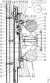
- the material web splice arrangement 1 illustrated in the figures comprises a first unwinding device 6 for unrolling a finite first material web 4 from a first material roll 5 and a second unwinding device 9 for unrolling a finite second material web 7 from a second material roll 8.
- the finite first material web 4 and the finite second material web 7 are firmly connected to one another by means of the material web splice arrangement 1 to provide the endless material web 3.
- the material web splice arrangement 1 has a base frame 10 with a base frame base 11, a base frame stand 12 and a base frame carrier 13.
- the base frame base 11 is attached to a floor or base (not shown).
- the base frame stand 12 is attached at the top of the base frame base 11.
- the base frame stand 12 extends vertically or perpendicularly to the floor.
- the base frame support 13 is arranged on an end region of the base frame stand 12 opposite the base frame base 11 and runs parallel or horizontally to the floor.
- the roll-off devices 6, 9 are pivotably mounted on the base frame base 11 and are arranged opposite one another relative to the base frame stand 12.
- the first unwinding device 6 has a first receiving part (not shown) for receiving the first roll of material 5, which is guided into a central opening of the first roll of material 5 and is mounted around a horizontal first axis of rotation between two parallel first holding arms 14 of the first unwinding device 6 .
- the second unwinding device 9 is designed corresponding to the first unwinding device 6. It has a second receiving part (not shown) for receiving the second roll of material 8, which is guided into a central opening of the second roll of material 8 and is mounted around a horizontal second axis of rotation between two parallel second holding arms 15 of the second unwinding device 9. The axes of rotation of the receiving parts run parallel to one another.
- the finite first material web 4 is according to Fig. 1 is fed via a first feed roller 16 to a cutting and connecting device 17 of the material web splicing arrangement 1, while the finite second material web 7 according to FIG Fig. 1 is guided via a second feed roller 18 into the material web splicing arrangement 1 in preparation for a splicing process.
- Each feed roller 16, 18 is rotatably mounted on the base frame support 13. They have horizontal axes of rotation that run parallel to one another.
- the feed rollers 16, 18 are rotatably arranged on feed roller support arms which are pivotably mounted on the base frame support 13.
- the cutting and connecting device 17 is used to produce the endless material web 3 from the finite material webs 4, 7. It comprises a first preparation device 19 and a second preparation device 20, a first connecting device 21, a second connecting device 22, a table device 23 and a guide 24.
- the first preparation device 19 is located according to FIG Fig. 1 momentarily above the first roll of material 5 on the base frame support 13, while the second preparation device 20 according to FIG Fig. 1 is currently in the area of the second roll of material 8 above the same on the base frame support 13.
- the guide 24 extends straight into / on the base frame support 13 and parallel to the floor.
- the table device 23 is arranged between the preparation devices 19, 20.
- the preparation devices 19, 20 and the table device 23 can be displaced along the guide 24 and relative to the connecting devices 21, 22, which are arranged along the guide 24 at a distance from one another on the base frame support 13 above the guide 24.
- a first vacuum roller 25 and a second vacuum roller 26 are displaceably guided along the guide 24.
- the first vacuum roller 25 is arranged opposite the table device 23 relative to the first preparation device 19 and can be placed under vacuum.
- the first preparation device 19 is thus arranged between the first vacuum roller 25 and the table device 23.
- the second vacuum roller 26 is arranged opposite the table device 23 relative to the second preparation device 20 and can be placed under vacuum.
- the second preparation device 20 is thus arranged between the second vacuum roller 26 and the table device 23.
- the preparation devices 19, 20 are constructed identically and are arranged essentially symmetrically with respect to a vertically running plane of symmetry.
- the first preparation device 19 has a rotatably mounted first transport or holding roller 27 for feeding the finite first material web 4.
- the first transport roller 27 of the first preparation device 19 is provided with an adhesive layer, for example, for holding and feeding the finite first material web 4 and can be displaced along the guide 24 for transporting the finite first material web 4 to the first or second connecting device 21, 22.
- the first transport roller 27 can be configured without an adhesive layer.
- the second preparation device 20 has a rotatably mounted second transport or holding roller 28 for feeding the finite second material web 7.
- the second transport roller 28 of the second preparation device 20 is provided, for example, with an adhesive layer for holding and feeding the finite second material web 7 and can be displaced along the guide 24 for transporting the finite second material web 7 to the first or second connecting device 21, 22.
- a configuration of the second transport roller 28 without an adhesive layer is possible.
- Each preparation device 19, 20 has its own first and second displacement drive 29, 30 for its displacement along the guide 24.
- the connecting devices 21, 22 are of identical design and are arranged symmetrically on the base frame support 13 with respect to a vertically running plane of symmetry.
- the first connecting device 21 comprises a first cutting unit 31 with an actuatable first cutting knife 32 for cutting the finite first material web 4 before connecting it to the finite second material web 7 and a first pressure roller 33 for connecting the finite material webs 4, 7 to form the endless material web 3.
- the first cutting unit 31 of the first connecting device 21 and the first pressure roller 33 are fastened directly adjacent to the guide 24 to the base frame support 13 in such a way that the transport rollers 27, 28 of the preparation devices 19, 20 and the table device 23 along the guide 24 to the Connecting devices 21, 22 can be guided past.
- the second connecting device 22 comprises a second cutting unit 34 with an actuatable second cutting knife 35 for cutting the finite second material web 7 before connecting it to the finite first material web 4 and a second pressure roller 36 for connecting the finite material webs 4, 7 to form the endless material web 3.
- the second cutting unit 34 of the second connecting device 22 and the second pressure roller 36 are fastened directly adjacent to the guide 24 to the base frame support 13 in such a way that the transport rollers 27, 28 of the preparation devices 19, 20 and the table device 23 along the guide 24 to the Connecting devices 21, 22 can be guided past.
- the vacuum rollers 25, 26, the feed rollers 16, 18 and the transport rollers 27, 28 and the pressure rollers 33, 36 extend parallel to one another and horizontally. They also extend parallel to the rolls of material 5, 8.
- the table device 23 interacts with the first preparation device 19, the second preparation device 20, the first connecting device 21 or the second connecting device 22 and can be moved along the guide 24, in particular also independently of these.
- the cutting and connecting device 17 is followed by a threading assistance arrangement 38 in the transport direction 37 of the endless material web 3 or finite first material web 4, which is arranged essentially above the second material roll 8 and above the guide 24 on the base frame support 13.
- the threading assistance arrangement 38 comprises a first conveyor roller 39 and a second conveyor roller 40, which are identical and are only arranged parallel to one another. They extend like the vacuum rollers 25, 26, feed rollers 16, 18, transport rollers 27, 28 and the pressure rollers 33, 36 perpendicular to the transport direction 37 of the endless material web 3 or the finite material web 4, 7.
- the conveyor rollers 39, 40 are in the base frame support 13 and together form a conveyor gap through which the endless material web 3 or finite first material web 4 runs.
- the threading assistance arrangement 38 further comprises two conveyor roller drives which are in drive connection with a conveyor roller 39 and 40, respectively.
- the conveyor rollers 39, 40 are coupled to one another via a gear mechanism and can be driven in rotation in opposite directions.
- the threading assistance arrangement 38 is able to support the introduction of the finite first or second material web 4, 7 into the material web splice arrangement 1. With such a In the threading process, the conveyor rollers 39, 40 are driven in rotation for the corresponding threading of the respective finite material web 4, 7.
- a first deflection roller 41 is arranged, which is rotatably mounted on a storage carriage 42 and is assigned to the endless material web 3 or finite first material web 4 for deflecting the same.
- the storage trolley 42 is arranged in the region of an upper end of the base frame support 13 facing away from the base frame support 13 and can be displaced along a storage trolley guide 43 which extends parallel to the floor and above the guide 24 in the base frame support 13.
- the storage trolley guide 43 provides a displacement path for the storage trolley 42 and extends essentially along the entire base frame carrier 13.
- the storage trolley 42 can be displaced in opposite directions of displacement between a first end position and a second end position. In the first end position, the storage carriage 42 is arranged adjacent to a material web outlet or exit 44, while in the second end position the storage carriage 42 is located at a distance or at a distance from the material web outlet 44. In Fig. 1 the storage carriage 42 is arranged adjacent to the material web outlet 44.
- a second deflecting roller 45 is rotatably mounted on the base frame support 13 in the region of the material web outlet 44 above the storage carriage guide 43.
- the second deflecting roller 45 is arranged downstream of the first deflecting roller 41 in relation to the transport direction 37.
- the second deflecting roller 45 is followed by a third deflecting roller 46 in relation to the transport direction 37 for deflecting the endless material web 3 or the finite first material web 4, which is rotatably mounted on the storage carriage 42 and is arranged adjacent to the first deflecting roller 41.
- a fourth deflection roller 47 is rotatably mounted on the base frame support 13 at the level of the storage carriage guide 43 in the area of the material web outlet 44.
- the fourth deflection roller 47 is arranged downstream of the third deflection roller 46 in relation to the transport direction 37.
- the fourth deflection roller 47 is followed by a fifth deflection roller 48, which is mounted on the storage carriage 42, in relation to the transport direction 37 for deflecting the endless material web 3 or the finite first material web 4.
- the third deflecting roller 46 is arranged between the first deflecting roller 41 and the fifth deflecting roller 48.
- the axes of rotation of the guide rollers 41, 45, 46, 47, 48 run parallel to each other and lie in a common horizontal plane. They extend perpendicular to the transport direction 37.
- the storage carriage 42 can be displaced along the storage carriage guide 43 due to a change in the web tension of the endless material web 3.
- the storage trolley 42 can be displaced by a storage trolley adjusting drive.
- the material web splice arrangement 1 has a material web draw-in link guide 49 for guiding the finite first material web 4, the finite second material web 7 or the endless material web 3 during a draw-in process.
- the link guide 49 extends from a material web inlet of the material web splice arrangement 1 or from the first material roll 5 and the second material roll 8 without interruption or essentially as far as the material web outlet 44 or beyond it. Alternatively, this then has, for example, at least one interruption between the material web inlet, the first material roll 5 or the second material roll 8 and the material web outlet 44.
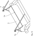
- the link guide 49 has a first guide device 50 on the input side, which is fixedly arranged on the base frame support 13 and is assigned to the first holding arm 14 or the first roll of material 5.
- the input-side first guide device 50 comprises an input-side straight or essentially straight first guide device 51 and an input-side essentially straight second guide device 52.
- the input-side first guide device 51 and the input-side second guide device 52 run essentially obliquely to one another. They are immobile to one another.
- the first guide device 51 on the input side has, adjacent to the first roll of material 5, a free first infeed input 53 which faces away from the base frame support 13.
- the second guide device 52 on the input side has, adjacent to the first roll of material 5, a free second intake input 54 which faces away from the base frame carrier 13 and is arranged at a distance from the first intake inlet 53.
- the first draw-in inlet 53 and the second draw-in inlet 54 are arranged in the circumferential direction around the first roll of material 5 adjacent to the first roll of material 5 during a draw-in process.
- the input-side first guide device 51 and the input-side second guide device 52 run towards one another from their respective draw-in inlet 53 and 54 in the direction of the base frame support 13 and converge at a first junction 55 of the link guide 49.
- the input-side first guide device 50 is essentially V-shaped.
- the input-side first guide device 50 Downstream of the first merging point 55 in relation to a draw-in direction or the transport direction 37 of the material web 3, 4 to be drawn in, the input-side first guide device 50 has a common first output 56, which is arranged below the guide 24 and faces the guide 24 or vertically directed upwards. The first exit 56 is arranged adjacent to the first feed roller 16.
- the slotted guide 49 also includes a first curved guide device 57 which is arranged on the first preparation device 19 or on its carriage, the entrance 58 of which faces downward or faces the first roll of material 5.
- the first guide arch device 57 runs adjacent above or laterally adjacent above around the first transport roller 27 in an essentially semicircular arc shape and has a first reversal area 57a on the output side, which has an upwardly open first exit end 59 above the guide 24 or in an upper area thereof.
- a substantially straight first guide device 60 of the link guide 49 is arranged on the base frame support 13.
- the essentially straight first guide device 60 extends adjacent to the guide 24 and runs essentially from the level of the first feed roller support arm down to the first pressure roller 33. Upstream, the essentially straight first guide device 60 has a downwardly open first connection 61.
- a diagonally extending first guide device 62 of the link guide 49 adjoins the essentially straight first guide device 60 opposite the first connection 61.
- the inclined first guide device 62 extends from the first pressure roller 33 in the transport direction 37 obliquely upwards in the direction of the second pressure roller 36 and diagonally opposite the guide 24. It ends at the top adjacent to the second pressure roller 36.
- the link guide 49 also has a second guide device 63 on the input side, which is essentially identical to the first guide device 50 on the input side and is fixedly arranged on the base frame support 13.
- the second guide device 63 on the input side is assigned to the second support arm 15 or the second roll of material 8. It comprises an input-side essentially straight first guide device 64 and an input-side essentially straight second guide device 65.
- the input-side first guide device 64 and input-side second guide device 65 of the input-side second guide device 63 run essentially obliquely to one another. They are immobile to one another.
- the first guide device 64 on the input side has, adjacent to the second roll of material 8, a free first intake input 66 which faces away from the base frame support 13.
- the second guide device 65 on the input side has, adjacent to the second roll of material 8, a free second infeed inlet 67 which faces away from the base frame support 13 and is arranged at a distance from the first infeed inlet 66.
- the first feed inlet 66 and the second feed inlet 67 are arranged in the circumferential direction around the second roll of material 8 adjacent to the second roll of material 8 during a draw-in process.
- the first guide device 64 on the input side and the second guide device 65 on the input side run towards one another from their respective intake inlet 66 and 67 in the direction of the base frame support 13 and converge at a second junction 68 of the link guide 49.
- the input-side second guide device 63 is essentially V-shaped.
- the second guide device 63 on the input side has a common second output 69 arranged below the guide 24, which faces the guide 24 or vertically directed upwards.
- the second exit 69 is arranged adjacent to the second feed roller 18.
- the link guide 49 also comprises a second guide arch device 70, which is arranged on the second preparation device 20 or on its carriage, the second entrance of which faces downward or faces the second roll of material 8.
- the second guide arch device 70 runs around the second transport roller 28 in an essentially semicircular arc shape and has a second reversal region 71 on the output side, which has an upwardly open second exit end 72 above the guide 24 or in an upper region thereof.
- the second curved guide device 70 is designed symmetrically to the first curved guide device 57 with respect to a vertical plane of symmetry.
- a substantially straight second guide device 73 of the link guide 49 is arranged above the guide 24 on the base frame support 13.
- the essentially straight second guide device 73 extends adjacent to the guide 24 and runs essentially from the height of the second feed roller support arm down to the bottom of the second pressure roller 36. Upstream, the essentially straight second guide device 73 has a downwardly open second connection 74.
- a substantially semicircular arc-shaped second guide device 75 of the link guide 49 adjoins the essentially straight second guide device 73 opposite the second connection 74.
- the essentially semicircular second guide device 73 extends adjacent or laterally adjacent to the second pressure roller 36 on the side facing the first pressure roller 33.
- the inclined first guide device 62 and the essentially semicircular second guide device 75 converge and unite at a third merging point 76 at the top adjacent or laterally to the second pressure roller 36.
- a guide device 77 on the output side adjoins the third junction 76 downstream, which runs straight to the threading assistance arrangement 38 and extends from above adjacent or laterally adjacent to a conveyor gap formed between the conveyor rollers 39, 40.
- the output-side guide device 77 extends there adjacent or laterally adjacent to the conveyor rollers 39, 40. It extends essentially in the shape of a quarter of a circle around the first conveyor roller 39 or laterally adjacent to it and essentially in a semicircular arc around the second conveyor roller 40 or laterally adjacent to it this.
- the output-side guide device 77 also extends adjacent or laterally adjacent around the first deflection roller 41 on the storage carriage 42.
- the output-side guide device 77 also extends adjacent or laterally adjacent essentially in the shape of a semicircle around the stationary second deflecting roller 45.
- the output-side guide device 77 extends adjacent or laterally adjacent in the shape of a part of a circle around the third deflecting roller 46 on the storage carriage 42.
- the guide device 77 on the output side extends essentially in the shape of a three-quarter circular arc adjacent or laterally adjacent around the stationary fourth deflecting roller 47.
- the guide device 77 on the output side extends essentially adjacent to or laterally adjacent in the shape of three quarters of a circle around the fifth deflecting roller 48 on the storage carriage 42.
- the guide device 77 on the output side runs out of the material web splicing arrangement 1 via the material web outlet 44.
- Each guide device 51, 52, 57, 60, 62, 64, 65, 70, 73, 75, 77 comprises opposite guide elements arranged in pairs, which are correspondingly identically shaped and rail-like or link-like.
- the guide elements are each arranged laterally adjacent or laterally outside of the material web 3, 4, 7 to be drawn in. They are preferably arranged in the transverse direction of the material web 3, 4, 7 at a distance from the material web 3, 4, 7 to be drawn in or its longitudinal edge.
- the guide elements are open towards the material web 3, 4, 7 to be drawn in and are, for example, U-shaped in cross section.
- the material web splice arrangement 1 comprises at least one material web clamping device 78 for holding the material web 3, 4, 7 to be drawn in by clamping ( Figs. 11-14 ).
- the material web clamping device 78 has a profile-like rigid cross member 79 which extends in the transverse direction of the material web 3, 4, 7 to be drawn in and protrudes laterally in the transverse direction of the material web 3, 4, 7 to be drawn in.
- the cross member 79 engages in opposing guide elements and is thus guided displaceably perpendicular to its extent.
- the cross member 79 can be displaced along the link guide 49 and is thus capable, depending on its position, of translatory and / or arcuate movements or the like execute. It extends vertically between the opposing guide elements.
- the cross member 79 has a material web receiving opening 80 which is open opposite to the feed direction or transport direction 37. It is essentially U-shaped.
- the cross member 79 has a base 81 opposite the material web receiving opening 80 and a holding web 82 projecting from the base 81 as well as an outer web 83 projecting from the base 81.
- the retaining web 82 and outer web 83 run parallel and spaced apart from one another.
- the holding web 82 cooperates with the material web 3, 4, 7 to be drawn in, while the outer web 83 is arranged at a distance from it.
- the cross member 79 supports a clamping bar 84 which is arranged between the holding web 82 and the outer web 83 and is pivotable with respect to these.
- the clamping bar 84 starting from the base 81, preferably protrudes with respect to the holding web 82 and the outer web 83.
- An activation device 85 which is an electrical pulse receiver, is preferably arranged on each of the opposing guide elements adjacent to the first and second feed inlet 53 and 54 of the first guide device 50 on the input side and adjacent to the first and second feed inlet 66 and 67 of the second guide device 63 on the input side 86 includes.
- the activation device 85 is assigned to the clamping bar 84.
- the pulse receiver 86 is connected to the clamping bar 84 and is able to pivot it.
- Two coupling chains 87 are arranged on the base 81 opposite the clamping bar 84.
- the coupling chains 87 run in the opposing guide elements of the guide devices 51, 52, 57, 60, 62, 64, 65, 70, 73, 75, 77 and can be displaced by a motor.
- the link guide 49, the material web clamping device 78 and the coupling chains 87 including their displacement drive (s) are part of a material web pull-in device.
- the operation of the material web splice arrangement 1 is described below by way of example. This is done by Fig. 1 went out. At Fig. 1 the finite first material web 4 is unrolled from the first roll of material 5 and thus conveyed. It was drawn into the material web splice arrangement 1 by means of the material web pull-in device with the finite first material web 4 being unrolled from the first material roll 5, which will be described in detail below.
- the finite first material web 4 is guided over the first feed roller 16, where the finite first material web 4 is deflected, to the cutting connection device 17. It is passed between the pressure rollers 33, 36, which are spaced apart from one another, and rests against these circumferentially in some areas.
- the finite first material web 4 or the endless material web 3 Downstream of the cutting and connecting device 17, the finite first material web 4 or the endless material web 3 is introduced from above into the threading assistant assembly 38 and wraps around its two conveyor rollers 39, 40, resting against the conveyor rollers 39, 40.
- the threading assistance arrangement 38 favorably supports the transport of the finite first material web 4 or the endless material web 3 and is driven accordingly.
- the finite first material web 4 or the endless material web 3 is then guided around the first deflection roller 41 on the storage carriage 42. Subsequently, the finite first material web 4 or the endless material web 3 is guided around the stationary second deflecting roller 45. Subsequently, the finite first material web 4 or the endless material web 3 is guided around the third deflection roller 46 on the storage carriage 42. Subsequently, the finite first material web 4 or the endless material web 3 is guided around the stationary fourth deflecting roller 47. Subsequently, the finite first material web 4 or the endless material web 3 is guided around the fifth deflection roller 48 on the storage carriage 42. The finite first material web 4 or the endless material web 3 then leaves the material web splice arrangement 1 via the material web outlet 44.
- the finite first material web 4 or the endless material web 3 extends largely adjacent to the link guide 49.
- the storage trolley 42 is arranged adjacent to the material web outlet 44.
- the first vacuum roller 25 is arranged at a distance from the first transport roller 27.
- the table device 23 is located adjacent to the connecting devices 21, 22. It is arranged at a distance from the preparation devices 19, 20.
- the cutting and connecting device 17 is in its inactive state. In this state, the finite first material web 4 or the endless material web 3 merely passed through the cutting and connecting device 17.
- the finite second material web 7 was drawn into the material web splice arrangement 1 by means of the material web pull-in device with the finite second material web 7 being unrolled from the second material roll 8.
- the material web splice arrangement 1 has received the second material roll 8 and also the first material roll 5 after alignment in their circumferential direction in an exactly defined starting position by means of the material roll preparation arrangement 2.
- the clamping bar 84 To pull in the finite second material web 7, the clamping bar 84 is in its clamping position and is pivoted in the direction of the material web holding web 82 with the finite second material web 7 being clamped.
- the finite second material web 7 to be drawn in is thus arranged between the retaining web 82 and the clamping bar 84 and held in a clamping manner. It passes through the material web receiving opening 80.
- the coupling chains 87 are drawn in synchronously by a motor, so that the cross member 79 together with the fixed, finite second material web 7 is drawn along the link guide 49 as far as the second preparation device 20.
- the cross member 79 is pulled around the transport roller 28 so that it faces the second vacuum roller 26. Due to the unwinding direction of the second roll of material 8, the finite second material web 7 enters the link guide 49 via the free second feed inlet 67.
- the second output 69 of the second guide device 63 on the input side and the second input of the second guide arch device 70 are arranged adjacent to one another, so that the finite second material web 7 is capable of moving from the input-side second guide device 63 into the second guide arch device 70 during the drawing-in process.
- the second exit end 72 of the second curved guide device 70 and the second connection 74 of the essentially straight, second guide device 73 are arranged adjacent to one another, so that the finite second material web 7 is capable of moving from the second curved guide device 70 into the essentially straight, second guide device 73 during the drawing-in process to get.
- the second preparation device 20 together with the second guide arch device 70 have been correspondingly displaced along the guide 24 for this purpose.
- the table device 23 then moves along the guide 24 to the second preparation device 20 for a splicing process. If the second preparation device 20 and the table device 23 are arranged adjacent to one another, the threaded, finite second material web 7 between the second preparation device 20 and the table device 23 held clamped. In particular, the finite second material web 7 is held between the second transport roller 28 and a holding element 88 of the table device 23 while deforming the same. The table device 23 and the second preparation device 20 assume a holding position.
- the table device 23 then moves along the guide 24 to the second preparation device 20.
- the table device 23 and the second preparation device 20 together with the second guide arch device 70 move together along the guide 24 in the direction of the second vacuum roller 26, which in turn moves in the direction of the second preparation device 20 moves.
- the second transport roller 28 and the second vacuum roller 26 are arranged adjacent to each other, the second The output 69 of the input-side second guide device 63 and the second input of the second guide arch device 70 are arranged separated from one another or at a distance from one another.
- the second exit end 72 of the second curved guide device 70 and the second connection 74 of the essentially straight second guide device 73 are arranged separated from one another or at a distance from one another ( Fig. 3 ).
- the second transport roller 28 and the second vacuum roller 26 are then driven in opposite directions in rotation in such a way that the finite second material web 7 is conveyed back against its actual feed direction and a double-sided adhesive splice 89 arranged at the end of the finite second material web 7 between one by the second transport roller 28 and the second vacuum roller 26 is formed gap.
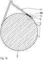
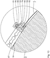
- the splice piece 89 is adhesively connected to the finite second material web 7 with an inner adhesive surface.
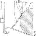
- the splice piece 89 faces the second vacuum roller 26 with its detachable, non-adhesive separating cover 90 and rests against the latter with the separating cover 90.
- the second vacuum roller 26 is active and thus sucks the separating cover 90 of the splice piece 89 through the vacuum it generates and removes it from the actual splice piece 89, exposing an outer adhesive surface of the splice piece 89 opposite the inner adhesive surface.
- the second transport roller 28 and second vacuum roller 26 are part of a divider cover removal device.
- the second preparation device 20 and the table device 23 then travel in the coupled state along the guide 24 in the direction of the first preparation device 19 or to the first connecting device 21, the finite second material web 7 clamping between the Table device 23 and the second transport roller 28 is held.
- the second preparation device 20 and the table device 23 move away from the second vacuum roller 26 ( Fig. 5 ).
- the second transport roller 28 is blocked in its rotation.
- the rotation of the second transport roller 28 is then released again.
- the second transport roller 28 is pivoted in such a way that the splice piece 89 reaches an upwardly facing splice position.
- the second transport roller 28 is moved under the first connecting device 21, so that the splice piece 89 faces the first connecting device 21.
- the endless material web 3 or finite first material web 4 is pressed against the adhesive splice piece 89, which faces the first pressure roller 33, by shifting the first pressure roller 33 of the first connecting device 21. This results in an adhesive connection of the endless material web 3 or finite first material web 4 to the finite second material web 7.
- the supply of the finite first material web 4 to the endless material web 3 is stopped.
- the finite first material web 4 is separated from the endless material web 3 by means of the first cutting knife 32.
- the finite second material web 7 is now unrolled from the second material roll 8.
- the first roll of material 5 is now prepared analogously to the previous description for its later unrolling.
- the drawing of the finite first material web 4 into the material web splice arrangement 1 takes place essentially analogously to the material web drawing-in device.
- Fig. 9 shows, for a splicing process essentially analogous to the previous description, a splice piece 89 arranged on the finite first material web 4 is adhesively connected to the endless material web 3 or finite second material web 7, so that the finite first material web 4 is adhered to the endless material web 3 connected is. The supply of the finite second material web 7 is now stopped.
- the first output 56 of the first guide device 50 on the input side and the first input 58 of the first curved guide device 57 are arranged adjacent to one another so that the finite first material web 4 is able to pass from the first guide device 50 on the input side into the first curved guide device 57 during the drawing-in process.
- the first exit end 59 of the first curved guide device 57 and the first connection 61 of the essentially straight first guide device 60 are arranged adjacent to one another, so that the finite first material web 7 is able to move from the first curved guide device 57 into the essentially straight first guide device 60 during the drawing-in process to get.
- the first preparation device 20 together with the first guide arch device 57 have been displaced accordingly along the guide 24 for this purpose.
- the new, finite material web 4 or 7 is only fed via the material web feed device as described up to the respective transport roller 27 or 28 led.
- the respective finite material web 4 or 7 is completely inserted into the material web splice arrangement 1 up to its material web outlet 44 or into an adjacent production arrangement or by means of the material web pull-in device . -device retractable.
- the first output 56 of the first guide device 50 on the input side and the first input 58 of the first curved guide device 57 are then arranged adjacent to one another, so that the finite first material web 4 is able to pass from the first guide device 50 on the input side into the first curved guide device 57 during the drawing-in process.
- the first exit end 59 of the first curved guide device 57 and the first connection 61 of the essentially straight first guide device 60 are arranged adjacent to one another, so that the finite first material web 7 is able to move from the first curved guide device 57 into the essentially straight first guide device 60 during the drawing-in process to get.
- the first preparation device 20 together with the first guide arch device 57 have been displaced accordingly along the guide 24 for this purpose.
- the second output 69 of the input-side second guide device 63 and the second input of the second guide arch device 70 are arranged adjacent to one another, so that the finite second material web 7 at is able to move from the input-side second guide device 63 into the second guide arch device 70 during the drawing-in process.
- the second exit end 72 of the second curved guide device 70 and the second connection 74 of the essentially straight, second guide device 73 are arranged adjacent to one another, so that the finite second material web 7 is capable of moving from the second curved guide device 70 into the essentially straight, second guide device 73 during the drawing-in process to get.
- the second preparation device 20 together with the second guide arch device 70 have been correspondingly displaced along the guide 24 for this purpose.
- the coupling chains 87 are drawn in synchronously by a motor, so that the cross member 79 together with the fixed, finite second material web 7 is drawn along the link guide 49 up to the material web outlet 44 or beyond it.
- the material web clamping device 78 is preferably automatically or motorized shifted into its starting position for receiving the respective finite material web 4 or 7.
- the holding web 82 engages under the respective finite material web 4 or 7.
- a free, pick-up section of the respective finite material web 4 or 7 is spaced from the material web sections of the respective material roll 5 or 8 arranged below arranged.
- the material web 4, 7 penetrates the material web receiving opening 80.
- the material web detection element delivers a corresponding electrical trigger signal which preferably motor-driven displacement of the clamping bar 84 into its clamping position.
- the correct position of the cross member 79 in relation to the finite material web 4, 7 or its end is preferably achievable since the material web splice arrangement 1 receives the material roll 5, 8 in an aligned or precisely defined starting position and thus already knows where it is The end of the respective material web 4, 7 is located on the material roll 5, 8.
- the cross member 79 is then displaced by means of the coupling chains 87 into its desired position while the respective finite material web 4 or 7 is drawn in.
- a fully automated recording of the roll of material 5, 8 is possible.
- control or actuation of the individual units is preferably carried out by at least one corresponding electrical or electronic actuation or control unit.
- the endless material web 3 is fed together with another endless material web to a corrugated cardboard production device for the production of a one-sided laminated corrugated cardboard web.
- a corrugating device with rollers for producing a corrugated sheet with a corrugation from one of the endless sheets of material.
- the corrugated cardboard production device has a glue application device which applies glue to tips of the corrugation of the corrugated sheet.
- the corrugated cardboard production device has a pressing module for pressing the smooth web against the corrugated web provided with glue, the one-sided laminated Corrugated cardboard sheet is created from the corrugated sheet and smooth sheet. A reverse use of the material webs is alternatively possible.
- the material web holding device is not designed here as a material web clamping device 78, but rather as a material web suction device 78a.
- the material web suction device 78a has a cross member 79a which essentially encloses an interior space and is designed, for example, as a rectangular profile body. Opposing flow openings 91 are formed in the cross member 79a.
- the cross member 79a is in flow connection with a suction source 92.
- the suction source 92 In the active state of the suction source 92, the material web 4, 7 to be drawn in is sucked onto the cross member 79a and rests firmly against it in the area of the flow openings 91 adjacent to the material web 4, 7 to be drawn in.
- the function of the material web suction device 78a or the corresponding material web pull-in device is essentially analogous to that of the material web clamping device 78.
- upstream “upstream”, “downstream”, “input side”, “output side” or the like used here relate in particular to a conveying direction of an associated material web.
Landscapes
- Replacement Of Web Rolls (AREA)
- Laminated Bodies (AREA)
- Adhesive Tapes (AREA)
Applications Claiming Priority (2)
| Application Number | Priority Date | Filing Date | Title |
|---|---|---|---|
| DE102019201592 | 2019-02-07 | ||
| DE102019203746.1A DE102019203746A1 (de) | 2019-02-07 | 2019-03-19 | Klebestück |
Publications (3)
| Publication Number | Publication Date |
|---|---|
| EP3693302A2 true EP3693302A2 (fr) | 2020-08-12 |
| EP3693302A3 EP3693302A3 (fr) | 2020-11-04 |
| EP3693302B1 EP3693302B1 (fr) | 2023-03-08 |
Family
ID=69375297
Family Applications (1)
| Application Number | Title | Priority Date | Filing Date |
|---|---|---|---|
| EP20154231.3A Active EP3693302B1 (fr) | 2019-02-07 | 2020-01-29 | Pièce adhésive |
Country Status (1)
| Country | Link |
|---|---|
| EP (1) | EP3693302B1 (fr) |
Family Cites Families (6)
| Publication number | Priority date | Publication date | Assignee | Title |
|---|---|---|---|---|
| JPS63165258A (ja) * | 1986-12-25 | 1988-07-08 | Tokyo Jido Kikai Seisakusho:Kk | 帯状材の自動接続装置 |
| USRE38356E1 (en) * | 1994-04-26 | 2003-12-23 | 3M Innovative Properties Company | Splicing method and splice using the splicing tape |
| JP3406426B2 (ja) * | 1995-07-28 | 2003-05-12 | 日本たばこ産業株式会社 | 粘着テープ供給装置 |
| TW450936B (en) * | 1998-09-03 | 2001-08-21 | Japan Tobacco Inc | Adhering device for adhesive sheet |
| US6899933B2 (en) * | 2002-09-09 | 2005-05-31 | Permacel | Splicing tape with separating portions |
| PL2433994T3 (pl) * | 2010-09-27 | 2014-05-30 | Illinois Tool Works | Taśma klejąca i sposób wytwarzania taśmy klejącej |
-
2020
- 2020-01-29 EP EP20154231.3A patent/EP3693302B1/fr active Active
Also Published As
| Publication number | Publication date |
|---|---|
| EP3693302A3 (fr) | 2020-11-04 |
| EP3693302B1 (fr) | 2023-03-08 |
Similar Documents
| Publication | Publication Date | Title |
|---|---|---|
| EP3693305B1 (fr) | Dispositif de retrait de protecteur | |
| DE19540689C2 (de) | Schneideeinrichtung | |
| DE2920329C2 (de) | Vorrichtung zum einziehen einer warenbahn in einen schwebetrockner | |
| CH656861A5 (de) | Vorrichtung zum lagern von papierbogen. | |
| DE202007003696U1 (de) | Bandaufbringvorrichtung | |
| DE3914776C2 (de) | Verfahren und Vorrichtung zum Aufwickeln und Querschneiden einer laufenden Warenbahn | |
| EP3693302B1 (fr) | Pièce adhésive | |
| DE10058458B4 (de) | Vorrichtung zum Verbinden zweier Materialbahnen | |
| DE3703845A1 (de) | Vorrichtung zum vereinzeln gestapelter zuschnitte | |
| EP3915910B1 (fr) | Agencement de traitement /d'usinage des bandes de matière | |
| EP0887295A2 (fr) | Dispositif pour sectionner une bande de papier | |
| DE10112636B4 (de) | Verfahren und Vorrichtung zur Klebestellenvorbereitung einer Materialrolle | |
| DE2455913B2 (de) | Kopswechselvorrichtung | |
| EP0046262B2 (fr) | Dispositif de fabrication de produits, qui sont pliés transversalement au moins une fois et qui sont coupés parallèlement au pli transversal | |
| DE2248569C3 (de) | Vorrichtung zum Verbinden einer von einer Wickelrolle ablaufenden Bahn mit einer neuen Bahn | |
| DE2747099B2 (de) | Vorrichtung zum Wickeln eines Filmwickels | |
| DE202013102342U1 (de) | Spleißeinrichtung zum Spleißen von Cordmaterial | |
| EP1529011A2 (fr) | Procede, systeme et dispositif pour preparer un rouleau de bobinage en vue d'un remplacement automatique, pour saisir une bande de produit et pour amener une bande adhesive double face sur une surface | |
| DE4116194B4 (de) | Vorrichtung zum Verbinden von Kettbahnen beim Zettelbaumpartiewechsel | |
| DE10058437B4 (de) | Vorrichtungen zum Verbinden zweier Materialbahnen | |
| DE102004063900A1 (de) | Klebespendeeinrichtungen mit einer Vorratsrolle | |
| DE10040107A1 (de) | Hülsenabziehvorrichtung | |
| DE102004021623A1 (de) | Vorrichtungen zum Vorbereiten einer Vorratsrolle für einen fliegenden Rollenwechsel und eine Klebebandspendeeinrichtung | |
| DE10058436B4 (de) | Vorrichtungen zum Verbinden zweier Materialbahnen | |
| DE202005021272U1 (de) | Vorrichtungen zum Vorbereiten einer aus einer Materialbahn gewickelten Vorratsrolle für einen fliegenden Rollenwechsel |
Legal Events
| Date | Code | Title | Description |
|---|---|---|---|
| PUAI | Public reference made under article 153(3) epc to a published international application that has entered the european phase |
Free format text: ORIGINAL CODE: 0009012 |
|
| STAA | Information on the status of an ep patent application or granted ep patent |
Free format text: STATUS: THE APPLICATION HAS BEEN PUBLISHED |
|
| AK | Designated contracting states |
Kind code of ref document: A2 Designated state(s): AL AT BE BG CH CY CZ DE DK EE ES FI FR GB GR HR HU IE IS IT LI LT LU LV MC MK MT NL NO PL PT RO RS SE SI SK SM TR |
|
| AX | Request for extension of the european patent |
Extension state: BA ME |
|
| RIC1 | Information provided on ipc code assigned before grant |
Ipc: B65H 19/10 20060101AFI20200817BHEP |
|
| PUAL | Search report despatched |
Free format text: ORIGINAL CODE: 0009013 |
|
| AK | Designated contracting states |
Kind code of ref document: A3 Designated state(s): AL AT BE BG CH CY CZ DE DK EE ES FI FR GB GR HR HU IE IS IT LI LT LU LV MC MK MT NL NO PL PT RO RS SE SI SK SM TR |
|
| AX | Request for extension of the european patent |
Extension state: BA ME |
|
| RIC1 | Information provided on ipc code assigned before grant |
Ipc: B65H 19/18 20060101ALI20200928BHEP Ipc: B65H 19/10 20060101AFI20200928BHEP |
|
| STAA | Information on the status of an ep patent application or granted ep patent |
Free format text: STATUS: REQUEST FOR EXAMINATION WAS MADE |
|
| 17P | Request for examination filed |
Effective date: 20210423 |
|
| RBV | Designated contracting states (corrected) |
Designated state(s): AL AT BE BG CH CY CZ DE DK EE ES FI FR GB GR HR HU IE IS IT LI LT LU LV MC MK MT NL NO PL PT RO RS SE SI SK SM TR |
|
| STAA | Information on the status of an ep patent application or granted ep patent |
Free format text: STATUS: EXAMINATION IS IN PROGRESS |
|
| 17Q | First examination report despatched |
Effective date: 20211103 |
|
| GRAP | Despatch of communication of intention to grant a patent |
Free format text: ORIGINAL CODE: EPIDOSNIGR1 |
|
| STAA | Information on the status of an ep patent application or granted ep patent |
Free format text: STATUS: GRANT OF PATENT IS INTENDED |
|
| INTG | Intention to grant announced |
Effective date: 20220920 |
|
| GRAS | Grant fee paid |
Free format text: ORIGINAL CODE: EPIDOSNIGR3 |
|
| GRAA | (expected) grant |
Free format text: ORIGINAL CODE: 0009210 |
|
| STAA | Information on the status of an ep patent application or granted ep patent |
Free format text: STATUS: THE PATENT HAS BEEN GRANTED |
|
| AK | Designated contracting states |
Kind code of ref document: B1 Designated state(s): AL AT BE BG CH CY CZ DE DK EE ES FI FR GB GR HR HU IE IS IT LI LT LU LV MC MK MT NL NO PL PT RO RS SE SI SK SM TR |
|
| REG | Reference to a national code |
Ref country code: CH Ref legal event code: EP Ref country code: AT Ref legal event code: REF Ref document number: 1552467 Country of ref document: AT Kind code of ref document: T Effective date: 20230315 |
|
| REG | Reference to a national code |
Ref country code: DE Ref legal event code: R096 Ref document number: 502020002657 Country of ref document: DE |
|
| REG | Reference to a national code |
Ref country code: IE Ref legal event code: FG4D Free format text: LANGUAGE OF EP DOCUMENT: GERMAN |
|
| REG | Reference to a national code |
Ref country code: ES Ref legal event code: FG2A Ref document number: 2943005 Country of ref document: ES Kind code of ref document: T3 Effective date: 20230608 |
|
| REG | Reference to a national code |
Ref country code: LT Ref legal event code: MG9D |
|
| P01 | Opt-out of the competence of the unified patent court (upc) registered |
Effective date: 20230527 |
|
| REG | Reference to a national code |
Ref country code: NL Ref legal event code: MP Effective date: 20230308 |
|
| PG25 | Lapsed in a contracting state [announced via postgrant information from national office to epo] |
Ref country code: RS Free format text: LAPSE BECAUSE OF FAILURE TO SUBMIT A TRANSLATION OF THE DESCRIPTION OR TO PAY THE FEE WITHIN THE PRESCRIBED TIME-LIMIT Effective date: 20230308 Ref country code: NO Free format text: LAPSE BECAUSE OF FAILURE TO SUBMIT A TRANSLATION OF THE DESCRIPTION OR TO PAY THE FEE WITHIN THE PRESCRIBED TIME-LIMIT Effective date: 20230608 Ref country code: LV Free format text: LAPSE BECAUSE OF FAILURE TO SUBMIT A TRANSLATION OF THE DESCRIPTION OR TO PAY THE FEE WITHIN THE PRESCRIBED TIME-LIMIT Effective date: 20230308 Ref country code: LT Free format text: LAPSE BECAUSE OF FAILURE TO SUBMIT A TRANSLATION OF THE DESCRIPTION OR TO PAY THE FEE WITHIN THE PRESCRIBED TIME-LIMIT Effective date: 20230308 Ref country code: HR Free format text: LAPSE BECAUSE OF FAILURE TO SUBMIT A TRANSLATION OF THE DESCRIPTION OR TO PAY THE FEE WITHIN THE PRESCRIBED TIME-LIMIT Effective date: 20230308 |
|
| PG25 | Lapsed in a contracting state [announced via postgrant information from national office to epo] |
Ref country code: SE Free format text: LAPSE BECAUSE OF FAILURE TO SUBMIT A TRANSLATION OF THE DESCRIPTION OR TO PAY THE FEE WITHIN THE PRESCRIBED TIME-LIMIT Effective date: 20230308 Ref country code: NL Free format text: LAPSE BECAUSE OF FAILURE TO SUBMIT A TRANSLATION OF THE DESCRIPTION OR TO PAY THE FEE WITHIN THE PRESCRIBED TIME-LIMIT Effective date: 20230308 Ref country code: GR Free format text: LAPSE BECAUSE OF FAILURE TO SUBMIT A TRANSLATION OF THE DESCRIPTION OR TO PAY THE FEE WITHIN THE PRESCRIBED TIME-LIMIT Effective date: 20230609 Ref country code: FI Free format text: LAPSE BECAUSE OF FAILURE TO SUBMIT A TRANSLATION OF THE DESCRIPTION OR TO PAY THE FEE WITHIN THE PRESCRIBED TIME-LIMIT Effective date: 20230308 |
|
| PG25 | Lapsed in a contracting state [announced via postgrant information from national office to epo] |
Ref country code: SM Free format text: LAPSE BECAUSE OF FAILURE TO SUBMIT A TRANSLATION OF THE DESCRIPTION OR TO PAY THE FEE WITHIN THE PRESCRIBED TIME-LIMIT Effective date: 20230308 Ref country code: RO Free format text: LAPSE BECAUSE OF FAILURE TO SUBMIT A TRANSLATION OF THE DESCRIPTION OR TO PAY THE FEE WITHIN THE PRESCRIBED TIME-LIMIT Effective date: 20230308 Ref country code: PT Free format text: LAPSE BECAUSE OF FAILURE TO SUBMIT A TRANSLATION OF THE DESCRIPTION OR TO PAY THE FEE WITHIN THE PRESCRIBED TIME-LIMIT Effective date: 20230710 Ref country code: EE Free format text: LAPSE BECAUSE OF FAILURE TO SUBMIT A TRANSLATION OF THE DESCRIPTION OR TO PAY THE FEE WITHIN THE PRESCRIBED TIME-LIMIT Effective date: 20230308 Ref country code: CZ Free format text: LAPSE BECAUSE OF FAILURE TO SUBMIT A TRANSLATION OF THE DESCRIPTION OR TO PAY THE FEE WITHIN THE PRESCRIBED TIME-LIMIT Effective date: 20230308 |
|
| PG25 | Lapsed in a contracting state [announced via postgrant information from national office to epo] |
Ref country code: SK Free format text: LAPSE BECAUSE OF FAILURE TO SUBMIT A TRANSLATION OF THE DESCRIPTION OR TO PAY THE FEE WITHIN THE PRESCRIBED TIME-LIMIT Effective date: 20230308 Ref country code: PL Free format text: LAPSE BECAUSE OF FAILURE TO SUBMIT A TRANSLATION OF THE DESCRIPTION OR TO PAY THE FEE WITHIN THE PRESCRIBED TIME-LIMIT Effective date: 20230308 Ref country code: IS Free format text: LAPSE BECAUSE OF FAILURE TO SUBMIT A TRANSLATION OF THE DESCRIPTION OR TO PAY THE FEE WITHIN THE PRESCRIBED TIME-LIMIT Effective date: 20230708 |
|
| REG | Reference to a national code |
Ref country code: DE Ref legal event code: R097 Ref document number: 502020002657 Country of ref document: DE |
|
| PLBE | No opposition filed within time limit |
Free format text: ORIGINAL CODE: 0009261 |
|
| STAA | Information on the status of an ep patent application or granted ep patent |
Free format text: STATUS: NO OPPOSITION FILED WITHIN TIME LIMIT |
|
| PG25 | Lapsed in a contracting state [announced via postgrant information from national office to epo] |
Ref country code: SI Free format text: LAPSE BECAUSE OF FAILURE TO SUBMIT A TRANSLATION OF THE DESCRIPTION OR TO PAY THE FEE WITHIN THE PRESCRIBED TIME-LIMIT Effective date: 20230308 Ref country code: DK Free format text: LAPSE BECAUSE OF FAILURE TO SUBMIT A TRANSLATION OF THE DESCRIPTION OR TO PAY THE FEE WITHIN THE PRESCRIBED TIME-LIMIT Effective date: 20230308 |
|
| 26N | No opposition filed |
Effective date: 20231211 |
|
| PG25 | Lapsed in a contracting state [announced via postgrant information from national office to epo] |
Ref country code: MC Free format text: LAPSE BECAUSE OF FAILURE TO SUBMIT A TRANSLATION OF THE DESCRIPTION OR TO PAY THE FEE WITHIN THE PRESCRIBED TIME-LIMIT Effective date: 20230308 |
|
| PG25 | Lapsed in a contracting state [announced via postgrant information from national office to epo] |
Ref country code: MC Free format text: LAPSE BECAUSE OF FAILURE TO SUBMIT A TRANSLATION OF THE DESCRIPTION OR TO PAY THE FEE WITHIN THE PRESCRIBED TIME-LIMIT Effective date: 20230308 |
|
| REG | Reference to a national code |
Ref country code: CH Ref legal event code: PL |
|
| PG25 | Lapsed in a contracting state [announced via postgrant information from national office to epo] |
Ref country code: LU Free format text: LAPSE BECAUSE OF NON-PAYMENT OF DUE FEES Effective date: 20240129 |
|
| PG25 | Lapsed in a contracting state [announced via postgrant information from national office to epo] |
Ref country code: LU Free format text: LAPSE BECAUSE OF NON-PAYMENT OF DUE FEES Effective date: 20240129 |
|
| PG25 | Lapsed in a contracting state [announced via postgrant information from national office to epo] |
Ref country code: BE Free format text: LAPSE BECAUSE OF NON-PAYMENT OF DUE FEES Effective date: 20240131 |
|
| PG25 | Lapsed in a contracting state [announced via postgrant information from national office to epo] |
Ref country code: CH Free format text: LAPSE BECAUSE OF NON-PAYMENT OF DUE FEES Effective date: 20240131 |
|
| PG25 | Lapsed in a contracting state [announced via postgrant information from national office to epo] |
Ref country code: CH Free format text: LAPSE BECAUSE OF NON-PAYMENT OF DUE FEES Effective date: 20240131 Ref country code: BE Free format text: LAPSE BECAUSE OF NON-PAYMENT OF DUE FEES Effective date: 20240131 |
|
| REG | Reference to a national code |
Ref country code: BE Ref legal event code: MM Effective date: 20240131 |
|
| PG25 | Lapsed in a contracting state [announced via postgrant information from national office to epo] |
Ref country code: BG Free format text: LAPSE BECAUSE OF FAILURE TO SUBMIT A TRANSLATION OF THE DESCRIPTION OR TO PAY THE FEE WITHIN THE PRESCRIBED TIME-LIMIT Effective date: 20230308 |
|
| PG25 | Lapsed in a contracting state [announced via postgrant information from national office to epo] |
Ref country code: BG Free format text: LAPSE BECAUSE OF FAILURE TO SUBMIT A TRANSLATION OF THE DESCRIPTION OR TO PAY THE FEE WITHIN THE PRESCRIBED TIME-LIMIT Effective date: 20230308 |
|
| PG25 | Lapsed in a contracting state [announced via postgrant information from national office to epo] |
Ref country code: IE Free format text: LAPSE BECAUSE OF NON-PAYMENT OF DUE FEES Effective date: 20240129 |
|
| PG25 | Lapsed in a contracting state [announced via postgrant information from national office to epo] |
Ref country code: IE Free format text: LAPSE BECAUSE OF NON-PAYMENT OF DUE FEES Effective date: 20240129 |
|
| PGFP | Annual fee paid to national office [announced via postgrant information from national office to epo] |
Ref country code: DE Payment date: 20250120 Year of fee payment: 6 |
|
| PGFP | Annual fee paid to national office [announced via postgrant information from national office to epo] |
Ref country code: ES Payment date: 20250214 Year of fee payment: 6 |
|
| PGFP | Annual fee paid to national office [announced via postgrant information from national office to epo] |
Ref country code: AT Payment date: 20250417 Year of fee payment: 5 |
|
| PGFP | Annual fee paid to national office [announced via postgrant information from national office to epo] |
Ref country code: FR Payment date: 20250123 Year of fee payment: 6 |
|
| PGFP | Annual fee paid to national office [announced via postgrant information from national office to epo] |
Ref country code: IT Payment date: 20250131 Year of fee payment: 6 Ref country code: GB Payment date: 20250123 Year of fee payment: 6 |
|
| PG25 | Lapsed in a contracting state [announced via postgrant information from national office to epo] |
Ref country code: CY Free format text: LAPSE BECAUSE OF FAILURE TO SUBMIT A TRANSLATION OF THE DESCRIPTION OR TO PAY THE FEE WITHIN THE PRESCRIBED TIME-LIMIT; INVALID AB INITIO Effective date: 20200129 |
|
| PG25 | Lapsed in a contracting state [announced via postgrant information from national office to epo] |
Ref country code: HU Free format text: LAPSE BECAUSE OF FAILURE TO SUBMIT A TRANSLATION OF THE DESCRIPTION OR TO PAY THE FEE WITHIN THE PRESCRIBED TIME-LIMIT; INVALID AB INITIO Effective date: 20200129 |
|
| PG25 | Lapsed in a contracting state [announced via postgrant information from national office to epo] |
Ref country code: TR Free format text: LAPSE BECAUSE OF FAILURE TO SUBMIT A TRANSLATION OF THE DESCRIPTION OR TO PAY THE FEE WITHIN THE PRESCRIBED TIME-LIMIT Effective date: 20230308 |
|
| REG | Reference to a national code |
Ref country code: AT Ref legal event code: MM01 Ref document number: 1552467 Country of ref document: AT Kind code of ref document: T Effective date: 20250129 |
|
| PG25 | Lapsed in a contracting state [announced via postgrant information from national office to epo] |
Ref country code: AT Free format text: LAPSE BECAUSE OF NON-PAYMENT OF DUE FEES Effective date: 20250129 |