EP3693564B1 - Procédé d'operation d'un moteur à turbine à gaz à engrenages avec désaérateur d'huile - Google Patents
Procédé d'operation d'un moteur à turbine à gaz à engrenages avec désaérateur d'huile Download PDFInfo
- Publication number
- EP3693564B1 EP3693564B1 EP20166697.1A EP20166697A EP3693564B1 EP 3693564 B1 EP3693564 B1 EP 3693564B1 EP 20166697 A EP20166697 A EP 20166697A EP 3693564 B1 EP3693564 B1 EP 3693564B1
- Authority
- EP
- European Patent Office
- Prior art keywords
- oil
- deaerator
- gear reduction
- air
- fan
- Prior art date
- Legal status (The legal status is an assumption and is not a legal conclusion. Google has not performed a legal analysis and makes no representation as to the accuracy of the status listed.)
- Active
Links
Images



Classifications
-
- F—MECHANICAL ENGINEERING; LIGHTING; HEATING; WEAPONS; BLASTING
- F01—MACHINES OR ENGINES IN GENERAL; ENGINE PLANTS IN GENERAL; STEAM ENGINES
- F01D—NON-POSITIVE DISPLACEMENT MACHINES OR ENGINES, e.g. STEAM TURBINES
- F01D25/00—Component parts, details, or accessories, not provided for in, or of interest apart from, other groups
- F01D25/18—Lubricating arrangements
- F01D25/20—Lubricating arrangements using lubrication pumps
-
- F—MECHANICAL ENGINEERING; LIGHTING; HEATING; WEAPONS; BLASTING
- F02—COMBUSTION ENGINES; HOT-GAS OR COMBUSTION-PRODUCT ENGINE PLANTS
- F02C—GAS-TURBINE PLANTS; AIR INTAKES FOR JET-PROPULSION PLANTS; CONTROLLING FUEL SUPPLY IN AIR-BREATHING JET-PROPULSION PLANTS
- F02C3/00—Gas-turbine plants characterised by the use of combustion products as the working fluid
- F02C3/04—Gas-turbine plants characterised by the use of combustion products as the working fluid having a turbine driving a compressor
-
- F—MECHANICAL ENGINEERING; LIGHTING; HEATING; WEAPONS; BLASTING
- F02—COMBUSTION ENGINES; HOT-GAS OR COMBUSTION-PRODUCT ENGINE PLANTS
- F02C—GAS-TURBINE PLANTS; AIR INTAKES FOR JET-PROPULSION PLANTS; CONTROLLING FUEL SUPPLY IN AIR-BREATHING JET-PROPULSION PLANTS
- F02C7/00—Features, components parts, details or accessories, not provided for in, or of interest apart form groups F02C1/00 - F02C6/00; Air intakes for jet-propulsion plants
- F02C7/06—Arrangements of bearings; Lubricating
-
- F—MECHANICAL ENGINEERING; LIGHTING; HEATING; WEAPONS; BLASTING
- F02—COMBUSTION ENGINES; HOT-GAS OR COMBUSTION-PRODUCT ENGINE PLANTS
- F02C—GAS-TURBINE PLANTS; AIR INTAKES FOR JET-PROPULSION PLANTS; CONTROLLING FUEL SUPPLY IN AIR-BREATHING JET-PROPULSION PLANTS
- F02C7/00—Features, components parts, details or accessories, not provided for in, or of interest apart form groups F02C1/00 - F02C6/00; Air intakes for jet-propulsion plants
- F02C7/36—Power transmission arrangements between the different shafts of the gas turbine plant, or between the gas-turbine plant and the power user
-
- F—MECHANICAL ENGINEERING; LIGHTING; HEATING; WEAPONS; BLASTING
- F16—ENGINEERING ELEMENTS AND UNITS; GENERAL MEASURES FOR PRODUCING AND MAINTAINING EFFECTIVE FUNCTIONING OF MACHINES OR INSTALLATIONS; THERMAL INSULATION IN GENERAL
- F16N—LUBRICATING
- F16N39/00—Arrangements for conditioning of lubricants in the lubricating system
- F16N39/002—Arrangements for conditioning of lubricants in the lubricating system by deaeration
-
- F—MECHANICAL ENGINEERING; LIGHTING; HEATING; WEAPONS; BLASTING
- F01—MACHINES OR ENGINES IN GENERAL; ENGINE PLANTS IN GENERAL; STEAM ENGINES
- F01M—LUBRICATING OF MACHINES OR ENGINES IN GENERAL; LUBRICATING INTERNAL COMBUSTION ENGINES; CRANKCASE VENTILATING
- F01M13/00—Crankcase ventilating or breathing
- F01M13/04—Crankcase ventilating or breathing having means for purifying air before leaving crankcase, e.g. removing oil
- F01M2013/0422—Separating oil and gas with a centrifuge device
- F01M2013/0427—Separating oil and gas with a centrifuge device the centrifuge device having no rotating part, e.g. cyclone
-
- F—MECHANICAL ENGINEERING; LIGHTING; HEATING; WEAPONS; BLASTING
- F05—INDEXING SCHEMES RELATING TO ENGINES OR PUMPS IN VARIOUS SUBCLASSES OF CLASSES F01-F04
- F05D—INDEXING SCHEME FOR ASPECTS RELATING TO NON-POSITIVE-DISPLACEMENT MACHINES OR ENGINES, GAS-TURBINES OR JET-PROPULSION PLANTS
- F05D2260/00—Function
- F05D2260/40—Transmission of power
- F05D2260/403—Transmission of power through the shape of the drive components
- F05D2260/4031—Transmission of power through the shape of the drive components as in toothed gearing
- F05D2260/40311—Transmission of power through the shape of the drive components as in toothed gearing of the epicyclical, planetary or differential type
-
- F—MECHANICAL ENGINEERING; LIGHTING; HEATING; WEAPONS; BLASTING
- F05—INDEXING SCHEMES RELATING TO ENGINES OR PUMPS IN VARIOUS SUBCLASSES OF CLASSES F01-F04
- F05D—INDEXING SCHEME FOR ASPECTS RELATING TO NON-POSITIVE-DISPLACEMENT MACHINES OR ENGINES, GAS-TURBINES OR JET-PROPULSION PLANTS
- F05D2260/00—Function
- F05D2260/60—Fluid transfer
- F05D2260/608—Aeration, ventilation, dehumidification or moisture removal of closed spaces
-
- F—MECHANICAL ENGINEERING; LIGHTING; HEATING; WEAPONS; BLASTING
- F05—INDEXING SCHEMES RELATING TO ENGINES OR PUMPS IN VARIOUS SUBCLASSES OF CLASSES F01-F04
- F05D—INDEXING SCHEME FOR ASPECTS RELATING TO NON-POSITIVE-DISPLACEMENT MACHINES OR ENGINES, GAS-TURBINES OR JET-PROPULSION PLANTS
- F05D2260/00—Function
- F05D2260/98—Lubrication
-
- Y—GENERAL TAGGING OF NEW TECHNOLOGICAL DEVELOPMENTS; GENERAL TAGGING OF CROSS-SECTIONAL TECHNOLOGIES SPANNING OVER SEVERAL SECTIONS OF THE IPC; TECHNICAL SUBJECTS COVERED BY FORMER USPC CROSS-REFERENCE ART COLLECTIONS [XRACs] AND DIGESTS
- Y02—TECHNOLOGIES OR APPLICATIONS FOR MITIGATION OR ADAPTATION AGAINST CLIMATE CHANGE
- Y02T—CLIMATE CHANGE MITIGATION TECHNOLOGIES RELATED TO TRANSPORTATION
- Y02T50/00—Aeronautics or air transport
- Y02T50/60—Efficient propulsion technologies, e.g. for aircraft
Definitions
- This application relates to a gas turbine engine having a gear reduction driving a fan wherein an oil tank has an improved deaerator.
- Gas turbine engines are known and, typically, include a fan delivering air into a bypass duct as propulsion air.
- the fan also delivers air into a core engine where it passes to a compressor.
- the air is compressed in the compressor and delivered downstream into a combustion section where it is mixed with fuel and ignited. Products of this combustion pass downstream over turbine rotors driving them to rotate.
- the gear reduction is a source of increased heat loss.
- a geared turbofan engine creates about twice as much heat loss as a non-geared turbofan engine.
- the weight of the engine increases due to the weight of the gear reduction.
- US 2014/0140824 A1 discloses a prior art gas turbine engine according to the preamble of claim 1.
- EP 1166841 A2 discloses a prior art deaerator.
- a method of operating a gas turbine engine is provided as set forth in claim 1.
- the separator is at an intermediate position in the inlet.
- the air outlet has a tube extending downwardly into a deaerator shell.
- the flow separator includes a scroll spiraling from the inlet to a deaerator exit.
- said exit includes a plurality of holes in a shell.
- FIG. 1 schematically illustrates a gas turbine engine 20.
- the gas turbine engine 20 is disclosed herein as a two-spool turbofan that generally incorporates a fan section 22, a compressor section 24, a combustor section 26 and a turbine section 28.
- Alternative engines might include an augmentor section (not shown) among other systems or features.
- the fan section 22 drives air along a bypass flow path B in a bypass duct defined within a nacelle 15, while the compressor section 24 drives air along a core flow path C for compression and communication into the combustor section 26 then expansion through the turbine section 28.
- the exemplary engine 20 generally includes a low speed spool 30 and a high speed spool 32 mounted for rotation about an engine central longitudinal axis A relative to an engine static structure 36 via several bearing systems 38. It should be understood that various bearing systems 38 at various locations may alternatively or additionally be provided, and the location of bearing systems 38 may be varied as appropriate to the application.
- the low speed spool 30 generally includes an inner shaft 40 that interconnects a fan 42, a first (or low) pressure compressor 44 and a first (or low) pressure turbine 46.
- the inner shaft 40 is connected to the fan 42 through a speed change mechanism, which in exemplary gas turbine engine 20 is illustrated as a geared architecture 48 to drive the fan 42 at a lower speed than the low speed spool 30.
- the high speed spool 32 includes an outer shaft 50 that interconnects a second (or high) pressure compressor 52 and a second (or high) pressure turbine 54.
- a combustor 56 is arranged in exemplary gas turbine 20 between the high pressure compressor 52 and the high pressure turbine 54.
- a mid-turbine frame 57 of the engine static structure 36 is arranged generally between the high pressure turbine 54 and the low pressure turbine 46.
- the mid-turbine frame 57 further supports bearing systems 38 in the turbine section 28.
- the inner shaft 40 and the outer shaft 50 are concentric and rotate via bearing systems 38 about the engine central longitudinal axis A which is collinear with their longitudinal axes.
- the core airflow is compressed by the low pressure compressor 44 then the high pressure compressor 52, mixed and burned with fuel in the combustor 56, then expanded over the high pressure turbine 54 and low pressure turbine 46.
- the mid-turbine frame 57 includes airfoils 59 which are in the core airflow path C.
- the turbines 46, 54 rotationally drive the respective low speed spool 30 and high speed spool 32 in response to the expansion.
- gear system 48 may be located aft of combustor section 26 or even aft of turbine section 28, and fan section 22 may be positioned forward or aft of the location of gear system 48.
- the engine 20 in one example is a high-bypass geared aircraft engine.
- the engine 20 bypass ratio is greater than or equal to about six (6:1), with an example embodiment being greater than about ten (10:1)
- the geared architecture 48 is an epicyclic gear train, such as a planetary gear system or other gear system, with a gear reduction ratio of greater than about 2.3:1
- the low pressure turbine 46 has a pressure ratio that is greater than about five (5:1).
- the engine 20 bypass ratio is greater than or equal to about ten (10:1)
- the fan diameter is significantly larger than that of the low pressure compressor 44
- the low pressure turbine 46 has a pressure ratio that is greater than about five (5:1).
- Low pressure turbine 46 pressure ratio is pressure measured prior to inlet of low pressure turbine 46 as related to the pressure at the outlet of the low pressure turbine 46 prior to an exhaust nozzle.
- the geared architecture 48 may be an epicycle gear train, such as a planetary gear system or other gear system, with a gear reduction ratio of greater than about 2.3:1. It should be understood, however, that the above parameters are only exemplary of one embodiment of a geared architecture engine and that the present invention is applicable to other gas turbine engines including direct drive turbofans.
- the fan section 22 of the engine 20 is designed for a particular flight condition -- typically cruise at about 0.8 Mach and about 35,000 feet (10,668 m).
- the flight condition of 0.8 Mach and 35,000 ft (10,668 m), with the engine at its best fuel consumption - also known as "bucket cruise Thrust Specific Fuel Consumption ('TSFC')" - is the industry standard parameter of lbm of fuel being burned divided by lbf of thrust the engine produces at that minimum point.
- "Low fan pressure ratio” is the pressure ratio across the fan blade alone, without a Fan Exit Guide Vane (“FEGV”) system.
- Low fan pressure ratio as disclosed herein according to one non-limiting embodiment is less than about 1.45.
- the "Low corrected fan tip speed" as disclosed herein according to one non-limiting embodiment is less than about 1150 ft / second (350.5 m/s).
- a flexible shaft 99 which is driven by the turbine 46, drives a sun gear 101 which, in turn, engages and drives intermediate gears 102.
- the intermediate gears 102 may be planet gears of a planetary epicyclic gear system.
- the intermediate gears 102 may be star gears of a star epicyclic gear system.
- the intermediate gears 102 engage and drive a ring gear 103 to, in turn, drive an output shaft 106, which then drives the fan rotor 42.
- a planetary gear carrier (not shown) driven by planetary gears may drive the fan shaft.
- Lubricant is supplied to a journal pin 108, to the intermediate gears 102 and to other locations within the gear reduction 48.
- Figure 3 shows baffles 100 which are placed circumferentially between adjacent planet gears 102.
- a gutter 104 surrounds the gear reduction 48 and captures oil that has left the gear reduction. Oil from the gear reduction 48 is returned to a pump 72 (See Figure 4 ) or a tank 90 as shown schematically in Figure 4 .
- a lubricant system 70 includes the gear reduction 48 which may be structured as shown in Figures 2 and 3 . Notably, complete details of the operation of the baffle, the gutter and the other portions of the gear reduction may be as disclosed in U.S. Patent 6223616 .
- the oil may pass through an oil pressure trim orifice 82 and back to the tank 90.
- the oil may pass through a strainer 84 and then to the gear reduction 48. Oil returning from the gear reduction and, in particular, from the gutter, may pass back directly to the pump 72 or to the tank 90. This is a simplification of the overall lubricant system and, as appreciated, there may be other components.
- oil is de-aerated by the baffles 100 and gutter system and that a dwell time in the oil tank to remove air bubbles may be less than five seconds. More preferably, it may be less than or equal to about 3.0 seconds. This allows the use of oil tank 90 to be of a size roughly equivalent to the size utilized in prior non-geared gas turbine engines.
- a deaerator 88 is shown incorporated into the oil tank 90.
- the disclosed deaerator achieves these very low dwell times.
- an oil tank that holds 25 to 35 quarts of oil (23.66 to 33.12 litres) may be utilized on a geared gas turbine engine with 15,000 to 35,000 lbs (6,804 to 15,876 kg) in rated thrust at take-off. Further, an oil tank may be 35 quarts to 50 quarts (33.12 to 47.32 litres) of oil for an engine with 35,000 to 100,000 lbs (15,876 to 45,359 kg) in rated thrust at take-off.
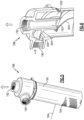
- FIG 5 shows a deaerator embodiment 188.
- a line 190 receives an air/oil mixture such as from the pump 72. Air leaves through an air outlet 192, as shown in Figure 4 .
- a plurality of oil outlets 194 are shown in an outer shell 195 of the deaerator.
- An oil level 196 is shown schematically, and would be the oil level within the oil tank 90 of Figure 4 .
- a flow splitter or separator 200 is provided inline to the inlet 190 and serves to split the air/oil flow into two paths, and at an intermediate location in inlet 190. This will hasten the deaeration of the mixed oil and air from the inlet 190. The air will be at the radially outer locations, and will pass through a tube 193 into the air outlet 192. As shown, air outlet 192 has an end 300 extending into a shell 302 of deaerator 188.
- the oil will flow downwardly along an upper path 202 of a scroll or spiral, and along a lower path 204. Although shown as vertically upper and lower sides, other opposed side orientations may be used.
- the inventive deaerator more quickly removes the oil, and thus facilitates the dwell times as mentioned above.
- a deaerator exit 194 delivers oil into the oil tank 90 at least 2 inches (5.08 centimeters) below a freestanding oil level 196 within the tank 90.
- An inlet velocity to the deaerator 188 is less than or equal to 14 feet/second (4.27 m/s).
- An exit velocity from the deaerator 188 into the air outlet 192 is less than or equal to 14 feet/second (4.27 m/s).
- Applicant has found that introducing the oil and air mixture into an oil tank is much "quieter,” resulting in less re-aeration when it is delivered at least two inches (5.08 cm) below a free surface. As an example, if the oil were sprayed into the free surface, this could cause splashing and foaming.
Landscapes
- Engineering & Computer Science (AREA)
- General Engineering & Computer Science (AREA)
- Chemical & Material Sciences (AREA)
- Combustion & Propulsion (AREA)
- Mechanical Engineering (AREA)
- General Details Of Gearings (AREA)
- Retarders (AREA)
- Lubrication Details And Ventilation Of Internal Combustion Engines (AREA)
Claims (5)
- Procédé de fonctionnement d'un moteur à turbine à gaz (20) comprenant :l'entraînement d'un réducteur de vitesse (48) à l'aide d'une turbine d'entraînement de ventilateur, ledit réducteur de vitesse (48) étant destiné à entraîner un rotor de ventilateur (42) ;l'alimentation en huile audit réducteur (48) à l'aide d'un système de lubrification (70), avec un réservoir d'huile (90), le système de lubrification (70) comportant une pompe à lubrifiant (72) ; etl'alimentation d'un mélange d'air et d'huile à une entrée (190) d'un désaérateur (88, 188), ledit désaérateur (88, 188) comportant un séparateur (200) pour séparer l'huile, et la fourniture de l'air séparé à une sortie d'air (192), et le renvoi d'huile séparée dans un réservoir d'huile (90) ;caractérisé en ce que :ledit séparateur (200) comporte un élément présentant des trajets d'écoulement de lubrifiant (202, 204) sur chacun des deux côtés opposés ;une vitesse d'entrée dans le désaérateur (88, 188) est inférieure ou égale à 14 pieds/seconde (4,27 m/s), et une vitesse de sortie du désaérateur (88, 188) de l'air séparé est inférieure ou égale à 14 pieds/seconde (4,27 m/s) ;ledit réducteur (48) comprend un planétaire (101) pour entraîner des engrenages intermédiaires (102) et des chicanes d'huile (100) sont situées circonférentiellement entre lesdits engrenages intermédiaires (102) ;une gouttière de récupération d'huile (104) entoure ledit réducteur (48) ; etun temps de séjour de l'huile dans le réservoir d'huile (90) telle qu'éliminée par ladite pompe à lubrifiant (72), en moyenne, est de cinq secondes ou moins.
- Procédé selon la revendication 1, dans lequel ledit séparateur (200) se trouve à une position intermédiaire dans ladite entrée (190).
- Procédé selon la revendication 1 ou 2, dans lequel ladite sortie d'air (192) présente un tube (193) se prolongeant vers le bas dans une coque de désaérateur (302).
- Procédé selon l'une quelconque des revendications précédentes, dans lequel ledit séparateur (200) comporte une spirale se prolongeant de ladite entrée (190) à la sortie du désaérateur (194).
- Procédé selon la revendication 4, dans lequel ladite sortie (194) comporte une pluralité de trous dans une coque.
Priority Applications (1)
| Application Number | Priority Date | Filing Date | Title |
|---|---|---|---|
| EP25175827.2A EP4575205A3 (fr) | 2014-07-01 | 2015-06-29 | Moteur à turbine à gaz à engrenages avec désaérateur d'huile |
Applications Claiming Priority (2)
| Application Number | Priority Date | Filing Date | Title |
|---|---|---|---|
| US201462019452P | 2014-07-01 | 2014-07-01 | |
| EP15174299.6A EP2963249B1 (fr) | 2014-07-01 | 2015-06-29 | Moteur à turbine à gaz avec soufflante à engrenage et désaérateur d'huile |
Related Parent Applications (2)
| Application Number | Title | Priority Date | Filing Date |
|---|---|---|---|
| EP15174299.6A Division EP2963249B1 (fr) | 2014-07-01 | 2015-06-29 | Moteur à turbine à gaz avec soufflante à engrenage et désaérateur d'huile |
| EP15174299.6A Division-Into EP2963249B1 (fr) | 2014-07-01 | 2015-06-29 | Moteur à turbine à gaz avec soufflante à engrenage et désaérateur d'huile |
Related Child Applications (1)
| Application Number | Title | Priority Date | Filing Date |
|---|---|---|---|
| EP25175827.2A Division EP4575205A3 (fr) | 2014-07-01 | 2015-06-29 | Moteur à turbine à gaz à engrenages avec désaérateur d'huile |
Publications (2)
| Publication Number | Publication Date |
|---|---|
| EP3693564A1 EP3693564A1 (fr) | 2020-08-12 |
| EP3693564B1 true EP3693564B1 (fr) | 2025-05-14 |
Family
ID=53886821
Family Applications (3)
| Application Number | Title | Priority Date | Filing Date |
|---|---|---|---|
| EP15174299.6A Active EP2963249B1 (fr) | 2014-07-01 | 2015-06-29 | Moteur à turbine à gaz avec soufflante à engrenage et désaérateur d'huile |
| EP20166697.1A Active EP3693564B1 (fr) | 2014-07-01 | 2015-06-29 | Procédé d'operation d'un moteur à turbine à gaz à engrenages avec désaérateur d'huile |
| EP25175827.2A Pending EP4575205A3 (fr) | 2014-07-01 | 2015-06-29 | Moteur à turbine à gaz à engrenages avec désaérateur d'huile |
Family Applications Before (1)
| Application Number | Title | Priority Date | Filing Date |
|---|---|---|---|
| EP15174299.6A Active EP2963249B1 (fr) | 2014-07-01 | 2015-06-29 | Moteur à turbine à gaz avec soufflante à engrenage et désaérateur d'huile |
Family Applications After (1)
| Application Number | Title | Priority Date | Filing Date |
|---|---|---|---|
| EP25175827.2A Pending EP4575205A3 (fr) | 2014-07-01 | 2015-06-29 | Moteur à turbine à gaz à engrenages avec désaérateur d'huile |
Country Status (2)
| Country | Link |
|---|---|
| US (4) | US9976490B2 (fr) |
| EP (3) | EP2963249B1 (fr) |
Families Citing this family (24)
| Publication number | Priority date | Publication date | Assignee | Title |
|---|---|---|---|---|
| CA2920482A1 (fr) * | 2013-08-16 | 2015-02-19 | General Electric Company | Deflecteur de tourbillons d'ecoulement |
| US10634061B2 (en) * | 2014-03-06 | 2020-04-28 | United Technologies Corporation | Gas turbine engine accessory architecture |
| FR3020658B1 (fr) * | 2014-04-30 | 2020-05-15 | Safran Aircraft Engines | Capot de recuperation d'huile de lubrification pour un equipement de turbomachine |
| US9976490B2 (en) * | 2014-07-01 | 2018-05-22 | United Technologies Corporation | Geared gas turbine engine with oil deaerator |
| FR3044044B1 (fr) * | 2015-11-19 | 2021-01-29 | Snecma | Systeme d'alimentation en fluide d'au moins un organe d'un ensemble propulsif d'aeronef |
| US10669948B2 (en) * | 2017-01-03 | 2020-06-02 | Raytheon Technologies Corporation | Geared turbofan with non-epicyclic gear reduction system |
| US10612436B2 (en) | 2017-09-26 | 2020-04-07 | United Technologies Corporation | Deoiler for a gas turbine engine |
| US11506079B2 (en) * | 2019-09-09 | 2022-11-22 | Raytheon Technologies Corporation | Fluid diffusion device for sealed bearing compartment drainback system |
| US11970972B2 (en) | 2019-10-23 | 2024-04-30 | Rtx Corporation | Windage blocker for oil routing |
| US11719127B2 (en) | 2019-10-23 | 2023-08-08 | Raytheon Technologies Corporation | Oil drainback assembly for a bearing compartment of a gas turbine engine |
| US11692669B2 (en) | 2019-11-22 | 2023-07-04 | Rolls-Royce Corporation | Oil tank filler cap integrated into the de-aerator |
| US12017157B2 (en) | 2021-01-22 | 2024-06-25 | Pratt & Whitney Canada Corp. | Deaerator for aircraft engine and associated method of operation |
| US12421898B2 (en) * | 2022-06-22 | 2025-09-23 | General Electric Company | Gearbox assembly with lubricant extraction volume ratio |
| US12345201B2 (en) * | 2022-06-22 | 2025-07-01 | General Electric Company | Gearbox assembly with lubricant extraction volume ratio |
| GB202210506D0 (en) * | 2022-07-18 | 2022-08-31 | Rolls Royce Plc | Aircraft propulsion system |
| US11867357B1 (en) | 2022-09-09 | 2024-01-09 | Pratt & Whitney Canada Corp. | Deaeration conduit |
| US12330089B2 (en) | 2022-09-09 | 2025-06-17 | Pratt & Whitney Canada Corp. | Dynamic deaeration system |
| GB202214143D0 (en) | 2022-09-28 | 2022-11-09 | Rolls Royce Plc | Gas turbine engine with an improved thermal management system |
| GB202214153D0 (en) | 2022-09-28 | 2022-11-09 | Rolls Royce Plc | Modulated heat management for geared gas turbine engines |
| GB202214148D0 (en) | 2022-09-28 | 2022-11-09 | Rolls Royce Plc | Gas turbine engine with improved heat management |
| GB202214144D0 (en) * | 2022-09-28 | 2022-11-09 | Rolls Royce Plc | Thermal management system for a gas turbine engine |
| US12031463B1 (en) * | 2023-05-31 | 2024-07-09 | Deltahawk Engines, Inc. | Separator for liquid and gas |
| US12448920B2 (en) * | 2023-10-20 | 2025-10-21 | Pratt & Whitney Canada Corp. | Oil de-aerator for aircraft engine |
| US12492649B2 (en) | 2024-05-06 | 2025-12-09 | General Electric Company | Lubrication system and methods of lubricating a gearbox assembly |
Family Cites Families (109)
| Publication number | Priority date | Publication date | Assignee | Title |
|---|---|---|---|---|
| US2258792A (en) | 1941-04-12 | 1941-10-14 | Westinghouse Electric & Mfg Co | Turbine blading |
| US3021731A (en) | 1951-11-10 | 1962-02-20 | Wilhelm G Stoeckicht | Planetary gear transmission |
| US2936655A (en) | 1955-11-04 | 1960-05-17 | Gen Motors Corp | Self-aligning planetary gearing |
| US3194487A (en) | 1963-06-04 | 1965-07-13 | United Aircraft Corp | Noise abatement method and apparatus |
| US3287906A (en) | 1965-07-20 | 1966-11-29 | Gen Motors Corp | Cooled gas turbine vanes |
| US3352178A (en) | 1965-11-15 | 1967-11-14 | Gen Motors Corp | Planetary gearing |
| US3412560A (en) | 1966-08-03 | 1968-11-26 | Gen Motors Corp | Jet propulsion engine with cooled combustion chamber, fuel heater, and induced air-flow |
| US3664612A (en) | 1969-12-22 | 1972-05-23 | Boeing Co | Aircraft engine variable highlight inlet |
| GB1350431A (en) | 1971-01-08 | 1974-04-18 | Secr Defence | Gearing |
| US3892358A (en) | 1971-03-17 | 1975-07-01 | Gen Electric | Nozzle seal |
| US3765623A (en) | 1971-10-04 | 1973-10-16 | Mc Donnell Douglas Corp | Air inlet |
| US3747343A (en) | 1972-02-10 | 1973-07-24 | United Aircraft Corp | Low noise prop-fan |
| GB1418905A (en) | 1972-05-09 | 1975-12-24 | Rolls Royce | Gas turbine engines |
| US3843277A (en) | 1973-02-14 | 1974-10-22 | Gen Electric | Sound attenuating inlet duct |
| US3988889A (en) | 1974-02-25 | 1976-11-02 | General Electric Company | Cowling arrangement for a turbofan engine |
| US3932058A (en) | 1974-06-07 | 1976-01-13 | United Technologies Corporation | Control system for variable pitch fan propulsor |
| US3935558A (en) | 1974-12-11 | 1976-01-27 | United Technologies Corporation | Surge detector for turbine engines |
| US4130872A (en) | 1975-10-10 | 1978-12-19 | The United States Of America As Represented By The Secretary Of The Air Force | Method and system of controlling a jet engine for avoiding engine surge |
| GB1516041A (en) | 1977-02-14 | 1978-06-28 | Secr Defence | Multistage axial flow compressor stators |
| US4240250A (en) | 1977-12-27 | 1980-12-23 | The Boeing Company | Noise reducing air inlet for gas turbine engines |
| GB2041090A (en) | 1979-01-31 | 1980-09-03 | Rolls Royce | By-pass gas turbine engines |
| US4284174A (en) | 1979-04-18 | 1981-08-18 | Avco Corporation | Emergency oil/mist system |
| US4220171A (en) | 1979-05-14 | 1980-09-02 | The United States Of America As Represented By The Administrator Of The National Aeronautics And Space Administration | Curved centerline air intake for a gas turbine engine |
| US4289360A (en) | 1979-08-23 | 1981-09-15 | General Electric Company | Bearing damper system |
| DE2940446C2 (de) | 1979-10-05 | 1982-07-08 | B. Braun Melsungen Ag, 3508 Melsungen | Züchtung von tierischen Zellen in Suspensions- und Monolayerkulturen in Fermentationsgefäßen |
| US4478551A (en) | 1981-12-08 | 1984-10-23 | United Technologies Corporation | Turbine exhaust case design |
| US4722357A (en) | 1986-04-11 | 1988-02-02 | United Technologies Corporation | Gas turbine engine nacelle |
| US4696156A (en) | 1986-06-03 | 1987-09-29 | United Technologies Corporation | Fuel and oil heat management system for a gas turbine engine |
| US4979362A (en) | 1989-05-17 | 1990-12-25 | Sundstrand Corporation | Aircraft engine starting and emergency power generating system |
| US5058617A (en) | 1990-07-23 | 1991-10-22 | General Electric Company | Nacelle inlet for an aircraft gas turbine engine |
| US5141400A (en) | 1991-01-25 | 1992-08-25 | General Electric Company | Wide chord fan blade |
| US5102379A (en) | 1991-03-25 | 1992-04-07 | United Technologies Corporation | Journal bearing arrangement |
| US5326468A (en) * | 1992-03-02 | 1994-07-05 | Cox Dale W | Water remediation and purification method and apparatus |
| US5317877A (en) | 1992-08-03 | 1994-06-07 | General Electric Company | Intercooled turbine blade cooling air feed system |
| US5447411A (en) | 1993-06-10 | 1995-09-05 | Martin Marietta Corporation | Light weight fan blade containment system |
| US5466198A (en) | 1993-06-11 | 1995-11-14 | United Technologies Corporation | Geared drive system for a bladed propulsor |
| US5361580A (en) | 1993-06-18 | 1994-11-08 | General Electric Company | Gas turbine engine rotor support system |
| US5524847A (en) | 1993-09-07 | 1996-06-11 | United Technologies Corporation | Nacelle and mounting arrangement for an aircraft engine |
| US5472383A (en) * | 1993-12-27 | 1995-12-05 | United Technologies Corporation | Lubrication system for a planetary gear train |
| RU2082824C1 (ru) | 1994-03-10 | 1997-06-27 | Московский государственный авиационный институт (технический университет) | Способ защиты жаропрочных материалов от воздействия агрессивных сред высокоскоростных газовых потоков (варианты) |
| US5433674A (en) | 1994-04-12 | 1995-07-18 | United Technologies Corporation | Coupling system for a planetary gear train |
| US5778659A (en) | 1994-10-20 | 1998-07-14 | United Technologies Corporation | Variable area fan exhaust nozzle having mechanically separate sleeve and thrust reverser actuation systems |
| WO1997000381A1 (fr) | 1994-12-14 | 1997-01-03 | United Technologies Corporation | Limitation du decrochage tournant et des cretes dans un compresseur, a l'aide de mesures d'asymetrie d'ecoulement d'air |
| JP2969075B2 (ja) | 1996-02-26 | 1999-11-02 | ジャパンゴアテックス株式会社 | 脱気装置 |
| US5634767A (en) | 1996-03-29 | 1997-06-03 | General Electric Company | Turbine frame having spindle mounted liner |
| US5975257A (en) * | 1996-09-04 | 1999-11-02 | Komatsu Mining Systems Inc. | Method and apparatus for separating steering oil and brake cooling oil within a hydraulic tank |
| US5857836A (en) | 1996-09-10 | 1999-01-12 | Aerodyne Research, Inc. | Evaporatively cooled rotor for a gas turbine engine |
| US5975841A (en) | 1997-10-03 | 1999-11-02 | Thermal Corp. | Heat pipe cooling for turbine stators |
| US5985470A (en) | 1998-03-16 | 1999-11-16 | General Electric Company | Thermal/environmental barrier coating system for silicon-based materials |
| US6517341B1 (en) | 1999-02-26 | 2003-02-11 | General Electric Company | Method to prevent recession loss of silica and silicon-containing materials in combustion gas environments |
| US6410148B1 (en) | 1999-04-15 | 2002-06-25 | General Electric Co. | Silicon based substrate with environmental/ thermal barrier layer |
| US6315815B1 (en) | 1999-12-16 | 2001-11-13 | United Technologies Corporation | Membrane based fuel deoxygenator |
| US6223616B1 (en) * | 1999-12-22 | 2001-05-01 | United Technologies Corporation | Star gear system with lubrication circuit and lubrication method therefor |
| US6134930A (en) * | 2000-01-26 | 2000-10-24 | Morgan Construction Company | Lubrication system |
| US6318070B1 (en) | 2000-03-03 | 2001-11-20 | United Technologies Corporation | Variable area nozzle for gas turbine engines driven by shape memory alloy actuators |
| US6444335B1 (en) | 2000-04-06 | 2002-09-03 | General Electric Company | Thermal/environmental barrier coating for silicon-containing materials |
| GB0016179D0 (en) | 2000-06-30 | 2000-08-23 | Lucas Industries Ltd | Deaerator |
| EP1780387A3 (fr) | 2000-09-05 | 2007-07-18 | Sudarshan Paul Dev | Turbine à gaz à coeur emboîté |
| US20020162970A1 (en) * | 2001-05-02 | 2002-11-07 | Michael Sasges | Optical sensing and control of ultraviolet fluid treatment dynamics |
| US7001448B1 (en) * | 2001-06-13 | 2006-02-21 | National Tank Company | System employing a vortex finder tube for separating a liquid component from a gas stream |
| US6708482B2 (en) | 2001-11-29 | 2004-03-23 | General Electric Company | Aircraft engine with inter-turbine engine frame |
| US6607165B1 (en) | 2002-06-28 | 2003-08-19 | General Electric Company | Aircraft engine mount with single thrust link |
| US6814541B2 (en) | 2002-10-07 | 2004-11-09 | General Electric Company | Jet aircraft fan case containment design |
| US7021042B2 (en) | 2002-12-13 | 2006-04-04 | United Technologies Corporation | Geartrain coupling for a turbofan engine |
| US6709492B1 (en) | 2003-04-04 | 2004-03-23 | United Technologies Corporation | Planar membrane deoxygenator |
| DE102004016246A1 (de) | 2004-04-02 | 2005-10-20 | Mtu Aero Engines Gmbh | Turbine, insbesondere Niederdruckturbine, einer Gasturbine, insbesondere eines Flugtriebwerks |
| US7328580B2 (en) | 2004-06-23 | 2008-02-12 | General Electric Company | Chevron film cooled wall |
| GB0414344D0 (en) * | 2004-06-26 | 2004-07-28 | Rolls Royce Plc | Centrifugal gas/liquid separators |
| GB0506685D0 (en) | 2005-04-01 | 2005-05-11 | Hopkins David R | A design to increase and smoothly improve the throughput of fluid (air or gas) through the inlet fan (or fans) of an aero-engine system |
| US7374403B2 (en) | 2005-04-07 | 2008-05-20 | General Electric Company | Low solidity turbofan |
| EP1928952B1 (fr) | 2005-09-28 | 2014-07-09 | Entrotech Composites, LLC. | Composite renforce d'une tresse et processus de fabrication |
| US7591754B2 (en) | 2006-03-22 | 2009-09-22 | United Technologies Corporation | Epicyclic gear train integral sun gear coupling design |
| BE1017135A3 (nl) | 2006-05-11 | 2008-03-04 | Hansen Transmissions Int | Een tandwielkast voor een windturbine. |
| US20080003096A1 (en) | 2006-06-29 | 2008-01-03 | United Technologies Corporation | High coverage cooling hole shape |
| JP4911344B2 (ja) | 2006-07-04 | 2012-04-04 | 株式会社Ihi | ターボファンエンジン |
| US8585538B2 (en) | 2006-07-05 | 2013-11-19 | United Technologies Corporation | Coupling system for a star gear train in a gas turbine engine |
| US7704178B2 (en) * | 2006-07-05 | 2010-04-27 | United Technologies Corporation | Oil baffle for gas turbine fan drive gear system |
| US7926260B2 (en) | 2006-07-05 | 2011-04-19 | United Technologies Corporation | Flexible shaft for gas turbine engine |
| US7632064B2 (en) | 2006-09-01 | 2009-12-15 | United Technologies Corporation | Variable geometry guide vane for a gas turbine engine |
| EP2415507A1 (fr) * | 2006-09-26 | 2012-02-08 | Dresser-Rand Company | Dispositif de séparation de fluides statique amélioré |
| US7662059B2 (en) | 2006-10-18 | 2010-02-16 | United Technologies Corporation | Lubrication of windmilling journal bearings |
| US8020665B2 (en) | 2006-11-22 | 2011-09-20 | United Technologies Corporation | Lubrication system with extended emergency operability |
| US8017188B2 (en) | 2007-04-17 | 2011-09-13 | General Electric Company | Methods of making articles having toughened and untoughened regions |
| US7950237B2 (en) | 2007-06-25 | 2011-05-31 | United Technologies Corporation | Managing spool bearing load using variable area flow nozzle |
| WO2009006672A1 (fr) * | 2007-07-12 | 2009-01-15 | Commonwealth Scientific And Industrial Research Organisation | Séparateur fluide-fluide |
| US20120124964A1 (en) | 2007-07-27 | 2012-05-24 | Hasel Karl L | Gas turbine engine with improved fuel efficiency |
| US8256707B2 (en) | 2007-08-01 | 2012-09-04 | United Technologies Corporation | Engine mounting configuration for a turbofan gas turbine engine |
| US8205432B2 (en) | 2007-10-03 | 2012-06-26 | United Technologies Corporation | Epicyclic gear train for turbo fan engine |
| US7963371B2 (en) * | 2008-04-30 | 2011-06-21 | National Oilwell Varco, L.P. | Centrifugal applicator system |
| US8128021B2 (en) | 2008-06-02 | 2012-03-06 | United Technologies Corporation | Engine mount system for a turbofan gas turbine engine |
| DE102008044440B4 (de) * | 2008-08-18 | 2011-03-03 | Lurgi Zimmer Gmbh | Verfahren und Vorrichtung zur Rückgewinnung von Ethylenglykol bei der Polyethylenterephthalatherstellung |
| US8181746B2 (en) * | 2008-09-18 | 2012-05-22 | United Technologies Corporation | Continuous supply fluid reservoir |
| US7997868B1 (en) | 2008-11-18 | 2011-08-16 | Florida Turbine Technologies, Inc. | Film cooling hole for turbine airfoil |
| US8307626B2 (en) | 2009-02-26 | 2012-11-13 | United Technologies Corporation | Auxiliary pump system for fan drive gear system |
| US8181441B2 (en) | 2009-02-27 | 2012-05-22 | United Technologies Corporation | Controlled fan stream flow bypass |
| US8172716B2 (en) | 2009-06-25 | 2012-05-08 | United Technologies Corporation | Epicyclic gear system with superfinished journal bearing |
| US9170616B2 (en) | 2009-12-31 | 2015-10-27 | Intel Corporation | Quiet system cooling using coupled optimization between integrated micro porous absorbers and rotors |
| US8905713B2 (en) | 2010-05-28 | 2014-12-09 | General Electric Company | Articles which include chevron film cooling holes, and related processes |
| EP2573338B1 (fr) * | 2011-09-20 | 2017-07-19 | Safran Aero Boosters SA | Contrôle du sur-remplissage d'un système de lubrification d'un moteur d'aéronef |
| US9028576B2 (en) * | 2011-11-09 | 2015-05-12 | Hamilton Sundstrand Corporation | Gearbox deoiler with pre-pressuring component |
| EP2806959A1 (fr) * | 2012-01-25 | 2014-12-03 | Acal Energy Limited | Régénérateur et séparateur améliorés d'électrolyte de pile à combustible |
| US8500869B1 (en) * | 2012-06-21 | 2013-08-06 | Hamilton Sundstrand Corporation | Anti-rotation deaerator outlet diffuser |
| US20140140824A1 (en) * | 2012-10-26 | 2014-05-22 | United Technologies Corporation | Oil system bearing compartment architecture for gas turbine engine |
| US20140219868A1 (en) * | 2013-02-04 | 2014-08-07 | Horiba Stec, Co., Ltd. | Reaction apparatus, control device, and control program |
| US9016138B2 (en) * | 2013-03-13 | 2015-04-28 | Rosemount Inc. | Flanged reducer vortex flowmeter |
| US10345199B2 (en) * | 2013-03-14 | 2019-07-09 | Sobru Solutions, Inc. | Sample acquisition system and method of use |
| FR3016406B1 (fr) * | 2014-01-10 | 2016-02-12 | Snecma | Ensemble de turbomachine comportant deux corps et des moyens de guidage d'un fluide d'ecoulement d'un corps a l'autre |
| US9976490B2 (en) * | 2014-07-01 | 2018-05-22 | United Technologies Corporation | Geared gas turbine engine with oil deaerator |
| AT517483B1 (de) * | 2015-06-25 | 2017-02-15 | Ge Jenbacher Gmbh & Co Og | Ölversorgungssystem für eine Brennkraftmaschine |
-
2015
- 2015-06-12 US US14/737,670 patent/US9976490B2/en active Active
- 2015-06-29 EP EP15174299.6A patent/EP2963249B1/fr active Active
- 2015-06-29 EP EP20166697.1A patent/EP3693564B1/fr active Active
- 2015-06-29 EP EP25175827.2A patent/EP4575205A3/fr active Pending
-
2018
- 2018-01-18 US US15/873,961 patent/US20180238242A1/en not_active Abandoned
- 2018-08-10 US US16/100,930 patent/US20190063330A1/en not_active Abandoned
-
2020
- 2020-10-30 US US17/085,616 patent/US11725589B2/en active Active
Also Published As
| Publication number | Publication date |
|---|---|
| US20190063330A1 (en) | 2019-02-28 |
| US9976490B2 (en) | 2018-05-22 |
| EP2963249A1 (fr) | 2016-01-06 |
| US20210231059A1 (en) | 2021-07-29 |
| US20180238242A1 (en) | 2018-08-23 |
| EP2963249B1 (fr) | 2020-05-13 |
| EP4575205A2 (fr) | 2025-06-25 |
| EP3693564A1 (fr) | 2020-08-12 |
| US20160017812A1 (en) | 2016-01-21 |
| US11725589B2 (en) | 2023-08-15 |
| EP4575205A3 (fr) | 2025-09-10 |
Similar Documents
| Publication | Publication Date | Title |
|---|---|---|
| US11725589B2 (en) | Geared gas turbine engine with oil deaerator | |
| US12018574B2 (en) | Geared gas turbine engine with oil deaerator and air removal | |
| EP3617479B1 (fr) | Moteur à turbine à gaz à engrenages présentant une taille de réservoir d'huile réduite | |
| US11067162B2 (en) | Geared architecture gas turbine engine with oil scavenge | |
| EP3102807B1 (fr) | Système d'huile auxiliaire pour un moteur à turbine à gaz à engrenages | |
| EP3109434B1 (fr) | Échangeur de chaleur avec un conduit de dérivation de ventilateur commandé | |
| EP3061992B1 (fr) | Dispositif de dégazage en ligne pour système d'huile auxiliaire d'éolienne pour système d'engrenage d'entraînement de ventilateur | |
| US10202902B2 (en) | Geared architecture gas turbine engine with oil scavenge |
Legal Events
| Date | Code | Title | Description |
|---|---|---|---|
| PUAI | Public reference made under article 153(3) epc to a published international application that has entered the european phase |
Free format text: ORIGINAL CODE: 0009012 |
|
| STAA | Information on the status of an ep patent application or granted ep patent |
Free format text: STATUS: THE APPLICATION HAS BEEN PUBLISHED |
|
| AC | Divisional application: reference to earlier application |
Ref document number: 2963249 Country of ref document: EP Kind code of ref document: P |
|
| AK | Designated contracting states |
Kind code of ref document: A1 Designated state(s): AL AT BE BG CH CY CZ DE DK EE ES FI FR GB GR HR HU IE IS IT LI LT LU LV MC MK MT NL NO PL PT RO RS SE SI SK SM TR |
|
| STAA | Information on the status of an ep patent application or granted ep patent |
Free format text: STATUS: REQUEST FOR EXAMINATION WAS MADE |
|
| 17P | Request for examination filed |
Effective date: 20210212 |
|
| RAP1 | Party data changed (applicant data changed or rights of an application transferred) |
Owner name: RAYTHEON TECHNOLOGIES CORPORATION |
|
| RBV | Designated contracting states (corrected) |
Designated state(s): AL AT BE BG CH CY CZ DE DK EE ES FI FR GB GR HR HU IE IS IT LI LT LU LV MC MK MT NL NO PL PT RO RS SE SI SK SM TR |
|
| STAA | Information on the status of an ep patent application or granted ep patent |
Free format text: STATUS: EXAMINATION IS IN PROGRESS |
|
| 17Q | First examination report despatched |
Effective date: 20220602 |
|
| RAP3 | Party data changed (applicant data changed or rights of an application transferred) |
Owner name: RTX CORPORATION |
|
| GRAP | Despatch of communication of intention to grant a patent |
Free format text: ORIGINAL CODE: EPIDOSNIGR1 |
|
| STAA | Information on the status of an ep patent application or granted ep patent |
Free format text: STATUS: GRANT OF PATENT IS INTENDED |
|
| RIC1 | Information provided on ipc code assigned before grant |
Ipc: F02C 7/06 20060101ALI20241119BHEP Ipc: F01M 13/04 20060101ALI20241119BHEP Ipc: F01D 25/20 20060101ALI20241119BHEP Ipc: F16N 39/00 20060101ALI20241119BHEP Ipc: F02C 7/36 20060101ALI20241119BHEP Ipc: F01D 25/18 20060101AFI20241119BHEP |
|
| INTG | Intention to grant announced |
Effective date: 20241203 |
|
| GRAS | Grant fee paid |
Free format text: ORIGINAL CODE: EPIDOSNIGR3 |
|
| GRAA | (expected) grant |
Free format text: ORIGINAL CODE: 0009210 |
|
| STAA | Information on the status of an ep patent application or granted ep patent |
Free format text: STATUS: THE PATENT HAS BEEN GRANTED |
|
| AC | Divisional application: reference to earlier application |
Ref document number: 2963249 Country of ref document: EP Kind code of ref document: P |
|
| AK | Designated contracting states |
Kind code of ref document: B1 Designated state(s): AL AT BE BG CH CY CZ DE DK EE ES FI FR GB GR HR HU IE IS IT LI LT LU LV MC MK MT NL NO PL PT RO RS SE SI SK SM TR |
|
| REG | Reference to a national code |
Ref country code: GB Ref legal event code: FG4D |
|
| REG | Reference to a national code |
Ref country code: CH Ref legal event code: EP |
|
| REG | Reference to a national code |
Ref country code: DE Ref legal event code: R096 Ref document number: 602015091675 Country of ref document: DE |
|
| REG | Reference to a national code |
Ref country code: IE Ref legal event code: FG4D |
|
| PGFP | Annual fee paid to national office [announced via postgrant information from national office to epo] |
Ref country code: DE Payment date: 20250520 Year of fee payment: 11 |
|
| PGFP | Annual fee paid to national office [announced via postgrant information from national office to epo] |
Ref country code: GB Payment date: 20250619 Year of fee payment: 11 |
|
| PGFP | Annual fee paid to national office [announced via postgrant information from national office to epo] |
Ref country code: FR Payment date: 20250619 Year of fee payment: 11 |
|
| REG | Reference to a national code |
Ref country code: NL Ref legal event code: MP Effective date: 20250514 |
|
| PG25 | Lapsed in a contracting state [announced via postgrant information from national office to epo] |
Ref country code: FI Free format text: LAPSE BECAUSE OF FAILURE TO SUBMIT A TRANSLATION OF THE DESCRIPTION OR TO PAY THE FEE WITHIN THE PRESCRIBED TIME-LIMIT Effective date: 20250514 Ref country code: PT Free format text: LAPSE BECAUSE OF FAILURE TO SUBMIT A TRANSLATION OF THE DESCRIPTION OR TO PAY THE FEE WITHIN THE PRESCRIBED TIME-LIMIT Effective date: 20250915 Ref country code: ES Free format text: LAPSE BECAUSE OF FAILURE TO SUBMIT A TRANSLATION OF THE DESCRIPTION OR TO PAY THE FEE WITHIN THE PRESCRIBED TIME-LIMIT Effective date: 20250514 |
|
| REG | Reference to a national code |
Ref country code: LT Ref legal event code: MG9D |
|
| PG25 | Lapsed in a contracting state [announced via postgrant information from national office to epo] |
Ref country code: NO Free format text: LAPSE BECAUSE OF FAILURE TO SUBMIT A TRANSLATION OF THE DESCRIPTION OR TO PAY THE FEE WITHIN THE PRESCRIBED TIME-LIMIT Effective date: 20250814 Ref country code: GR Free format text: LAPSE BECAUSE OF FAILURE TO SUBMIT A TRANSLATION OF THE DESCRIPTION OR TO PAY THE FEE WITHIN THE PRESCRIBED TIME-LIMIT Effective date: 20250815 |
|
| PG25 | Lapsed in a contracting state [announced via postgrant information from national office to epo] |
Ref country code: PL Free format text: LAPSE BECAUSE OF FAILURE TO SUBMIT A TRANSLATION OF THE DESCRIPTION OR TO PAY THE FEE WITHIN THE PRESCRIBED TIME-LIMIT Effective date: 20250514 Ref country code: NL Free format text: LAPSE BECAUSE OF FAILURE TO SUBMIT A TRANSLATION OF THE DESCRIPTION OR TO PAY THE FEE WITHIN THE PRESCRIBED TIME-LIMIT Effective date: 20250514 |
|
| REG | Reference to a national code |
Ref country code: AT Ref legal event code: MK05 Ref document number: 1794923 Country of ref document: AT Kind code of ref document: T Effective date: 20250514 |
|
| PG25 | Lapsed in a contracting state [announced via postgrant information from national office to epo] |
Ref country code: BG Free format text: LAPSE BECAUSE OF FAILURE TO SUBMIT A TRANSLATION OF THE DESCRIPTION OR TO PAY THE FEE WITHIN THE PRESCRIBED TIME-LIMIT Effective date: 20250514 |
|
| PG25 | Lapsed in a contracting state [announced via postgrant information from national office to epo] |
Ref country code: HR Free format text: LAPSE BECAUSE OF FAILURE TO SUBMIT A TRANSLATION OF THE DESCRIPTION OR TO PAY THE FEE WITHIN THE PRESCRIBED TIME-LIMIT Effective date: 20250514 |
|
| PG25 | Lapsed in a contracting state [announced via postgrant information from national office to epo] |
Ref country code: AT Free format text: LAPSE BECAUSE OF FAILURE TO SUBMIT A TRANSLATION OF THE DESCRIPTION OR TO PAY THE FEE WITHIN THE PRESCRIBED TIME-LIMIT Effective date: 20250514 |
|
| PG25 | Lapsed in a contracting state [announced via postgrant information from national office to epo] |
Ref country code: RS Free format text: LAPSE BECAUSE OF FAILURE TO SUBMIT A TRANSLATION OF THE DESCRIPTION OR TO PAY THE FEE WITHIN THE PRESCRIBED TIME-LIMIT Effective date: 20250814 |
|
| PG25 | Lapsed in a contracting state [announced via postgrant information from national office to epo] |
Ref country code: IS Free format text: LAPSE BECAUSE OF FAILURE TO SUBMIT A TRANSLATION OF THE DESCRIPTION OR TO PAY THE FEE WITHIN THE PRESCRIBED TIME-LIMIT Effective date: 20250914 |
|
| PG25 | Lapsed in a contracting state [announced via postgrant information from national office to epo] |
Ref country code: LV Free format text: LAPSE BECAUSE OF FAILURE TO SUBMIT A TRANSLATION OF THE DESCRIPTION OR TO PAY THE FEE WITHIN THE PRESCRIBED TIME-LIMIT Effective date: 20250514 |
|
| PG25 | Lapsed in a contracting state [announced via postgrant information from national office to epo] |
Ref country code: SM Free format text: LAPSE BECAUSE OF FAILURE TO SUBMIT A TRANSLATION OF THE DESCRIPTION OR TO PAY THE FEE WITHIN THE PRESCRIBED TIME-LIMIT Effective date: 20250514 Ref country code: DK Free format text: LAPSE BECAUSE OF FAILURE TO SUBMIT A TRANSLATION OF THE DESCRIPTION OR TO PAY THE FEE WITHIN THE PRESCRIBED TIME-LIMIT Effective date: 20250514 |
|
| PG25 | Lapsed in a contracting state [announced via postgrant information from national office to epo] |
Ref country code: CZ Free format text: LAPSE BECAUSE OF FAILURE TO SUBMIT A TRANSLATION OF THE DESCRIPTION OR TO PAY THE FEE WITHIN THE PRESCRIBED TIME-LIMIT Effective date: 20250514 |
|
| PG25 | Lapsed in a contracting state [announced via postgrant information from national office to epo] |
Ref country code: EE Free format text: LAPSE BECAUSE OF FAILURE TO SUBMIT A TRANSLATION OF THE DESCRIPTION OR TO PAY THE FEE WITHIN THE PRESCRIBED TIME-LIMIT Effective date: 20250514 |
|
| PG25 | Lapsed in a contracting state [announced via postgrant information from national office to epo] |
Ref country code: SK Free format text: LAPSE BECAUSE OF FAILURE TO SUBMIT A TRANSLATION OF THE DESCRIPTION OR TO PAY THE FEE WITHIN THE PRESCRIBED TIME-LIMIT Effective date: 20250514 Ref country code: RO Free format text: LAPSE BECAUSE OF FAILURE TO SUBMIT A TRANSLATION OF THE DESCRIPTION OR TO PAY THE FEE WITHIN THE PRESCRIBED TIME-LIMIT Effective date: 20250514 |
|
| REG | Reference to a national code |
Ref country code: CH Ref legal event code: H13 Free format text: ST27 STATUS EVENT CODE: U-0-0-H10-H13 (AS PROVIDED BY THE NATIONAL OFFICE) Effective date: 20260127 |
|
| PG25 | Lapsed in a contracting state [announced via postgrant information from national office to epo] |
Ref country code: IT Free format text: LAPSE BECAUSE OF FAILURE TO SUBMIT A TRANSLATION OF THE DESCRIPTION OR TO PAY THE FEE WITHIN THE PRESCRIBED TIME-LIMIT Effective date: 20250514 |
|
| PG25 | Lapsed in a contracting state [announced via postgrant information from national office to epo] |
Ref country code: LU Free format text: LAPSE BECAUSE OF NON-PAYMENT OF DUE FEES Effective date: 20250629 |
|
| REG | Reference to a national code |
Ref country code: DE Ref legal event code: R097 Ref document number: 602015091675 Country of ref document: DE |
|
| PG25 | Lapsed in a contracting state [announced via postgrant information from national office to epo] |
Ref country code: MC Free format text: LAPSE BECAUSE OF FAILURE TO SUBMIT A TRANSLATION OF THE DESCRIPTION OR TO PAY THE FEE WITHIN THE PRESCRIBED TIME-LIMIT Effective date: 20250514 |
|
| REG | Reference to a national code |
Ref country code: BE Ref legal event code: MM Effective date: 20250630 |
|
| PLBE | No opposition filed within time limit |
Free format text: ORIGINAL CODE: 0009261 |
|
| STAA | Information on the status of an ep patent application or granted ep patent |
Free format text: STATUS: NO OPPOSITION FILED WITHIN TIME LIMIT |
|
| REG | Reference to a national code |
Ref country code: CH Ref legal event code: L10 Free format text: ST27 STATUS EVENT CODE: U-0-0-L10-L00 (AS PROVIDED BY THE NATIONAL OFFICE) Effective date: 20260325 |
|
| PG25 | Lapsed in a contracting state [announced via postgrant information from national office to epo] |
Ref country code: IE Free format text: LAPSE BECAUSE OF NON-PAYMENT OF DUE FEES Effective date: 20250629 |
|
| PG25 | Lapsed in a contracting state [announced via postgrant information from national office to epo] |
Ref country code: BE Free format text: LAPSE BECAUSE OF NON-PAYMENT OF DUE FEES Effective date: 20250630 |
|
| 26N | No opposition filed |
Effective date: 20260217 |
|
| PG25 | Lapsed in a contracting state [announced via postgrant information from national office to epo] |
Ref country code: CH Free format text: LAPSE BECAUSE OF NON-PAYMENT OF DUE FEES Effective date: 20250630 |