EP3693607B1 - Systèmes et procédés pour une pompe de vidange connectée - Google Patents
Systèmes et procédés pour une pompe de vidange connectée Download PDFInfo
- Publication number
- EP3693607B1 EP3693607B1 EP19205740.4A EP19205740A EP3693607B1 EP 3693607 B1 EP3693607 B1 EP 3693607B1 EP 19205740 A EP19205740 A EP 19205740A EP 3693607 B1 EP3693607 B1 EP 3693607B1
- Authority
- EP
- European Patent Office
- Prior art keywords
- sump pump
- power
- power adapter
- pump
- float switch
- Prior art date
- Legal status (The legal status is an assumption and is not a legal conclusion. Google has not performed a legal analysis and makes no representation as to the accuracy of the status listed.)
- Active
Links
Images


Classifications
-
- H—ELECTRICITY
- H04—ELECTRIC COMMUNICATION TECHNIQUE
- H04W—WIRELESS COMMUNICATION NETWORKS
- H04W84/00—Network topologies
- H04W84/18—Self-organising networks, e.g. ad-hoc networks or sensor networks
-
- F—MECHANICAL ENGINEERING; LIGHTING; HEATING; WEAPONS; BLASTING
- F04—POSITIVE - DISPLACEMENT MACHINES FOR LIQUIDS; PUMPS FOR LIQUIDS OR ELASTIC FLUIDS
- F04D—NON-POSITIVE-DISPLACEMENT PUMPS
- F04D15/00—Control, e.g. regulation, of pumps, pumping installations or systems
- F04D15/02—Stopping of pumps, or operating valves, on occurrence of unwanted conditions
- F04D15/0209—Stopping of pumps, or operating valves, on occurrence of unwanted conditions responsive to a condition of the working fluid
- F04D15/0218—Stopping of pumps, or operating valves, on occurrence of unwanted conditions responsive to a condition of the working fluid the condition being a liquid level or a lack of liquid supply
-
- F—MECHANICAL ENGINEERING; LIGHTING; HEATING; WEAPONS; BLASTING
- F04—POSITIVE - DISPLACEMENT MACHINES FOR LIQUIDS; PUMPS FOR LIQUIDS OR ELASTIC FLUIDS
- F04B—POSITIVE-DISPLACEMENT MACHINES FOR LIQUIDS; PUMPS
- F04B23/00—Pumping installations or systems
- F04B23/02—Pumping installations or systems having reservoirs
- F04B23/021—Pumping installations or systems having reservoirs the pump being immersed in the reservoir
- F04B23/023—Pumping installations or systems having reservoirs the pump being immersed in the reservoir only the pump-part being immersed, the driving-part being outside the reservoir
-
- F—MECHANICAL ENGINEERING; LIGHTING; HEATING; WEAPONS; BLASTING
- F04—POSITIVE - DISPLACEMENT MACHINES FOR LIQUIDS; PUMPS FOR LIQUIDS OR ELASTIC FLUIDS
- F04B—POSITIVE-DISPLACEMENT MACHINES FOR LIQUIDS; PUMPS
- F04B49/00—Control, e.g. of pump delivery, or pump pressure of, or safety measures for, machines, pumps, or pumping installations, not otherwise provided for, or of interest apart from, groups F04B1/00 - F04B47/00
- F04B49/06—Control using electricity
- F04B49/065—Control using electricity and making use of computers
-
- F—MECHANICAL ENGINEERING; LIGHTING; HEATING; WEAPONS; BLASTING
- F04—POSITIVE - DISPLACEMENT MACHINES FOR LIQUIDS; PUMPS FOR LIQUIDS OR ELASTIC FLUIDS
- F04D—NON-POSITIVE-DISPLACEMENT PUMPS
- F04D13/00—Pumping installations or systems
- F04D13/02—Units comprising pumps and their driving means
- F04D13/06—Units comprising pumps and their driving means the pump being electrically driven
- F04D13/0686—Mechanical details of the pump control unit
-
- F—MECHANICAL ENGINEERING; LIGHTING; HEATING; WEAPONS; BLASTING
- F04—POSITIVE - DISPLACEMENT MACHINES FOR LIQUIDS; PUMPS FOR LIQUIDS OR ELASTIC FLUIDS
- F04D—NON-POSITIVE-DISPLACEMENT PUMPS
- F04D15/00—Control, e.g. regulation, of pumps, pumping installations or systems
- F04D15/02—Stopping of pumps, or operating valves, on occurrence of unwanted conditions
- F04D15/0209—Stopping of pumps, or operating valves, on occurrence of unwanted conditions responsive to a condition of the working fluid
- F04D15/0218—Stopping of pumps, or operating valves, on occurrence of unwanted conditions responsive to a condition of the working fluid the condition being a liquid level or a lack of liquid supply
- F04D15/0236—Lack of liquid level being detected by analysing the parameters of the electric drive, e.g. current or power consumption
-
- G—PHYSICS
- G06—COMPUTING OR CALCULATING; COUNTING
- G06F—ELECTRIC DIGITAL DATA PROCESSING
- G06F1/00—Details not covered by groups G06F3/00 - G06F13/00 and G06F21/00
- G06F1/26—Power supply means, e.g. regulation thereof
-
- G—PHYSICS
- G06—COMPUTING OR CALCULATING; COUNTING
- G06F—ELECTRIC DIGITAL DATA PROCESSING
- G06F1/00—Details not covered by groups G06F3/00 - G06F13/00 and G06F21/00
- G06F1/26—Power supply means, e.g. regulation thereof
- G06F1/266—Arrangements to supply power to external peripherals either directly from the computer or under computer control, e.g. supply of power through the communication port, computer controlled power-strips
-
- G—PHYSICS
- G06—COMPUTING OR CALCULATING; COUNTING
- G06F—ELECTRIC DIGITAL DATA PROCESSING
- G06F1/00—Details not covered by groups G06F3/00 - G06F13/00 and G06F21/00
- G06F1/26—Power supply means, e.g. regulation thereof
- G06F1/32—Means for saving power
- G06F1/3203—Power management, i.e. event-based initiation of a power-saving mode
- G06F1/3206—Monitoring of events, devices or parameters that trigger a change in power modality
- G06F1/3209—Monitoring remote activity, e.g. over telephone lines or network connections
-
- G—PHYSICS
- G07—CHECKING-DEVICES
- G07C—TIME OR ATTENDANCE REGISTERS; REGISTERING OR INDICATING THE WORKING OF MACHINES; GENERATING RANDOM NUMBERS; VOTING OR LOTTERY APPARATUS; ARRANGEMENTS, SYSTEMS OR APPARATUS FOR CHECKING NOT PROVIDED FOR ELSEWHERE
- G07C3/00—Registering or indicating the condition or the working of machines or other apparatus, other than vehicles
- G07C3/02—Registering or indicating working or idle time only
-
- H—ELECTRICITY
- H04—ELECTRIC COMMUNICATION TECHNIQUE
- H04W—WIRELESS COMMUNICATION NETWORKS
- H04W4/00—Services specially adapted for wireless communication networks; Facilities therefor
- H04W4/80—Services using short range communication, e.g. near-field communication [NFC], radio-frequency identification [RFID] or low energy communication
-
- H—ELECTRICITY
- H04—ELECTRIC COMMUNICATION TECHNIQUE
- H04W—WIRELESS COMMUNICATION NETWORKS
- H04W76/00—Connection management
- H04W76/10—Connection setup
- H04W76/15—Setup of multiple wireless link connections
Definitions
- Float switches are commonly used to automatically turn a sump pump on when water rises to a preset level.
- the float switches for sump pumps can have normally open relays, allowing the pump to be inactive when the float is in the lowered position, and to activate when the float is raised.
- Various types of float switches can be used with a sump pump, such as: vertical float switches, tethered float switches, and electronic float switches. Alternatively, in some situations, pressure switches can be used to control the sump pump.
- a tethered float is attached to a bent rod, mechanical trigger, or a cable. Similar to the vertical float, a tethered float triggers the pump to turn on and off based on the rise and fall of the fluid level.
- Electronic float switches are primarily used in sump pits which are too narrow to accommodate a tethered float or other float type. Electronic float switches have no moving parts and switch on and off when the switch detects a rise or fall in the water level.
- Float switches can be installed via a piggy-back plug.
- the power plug on the float switch can plug-in to a power outlet, and the pump power plug can plug into the piggy-back outlet on the back of the float power plug.
- Sump basins and sump pumps require regular maintenance. However, the frequency that the pump is used can dictate when maintenance is needed. Some pumps can run frequently due to higher water table, water drainage, or weather conditions. Sump pumps, being mechanical devices, can eventually wear out and/or require replacement. Early recognition of problems and subsequent correction can prevent an accidental shutdown of a sump pump. Some sump pumps can alert homeowners to maintenance issues via indicator lights and/or alarms. By nature, however, sump pumps are generally located in low-traffic areas (e.g., a corner of a basement). As such, indicator lights and alarms can go unnoticed if a homeowner does not actively check on the sump pump.
- US2006176000A1 discloses a control system for a sump pump driven by an AC motor includes an AC power line having an input adapted for connection to an AC power source and an output adapted for connection to the AC drive motor.
- a controller is connected to a controllable switch in the AC power line, to control the opening and closing of that switch. Redundant float switches are coupled to the controller and adapted to be mounted in a sump to supply the controller with a signals when the liquid in the sump rises to a selected level.
- a timer in, or coupled to, the controller alters the control signal to open the controllable switch if the liquid level in the sump remains above the selected level for a preselected time period.
- US2016284496A1 discloses a current sensing switch for use with a pump that is physically separate from the pump and contains a current sensor for measuring the electrical current flowing to the pump as a method of determining whether the pump is operating in low fluid or dry conditions. When the current drops below a predetermined value for a predetermined amount of time, the switch electrically disconnects power to the pump.
- systems and methods for monitoring operation of a sump pump are provided.
- the systems and methods of the invention overcome drawbacks of existing systems, including those described above, to provide individuals with the ability to monitor and control a sump pump, and in particular, to overcome the shortcomings relating to the health of the sump pump and the notification of individuals when a problem occurs.
- a system for monitoring operation of a float-switch controlled sump pump via a remote server includes a power adapter having a printed circuit board, the printed circuit board positioned within a housing.
- the power adapter includes a power supply in electrical communication with one or more components coupled to the printed circuit board, the power supply configured to receive electric power from one or more electric power inputs.
- the power adapter further includes an integrated chip coupled to the printed circuit board.
- the integrated chip is configured to establish a first wireless connection to a first wireless network, and transmit a message to a remote server over the first wireless network.
- the integrated chip is also configured to execute computer readable instructions.
- the power adapter includes a first receptacle positioned on the housing and configured to accept a float-switch input, the float-switch input in electrical communication with the printed circuit board upon insertion into the first receptacle.
- the power adapter further includes a second receptacle positioned on the housing and configured to accept a sump pump input, the sump pump input in electrical communication with the printed circuit board upon insertion into the second receptacle.
- a method for monitoring and controlling a float-switch controlled sump pump includes connecting a power adapter to the sump pump and a float-switch.
- the power adapter includes a printed circuit board (PCB) positioned within a housing, a power supply in electrical communication with components coupled to the PCB, and an integrated chip coupled to the PCB.
- the integrated chip is configured to establish a wireless connection to a first wireless network, and transmit a message to a remote server over the first wireless network.
- the method further includes causing an internet enabled device to send one or more instructions that causes the power adapter to connect to the first wireless network, and receiving, using the internet enabled device, a message from the remote server.
- a system for monitoring operation of a sump pump via a remote serve is provided in accordance with claim 1.
- Optional and/or preferable features are described in the dependent claims.
- the housing can include a mounting hole oriented to accept a screw for insertion into a duplex wall outlet to affix the power adapter to the duplex outlet.
- the power adapter can be configured to communicate with a user device and receive a request for a health test from the user device.
- communications to and/or from the power adapter 34, the router/modem 54, the cloud based server 56, and/or the internet enabled device can be sent over a communication network, which can be any suitable communication network or combination of communication networks.
- the communication network can include a Wi-Fi network (e.g., an 802.11x network, which can include one or more wireless routers, one or more switches, etc.), a peer-to-peer network (e.g., a Bluetooth network, a ZigBee ® network, a Z-Wave ® network, a proprietary RF connection, etc.), a cellular network (e.g., a 3G network, a 4G network, etc., complying with any suitable standard, such as CDMA, GSM, LTE, LTE Advanced, WiMAX, etc.), a wired network, an EnOcean ® network, etc.
- Wi-Fi network e.g., an 802.11x network, which can include one or more wireless routers, one or more
- the communication network can be a LAN, a WAN, a public network (e.g., the Internet), a private or semi-private network (e.g., a corporate or university intranet), any other suitable type of network, or any suitable combination of networks.
- Communications links between the power adapter 34, the router/modem 54, the cloud based server 56, and/or the internet enabled device can each be any suitable communications link or combination of communications links, such as wired links, fiber optic links, Wi-Fi links, Bluetooth links, cellular links, etc.
- the internet enabled device can communicate with the cloud based server 56 via any suitable network or combination of networks.
- the power adapter 34 can send and receive information (e.g., messages) to and from the internet enabled device (e.g., user device 58) via the cloud based server 56 or via a peer connection or mesh network.
- the integrated chip/PCB described above can coordinate operation of the float switch 6 and/or the sump pump 4, such as by controlling a relay to selectively provide power to sump pump 4 based on faults, user inputs, etc. Additionally or alternatively, in some embodiments, the integrated chip can monitor operation of the float switch 6 and/or the sump pump 4, for example, to determine whether a fault has occurred, such as a loss of power to the sump pump 4. In some embodiments, the integrated chip can periodically (at regular and/or irregular intervals) provide information to the cloud based server 56.
- the integrated chip can monitor operation and provide information related to the operation to the cloud based server 56 every minute, every five minutes, every 15 minutes, every 30 minutes, every hour, every 12 hours, once per day, etc.
- the integrated chip can monitor operation and provide information related to the operation to the cloud based server 56 when a particular condition is met, such as when current falls below a particular threshold, when current rises above a particular threshold, etc.
- the power adapter 34 can provide information related to operation to the cloud based server 56 when the condition is detected, when the condition has persisted for a particular length of time (e.g., one second, five seconds, one minute, etc.), or at any other suitable time.
- the integrated chip can monitor operation and provide information related to the operation to the cloud based server 56 in response to a request from the cloud based server 56.
- a user interacting with cloud based server 56 can request status information related to operation, and the cloud based server 56 can request the information from the power adapter 34.
- the integrated chip can use one or more criteria to reduce the likelihood that the pump will be damaged due to short cycling in which the pump is cycled between on and off relatively quickly. For example, the integrated chip can keep the sump pump 4 running for a minimum amount of time when it is turned on regardless of whether the water level threshold has been reached. As another example, the integrated chip can keep the sump pump 4 off for a minimum amount of time after it has interrupted power to the sump pump 4 regardless of whether the water level threshold has been reached. As yet another example, the integrated chip can limit the number of times the sump pump 4 is cycled between on and off in a particular time period (e.g., every hour).
- the cloud based server 56 can store the received data in a location associated with the power adapter 34 (e.g., in a particular table, in connection with a particular address, etc.). Additionally or alternatively, the cloud based server 56 can store the data in a location associated with a particular user account associated with the power adapter 34. In some embodiments, the cloud based server 56 can store any suitable number of records, such as a particular number of most recent current readings (e.g., 50, 100, 1,000, etc.), power consumption for a particular recent time period (e.g., over the last day, week, month, year, etc.), a particular number of recent faults that have occurred (e.g., twenty, 50, 100, etc.).
- a particular number of most recent current readings e.g., 50, 100, 1,000, etc.
- power consumption for a particular recent time period e.g., over the last day, week, month, year, etc.
- a particular number of recent faults that have occurred e.g.
- cloud based server 56 is described herein as being a cloud server, this is merely an example, and actions described as being performed by cloud based server 56 can be performed by a physical server that is under control of a service provider associated with the power adapter 34. Note that the configurations shown in FIGS. 5 and 6 are not mutually exclusive, as the integrated chip 52 can be configured to communicate both via a LAN and via a cellular modem.
- a user can create a user account by accessing the cloud based server 56 from the internet enabled device, and can associate the power adapter 34 with the account.
- the power adapter 34 can provide status information to the cloud based server 56, and the user can access information associated with the user account from any suitable internet enabled device, which may or may not be the same device that was used to create the account.
- the internet enabled device can be a smartphone (e.g., user device 58).
- a user can install an application on the smartphone, allowing the user to access information associated with the user account administered by the cloud based server 56.
- a user can use an internet browser installed on the smartphone to access a web page through which the user can use to access information associated with the user account administered by the cloud based server 56.
- a user can cause the internet enabled device to search for Bluetooth connections, and can select an available device that corresponds to the power adapter 34 and/or the sump pump 4.
- the power adapter 34 when initially powered on (e.g., from an off state), can establish itself as a node in a peer-to-peer Wi-Fi network (e.g., an ad hoc Wi-Fi network or a Wi-Fi Direct connection) that accepts appropriate connection requests, and the power adapter 34 may be configured to broadcast a particular service set identifier (SSID) and/or require a particular password that are preconfigured (e.g., from an EEPROM).
- SSID service set identifier
- the user can select the appropriate SSID and enter a password to connect directly to the power adapter 34 over a Wi-Fi connection.
- the preconfigured SSID and password may be included in a label applied to the power adapter 34, on packaging in which the power adapter 34 was packaged, in literature accompanying the power adapter 34, and/or can be communicated using any other suitable technique.
- the power adapter 34 can act as a node in a wireless ad-hoc network until it establishes a Wi-Fi connection with a wireless access point (e.g., a router), or until a particular period of time has elapsed (e.g., 15 minutes, 30 minutes, etc.).
- the power adapter 34 can have a user input (e.g., a hardware button or switch) that, when activated, causes the power adapter 34 to act as a discoverable node in a peer-to-peer Wi-Fi network.
- the power adapter 34 can be configured to accept new connections as part of a mesh network, such as a ZigBee network, a Z-Wave network, an EnOcean network, etc., and the user can utilize an application installed on the internet enabled device to add the power adapter 34 to an existing mesh network (e.g., including a hub), or to establish a connection directly with the power adapter 34.
- a mesh network such as a ZigBee network, a Z-Wave network, an EnOcean network, etc.
- the user can (or may be required to) download an application that can be used to configure the power adapter 34.
- an application that can be used to configure the power adapter 34.
- a manufacturer, distributor, seller, and/or service provider associated with the power adapter 34 can provide an application that can be used to configure the power adapter 34.
- a third party can provide an application that can be used to configure the power adapter 34 (e.g., a provider of an application and/or system for managing connected devices).
- the user prior to establishing the connection, can (or may be required to) visit a particular web page that can be used to configure the power adapter 34.
- a web page can be a web page manufacturer, distributor, seller, and/or service provider associated with the power adapter 34.
- the power adapter 34 can be configured without requiring the user to establish a local connection to the power adapter 34. For example, if the power adapter 34 is implemented with a cellular modem, the user can download an application and/or visit a web page to configure the power adapter 34, and information can be provided to the power adapter 34 using a connection established by the cellular modem.
- a connection can be established between an internet enabled device and a service provided by the manufacturer, distributor, seller, or service provider associated with the power adapter 34, or by a third party.
- the service can be provided by the cloud based server 56, which can register a user account, associate a power adapter 34 and/or sump pump 4 with the user account, collect information from the power adapter 34 and/or sump pump 4 associated with the user account, provide information and/or alerts to the user associated with the user account, receive instructions from the user through the service, send instructions to the power adapter 34 and/or sump pump 4, send information to someone authorized by the user (e.g., a technician such as a plumber, the manufacturer, distributor, seller, and/or service provider associated with the power adapter 34 and/or sump pump 4, etc.).
- a technician such as a plumber, the manufacturer, distributor, seller, and/or service provider associated with the power adapter 34 and/or sump pump 4, etc.
- the internet enabled device can download, install, and/or execute an application that can be used to configure the power adapter 34, and can create a user account within the application, or the internet enabled device can be directed by the application to load a web page that can be used to create a user account. Additionally or alternatively, in some embodiments, the internet enabled device can load a web page that can be used to configure the power adapter 34, and/or can be used to create a user account. In some embodiments, a user can register the power adapter 34 (e.g., through an application and/or web page), and can create a user account when registering the power adapter 34.
- the user account can be associated with information about the sump pump 4 and/or the float switch 6 , such as a pump size, a pump type, a pump setting, a basin depth, etc., which may assist a technician if maintenance is required.
- the information corresponding to the sump pump 4 and/or float switch 6 may be automatically determined once the "device" is identified by the application.
- the user can register the power adapter 34 by providing information about the power adapter 34, such as such as a model number(s), a serial number(s), information about where the power adapter 34 was purchased (an online retailer, a distributor, a big box store, after market, etc.), installer information, etc.
- information about the power adapter 34 such as such as a model number(s), a serial number(s), information about where the power adapter 34 was purchased (an online retailer, a distributor, a big box store, after market, etc.), installer information, etc.
- information provided when registering a power adapter 34 can be used to provide analytic information to a manufacturer, distributor, seller, and/or service provider associated with the power adapter 34.
- the provided information can be accessed by customer support personnel, facilitating faster and/or more accurate diagnosis of a given problem, dispatch of replacement parts, and/or dispatch of service personnel.
- the user can configure when to send alerts to the user, how to send such alerts (e.g., by email, text message, push notification, etc.), a maximum number of alerts to send with a particular period of time (e.g., one every twenty four hours), for which conditions to send alerts to the user, etc.
- how to send such alerts e.g., by email, text message, push notification, etc.
- a maximum number of alerts to send with a particular period of time e.g., one every twenty four hours
- the power adapter 34 can include any suitable memory (not shown), which can include any suitable storage device or devices that can be used to store instructions, values, etc., that can be used, for example, by a hardware processor (e.g., the integrated chip) to control operation, to monitor operation, to communicate information to the cloud based server 56, etc.
- memory can include any suitable volatile memory, non-volatile memory, storage, or any suitable combination thereof.
- the memory can include RAM, ROM, EEPROM, one or more flash drives, one or more hard disks, one or more solid state drives, one or more optical drives, etc.
- the memory can have encoded thereon a computer program for controlling operation of a hardware processor (e.g., the integrated chip) in the form of computer-executable instructions that, when executed by the hardware processor, cause a controller comprising the hardware processor to perform one or more actions as indicated by the instructions.
- a hardware processor e.g., the integrated chip
- the integrated chip can execute at least a portion of the computer program to control operation of the sump pump 4 based on signals received from the float switch 6, to monitor operation, to transmit information to the cloud based server 56, etc.
- the power adapter 34 can include energy storage (not shown), such as a battery, an ultracapacitor, a fuel cell, etc.
- the integrated chip can use power from the energy storage to continue to operate (e.g., to send information related to the status of the sump pump 4 and the float switch 6) when the standard power source (e.g., an outlet) is interrupted. This can be beneficial in situations such as residential power outages, where the operation of the sump pump 4 is still desired.
- the power adapter 34 receives one or more instructions or commands from a server and/or an internet enabled device, and changes operation of the sump pump 4 and/or float switch 6 based on the received one or more instructions. For example, if a fault has occurred, a user can access a user interface provided by a service provider (e.g., via a web page loaded by the internet enabled device, an application being executed by the internet enabled device, via a virtual personal assistant, via an application program interface (API), etc.), and can select one or more instructions to be carried out. In a more particular example, the user can instruct the power adapter 34 to reset, to turn off the pump, to turn on the pump, to clear an alert, to clear a fault, etc. In some embodiments, instructions can be sent from an internet enabled device to the power adapter 34 without being sent first to the cloud based server 56(although the instructions may pass through one or more servers while being routed from the internet enabled device to the power adapter 34).
- a service provider e.g., via a web
- FIGS. 7-15 show example processes for controlling operation of the sump pump 4, in accordance with some embodiments of the invention.
- data processing and analytics regarding the sump pump 4 and the float switch 6 can be performed by the cloud based server 56.
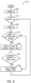
- FIG. 7 shows an example of a process 62 for controlling operation of the sump pump 4 in accordance with some embodiments of the invention. Specifically, process 62 can control and monitor the sump pump 4 in view of overcurrent conditions.
- Process 62 is shown to include turning on the pump (e.g., sump pump 4) at process block 64. Next, process 62 determines if the pump is on and if the motor is operating at its service factor load (service factor amps - SFA), at decision block 66. If the pump is on and if the motor is operating at its service factor load (i.e., the output of decision block 66 is "Yes"), then process 62 is shown to include determining if the pump has been on for a period of time greater than "X" seconds (decision block 68). In some embodiments, "X" can be any predefined time value.
- process 62 is shown to include determining if the motor current is greater than an over current value (decision block 70). If the motor current is not greater than an over current value (i.e., the output of decision block 70 is "No"), then the over current counter can be reset to zero (process block 80). Alternatively, if the motor current is greater than an over current value (i.e., the output of decision block 70 is "Yes"), then the over current counter can be incremented (process block 72).
- Process 86 is shown to further include determining if the over current counter value is greater than "X.” In some embodiments, "X" can be any predefined count value. If the over current counter is greater than "X" (i.e., the output of decision block 98 is "Yes"), then the locked rotor fault status can be set (process block 100). Subsequently, the pump can be turned off (process block 102). Process 86 is then shown to return to decision block 90.
- process 86 is shown to include determining if a command has been received to clear the fault (decision block 106).
- this command can come from the internet enabled device (e.g., the user device 58), as shown and described above, with respect to FIGS. 5-6 . If a command to clear the fault has been received (i.e., the output of decision block 106 is "Yes"), then the locked rotor fault status can be cleared (process block 108). Subsequently, process 86 can return to process block 88, and the pump can be turned on.
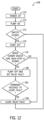
- FIG. 12 shows an example of a process 168 for controlling operation of the sump pump 4 in accordance with some embodiments of the invention. Specifically, process 168 can control and monitor the sump pump 4 in view of relay operation.
- process 168 can include providing power to the power adapter (e.g., power adapter 34) at process block 170.
- the sump pump is turned on at process block 172.
- Process 168 is shown to include determining if the switch/relay is closed (e.g., NO relay 14) at decision block 174. If the relay is closed, then the pump can be turned off at process block 176.
- process 168 is shown to include determining if the motor current is greater than 300mA after ten seconds at decision block 178. In some embodiments, these current and time threshold values can be different. If the motor current is not greater than 300mA after ten seconds, then the relay fault can be cleared.
- process 168 is shown to include determining if a command to clear the fault has been received at decision block 182. If a command to clear the fault has been received, then the relay fault can be cleared at process block 184. Process 168 can then again determine the position of the relay.
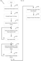
- FIG. 13 shows an example of a process 186 for controlling operation of the sump pump 4 in accordance with some embodiments of the invention. Specifically, process 186 can control and monitor the sump pump 4 in view of pump faults.
- process 214 can include providing power at process block 216.
- process 214 determines if the relay is closed at decision block 218. If the relay is closed, then process 214 is shown to include determining if the second switch is closed at decision block 220. If the second switch is open, then the high water fault can be cleared. If the second switch is closed, then the high water fault can be set at process block 222.
- Process 214 is shown to include determining if a command has been received to clear the fault at decision block 224. If a command to clear the fault has been received, then the high water fault can be cleared at process block 226. Process 214 can then again determine the position of the relay.
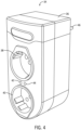
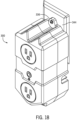
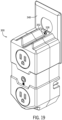
- the power adapter 300 can include at least a portion of the components included in the power adapter 34 described above, as well as perform at least a portion of the functions and/or processes that the power adapter 34 can perform as described above.
- the power adapter 300 includes a housing 304 configured to support and contain a printed circuit board (PCB).
- the PCB is electrically coupled to an integrated chip (e.g., integrated chip 52 described above).
- the PCB and integrated chip can be referred to as a controller.
- the power adapter 300 is described as including the integrated chip, this is merely an example, and any suitable type of hardware processor or combination of hardware processors can be used to monitor and/or control the sump pump 4 and the float switch 6.
- the integrated chip and PCB can be coupled to one or more sensors contained within the housing 304 and configured to monitor operation of the pump 4, such as a current sensor configured to sense an amount of power supplied to the pump 4.
- the integrated chip can be placed in communication with a user device such as the user device 58.
- the power adapter 300 includes a pump receptacle 308 configured to accept the power plug 8.
- the pump receptacle 308 can include three terminals for an AC pump. Insertion of the power plug 8 into the pump receptacle 38 can provide electrical power to the sump pump 4, as well as place the sump pump 4 in electrical communication with the interior PCB.
- the power adapter 300 includes a switch receptacle 312 configured to accept the power plug 10.
- the switch receptacle 312 can include three terminals. Insertion of the power plug 10 into the switch receptacle 312 can provide electrical power to the piggy-back float switch 6, as well as place the piggy-back float switch 6 in electrical communication with the interior PCB.
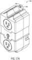
- the housing 300 can include a mounting hole 328 configured to allow a user to attach the power adapter 300 to a wall outlet. More specifically, the mounting hole 328 can be sized and positioned and oriented to allow a user to insert a screw 352 into a duplex wall outlet (not shown) covered by a cover plate 348.
- the duplex wall outlet includes two receptacles. The screw 352 can be inserted through the mounting hole 328 and the cover plate 348 and screwed into threads included in the duplex wall outlet. The screw 352 can then hold the power adapter 300 and the cover plate 348 securely to the duplex wall outlet.
- a tab extension 336 can be used with a screw 340 to attach the power adapter 300 to a simplex wall outlet (not shown) covered by a cover plate 344.
- the simplex outlet includes a single receptacle.
- the tab extension 336 can be inserted into the mounting hole 328 and the screw 340 can be inserted through a secondary mounting hole in the tab extension 336 in order to fasten the power adapter 300 and the cover plate 344 to the simplex wall outlet.
- the secondary mounting hole can be oriented to accept the screw 340 for insertion into the simplex wall outlet to affix the power adapter 300 to the simplex wall outlet.
- the tab extension 336 and the mounting hole 328 provide a durable and cost effective method to securely fasten the power adapter 300 to either a simplex or duplex wall outlet.
- the process 400 can proceed to 418. If the process 400 determined that the float switch 6 is not off (e.g., "NO” at 416), the process 400 can proceed to 414.
- the process 400 determines whether or not the current is below a predetermined threshold value.
- a predetermined threshold value can correspond to the current used by the pump when running but not pumping water (e.g., running dry). In this way, the process 400 can determine when the pump 4 is actually done evacuating out water. The process 400 can then proceed to 420.
- the process 400 can proceed to 424. If the process 400 determined that current is not below the predetermined threshold value (e.g., "NO” at 420), the process 400 can proceed to 418.
- the predetermined threshold value e.g., "YES” at 420
- the process 500 determines that the float switch 6 is off (e.g., "YES” at 516) if the process 500 determined that the float switch 6 is off (e.g., "YES” at 516), the process 500 proceeds to 520. If the process 500 determined that the float switch 6 is not off (e.g., "NO” at 516), the process 500 proceeds to 518.
- the process 500 continues supplying power to the pump 4.
- the process 500 can then proceed to 512.
- the process 500 can continue supplying power to the pump 4 until an amount of time equal to the time value has passed since the determining that the float switch 6 is off at step 516.
- the time value is determined previously using the process 400.
- the process 500 can start a countdown timer initialized with the time value at 516 and determine the amount of time equal to the time value has passed when the countdown timer expires. The process 500 can then proceed to 524.
- the results of the test can be provided to the homeowner (e.g., via a smartphone).
- the health test can be performed on an automated schedule, and/or when the homeowner requests a new health test.
- the power adapter e.g. power adapter 34 and/or 300
- the power adapter can measure operational values such as, but not limited to: instantaneous motor current, peak motor current, cycle time, number of cycles, pump run time, power factor, and/or voltage.
- analytics can provide values such as, but not limited to: average weekly motor current, average motor current per cycle, longest cycle length, shortest cycle length, total number of cycles, total pump run time, average power per week, and/or average power per cycle.
- a user/homeowner can provide inputs via an internet enabled device (e.g., their smartphone), such as but not limited to: clear fault, default settings, dry run delay time, dry run detection time, dry run enable/disable, excessive run time limit, fault readings, pump control method, pump start/stop, motor service factor amps, pump status, and power.
- a controller included in the power adapter e.g., the power adapter 34 and/or 300
- the process 600 can receive a request for performing the health test from a user or an monitoring process.
- the monitoring process can be used to monitor the power adaptor and can be run as an automated process on a server located remotely from the power adapter.
- the monitoring process may regularly (e.g., on a scheduled basis) perform health tests.
- the monitoring process can request the health test to be performed at variable intervals. For example, the monitoring process can increase the time between subsequent health tests, i.e. one month between a first health test and a second health test, two months between the second health test and a third health test, etc.
- the process 600 can then proceed to 608.
- the process 600 can run the pump 4 for a predetermined time period.
- the time period can be long enough to take sufficient operational data in order to assess how well the pump 4 is running.
- the operational data can be generated by sensors onboard the power adapter.
- the process 600 can then proceed to 612.
- the process 600 can receive operational data from the power adapter.
- the operational data can include average weekly motor current, average motor current per cycle, longest cycle length, shortest cycle length, total number of cycles, total pump run time, average power per week, average power per cycle, power factor, cycles between the last health test, the time of one or more health tests, voltage, and/or other operational parameters measured by the power adapter.
- the operational data can also include data derived during step 608 such as power factor, current drawn, and/or voltage.
- the process 600 can then proceed to 616.
- the process 600 can generate a health test report based on the operational data received at 612.
- the health test report can include one or more graphs or charts indicating the results of the test.
- Raw data e.g., unformatted numbers
- the report can include recommendation to help a user better run the pump 4 and/or maintenance that may need to be performed on the pump.
- the report can also include dealer information about one or more dealers closest to the location of the user so that the user can obtain parts and/or service for the pump 4.
- the process 600 can then proceed to 620.
- the process 600 can output the health test report to the user device. The process 600 can then end.
Landscapes
- Engineering & Computer Science (AREA)
- General Engineering & Computer Science (AREA)
- Theoretical Computer Science (AREA)
- Physics & Mathematics (AREA)
- General Physics & Mathematics (AREA)
- Mechanical Engineering (AREA)
- Computer Networks & Wireless Communication (AREA)
- Signal Processing (AREA)
- Computer Hardware Design (AREA)
- Remote Monitoring And Control Of Power-Distribution Networks (AREA)
- Control Of Non-Positive-Displacement Pumps (AREA)
- Control Of Positive-Displacement Pumps (AREA)
Claims (10)
- Système destiné à surveiller le fonctionnement d'une pompe de vidange (4) par l'intermédiaire d'un serveur distant, le système comprenant :
un adaptateur d'alimentation (34, 300), comprenant :un boîtier (36, 304) ;un dispositif de commande positionné à l'intérieur du boîtier et configuré pour exécuter des instructions lisibles par ordinateur, le dispositif de commande étant configuré pour établir une communication avec le serveur distant par l'intermédiaire d'une première connexion sans fil à un premier réseau sans fil ;des broches s'étendant à l'opposé du boîtier et en communication électrique avec des composants couplés au dispositif de commande, les broches étant configurées pour recevoir une alimentation électrique en provenance d'entrées d'alimentation électrique ;un premier réceptacle (38) positionné sur le boîtier et configuré pour accepter une entrée de commutateur à flotteur et connecter électriquement l'entrée de commutateur à flotteur au dispositif de commande et aux entrées d'alimentation électrique ; etun second réceptacle (40) positionné sur le boîtier et configuré pour accepter une entrée de pompe de vidange de la pompe de vidange et connecter électriquement l'entrée de pompe de vidange au dispositif de commande et aux entrées d'alimentation électrique,le dispositif de commande étant configuré pour exécuter les instructions lisibles par ordinateur de manière à :(i) déterminer qu'un commutateur à flotteur (6) électriquement couplé à l'adaptateur d'alimentation au niveau du premier réceptacle est sous tension ;(ii) fournir une alimentation à la pompe de vidange ;(iii) détecter un courant fourni à la pompe de vidange ;(iv) déterminer que le commutateur à flotteur est hors tension ;(v) déterminer que le courant est inférieur à une valeur seuil ;(vi) déterminer une valeur de temps qui s'est écoulée entre la détermination que le commutateur à flotteur est hors tension et la détermination que le courant est inférieur à la valeur seuil ; et(vii) commander la pompe de vidange sur la base de la valeur de temps ;et dans lequel, pour commander la pompe de vidange sur la base de la valeur de temps, le dispositif de commande est configuré pour réaliser un procédé comprenant :(a) déterminer que le commutateur à flotteur est sous tension ;(b) fournir une alimentation à la pompe de vidange ;(c) déterminer que le commutateur à flotteur est hors tension ;(d) continuer à fournir une alimentation à la pompe de vidange pendant une période de temps égale à la valeur de temps qui a passé depuis la détermination que le commutateur à flotteur est hors tension à l'étape (c) ; et(e) cesser de fournir une alimentation à la pompe de vidange. - Système selon la revendication 1, dans lequel le boîtier comprend un trou de montage (328) orienté pour accepter une vis (352) destinée à être insérée dans une prise murale duplex de manière à fixer l'adaptateur d'alimentation à la prise duplex.
- Système selon la revendication 2 comprenant en outre une extension de languette (336) comprenant un second trou de montage et étant configurée pour être insérée dans le trou de montage, le second trou de montage étant configuré pour accepter une vis destinée à être insérée dans une prise murale simplex de manière à fixer l'adaptateur d'alimentation à la prise simplex.
- Système selon la revendication 1, la revendication 2 ou la revendication 3, dans lequel l'adaptateur d'alimentation comprend en outre une borne comprenant deux contacteurs configurés pour se coupler à un détecteur de niveau d'eau élevé.
- Système selon la revendication 1, ou selon l'une quelconque des revendications 2 à 4, dans lequel le second réceptacle comprend trois bornes.
- Système selon la revendication 1, ou selon l'une quelconque des revendications 2 à 5, dans lequel l'adaptateur d'alimentation est configuré pour communiquer avec un dispositif d'utilisateur et recevoir une demande pour un test d'état fonctionnel en provenance du dispositif d'utilisateur.
- Système selon la revendication 1, ou selon l'une quelconque des revendications 2 à 6, dans lequel l'adaptateur d'alimentation comprend en outre :un indicateur lumineux (42, 44, 324) positionné sur une face avant de l'adaptateur d'alimentation ; et un bouton poussoir positionné sur la face avant de l'adaptateur d'alimentation,et dans lequel le bouton poussoir est configuré pour activer un mode local de l'adaptateur d'alimentation.
- Système selon la revendication 1, ou selon l'une quelconque des revendications 2 à 7, dans lequel le dispositif de commande est en outre configuré pour exécuter des instructions lisibles par ordinateur de manière à transmettre un message au serveur distant sur le premier réseau sans fil ;dans lequel le dispositif de commande inclut une carte de circuit imprimé et une puce intégrée (52),dans lequel l'entrée de commutateur à flotteur est en communication électrique avec la carte de circuit imprimé lors de son insertion dans le premier réceptacle, etdans lequel l'entrée de pompe de vidange est en communication électrique avec la carte de circuit imprimé lors de son insertion dans le second réceptacle.
- Système selon la revendication 8, dans lequel le message comprend au moins un ou une d'un courant de moteur hebdomadaire moyen, d'un courant de moteur moyen par cycle, d'une longueur de cycle la plus longue, d'une longueur de cycle la plus courte, d'un nombre total de cycles, d'un temps de fonctionnement de pompe total, d'une puissance moyenne par semaine, d'une puissance moyenne par cycle, d'un facteur de puissance, d'un nombre de cycles depuis un test d'état fonctionnel antérieur, d'un temps d'un ou de plusieurs tests d'état fonctionnel, et d'une tension mesurée par l'adaptateur d'alimentation.
- Procédé de commande et de surveillance d'une pompe de vidange (4) couplée à un adaptateur d'alimentation (34, 300), le procédé comprenant les étapes consistant à :(i) déterminer qu'un commutateur à flotteur est sous tension, le commutateur à flotteur étant couplé à l'adaptateur d'alimentation ;(ii) fournir une alimentation à la pompe de vidange ;(iii) détecter un courant fourni à la pompe de vidange ;(iv) déterminer que le commutateur à flotteur est hors tension ;(v) déterminer que le courant est inférieur à une valeur seuil ;(vi) déterminer une valeur de temps qui s'est écoulée entre la détermination que le commutateur à flotteur est hors tension à l'étape (iv) et la détermination que le courant est inférieur à la valeur seuil à l'étape (v) ;(vii) fournir une alimentation à la pompe de vidange sur la base de la valeur de temps ;et dans lequel la fourniture d'une alimentation à la pompe de vidange sur la base de la valeur de temps à l'étape (vii) comprend :(a) déterminer que le commutateur à flotteur est sous tension ;(b) fournir une alimentation à la pompe de vidange ;(c) déterminer que le commutateur à flotteur est hors tension ;(d) continuer à fournir une alimentation à la pompe de vidange pendant une période de temps égale à une valeur de temps prédéterminée qui a passé depuis la détermination que le commutateur à flotteur est hors tension à l'étape (c) ; et(e) cesser de fournir une alimentation à la pompe de vidange.
Applications Claiming Priority (1)
| Application Number | Priority Date | Filing Date | Title |
|---|---|---|---|
| US201862753560P | 2018-10-31 | 2018-10-31 |
Publications (2)
| Publication Number | Publication Date |
|---|---|
| EP3693607A1 EP3693607A1 (fr) | 2020-08-12 |
| EP3693607B1 true EP3693607B1 (fr) | 2025-07-02 |
Family
ID=68387169
Family Applications (1)
| Application Number | Title | Priority Date | Filing Date |
|---|---|---|---|
| EP19205740.4A Active EP3693607B1 (fr) | 2018-10-31 | 2019-10-28 | Systèmes et procédés pour une pompe de vidange connectée |
Country Status (2)
| Country | Link |
|---|---|
| US (4) | US11425786B2 (fr) |
| EP (1) | EP3693607B1 (fr) |
Families Citing this family (4)
| Publication number | Priority date | Publication date | Assignee | Title |
|---|---|---|---|---|
| EP3693607B1 (fr) | 2018-10-31 | 2025-07-02 | Pentair Flow Technologies, LLC | Systèmes et procédés pour une pompe de vidange connectée |
| CA3145525A1 (fr) * | 2019-06-28 | 2020-12-30 | Dni Realty, Llc | Systemes et procedes de commande de puisard de sous-sol |
| USD965538S1 (en) * | 2019-10-28 | 2022-10-04 | Pentair Flow Technologies, Llc | Sump pump controller |
| US12378758B2 (en) * | 2021-02-23 | 2025-08-05 | Alderon Industries, Llc | Septic system including control and monitoring system |
Family Cites Families (75)
| Publication number | Priority date | Publication date | Assignee | Title |
|---|---|---|---|---|
| US2687693A (en) | 1949-12-27 | 1954-08-31 | Tokheim Corp | Sump pump |
| US4222711A (en) | 1978-06-22 | 1980-09-16 | I2 Ds | Sump pump control system |
| US4187503A (en) | 1978-09-05 | 1980-02-05 | Walton Robert G | Sump alarm device |
| US4255747A (en) | 1978-11-15 | 1981-03-10 | Bunia Roderick J | Sump pump level warning device |
| US4369438A (en) | 1980-05-13 | 1983-01-18 | Wilhelmi Joseph R | Sump pump detection and alarm system |
| US4456432A (en) | 1980-10-27 | 1984-06-26 | Jennings Pump Company | Emergency sump pump and alarm warning system |
| CA1218445A (fr) | 1983-12-05 | 1987-02-24 | Richard C. Doyle | Protection contre les chocs electriques |
| US5324170A (en) | 1984-12-31 | 1994-06-28 | Rule Industries, Inc. | Pump control apparatus and method |
| US5015151A (en) | 1989-08-21 | 1991-05-14 | Shell Oil Company | Motor controller for electrical submersible pumps |
| US6462666B1 (en) * | 1995-05-03 | 2002-10-08 | Virgil A. Einck | Housing and electric connection panel for sump pump and full septic tank alarm |
| US5672050A (en) | 1995-08-04 | 1997-09-30 | Lynx Electronics, Inc. | Apparatus and method for monitoring a sump pump |
| US6676382B2 (en) | 1999-11-19 | 2004-01-13 | Campbell Hausfeld/Scott Fetzer Company | Sump pump monitoring and control system |
| US6375430B1 (en) | 2000-05-03 | 2002-04-23 | Campbell Hausfeld/Scott Fetzer Company | Sump pump alarm |
| ITMI20030313A1 (it) | 2003-02-21 | 2004-08-22 | Tm P S P A Termomeccanica Pompe | Sistema per il monitaraggio remoto di macchine centrifughe. |
| US7309216B1 (en) | 2004-01-23 | 2007-12-18 | Spadola Jr Joseph | Pump control and management system |
| US7458782B1 (en) | 2004-01-23 | 2008-12-02 | Spadola Jr Joseph | Computer monitoring system for pumps |
| US20060008355A1 (en) | 2004-07-07 | 2006-01-12 | Low Douglas A | Bilge pump monitor with flow detection |
| US20060078435A1 (en) | 2004-08-19 | 2006-04-13 | Metropolitan Industries | Pump monitoring system |
| US7429842B2 (en) | 2005-02-04 | 2008-09-30 | Alan M. Schulman | Control and alarm system for sump pump |
| US7307538B2 (en) | 2005-04-06 | 2007-12-11 | Metropolitan Industries, Inc. | Pump connector system |
| US20080031752A1 (en) | 2006-03-03 | 2008-02-07 | Littwin Kenneth M | Sump pump control system |
| US20080031751A1 (en) | 2006-03-03 | 2008-02-07 | Littwin Kenneth M | Sump pump control system |
| US20070258827A1 (en) | 2006-05-02 | 2007-11-08 | Daniel Gierke | Sump pump system |
| US8297937B2 (en) | 2006-06-12 | 2012-10-30 | Stak Enterprises, Inc. | Pump control apparatus, system and method |
| US7498910B2 (en) | 2006-07-28 | 2009-03-03 | Cooper Technologies Company | Ground fault circuit interrupter device |
| US7876539B2 (en) * | 2006-10-23 | 2011-01-25 | Pentair Pump Group, Inc. | Electrical apparatus with current dampening device |
| US8380355B2 (en) | 2007-03-19 | 2013-02-19 | Wayne/Scott Fetzer Company | Capacitive sensor and method and apparatus for controlling a pump using same |
| US8047805B2 (en) | 2007-08-31 | 2011-11-01 | Bourell Jr Alfred M | Solid state sump pump control |
| US8579600B2 (en) | 2008-03-28 | 2013-11-12 | Sta-Rite Industries, Llc | System and method for portable battery back-up sump pump |
| GB2460301A (en) | 2008-05-30 | 2009-12-02 | Pulsar Process Measurement Ltd | Sump monitoring method and apparatus |
| US8622713B2 (en) | 2008-12-29 | 2014-01-07 | Little Giant Pump Company | Method and apparatus for detecting the fluid condition in a pump |
| US8500412B2 (en) | 2009-10-08 | 2013-08-06 | Liberty Pumps, Inc. | Alarm system for a sump pump assembly |
| US8956130B2 (en) * | 2009-12-23 | 2015-02-17 | Pentair Flow Technologies, Llc | Redundant sump pump system |
| WO2011106557A1 (fr) | 2010-02-25 | 2011-09-01 | Hayward Industries, Inc. | Unité de commande de pompe possédant une capacité de commande de dispositif extérieur |
| US9958878B2 (en) * | 2010-05-07 | 2018-05-01 | Metropolitan Industries, Inc. | Multi-priority pump control unit |
| US8907789B2 (en) * | 2010-05-07 | 2014-12-09 | Metropolitan Industries, Inc. | Pump control unit |
| US20110311370A1 (en) | 2010-06-17 | 2011-12-22 | Sloss Jeffrey A | Sump pump system with remote control and monitoring |
| CA2808939C (fr) | 2012-05-04 | 2019-12-03 | Sulzer Pump Solutions Ab | Systeme de pompe |
| US9638193B2 (en) | 2012-10-25 | 2017-05-02 | Pentair Flow Technologies, Llc | Sump pump remote monitoring systems and methods |
| US9441625B2 (en) | 2013-01-11 | 2016-09-13 | Mary Ann Schoendorff | System and method for pump component controlling and testing |
| US9157434B2 (en) | 2013-01-22 | 2015-10-13 | PumpSpy Technology, LLC | Sump pump system with automated system monitoring and data collection |
| US11008738B2 (en) | 2013-08-07 | 2021-05-18 | Metropolitan Industries, Inc. | Pump control system having temperature detection and interface for remote monitoring and control |
| US9528520B2 (en) | 2013-11-26 | 2016-12-27 | Beacon Technical Systems, Llc | Test and monitoring system for a dual sump pump system |
| US9528512B2 (en) | 2013-11-26 | 2016-12-27 | Beacon Technical Systems, Llc | Test and monitoring system for a battery-powered DC pump installation |
| US9528873B2 (en) | 2013-11-26 | 2016-12-27 | Beacon Technical Systems, Llc | Test and monitoring system for a sump pump installation having a self-monitoring liquid level sensing module |
| US9528522B2 (en) | 2013-11-26 | 2016-12-27 | Beacon Technical Systems, Llc | Test and monitoring system for a sump pump installation having a self-monitoring valve module for admitting water to the sump pit |
| US9525309B2 (en) | 2013-11-26 | 2016-12-20 | Beacon Technical Systems, Llc | Battery-powered backup power system for a sump pump installation |
| US9523366B2 (en) | 2013-11-26 | 2016-12-20 | Beacon Technical Systems, Llc | Test and monitoring system for a sump pump installation having a self-protecting valve assembly for admitting water to the sump container |
| US9534593B2 (en) | 2013-11-26 | 2017-01-03 | Beacon Technical Systems, Llc | Test and monitoring system for a sump pump installation operable from a remote location |
| US9534606B2 (en) | 2013-11-26 | 2017-01-03 | Beacon Technical Systems, Llc | Test and monitoring system for a sump pump installation including trend analysis of pump performance |
| US9500193B2 (en) | 2014-02-24 | 2016-11-22 | Sears Brand, L.L.C. | Sump pump monitoring device and method |
| US9500194B2 (en) * | 2014-04-15 | 2016-11-22 | Sears Brands, L.L.C. | Sump pump monitoring device and method |
| US8892263B1 (en) | 2014-05-19 | 2014-11-18 | State Farm Mutual Automobile Insurance Company | Systems and methods for detecting and resolving sump pump failures |
| US9696360B2 (en) | 2014-06-04 | 2017-07-04 | Rf Group Llc | Sump/ejector pump monitor and sump/ejector pump failure warning system |
| WO2015195520A1 (fr) | 2014-06-16 | 2015-12-23 | Schlumberger Canada Limited | Détection de défauts dans des pompes submersibles électriques |
| US20160284496A1 (en) | 2015-03-25 | 2016-09-29 | Reza Afshar | Current sensing switch for use with pumps |
| EP3274546A4 (fr) | 2015-03-25 | 2018-10-03 | Ge Oil & Gas Esp, Inc. | Système et procédé de surveillance d'état en temps réel d'un système de pompage submersible électrique |
| US10626873B2 (en) | 2015-05-12 | 2020-04-21 | Connectm Technology Solutions, Inc. | System and method for determining a use condition for an appliance |
| US20170170979A1 (en) * | 2015-12-15 | 2017-06-15 | Pentair Flow Technologies, Llc | Systems and Methods for Wireless Control and Monitoring of Residential Devices |
| US10711788B2 (en) * | 2015-12-17 | 2020-07-14 | Wayne/Scott Fetzer Company | Integrated sump pump controller with status notifications |
| US20170218943A1 (en) | 2016-01-29 | 2017-08-03 | Ramparts, Llc | Controller for pump system |
| US10208747B2 (en) | 2016-02-09 | 2019-02-19 | Beacon Technical Systems, Llc | Trap for pump testing and monitoring systems |
| US10323647B2 (en) | 2016-06-28 | 2019-06-18 | Stancor, L.P. | Self-test methods and systems for submersible pump systems |
| US10585011B2 (en) | 2016-07-15 | 2020-03-10 | Sumptracker, Llc | Sump pump tracking device |
| US10865787B2 (en) | 2016-12-06 | 2020-12-15 | Pentair Flow Technologies, Llc | Connected pump system controller and method of use |
| CA3047090A1 (fr) | 2016-12-13 | 2018-06-21 | Wayne/Scott Fetzer Company | Module de communication de pompe, systeme de pompe et procedes associes a ceux-ci |
| US10364816B2 (en) | 2017-01-25 | 2019-07-30 | Lincus, Inc. | Remote pump managing device |
| US11187223B2 (en) | 2017-04-10 | 2021-11-30 | Logical Concepts, Inc. | Home flood prevention appliance system |
| CA3018882A1 (fr) | 2017-09-29 | 2019-03-29 | Elexa Consumer Products, Inc. | Moniteur de pompe submersible |
| US11035367B1 (en) | 2018-03-01 | 2021-06-15 | Flint & Walling, Inc. | Sump pump system with an electronic controller module secured in a sump pump power cord |
| EP3693607B1 (fr) | 2018-10-31 | 2025-07-02 | Pentair Flow Technologies, LLC | Systèmes et procédés pour une pompe de vidange connectée |
| US12129846B2 (en) | 2020-07-24 | 2024-10-29 | Pulsafeeder, Inc. | Method and system for operating a pump |
| US11859608B2 (en) | 2020-10-26 | 2024-01-02 | Masterflex, Llc | Fluid resistant display apparatus |
| US12012953B2 (en) | 2020-11-02 | 2024-06-18 | Masterflex, Llc | Liquid resistant pump, pump housing, and controls and methods of making and use thereof |
| US11174857B1 (en) | 2020-11-25 | 2021-11-16 | General Air Products, Inc. | Digital pressure switch systems and methods |
-
2019
- 2019-10-28 EP EP19205740.4A patent/EP3693607B1/fr active Active
- 2019-10-28 US US16/666,260 patent/US11425786B2/en active Active
-
2022
- 2022-08-23 US US17/821,718 patent/US11838992B2/en active Active
-
2023
- 2023-10-12 US US18/485,728 patent/US12219664B2/en active Active
-
2025
- 2025-02-04 US US19/044,925 patent/US20250185123A1/en active Pending
Also Published As
| Publication number | Publication date |
|---|---|
| US11838992B2 (en) | 2023-12-05 |
| EP3693607A1 (fr) | 2020-08-12 |
| US11425786B2 (en) | 2022-08-23 |
| US20200137830A1 (en) | 2020-04-30 |
| US20250185123A1 (en) | 2025-06-05 |
| US20240040665A1 (en) | 2024-02-01 |
| US20220418040A1 (en) | 2022-12-29 |
| US12219664B2 (en) | 2025-02-04 |
Similar Documents
| Publication | Publication Date | Title |
|---|---|---|
| US12219664B2 (en) | Systems and methods for a connected sump pump | |
| US20210102534A1 (en) | Connected pump system controller and method of use | |
| US10274945B2 (en) | HVAC system remote monitoring and diagnosis | |
| US9441625B2 (en) | System and method for pump component controlling and testing | |
| US9551504B2 (en) | HVAC system remote monitoring and diagnosis | |
| US9500193B2 (en) | Sump pump monitoring device and method | |
| US9500194B2 (en) | Sump pump monitoring device and method | |
| JP7515455B2 (ja) | 井戸管理システム | |
| WO2015044790A2 (fr) | Prise murale intelligente | |
| EP3214382A1 (fr) | Procédé et dispositif de commande de drainage d'un déshumidificateur et déshumidificateur | |
| US20250116276A1 (en) | Well management system | |
| CN106549365B (zh) | 用电安全检测防护方法及系统 | |
| CA3107265C (fr) | Systeme de gestion du puits | |
| CN114779709A (zh) | 家电设备的监测方法、装置、可读存储介质和家电设备 |
Legal Events
| Date | Code | Title | Description |
|---|---|---|---|
| PUAI | Public reference made under article 153(3) epc to a published international application that has entered the european phase |
Free format text: ORIGINAL CODE: 0009012 |
|
| STAA | Information on the status of an ep patent application or granted ep patent |
Free format text: STATUS: THE APPLICATION HAS BEEN PUBLISHED |
|
| AK | Designated contracting states |
Kind code of ref document: A1 Designated state(s): AL AT BE BG CH CY CZ DE DK EE ES FI FR GB GR HR HU IE IS IT LI LT LU LV MC MK MT NL NO PL PT RO RS SE SI SK SM TR |
|
| AX | Request for extension of the european patent |
Extension state: BA ME |
|
| STAA | Information on the status of an ep patent application or granted ep patent |
Free format text: STATUS: REQUEST FOR EXAMINATION WAS MADE |
|
| 17P | Request for examination filed |
Effective date: 20210212 |
|
| RBV | Designated contracting states (corrected) |
Designated state(s): AL AT BE BG CH CY CZ DE DK EE ES FI FR GB GR HR HU IE IS IT LI LT LU LV MC MK MT NL NO PL PT RO RS SE SI SK SM TR |
|
| STAA | Information on the status of an ep patent application or granted ep patent |
Free format text: STATUS: EXAMINATION IS IN PROGRESS |
|
| 17Q | First examination report despatched |
Effective date: 20220801 |
|
| GRAP | Despatch of communication of intention to grant a patent |
Free format text: ORIGINAL CODE: EPIDOSNIGR1 |
|
| STAA | Information on the status of an ep patent application or granted ep patent |
Free format text: STATUS: GRANT OF PATENT IS INTENDED |
|
| INTG | Intention to grant announced |
Effective date: 20240819 |
|
| GRAJ | Information related to disapproval of communication of intention to grant by the applicant or resumption of examination proceedings by the epo deleted |
Free format text: ORIGINAL CODE: EPIDOSDIGR1 |
|
| STAA | Information on the status of an ep patent application or granted ep patent |
Free format text: STATUS: EXAMINATION IS IN PROGRESS |
|
| GRAP | Despatch of communication of intention to grant a patent |
Free format text: ORIGINAL CODE: EPIDOSNIGR1 |
|
| INTC | Intention to grant announced (deleted) | ||
| STAA | Information on the status of an ep patent application or granted ep patent |
Free format text: STATUS: GRANT OF PATENT IS INTENDED |
|
| INTG | Intention to grant announced |
Effective date: 20250130 |
|
| GRAS | Grant fee paid |
Free format text: ORIGINAL CODE: EPIDOSNIGR3 |
|
| GRAA | (expected) grant |
Free format text: ORIGINAL CODE: 0009210 |
|
| STAA | Information on the status of an ep patent application or granted ep patent |
Free format text: STATUS: THE PATENT HAS BEEN GRANTED |
|
| RAP3 | Party data changed (applicant data changed or rights of an application transferred) |
Owner name: PENTAIR FLOW TECHNOLOGIES, LLC |
|
| AK | Designated contracting states |
Kind code of ref document: B1 Designated state(s): AL AT BE BG CH CY CZ DE DK EE ES FI FR GB GR HR HU IE IS IT LI LT LU LV MC MK MT NL NO PL PT RO RS SE SI SK SM TR |
|
| REG | Reference to a national code |
Ref country code: GB Ref legal event code: FG4D |
|
| REG | Reference to a national code |
Ref country code: CH Ref legal event code: EP |
|
| REG | Reference to a national code |
Ref country code: DE Ref legal event code: R096 Ref document number: 602019071874 Country of ref document: DE |
|
| REG | Reference to a national code |
Ref country code: IE Ref legal event code: FG4D |
|
| P01 | Opt-out of the competence of the unified patent court (upc) registered |
Free format text: CASE NUMBER: UPC_APP_4032_3693607/2025 Effective date: 20250822 |
|
| REG | Reference to a national code |
Ref country code: NL Ref legal event code: MP Effective date: 20250702 |
|
| PG25 | Lapsed in a contracting state [announced via postgrant information from national office to epo] |
Ref country code: PT Free format text: LAPSE BECAUSE OF FAILURE TO SUBMIT A TRANSLATION OF THE DESCRIPTION OR TO PAY THE FEE WITHIN THE PRESCRIBED TIME-LIMIT Effective date: 20251103 |
|
| PG25 | Lapsed in a contracting state [announced via postgrant information from national office to epo] |
Ref country code: NL Free format text: LAPSE BECAUSE OF FAILURE TO SUBMIT A TRANSLATION OF THE DESCRIPTION OR TO PAY THE FEE WITHIN THE PRESCRIBED TIME-LIMIT Effective date: 20250702 |
|
| REG | Reference to a national code |
Ref country code: AT Ref legal event code: MK05 Ref document number: 1809502 Country of ref document: AT Kind code of ref document: T Effective date: 20250702 |
|
| PG25 | Lapsed in a contracting state [announced via postgrant information from national office to epo] |
Ref country code: IS Free format text: LAPSE BECAUSE OF FAILURE TO SUBMIT A TRANSLATION OF THE DESCRIPTION OR TO PAY THE FEE WITHIN THE PRESCRIBED TIME-LIMIT Effective date: 20251102 |
|
| PGFP | Annual fee paid to national office [announced via postgrant information from national office to epo] |
Ref country code: DE Payment date: 20251020 Year of fee payment: 7 |
|
| PGFP | Annual fee paid to national office [announced via postgrant information from national office to epo] |
Ref country code: GB Payment date: 20251024 Year of fee payment: 7 |
|
| PG25 | Lapsed in a contracting state [announced via postgrant information from national office to epo] |
Ref country code: NO Free format text: LAPSE BECAUSE OF FAILURE TO SUBMIT A TRANSLATION OF THE DESCRIPTION OR TO PAY THE FEE WITHIN THE PRESCRIBED TIME-LIMIT Effective date: 20251002 |
|
| REG | Reference to a national code |
Ref country code: LT Ref legal event code: MG9D |
|
| PG25 | Lapsed in a contracting state [announced via postgrant information from national office to epo] |
Ref country code: AT Free format text: LAPSE BECAUSE OF FAILURE TO SUBMIT A TRANSLATION OF THE DESCRIPTION OR TO PAY THE FEE WITHIN THE PRESCRIBED TIME-LIMIT Effective date: 20250702 |
|
| PG25 | Lapsed in a contracting state [announced via postgrant information from national office to epo] |
Ref country code: FI Free format text: LAPSE BECAUSE OF FAILURE TO SUBMIT A TRANSLATION OF THE DESCRIPTION OR TO PAY THE FEE WITHIN THE PRESCRIBED TIME-LIMIT Effective date: 20250702 |
|
| PG25 | Lapsed in a contracting state [announced via postgrant information from national office to epo] |
Ref country code: HR Free format text: LAPSE BECAUSE OF FAILURE TO SUBMIT A TRANSLATION OF THE DESCRIPTION OR TO PAY THE FEE WITHIN THE PRESCRIBED TIME-LIMIT Effective date: 20250702 |
|
| PGFP | Annual fee paid to national office [announced via postgrant information from national office to epo] |
Ref country code: FR Payment date: 20251024 Year of fee payment: 7 |
|
| PG25 | Lapsed in a contracting state [announced via postgrant information from national office to epo] |
Ref country code: GR Free format text: LAPSE BECAUSE OF FAILURE TO SUBMIT A TRANSLATION OF THE DESCRIPTION OR TO PAY THE FEE WITHIN THE PRESCRIBED TIME-LIMIT Effective date: 20251003 |
|
| PG25 | Lapsed in a contracting state [announced via postgrant information from national office to epo] |
Ref country code: SE Free format text: LAPSE BECAUSE OF FAILURE TO SUBMIT A TRANSLATION OF THE DESCRIPTION OR TO PAY THE FEE WITHIN THE PRESCRIBED TIME-LIMIT Effective date: 20250702 Ref country code: CZ Free format text: LAPSE BECAUSE OF FAILURE TO SUBMIT A TRANSLATION OF THE DESCRIPTION OR TO PAY THE FEE WITHIN THE PRESCRIBED TIME-LIMIT Effective date: 20250702 |
|
| PG25 | Lapsed in a contracting state [announced via postgrant information from national office to epo] |
Ref country code: LV Free format text: LAPSE BECAUSE OF FAILURE TO SUBMIT A TRANSLATION OF THE DESCRIPTION OR TO PAY THE FEE WITHIN THE PRESCRIBED TIME-LIMIT Effective date: 20250702 |
|
| PG25 | Lapsed in a contracting state [announced via postgrant information from national office to epo] |
Ref country code: BG Free format text: LAPSE BECAUSE OF FAILURE TO SUBMIT A TRANSLATION OF THE DESCRIPTION OR TO PAY THE FEE WITHIN THE PRESCRIBED TIME-LIMIT Effective date: 20250702 Ref country code: PL Free format text: LAPSE BECAUSE OF FAILURE TO SUBMIT A TRANSLATION OF THE DESCRIPTION OR TO PAY THE FEE WITHIN THE PRESCRIBED TIME-LIMIT Effective date: 20250702 |
|
| PG25 | Lapsed in a contracting state [announced via postgrant information from national office to epo] |
Ref country code: RS Free format text: LAPSE BECAUSE OF FAILURE TO SUBMIT A TRANSLATION OF THE DESCRIPTION OR TO PAY THE FEE WITHIN THE PRESCRIBED TIME-LIMIT Effective date: 20251002 |
|
| PG25 | Lapsed in a contracting state [announced via postgrant information from national office to epo] |
Ref country code: ES Free format text: LAPSE BECAUSE OF FAILURE TO SUBMIT A TRANSLATION OF THE DESCRIPTION OR TO PAY THE FEE WITHIN THE PRESCRIBED TIME-LIMIT Effective date: 20250702 |
|
| PG25 | Lapsed in a contracting state [announced via postgrant information from national office to epo] |
Ref country code: RO Free format text: LAPSE BECAUSE OF FAILURE TO SUBMIT A TRANSLATION OF THE DESCRIPTION OR TO PAY THE FEE WITHIN THE PRESCRIBED TIME-LIMIT Effective date: 20250702 |
|
| PG25 | Lapsed in a contracting state [announced via postgrant information from national office to epo] |
Ref country code: SM Free format text: LAPSE BECAUSE OF FAILURE TO SUBMIT A TRANSLATION OF THE DESCRIPTION OR TO PAY THE FEE WITHIN THE PRESCRIBED TIME-LIMIT Effective date: 20250702 |
|
| PG25 | Lapsed in a contracting state [announced via postgrant information from national office to epo] |
Ref country code: DK Free format text: LAPSE BECAUSE OF FAILURE TO SUBMIT A TRANSLATION OF THE DESCRIPTION OR TO PAY THE FEE WITHIN THE PRESCRIBED TIME-LIMIT Effective date: 20250702 |
|
| PG25 | Lapsed in a contracting state [announced via postgrant information from national office to epo] |
Ref country code: IT Free format text: LAPSE BECAUSE OF FAILURE TO SUBMIT A TRANSLATION OF THE DESCRIPTION OR TO PAY THE FEE WITHIN THE PRESCRIBED TIME-LIMIT Effective date: 20250702 |