EP3693708B1 - Cylindre doté d'une tige de piston et d'un dispositif optique de mesure de la position - Google Patents
Cylindre doté d'une tige de piston et d'un dispositif optique de mesure de la position Download PDFInfo
- Publication number
- EP3693708B1 EP3693708B1 EP19156224.8A EP19156224A EP3693708B1 EP 3693708 B1 EP3693708 B1 EP 3693708B1 EP 19156224 A EP19156224 A EP 19156224A EP 3693708 B1 EP3693708 B1 EP 3693708B1
- Authority
- EP
- European Patent Office
- Prior art keywords
- code
- piston rod
- code word
- cylinder
- characters
- Prior art date
- Legal status (The legal status is an assumption and is not a legal conclusion. Google has not performed a legal analysis and makes no representation as to the accuracy of the status listed.)
- Active
Links
Images


Classifications
-
- G—PHYSICS
- G01—MEASURING; TESTING
- G01D—MEASURING NOT SPECIALLY ADAPTED FOR A SPECIFIC VARIABLE; ARRANGEMENTS FOR MEASURING TWO OR MORE VARIABLES NOT COVERED IN A SINGLE OTHER SUBCLASS; TARIFF METERING APPARATUS; MEASURING OR TESTING NOT OTHERWISE PROVIDED FOR
- G01D5/00—Mechanical means for transferring the output of a sensing member; Means for converting the output of a sensing member to another variable where the form or nature of the sensing member does not constrain the means for converting; Transducers not specially adapted for a specific variable
- G01D5/26—Mechanical means for transferring the output of a sensing member; Means for converting the output of a sensing member to another variable where the form or nature of the sensing member does not constrain the means for converting; Transducers not specially adapted for a specific variable characterised by optical transfer means, i.e. using infrared, visible, or ultraviolet light
- G01D5/32—Mechanical means for transferring the output of a sensing member; Means for converting the output of a sensing member to another variable where the form or nature of the sensing member does not constrain the means for converting; Transducers not specially adapted for a specific variable characterised by optical transfer means, i.e. using infrared, visible, or ultraviolet light with attenuation or whole or partial obturation of beams of light
- G01D5/34—Mechanical means for transferring the output of a sensing member; Means for converting the output of a sensing member to another variable where the form or nature of the sensing member does not constrain the means for converting; Transducers not specially adapted for a specific variable characterised by optical transfer means, i.e. using infrared, visible, or ultraviolet light with attenuation or whole or partial obturation of beams of light the beams of light being detected by photocells
- G01D5/347—Mechanical means for transferring the output of a sensing member; Means for converting the output of a sensing member to another variable where the form or nature of the sensing member does not constrain the means for converting; Transducers not specially adapted for a specific variable characterised by optical transfer means, i.e. using infrared, visible, or ultraviolet light with attenuation or whole or partial obturation of beams of light the beams of light being detected by photocells using displacement encoding scales
- G01D5/34776—Absolute encoders with analogue or digital scales
- G01D5/34792—Absolute encoders with analogue or digital scales with only digital scales or both digital and incremental scales
-
- G—PHYSICS
- G01—MEASURING; TESTING
- G01D—MEASURING NOT SPECIALLY ADAPTED FOR A SPECIFIC VARIABLE; ARRANGEMENTS FOR MEASURING TWO OR MORE VARIABLES NOT COVERED IN A SINGLE OTHER SUBCLASS; TARIFF METERING APPARATUS; MEASURING OR TESTING NOT OTHERWISE PROVIDED FOR
- G01D5/00—Mechanical means for transferring the output of a sensing member; Means for converting the output of a sensing member to another variable where the form or nature of the sensing member does not constrain the means for converting; Transducers not specially adapted for a specific variable
- G01D5/26—Mechanical means for transferring the output of a sensing member; Means for converting the output of a sensing member to another variable where the form or nature of the sensing member does not constrain the means for converting; Transducers not specially adapted for a specific variable characterised by optical transfer means, i.e. using infrared, visible, or ultraviolet light
- G01D5/32—Mechanical means for transferring the output of a sensing member; Means for converting the output of a sensing member to another variable where the form or nature of the sensing member does not constrain the means for converting; Transducers not specially adapted for a specific variable characterised by optical transfer means, i.e. using infrared, visible, or ultraviolet light with attenuation or whole or partial obturation of beams of light
- G01D5/34—Mechanical means for transferring the output of a sensing member; Means for converting the output of a sensing member to another variable where the form or nature of the sensing member does not constrain the means for converting; Transducers not specially adapted for a specific variable characterised by optical transfer means, i.e. using infrared, visible, or ultraviolet light with attenuation or whole or partial obturation of beams of light the beams of light being detected by photocells
- G01D5/347—Mechanical means for transferring the output of a sensing member; Means for converting the output of a sensing member to another variable where the form or nature of the sensing member does not constrain the means for converting; Transducers not specially adapted for a specific variable characterised by optical transfer means, i.e. using infrared, visible, or ultraviolet light with attenuation or whole or partial obturation of beams of light the beams of light being detected by photocells using displacement encoding scales
- G01D5/34746—Linear encoders
Definitions
- the present invention relates to a cylinder with a piston rod and an optical position sensor which is directed at a marking arranged on the piston rod.
- a position measurement on the piston rod of a cylinder it is known to incrementally record the position of the piston rod starting from a reference mark.
- Such a marking is used by first recording the reference mark, whereby a starting position is known and, starting from the known starting position, the current position of the piston rod is incrementally determined via the further marking.
- Such a marking has the disadvantage that, depending on the position of the piston rod at the start of the measurement, a long reference run is sometimes required in order to record the reference mark as the starting point for the incremental measurement.
- Absolute measuring systems are also known, in which the marking on the piston rod has a code that indicates an absolute position of the marking on the piston rod.
- the disadvantage of coding the absolute position has been found to be that coding the position and setting up the sensor required for this is complex.
- a hydraulic, pneumatic or similar cylinder which has a piston rod provided with a marking, to which an optical sensor is directed.
- the marking provided on the piston rod allows both incremental and absolute coding of the position.
- Three reading heads are provided to determine the absolute position, two of which are arranged one behind the other in the direction of the marking and thus allow an evaluation of the speed.
- the third sensor measures independently from the first two sensors and allows the reading of an absolute position on the piston rod.
- a device for determining the position of a movable mechanical element is known, as is a method for producing such a code.
- code elements are provided which form a distinguishable part of an optically readable marking.
- the code consisting of several code elements forms a numerical value in binary digits (bits).
- the numerical value coded in this way indicates the position on the piston rod.
- a code element has a section with a predetermined width T on the surface of the piston rod. Two sections are provided for coding individual bits, with a distance of 1 T or 2 T each indicating the binary digit 0 or 1. Furthermore, end markings with a length of 4 T are provided which separate a pair of adjacent surfaces. For coding, pseudo-random binary sequences are used. The position is determined via the random coding with the help of a stored field.
- a position scale and an optical reading sensor for reading it have become known.
- a code with scale lines of two different widths is used, with a binary coding of the position.
- An individual code consists of a predetermined number of consecutive lines on the scale.
- a position detection system is known in which a group of markings determine a unique code that is used to determine the position.
- the marking consists of thinner and thicker lines, where the group of markings consists of 12 marks on the piston rod.
- a position scale consisting of lines having a first and a second edge, with either the first or the second edge being arranged at regular intervals.
- the lines have at least two different widths and consecutive lines on the scale form an individual code.
- the invention is based on the object of providing a marking for a cylinder with a piston rod which contains reliable and easy-to-read position information.
- the cylinder according to the invention has a piston rod and an optical position sensor which is directed at a marking arranged on the piston rod. If the piston rod of the cylinder is moved, the marking moves relative to the position sensor.
- the marking has at least two code elements which can be distinguished by the optical position sensor.
- the b different code symbols and the separator preferably each have a different physical length on the piston rod.
- several code characters (0, 1, 2, ..., n-1) form a code word from a predetermined number of n code characters.
- the separator can also be simple or composed of one or more characters in the sense of sub-separators.
- the invention is particularly characterized in that the marking extending over the piston rod has a large number of code word pairs from adjacent code words, which in pairs have a predetermined total physical length on the piston rod.
- the particular advantage of code word pairs with the same physical length on the piston rod is that when the position of the marking is read out, the code word pairs themselves can be used to check the signals read. If an error occurs during reading, it is known after which distance the reading process for a code word pair should have been completed and when a new reading process can be initiated.
- ternary coding a code word consists of a sequence of "0", "1" and "2".
- the code words (010) and (101) have a different physical length on the piston rod, since, for example, the "0" on the piston rod is encoded by a first sequence of code elements (dhdhh), while the “1” is encoded as another sequence of code elements (dhdhdhh) with a different physical length on the piston rod.
- “d” stands for dark and "h” for light.
- the character of the code elements "dd” or “hh” then stands for two code elements in a row, i.e. a coding with double physical Length on the piston rod.
- the code words have the same binary or logical length with three binary characters, but a completely different physical length on the piston rod.
- the "2" is also coded, for example by (dhdhdhdhh), so that the physical length on the piston rod is also varied.
- the code words in a code word pair are adjacent to each other on the piston rod.
- the two code words in a code word pair have a total of two separators. It has proven to be practical if each code word is followed or introduced by a separator. With this assignment, it then follows naturally that two separators are contained in a code word pair.
- each code word has a predetermined number of code characters that form the code word.
- the different lengths of the code words on the piston rod occur despite the fixed number of code characters in the code word because the code elements or the code characters formed from them have a different length on the piston rod. Even if the code elements have the same length on the piston rod, the physical length on the piston rod is not the same for the code characters.
- two code words separated from each other by separators each with n code characters, have a maximum distance (in the sense of a Hamming distance) from each other.
- Distance means the number and value of code characters that are converted into a code word. must be passed in order to get from a first code word to a second code word.
- the distance of n for two code words with n code symbols each means that in a binary representation the sum code word consists of n consecutive "1". In a ternary coding the distance is accordingly 2n and due to the distance the sum code word contains n consecutive "2".
- the code elements (h, d) are preferably formed from light and dark stripes on the piston rod, which means that on the one hand the transition from a light stripe h to a dark stripe d and from a dark stripe d to a light stripe h can be detected. On the other hand, two or more light or dark stripes can also be detected one after the other, for example from a scanning rate or a feed speed.
- the code elements made up of light and dark stripes are less susceptible to interference and can be evaluated more reliably than code elements which are applied to the piston rod as thinner and wider code elements.
- the code elements preferably have the same physical length on the piston rod.
- Fig.1 shows a schematic view of a cylinder 1, which can be a hydraulic or pneumatic cylinder, for example.
- the cylinder 1 has a cylinder sleeve 2 and a piston rod 3.
- the piston rod 3 passes through a cover 6 arranged on a cylinder head 4 and is sealed in the passage from the interior of the cylinder.
- a measuring device (not shown in detail) is integrated in the cover 6 and optically detects a marking 5 on the piston rod 3.
- the measuring device could also be integrated in the cylinder head 4.
- the values recorded by the measuring device are forwarded to an evaluation via a cable 7, for example in the form of a signal sequence.
- Fig.2 shows the piston rod 3 with its marking 5 in the cutout, where Fig.3 allows an enlarged view of the mark 5.
- the enlarged view the Fig.3 shows a series of code elements consisting of individual lines or dashes applied to the piston rod.
- Each of the applied dashes has a different degree of reflection for incident light. For example, it can be provided that no light is reflected in the dark stripes of the marking, while the light is reflected in the blank areas in between. This can also be the case the other way around. It is important for the evaluation of the marking 5 that the optical sensor reads a different signal in position X above the dark stripe d than in position Y above the light stripe h.
- the signal sequence generated by the measuring device therefore consists of a sequence of d and h signals.
- a feed rate of the piston rod or a sampling rate it is also possible to record two or more d and h signals in succession. This means that a double-length light stripe is recognized as an hh signal, while a double-length dark stripe is recognized as a dd signal.
- the coding provided according to the invention has a logical structure that facilitates the reading of the signals.
- code elements that consist of the Fig.3 shown lines on the piston rod.
- several code elements can be combined to represent a code character. This can be, for example, a binary "0" or a binary "1".
- a separator can be defined from several code elements that separates the code characters of one code word from the code characters of another code word.
- a pair of code words can be combined to form a code word pair if the added length of the two code words results in a constant predetermined value on the piston rod.
- Fig.4 shows a special embodiment of a binary coding that works with two code characters "0" and "1” and a separator character "T".
- the code character “0” consists of the sequence “hhddhhddhhddhddd”. These code elements "h” and “d” have the same physical length on the piston rod.
- code elements of different lengths can also be provided, so that not two code elements d and h are provided, but four code elements with d, h, dd, hh.
- the code character "1” differs from the code character "0” in that another black and white transition is introduced.
- the separator character is represented by another black and white transition.
- the code words "00” and “11” are separated from each other by a separator "T".
- the code words “00” and “11” form a code word pair with a specified total length.
- the code words “01” and “10” form a code word pair with the same physical total length on the piston rod.
- a marking 5 that does not recognize any code word pairs. For example, if we assume a coding in which a code word consists of three bits, the following marking can be applied to the piston rod: 000T001 T010T011 T100T101 T110T111, The separator between two code words is represented here by "T". If, for example, the optical sensor reads the 100T mark for this marking, it was known that the sensor was located between the fifth and sixth markings, so that an evaluation would give the position of the piston rod. In this example, all code words have the same logical length, as they always have 3 bits. However, with the structure of code elements, the code character "0" is coded as a bar-space-bar-bar, i.e.
- the four code word pairs P 1 - P 4 each have the same physical length on the piston rod, as they always have the same number of code characters "0" and "1".
- Another advantage of the above code word pairs is that within a code word pair, the Hamming distance between two code words is "3", ignoring the separator "T”.
- Another property is that the last code word of a code word pair and the first code word of a subsequent code word pair have a distance of "2". Depending on the required length and accuracy of the division of the piston rod, a different number of code characters can be selected to represent a code word.
- a table is provided for evaluating the position of the piston rod, which assigns a position to an individual code word.
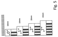
- Figure 5 concerns a ternary coding with the code characters "0", “1” and “2” and a separator character “T".
- the code character “0” is applied here as dhdhh to the piston rod. With a length of 2 mm for a light and a dark stripe, this results in a total physical length of 10 mm on the piston rod.
- the code character “1” is encoded from the code elements dhdhdhh and therefore has a length of 14 mm on the piston rod.
- the code character “2” is composed of the code elements dhdhdhdhh with a physical length of 18 mm.
- the code character “T” contains an additional sequence dh compared to the "2” and thus forms the code character sequence: dhdhdhdhdhh.
- the physical length on the piston rod is therefore 22 mm.
- code words and code word pairs in a ternary i.e. a 3-adic representation
- a particular advantage of coding with code word pairs of equal length is that when manufacturing one or more piston rods, a single continuous marking can be applied to a piston rod that has not yet been split or shortened, and this can then be split and/or shortened without regard to the position of the marking in order to be used in a specific installation environment.
- the continuous marking does not contain any repetitions of the code word pairs and is therefore unambiguous. This advantage is particularly evident in ternary coding.
Landscapes
- Physics & Mathematics (AREA)
- General Physics & Mathematics (AREA)
- Pistons, Piston Rings, And Cylinders (AREA)
Claims (10)
- Cylindre (1) doté d'une tige de piston (3) et d'un dispositif optique de mesure de la position, lequel est orienté vers un marquage (5) disposé sur la tige de piston (3), lequel présente un certain nombre de mots de code, dans lequel chaque mot de code est constitué de deux ou plusieurs signes de code et d'un signe de séparation et chacun des deux ou plusieurs signes de code et de séparation est constitué d'une succession d'éléments de code (h, d), lesquels sont sélectionnés parmi une quantité d'au moins deux éléments de code (h, d) lisibles par le capteur de position et appliqués sur la tige de piston, dans lequel- des signes de code différents de b (0, 1, 2, ..., b-1) sont formés dans une représentation b-adique à partir des éléments de code (h, d),- deux ou plusieurs des signes de code (0, 1, 2, ..., b-1) forment un mot de code dans la représentation b-adique et- chaque mot de code possède n signes de code,caractérisé en ce que le marquage (5) présente une pluralité de paires de mots de code constituées de mots de code adjacents dans la direction de mesure, lesquels présentent une longueur totale physique prédéfinie par paires sur la tige de piston, dans lequel la longueur totale physique est égale pour toutes les paires de mots de code.
- Cylindre selon la revendication 1, caractérisé en ce que b=2 est fixé et les mots de code sont présentés dans un codage binaire.
- Cylindre selon la revendication 2, caractérisé en ce que la somme de deux mots de code d'une paire de mots de code donne un mot de code de somme, lequel ne contient que des uns.
- Cylindre selon la revendication 1, caractérisé en ce que b=3 est fixé et les mots de code sont présentés dans un codage ternaire.
- Cylindre selon la revendication 4, caractérisé en ce que la somme de deux mots de code d'une paire de mots de code donne un mot de code de somme, lequel ne contient que des deux.
- Cylindre (1) selon l'une des revendications 1 à 5, caractérisé en ce que les deux mots de code dans une paire de mots de code présentent conjointement deux signes de séparation.
- Cylindre (1) selon l'une des revendications 1 à 6, caractérisé en ce que deux mots de code séparés l'un de l'autre par un signe de séparation, lesquels présentent respectivement n signes de code, se distinguent l'un de l'autre par une distance maximale.
- Cylindre (1) selon la revendication 7, caractérisé en ce que les mots de code d'une paire de mots de code se distinguent l'un de l'autre dans tous leurs signes de code.
- Cylindre selon l'une des revendications 1 à 8, caractérisé en ce que les éléments de code (h, d) sont formés par des rayures claires et foncées sur la tige de piston.
- Cylindre selon l'une des revendications 1 à 9, caractérisé en ce que les éléments de code (h, d) sont formés par des rayures claires et foncées de même longueur physique sur la tige de piston.
Priority Applications (1)
| Application Number | Priority Date | Filing Date | Title |
|---|---|---|---|
| EP19156224.8A EP3693708B1 (fr) | 2019-02-08 | 2019-02-08 | Cylindre doté d'une tige de piston et d'un dispositif optique de mesure de la position |
Applications Claiming Priority (1)
| Application Number | Priority Date | Filing Date | Title |
|---|---|---|---|
| EP19156224.8A EP3693708B1 (fr) | 2019-02-08 | 2019-02-08 | Cylindre doté d'une tige de piston et d'un dispositif optique de mesure de la position |
Publications (2)
| Publication Number | Publication Date |
|---|---|
| EP3693708A1 EP3693708A1 (fr) | 2020-08-12 |
| EP3693708B1 true EP3693708B1 (fr) | 2024-07-17 |
Family
ID=65365871
Family Applications (1)
| Application Number | Title | Priority Date | Filing Date |
|---|---|---|---|
| EP19156224.8A Active EP3693708B1 (fr) | 2019-02-08 | 2019-02-08 | Cylindre doté d'une tige de piston et d'un dispositif optique de mesure de la position |
Country Status (1)
| Country | Link |
|---|---|
| EP (1) | EP3693708B1 (fr) |
Family Cites Families (7)
| Publication number | Priority date | Publication date | Assignee | Title |
|---|---|---|---|---|
| DE3634730A1 (de) | 1986-10-11 | 1988-04-21 | Klaus Huegler | Arbeitszylinder, insbesondere pneumatikzylinder fuer komponenten von handlingautomaten |
| FI91325C (fi) | 1992-04-07 | 1994-06-10 | Partek Cargotec Oy | Paikka-asteikko ja optinen lukuanturi tämän paikka-asteikon lukemiseksi |
| NL9201059A (nl) | 1992-06-15 | 1994-01-03 | Bootsman Holding Bv | Positiedetectiesysteem. |
| DE4397478T1 (de) * | 1993-07-02 | 1996-06-27 | Partek Cargotec Oy | Hydraulischer, pneumatischer oder ähnlicher Zylinder |
| GB9807020D0 (en) | 1998-04-02 | 1998-06-03 | Bamford Excavators Ltd | A method of marking a mechanical element, an encoding scheme, a reading means for said marking and an apparatus for determining the position of said element |
| GB0419882D0 (en) * | 2004-09-08 | 2004-10-13 | Bamford Excavators Ltd | Calculation module |
| EP3289316B1 (fr) * | 2015-04-30 | 2022-10-12 | PerkinElmer Health Sciences, Inc. | Codeurs, procédés de codage et systèmes et dispositifs dans lesquels ils sont employés |
-
2019
- 2019-02-08 EP EP19156224.8A patent/EP3693708B1/fr active Active
Also Published As
| Publication number | Publication date |
|---|---|
| EP3693708A1 (fr) | 2020-08-12 |
Similar Documents
| Publication | Publication Date | Title |
|---|---|---|
| EP2561319B1 (fr) | Dispositif de détection de position et procédé de fabrication d'un agencement de marquage pour un dispositif de détection de position | |
| DE3688909T2 (de) | Messanordnung mit versetzung. | |
| EP0118673B1 (fr) | Dispositif de mesure | |
| DE69307135T2 (de) | Positionsskala und optischer lesesensor zum lesen derselben | |
| EP0172323B1 (fr) | Appareil de mesure | |
| DE2216013A1 (de) | Verfahren und Gerät zum optischen Lesen eines Binärkodes | |
| DE3013554C2 (de) | Schaltungsanordnung zum Auswerten von unterschiedlichen Synchronisationssignalen | |
| EP4242595B1 (fr) | Dispositif et procédé de détermination de position, de longueur ou d'angle | |
| EP3070342B1 (fr) | Vérin | |
| DE2645460C2 (de) | Verfahren und Vorrichtung zum Auswerten von selbsttaktierend codierten Signalen | |
| DE102017002683A1 (de) | Photoelektrische Codiervorrichtung | |
| DE3490549T1 (de) | Photoelektrisches Verschiebungsermittlungsgerät | |
| DE2549087B2 (de) | Aufzeichnungsträger mit Codemarkierungen von zirkularer Form | |
| DE4309863C1 (de) | Positionsmeßeinrichtung sowie Verfahren zum Ablesen eines binären Codewortes | |
| DE1951713B2 (de) | Anlage zum Ablesen von Markierungen | |
| DE102017118509B4 (de) | Zylinder mit einer Kolbenstange und einem optischen Positionsmesser | |
| DE102013220747A1 (de) | Maßverkörperung für ein absolutes Positionsmesssystem | |
| EP3693708B1 (fr) | Cylindre doté d'une tige de piston et d'un dispositif optique de mesure de la position | |
| DE102017204871A1 (de) | Energiesparendes Positionsbestimmungsverfahren | |
| DE102016103721A1 (de) | Zylinder mit einem optischen Positionssensor | |
| DD159211A1 (de) | Anordnung zur lagebestimmung eines index gegenueber einer teilung | |
| DE3623449C2 (fr) | ||
| DE2502304C2 (de) | Kernreaktor-Brennelement mit einem Identifizierungsteil | |
| DE2301061A1 (de) | Verfahren und vorrichtung zur pruefung der richtigkeit einer information waehrend einer optischen ablesung von datentraegern | |
| EP4375621B1 (fr) | Dispositif et procédé de détermination de position, de longueur ou d'angle |
Legal Events
| Date | Code | Title | Description |
|---|---|---|---|
| PUAI | Public reference made under article 153(3) epc to a published international application that has entered the european phase |
Free format text: ORIGINAL CODE: 0009012 |
|
| STAA | Information on the status of an ep patent application or granted ep patent |
Free format text: STATUS: THE APPLICATION HAS BEEN PUBLISHED |
|
| AK | Designated contracting states |
Kind code of ref document: A1 Designated state(s): AL AT BE BG CH CY CZ DE DK EE ES FI FR GB GR HR HU IE IS IT LI LT LU LV MC MK MT NL NO PL PT RO RS SE SI SK SM TR |
|
| AX | Request for extension of the european patent |
Extension state: BA ME |
|
| STAA | Information on the status of an ep patent application or granted ep patent |
Free format text: STATUS: REQUEST FOR EXAMINATION WAS MADE |
|
| 17P | Request for examination filed |
Effective date: 20210127 |
|
| RBV | Designated contracting states (corrected) |
Designated state(s): AL AT BE BG CH CY CZ DE DK EE ES FI FR GB GR HR HU IE IS IT LI LT LU LV MC MK MT NL NO PL PT RO RS SE SI SK SM TR |
|
| STAA | Information on the status of an ep patent application or granted ep patent |
Free format text: STATUS: EXAMINATION IS IN PROGRESS |
|
| 17Q | First examination report despatched |
Effective date: 20210514 |
|
| P01 | Opt-out of the competence of the unified patent court (upc) registered |
Effective date: 20230628 |
|
| GRAP | Despatch of communication of intention to grant a patent |
Free format text: ORIGINAL CODE: EPIDOSNIGR1 |
|
| STAA | Information on the status of an ep patent application or granted ep patent |
Free format text: STATUS: GRANT OF PATENT IS INTENDED |
|
| INTG | Intention to grant announced |
Effective date: 20240409 |
|
| GRAS | Grant fee paid |
Free format text: ORIGINAL CODE: EPIDOSNIGR3 |
|
| GRAA | (expected) grant |
Free format text: ORIGINAL CODE: 0009210 |
|
| STAA | Information on the status of an ep patent application or granted ep patent |
Free format text: STATUS: THE PATENT HAS BEEN GRANTED |
|
| AK | Designated contracting states |
Kind code of ref document: B1 Designated state(s): AL AT BE BG CH CY CZ DE DK EE ES FI FR GB GR HR HU IE IS IT LI LT LU LV MC MK MT NL NO PL PT RO RS SE SI SK SM TR |
|
| REG | Reference to a national code |
Ref country code: CH Ref legal event code: EP |
|
| REG | Reference to a national code |
Ref country code: DE Ref legal event code: R096 Ref document number: 502019011666 Country of ref document: DE |
|
| REG | Reference to a national code |
Ref country code: IE Ref legal event code: FG4D Free format text: LANGUAGE OF EP DOCUMENT: GERMAN |
|
| REG | Reference to a national code |
Ref country code: LT Ref legal event code: MG9D |
|
| REG | Reference to a national code |
Ref country code: NL Ref legal event code: MP Effective date: 20240717 |
|
| PG25 | Lapsed in a contracting state [announced via postgrant information from national office to epo] |
Ref country code: PT Free format text: LAPSE BECAUSE OF FAILURE TO SUBMIT A TRANSLATION OF THE DESCRIPTION OR TO PAY THE FEE WITHIN THE PRESCRIBED TIME-LIMIT Effective date: 20241118 |
|
| PG25 | Lapsed in a contracting state [announced via postgrant information from national office to epo] |
Ref country code: NL Free format text: LAPSE BECAUSE OF FAILURE TO SUBMIT A TRANSLATION OF THE DESCRIPTION OR TO PAY THE FEE WITHIN THE PRESCRIBED TIME-LIMIT Effective date: 20240717 |
|
| PG25 | Lapsed in a contracting state [announced via postgrant information from national office to epo] |
Ref country code: PT Free format text: LAPSE BECAUSE OF FAILURE TO SUBMIT A TRANSLATION OF THE DESCRIPTION OR TO PAY THE FEE WITHIN THE PRESCRIBED TIME-LIMIT Effective date: 20241118 Ref country code: NL Free format text: LAPSE BECAUSE OF FAILURE TO SUBMIT A TRANSLATION OF THE DESCRIPTION OR TO PAY THE FEE WITHIN THE PRESCRIBED TIME-LIMIT Effective date: 20240717 |
|
| PG25 | Lapsed in a contracting state [announced via postgrant information from national office to epo] |
Ref country code: NO Free format text: LAPSE BECAUSE OF FAILURE TO SUBMIT A TRANSLATION OF THE DESCRIPTION OR TO PAY THE FEE WITHIN THE PRESCRIBED TIME-LIMIT Effective date: 20241017 |
|
| PG25 | Lapsed in a contracting state [announced via postgrant information from national office to epo] |
Ref country code: GR Free format text: LAPSE BECAUSE OF FAILURE TO SUBMIT A TRANSLATION OF THE DESCRIPTION OR TO PAY THE FEE WITHIN THE PRESCRIBED TIME-LIMIT Effective date: 20241018 Ref country code: FI Free format text: LAPSE BECAUSE OF FAILURE TO SUBMIT A TRANSLATION OF THE DESCRIPTION OR TO PAY THE FEE WITHIN THE PRESCRIBED TIME-LIMIT Effective date: 20240717 Ref country code: PL Free format text: LAPSE BECAUSE OF FAILURE TO SUBMIT A TRANSLATION OF THE DESCRIPTION OR TO PAY THE FEE WITHIN THE PRESCRIBED TIME-LIMIT Effective date: 20240717 |
|
| PG25 | Lapsed in a contracting state [announced via postgrant information from national office to epo] |
Ref country code: BG Free format text: LAPSE BECAUSE OF FAILURE TO SUBMIT A TRANSLATION OF THE DESCRIPTION OR TO PAY THE FEE WITHIN THE PRESCRIBED TIME-LIMIT Effective date: 20240717 |
|
| PG25 | Lapsed in a contracting state [announced via postgrant information from national office to epo] |
Ref country code: LV Free format text: LAPSE BECAUSE OF FAILURE TO SUBMIT A TRANSLATION OF THE DESCRIPTION OR TO PAY THE FEE WITHIN THE PRESCRIBED TIME-LIMIT Effective date: 20240717 |
|
| PG25 | Lapsed in a contracting state [announced via postgrant information from national office to epo] |
Ref country code: IS Free format text: LAPSE BECAUSE OF FAILURE TO SUBMIT A TRANSLATION OF THE DESCRIPTION OR TO PAY THE FEE WITHIN THE PRESCRIBED TIME-LIMIT Effective date: 20241117 |
|
| PG25 | Lapsed in a contracting state [announced via postgrant information from national office to epo] |
Ref country code: HR Free format text: LAPSE BECAUSE OF FAILURE TO SUBMIT A TRANSLATION OF THE DESCRIPTION OR TO PAY THE FEE WITHIN THE PRESCRIBED TIME-LIMIT Effective date: 20240717 |
|
| PG25 | Lapsed in a contracting state [announced via postgrant information from national office to epo] |
Ref country code: ES Free format text: LAPSE BECAUSE OF FAILURE TO SUBMIT A TRANSLATION OF THE DESCRIPTION OR TO PAY THE FEE WITHIN THE PRESCRIBED TIME-LIMIT Effective date: 20240717 Ref country code: RS Free format text: LAPSE BECAUSE OF FAILURE TO SUBMIT A TRANSLATION OF THE DESCRIPTION OR TO PAY THE FEE WITHIN THE PRESCRIBED TIME-LIMIT Effective date: 20241017 |
|
| PG25 | Lapsed in a contracting state [announced via postgrant information from national office to epo] |
Ref country code: RS Free format text: LAPSE BECAUSE OF FAILURE TO SUBMIT A TRANSLATION OF THE DESCRIPTION OR TO PAY THE FEE WITHIN THE PRESCRIBED TIME-LIMIT Effective date: 20241017 Ref country code: PL Free format text: LAPSE BECAUSE OF FAILURE TO SUBMIT A TRANSLATION OF THE DESCRIPTION OR TO PAY THE FEE WITHIN THE PRESCRIBED TIME-LIMIT Effective date: 20240717 Ref country code: NO Free format text: LAPSE BECAUSE OF FAILURE TO SUBMIT A TRANSLATION OF THE DESCRIPTION OR TO PAY THE FEE WITHIN THE PRESCRIBED TIME-LIMIT Effective date: 20241017 Ref country code: LV Free format text: LAPSE BECAUSE OF FAILURE TO SUBMIT A TRANSLATION OF THE DESCRIPTION OR TO PAY THE FEE WITHIN THE PRESCRIBED TIME-LIMIT Effective date: 20240717 Ref country code: IS Free format text: LAPSE BECAUSE OF FAILURE TO SUBMIT A TRANSLATION OF THE DESCRIPTION OR TO PAY THE FEE WITHIN THE PRESCRIBED TIME-LIMIT Effective date: 20241117 Ref country code: HR Free format text: LAPSE BECAUSE OF FAILURE TO SUBMIT A TRANSLATION OF THE DESCRIPTION OR TO PAY THE FEE WITHIN THE PRESCRIBED TIME-LIMIT Effective date: 20240717 Ref country code: GR Free format text: LAPSE BECAUSE OF FAILURE TO SUBMIT A TRANSLATION OF THE DESCRIPTION OR TO PAY THE FEE WITHIN THE PRESCRIBED TIME-LIMIT Effective date: 20241018 Ref country code: FI Free format text: LAPSE BECAUSE OF FAILURE TO SUBMIT A TRANSLATION OF THE DESCRIPTION OR TO PAY THE FEE WITHIN THE PRESCRIBED TIME-LIMIT Effective date: 20240717 Ref country code: ES Free format text: LAPSE BECAUSE OF FAILURE TO SUBMIT A TRANSLATION OF THE DESCRIPTION OR TO PAY THE FEE WITHIN THE PRESCRIBED TIME-LIMIT Effective date: 20240717 Ref country code: BG Free format text: LAPSE BECAUSE OF FAILURE TO SUBMIT A TRANSLATION OF THE DESCRIPTION OR TO PAY THE FEE WITHIN THE PRESCRIBED TIME-LIMIT Effective date: 20240717 |
|
| PG25 | Lapsed in a contracting state [announced via postgrant information from national office to epo] |
Ref country code: SM Free format text: LAPSE BECAUSE OF FAILURE TO SUBMIT A TRANSLATION OF THE DESCRIPTION OR TO PAY THE FEE WITHIN THE PRESCRIBED TIME-LIMIT Effective date: 20240717 Ref country code: DK Free format text: LAPSE BECAUSE OF FAILURE TO SUBMIT A TRANSLATION OF THE DESCRIPTION OR TO PAY THE FEE WITHIN THE PRESCRIBED TIME-LIMIT Effective date: 20240717 Ref country code: RO Free format text: LAPSE BECAUSE OF FAILURE TO SUBMIT A TRANSLATION OF THE DESCRIPTION OR TO PAY THE FEE WITHIN THE PRESCRIBED TIME-LIMIT Effective date: 20240717 |
|
| REG | Reference to a national code |
Ref country code: DE Ref legal event code: R097 Ref document number: 502019011666 Country of ref document: DE |
|
| PG25 | Lapsed in a contracting state [announced via postgrant information from national office to epo] |
Ref country code: EE Free format text: LAPSE BECAUSE OF FAILURE TO SUBMIT A TRANSLATION OF THE DESCRIPTION OR TO PAY THE FEE WITHIN THE PRESCRIBED TIME-LIMIT Effective date: 20240717 |
|
| PG25 | Lapsed in a contracting state [announced via postgrant information from national office to epo] |
Ref country code: CZ Free format text: LAPSE BECAUSE OF FAILURE TO SUBMIT A TRANSLATION OF THE DESCRIPTION OR TO PAY THE FEE WITHIN THE PRESCRIBED TIME-LIMIT Effective date: 20240717 |
|
| PG25 | Lapsed in a contracting state [announced via postgrant information from national office to epo] |
Ref country code: SK Free format text: LAPSE BECAUSE OF FAILURE TO SUBMIT A TRANSLATION OF THE DESCRIPTION OR TO PAY THE FEE WITHIN THE PRESCRIBED TIME-LIMIT Effective date: 20240717 |
|
| PLBE | No opposition filed within time limit |
Free format text: ORIGINAL CODE: 0009261 |
|
| STAA | Information on the status of an ep patent application or granted ep patent |
Free format text: STATUS: NO OPPOSITION FILED WITHIN TIME LIMIT |
|
| 26N | No opposition filed |
Effective date: 20250422 |
|
| PG25 | Lapsed in a contracting state [announced via postgrant information from national office to epo] |
Ref country code: SE Free format text: LAPSE BECAUSE OF FAILURE TO SUBMIT A TRANSLATION OF THE DESCRIPTION OR TO PAY THE FEE WITHIN THE PRESCRIBED TIME-LIMIT Effective date: 20240717 |
|
| PG25 | Lapsed in a contracting state [announced via postgrant information from national office to epo] |
Ref country code: MC Free format text: LAPSE BECAUSE OF FAILURE TO SUBMIT A TRANSLATION OF THE DESCRIPTION OR TO PAY THE FEE WITHIN THE PRESCRIBED TIME-LIMIT Effective date: 20240717 |
|
| REG | Reference to a national code |
Ref country code: CH Ref legal event code: PL |
|
| PG25 | Lapsed in a contracting state [announced via postgrant information from national office to epo] |
Ref country code: LU Free format text: LAPSE BECAUSE OF NON-PAYMENT OF DUE FEES Effective date: 20250208 |
|
| PG25 | Lapsed in a contracting state [announced via postgrant information from national office to epo] |
Ref country code: CH Free format text: LAPSE BECAUSE OF NON-PAYMENT OF DUE FEES Effective date: 20250228 |
|
| GBPC | Gb: european patent ceased through non-payment of renewal fee |
Effective date: 20250208 |
|
| REG | Reference to a national code |
Ref country code: BE Ref legal event code: MM Effective date: 20250228 |
|
| PG25 | Lapsed in a contracting state [announced via postgrant information from national office to epo] |
Ref country code: GB Free format text: LAPSE BECAUSE OF NON-PAYMENT OF DUE FEES Effective date: 20250208 |
|
| PG25 | Lapsed in a contracting state [announced via postgrant information from national office to epo] |
Ref country code: BE Free format text: LAPSE BECAUSE OF NON-PAYMENT OF DUE FEES Effective date: 20250228 |
|
| PG25 | Lapsed in a contracting state [announced via postgrant information from national office to epo] |
Ref country code: IE Free format text: LAPSE BECAUSE OF NON-PAYMENT OF DUE FEES Effective date: 20250208 |
|
| PG25 | Lapsed in a contracting state [announced via postgrant information from national office to epo] |
Ref country code: IT Free format text: LAPSE BECAUSE OF FAILURE TO SUBMIT A TRANSLATION OF THE DESCRIPTION OR TO PAY THE FEE WITHIN THE PRESCRIBED TIME-LIMIT Effective date: 20240717 |
|
| PGFP | Annual fee paid to national office [announced via postgrant information from national office to epo] |
Ref country code: DE Payment date: 20260217 Year of fee payment: 8 |
|
| PG25 | Lapsed in a contracting state [announced via postgrant information from national office to epo] |
Ref country code: AT Free format text: LAPSE BECAUSE OF NON-PAYMENT OF DUE FEES Effective date: 20250208 |
|
| REG | Reference to a national code |
Ref country code: AT Ref legal event code: MM01 Ref document number: 1704536 Country of ref document: AT Kind code of ref document: T Effective date: 20250208 |
|
| PGFP | Annual fee paid to national office [announced via postgrant information from national office to epo] |
Ref country code: FR Payment date: 20260219 Year of fee payment: 8 |