EP3693826A1 - Sich bewegendes fahrzeug - Google Patents
Sich bewegendes fahrzeug Download PDFInfo
- Publication number
- EP3693826A1 EP3693826A1 EP18865008.9A EP18865008A EP3693826A1 EP 3693826 A1 EP3693826 A1 EP 3693826A1 EP 18865008 A EP18865008 A EP 18865008A EP 3693826 A1 EP3693826 A1 EP 3693826A1
- Authority
- EP
- European Patent Office
- Prior art keywords
- target
- mobile vehicle
- point
- distance
- axis
- Prior art date
- Legal status (The legal status is an assumption and is not a legal conclusion. Google has not performed a legal analysis and makes no representation as to the accuracy of the status listed.)
- Granted
Links
Images



Classifications
-
- G—PHYSICS
- G05—CONTROLLING; REGULATING
- G05D—SYSTEMS FOR CONTROLLING OR REGULATING NON-ELECTRIC VARIABLES
- G05D1/00—Control of position, course, altitude or attitude of land, water, air or space vehicles, e.g. using automatic pilots
- G05D1/02—Control of position or course in two dimensions
- G05D1/021—Control of position or course in two dimensions specially adapted to land vehicles
- G05D1/0231—Control of position or course in two dimensions specially adapted to land vehicles using optical position detecting means
- G05D1/0238—Control of position or course in two dimensions specially adapted to land vehicles using optical position detecting means using obstacle or wall sensors
- G05D1/024—Control of position or course in two dimensions specially adapted to land vehicles using optical position detecting means using obstacle or wall sensors in combination with a laser
-
- G—PHYSICS
- G05—CONTROLLING; REGULATING
- G05D—SYSTEMS FOR CONTROLLING OR REGULATING NON-ELECTRIC VARIABLES
- G05D1/00—Control of position, course, altitude or attitude of land, water, air or space vehicles, e.g. using automatic pilots
- G05D1/0088—Control of position, course, altitude or attitude of land, water, air or space vehicles, e.g. using automatic pilots characterized by the autonomous decision making process, e.g. artificial intelligence, predefined behaviours
-
- G—PHYSICS
- G05—CONTROLLING; REGULATING
- G05D—SYSTEMS FOR CONTROLLING OR REGULATING NON-ELECTRIC VARIABLES
- G05D1/00—Control of position, course, altitude or attitude of land, water, air or space vehicles, e.g. using automatic pilots
- G05D1/12—Target-seeking control
Definitions
- the present invention relates to a mobile vehicle that follows a follow target detected by a sensor.
- Patent Document 1 discloses a transfer robot that recognizes a transfer worker and follows the transfer worker while keeping a predetermined distance to the transfer worker. When following the transfer worker, the transfer robot detects the transfer worker and obstacles in the surroundings using a detecting section. When stopping being able to recognize the transfer worker, the transfer robot recognizes the existence of a corner in the vicinity of that spot and turns the corner.
- Patent Document 1 Japanese Laid-Open Patent Publication No. 2004-126802
- the solid line indicates the traveling path of a follow target 110 when turning a corner.
- the broken line indicates the traveling path of a machine base 100 that recognizes the follow target 110 with a sensor, for example, a laser sensor, and follows the follow target 110.
- the machine base 100 takes the shortest path toward the follow target 110. Accordingly, the machine base 100 advances along a path different from the path of the follow target 110 by taking a shortcut of the right angle path.
- the follow target 110 travels in a straight line to the corner and changes the traveling direction at the corner as shown in Fig. 16 .
- the machine base 100 gradually changes its traveling direction to move toward points on the traveling path of the follow target 110 respectively shown in Figs. 16B, 16C, and 16D .
- the machine base 100 follows the follow target 110 in the smallest distance without moving along the corner.
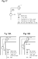
- the machine base 100 may hit an obstacle as shown in Fig. 17 .
- the sensor cannot detect the obstacle.
- the machine base 100 may hit or run onto the obstacle.
- the follow target 110 which is a person, turns a corner of the restricted area
- the machine base 100 may enter the restricted area. Further, at a blind corner as shown in Figs. 18A and 18B , the machine base 100 may lose sight of the follow target 110.
- a mobile vehicle includes one or more wheels, a sensor configured to detect a position of a follow target, and a controlling section configured to control the one or more wheels based on a detection result of the sensor such that the mobile vehicle follows the follow target.
- the controlling section is configured to determine a change point at which a traveling direction of the follow target has changed based on the detection result of the sensor, and set a target point based on the change point.
- the controlling section of the above-described mobile vehicle sets a target point based on the change point. Since there is no obstacle on the path through which the follow target has traveled, the mobile vehicle can follow the follow target while following along the path of the follow target.
- the controlling section may be configured to store in a memory pieces of positional data of the follow target that have been detected by the sensor at predetermined time intervals, and determine the change point based on the pieces of the stored positional data.
- a coordinate system may be defined in which a directional axis from the mobile vehicle toward the follow target is a first axis, and a directional axis orthogonal to the first axis is a second axis, and the controlling section may exclude, from candidates for the change point, a position at which an absolute value of a coordinate on the second axis is smaller than or equal to a threshold on the coordinate system.
- the controlling section may be configured to determine that the change point is a position that corresponds to one of the pieces of the stored positional data and meets one or more conditions.
- a coordinate system may be defined in which a directional axis from the mobile vehicle toward the follow target is a first axis, and a directional axis orthogonal to the first axis is a second axis, and the one or more conditions may include a condition that an absolute value of a coordinate on the second axis is greatest on the coordinate system.
- a coordinate system may be defined in which a directional axis from the mobile vehicle toward the follow target is a first axis, and a directional axis orthogonal to the first axis is a second axis, and the one or more conditions may include a condition that an absolute value of a coordinate on the second axis is greater than a threshold on the coordinate system.
- the one or more conditions may include that a distance from the mobile vehicle is greater than or equal to a predetermined distance.
- the controlling section may be configured to set the target point to a position that is advanced from the change point by a specified distance.
- the controlling section may be configured to stop traveling of the mobile vehicle toward the target point when a distance from the mobile vehicle to the target point is smaller than or equal to the specified distance.
- the controlling section may be configured to cause, when the distance from the mobile vehicle to the target point is greater than the specified distance and smaller than or equal to a speed determination distance, the mobile vehicle to travel toward the target point at a higher speed as the distance to the target point increases.
- the controlling section may be configured to cause, when the distance from the mobile vehicle to the target point is greater than the speed determination distance and smaller than or equal to a stopping determination distance, the mobile vehicle to travel toward the target point at a constant speed equal to that in a case in which the distance to the target point is equal to the speed determination distance.
- the controlling section may be configured to stop traveling of the mobile vehicle toward the target point when the distance from the mobile vehicle to the target point is greater than the stopping determination distance.
- the one or more wheels may include a plurality of omnidirectional wheels, and the controlling section may be configured to control the omnidirectional wheels such that the follow target is located in front of the mobile vehicle.
- the target point may be a target point of traveling and is set at a positon different from a current position of the follow target so as to cause the mobile vehicle to change the traveling direction at the change point.
- the controlling section may be configured to cause the mobile vehicle to travel toward the follow target when the change point is not determined, and cause the mobile vehicle to travel toward the target point that is set based on the change point when the change point is determined.
- a vehicle 10 is an omnidirectional vehicle.
- the vehicle 10 includes a machine base 20 and four wheels 30, 31, 32, 33.
- the four wheels 30, 31, 32, 33 are attached to the machine base 20.
- the wheels 30, 31, 32, 33 are arranged at every 90 degrees about the center of the machine base 20 in a plan view.
- the wheels 30, 31, 32, 33 are omnidirectional wheels, for example, omni wheels.
- the wheels 30, 31, 32, 33 are configured to be driven in all directions. That is, each wheel has multiple rollers (barrel-shaped small wheels), which are arranged along the circumference and freely rotational. This allows the wheel to move freely forward, backward, leftward, and rightward.
- the vehicle 10 is configured to move the machine base 20 in any direction by using the four wheels having the above-described configuration without shifting the axles.
- a sensor 65 is attached to the machine base 20.
- the sensor 65 has a field of view of a predetermined angle in the horizontal direction (detection range).
- the sensor 65 is fixed to the front side of the machine base 20 so that the field of view matches with the front of the machine base 20.
- the sensor 65 is a distance sensor that uses a laser range finder (LRF).
- LRF laser range finder
- the vehicle 10 includes motors 40, 41, 42, 43 and a drive circuit 50.
- the motors 40, 41, 42, 43 and the drive circuit 50 are mounted on the machine base 20.
- the output shafts of the motors 40, 41, 42, 43 are respectively coupled to the corresponding wheels 30, 31, 32, 33 to transmit drive force.
- the motors 40, 41, 42, 43 respectively drive the wheels 30, 31, 32, 33.
- the drive circuit 50 includes a controller 60, which is a controlling section, drive circuits 61, 62, 63, 64, and a memory 66.
- the controller 60 is constituted as a computer including a CPU and memories (a ROM 54 and a RAM) and executes various types of control by executing programs stored in the memories using the CPU.
- the memories, or computer readable media include any type of media that are accessible by general-purpose computers and dedicated computers.
- the controller 60 is not limited to one that performs software processing on all processes executed by itself.
- the controller 60 may include dedicated hardware circuit (for example, an application specific integrated circuit: ASIC) that executes at least part of the processes executed by itself. That is, the controller 60 may be circuitry including 1) one or more processors that operate according to a computer program (software), 2) one or more dedicated hardware circuits that execute at least part of various types of processes, or 3) a combination thereof.
- ASIC application specific integrated circuit
- the controller 60 receives detection signals from the sensor 65.
- the detection signal of the sensor 65 contains information of detected objects around the vehicle 10 including a follow target.
- the drive circuit 61 activates the motor 40, which in turn rotates the wheel 30.
- the drive circuit 62 activates the motor 41, which in turn rotates the wheel 31.
- the drive circuit 63 activates the motor 42, which in turn rotates the wheel 32.
- the drive circuit 64 activates the motor 43, which in turn rotates the wheel 33.
- the controller 60 controls the respective motors 40, 41, 42, 43 via the corresponding drive circuits 61, 62, 63, 64. Accordingly, the corresponding wheels 30, 31, 32, 33 rotate to cause the machine base 20 to move forward, rearward, leftward, or rightward, or revolve.
- the follow target may be a person (follow-target person) or an object such as a vehicle (follow-target object).
- the sensor 65 detects the position of the follow target and obstacles in the detection range.
- the four-omni wheel vehicle 10 which is an omnidirectional vehicle, is capable of performing free motions including translation, revolution, and diagonal motion.
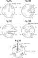
- the vehicle 10 is capable of moving as shown in Figs. 3A, 3B, 3C, 3D, and 3E .
- the machine base 20 advances forward when the wheels 30, 33 rotate in the forward direction and the wheels 31, 32 rotate in the reverse direction as shown in Fig. 3A .
- the machine base 20 moves diagonally when the wheel 31 rotates in the reverse direction and the wheel 33 rotates in the forward direction with the wheels 30, 32 in a stopped state as shown in Fig. 3B .
- the machine base 20 moves sideways when the wheels 30, 31 rotate in the reverse direction and the wheels 32, 33 rotate in the forward direction as shown in Fig. 3C .
- the machine base 20 revolves when the wheels 30, 31, 32, 33 rotate in the forward direction as shown in Fig. 3D .
- the machine base 20 revolves while advancing forward when the wheels 30, 33 rotate in the forward direction and the wheels 31, 32 rotate at predetermined speeds as shown in Fig. 3E .
- the vehicle 10 is capable of performing combination of translation and revolution, that is, moving while causing the machine base 20 to revolve.
- the vehicle 10 when following the follow target 70 that is advancing along a path including a corner as shown in Fig. 5 , the vehicle 10 is capable of moving while causing the machine base 20 to revolve so as to constantly capture the follow target 70 in front, which is the detection direction.
- the controller 60 controls the omnidirectional wheels 30, 31, 32, 33 such that the sensor 65 maintains the position (orientation) to be within the field of view of the follow target 70 as shown in Fig. 5 .
- the controller 60 controls the wheels 30, 31, 32, 33 such that the follow target 70 is located in front of the machine base 20, thereby changing the orientation (position) of the machine base 20 such that the follow target 70 is located in front of the machine base 20.
- the controller 60 is configured to determine a change point Pc, at which the traveling direction of the follow target 70 has changed, based on the detection result of the sensor 65.
- the controller 60 is configured to set a target point Pt (refer to Fig. 6 ) based on the change point Pc (refer to Fig. 9A ).
- the target point Pt is a target point of traveling and is set at a positon different from the current position of the follow target 70 so as to cause the vehicle 10 to change the traveling direction at the change point Pc.
- Figs. 7A, 7B, 7C show the traveling paths of the follow target 70 and the mobile vehicle 10.
- Fig. 7A shows a stage at which the follow target 70 has reached a corner.
- the target point Pt is set on the follow target Pt.
- Fig. 7B shows a stage at which the follow target 70 has changed the traveling direction at the corner.
- the vehicle 10 is moving toward the target point Pt, which has been set based on the change point Pc.
- Fig. 7C shows a stage at which the vehicle 10 has reached the change point Pc.
- the controller 60 puts the target point Pt back onto the follow target 70 and restarts following the follow target 70.
- Position 1 indicates the current position of the follow target 70.
- Positions 2 to 14 are past positions of the follow target 70 that go back in order from Position 1. Positions 2 to 14 were recorded every 50 msec.
- the controller 60 is configured to store positional data of the follow target 70 that is detected at predetermined time intervals (every 50 msec) in the memory 66 and to determine the change point Pc based on the pieces of the stored positional data.
- the pieces of past positional data (coordinates) of the follow target 70 are retained on a relative coordinate system that is defined with the machine base 20 being the center.
- the relative coordinate system is an XY-coordinate system in which, at the current position (present time), the directional axis from the vehicle 10 toward the follow target 70 is the X-axis, or a first axis, and a directional axis orthogonal to the X-axis is a Y-axis, or a second axis.
- the X-axis and the Y-axis intersect with each other at a right angle at the center of the machine base 20, and the intersection is the origin of the XY-coordinate system.
- the X-coordinates from the origin toward the follow target 70 have positive values.
- the memory 66 stores, for example, the immediately preceding 100 positional coordinates on the XY-coordinate system of the follow target 70.
- the controller 60 discards the oldest one of the 100 data pieces and converts the 100 pieces of positional data containing the newly added piece of positional data into the relative coordinate system at the present time. Such conversion of the relative coordinate system is performed each time the machine base 20 revolves. Accordingly, when the control cycle is 50 ms, the controller 60 is capable of reading out the positional data of a period up to 5000 ms (5.0 s) ago (50 ms x 100 times).
- the controller 60 sets the change point Pc to a position that corresponds to one of the pieces of the stored positional data and meets one or more conditions.
- Condition 1 for setting a change point is that the position to be the change point Pc is in front of the machine base 20.
- the X-coordinate of the position to be the change point Pc is greater than zero. This applies not only to a case in which the traveling path of the follow target 70 forms a right angle as shown in Fig. 9A , but also to a case in which the traveling path of the follow target 70 forms a curve.
- Condition 2 for setting a change point is that the absolute value of the coordinate on the second axis (Y-coordinate) is greater than a threshold D.
- the threshold D can be set to 0.6 m, for example.
- > 0.6 that is, the absolute value of the Y-coordinate is greater than the threshold Dm is detected, that position is a candidate for the change point Pc. That is, positions at which the absolute value of the Y-coordinate is greater than the threshold Dm are validated as candidates for the change point Pc, and positions at which the absolute value of the Y-coordinate is smaller than or equal to the threshold Dm are excluded from candidates for the change point Pc.
- the change in the traveling direction of a follow target is recognized, the change is invalidated if its value is smaller than or equal to the threshold Dm.
- the threshold is set to 0.6 m for the following reason. There may be a case in which the sensor 65 successively detects the leg on the rear side of the follow-target person who is walking. In this case, even if the follow target 70 advances in a straight line as shown in Fig. 10 , the Y-coordinate varies by 0.3 to 0.4 m depending on whether the right leg or the left leg is detected. Thus, the follow target 70 appears to be moving in a zig-zag manner from the machine base 20. Without a threshold, the machine base 20 would move in a zig-zag manner even if the follow target 70 moves in a straight line.
- Condition 3 for setting a change point is that the absolute value of the coordinate on the second axis (Y-coordinate) of the position is the greatest. For example, on the XY-coordinate system shown in Fig. 11 , the absolute value of the Y-coordinate of Position 7 (Y7) is the greatest. Position 7 is thus a candidate for the change point Pc.
- Condition 4 for setting a change point may be used.
- Condition 4 is that, when setting a change point Pc, the distance between the vehicle 10 and the change point Pc to be set is greater than or equal to a predetermined distance Dn.
- the predetermined distance Dn may be, for example, 1 m.
- the distances between Positions 7 to 17 and the vehicle 10 are smaller than Dn. These positions are thus excluded from candidates for the change point Pc.
- Position 18 and the positions before position 18 do not meet Condition 1 (X > 0).
- the absolute value of the Y-coordinate of Position 6 (Y6) is the greatest. Position 6 thus meets Condition 3.
- Position 6 Since the X-coordinate of Position 6 (X6) is greater than 0, Position 6 meets Condition 1. Since the Y-coordinate of position 6 (Y6) is greater than the threshold Dm, Position 6 meets Condition 2. In the example shown in Fig. 11 , Position 6, which meets all Conditions 1 to 4, is determined to be the change point Pc.
- the controller 60 sets the target point Pt based on the change point Pc. Specifically, the controller 60 sets the target point Pt to a position that is advanced from the change point Pc by a specified distance Ds.
- the specified distance Ds may be, for example, 0.7 m.
- the target point Pt is set to a point that is advanced from the change point Pc by the specified distance Ds for the following reason.
- the machine base 20 follows the follow target 70 with at least a 0.7 m clearance from the follow target 70 as shown in Fig. 12 .
- the target point Pt is set to the change point Pc
- the machine base 20 will change the traveling direction at a position 0.7 m short of the target.
- the target point Pt is set to a position that is advanced from the change point Pc by another 0.7 m as shown in Fig. 13
- the machine base 20 can change the traveling direction at the change point Pc.
- the target point Pt is set on an extension of the straight line connecting the current positon of the machine base 20 and the change point Pc.
- the controller 60 may change the traveling speed of the vehicle 10 when the vehicle 10 moves toward the target point Pt, which has been set based on the change point Pc.
- the vehicle 10 may travel toward the target point Pt at a higher speed v as the distance Dt to the target point Pt increases.
- the speed determination distance Da may be, for example, 1.8 m.
- the vehicle 10 may travel toward the target point Pt at a constant speed Vf equal to that in a case in which the distance Dt to the target point Pt is equal to the speed determination distance Da.
- the stopping determination distance Db may be, for example, 3 to 10 m.
- the maximum speed of the speed Vf may be, for example, 2.2 m/sec.
- the specified distance Ds ⁇ the speed determination distance Da ⁇ the stopping determination distance Db.
- the vehicle 10 may stop traveling toward the target point Pt when the distance Dt from the vehicle 10 to the target point Pt is smaller than or equal to the specified distance Ds (Dt ⁇ specified distance Ds).
- the vehicle 10 may stop traveling toward the target point Pt when the distance Dt from the vehicle 10 to the target point Pt is greater than the stopping determination distance Db (stopping determination distance Db ⁇ Dt).
- the controller 60 executes the process shown in Fig. 4 at predetermined time intervals, for example, 50 msec.
- a change point reaching flag is set to ON when the vehicle is activated.
- step S101 the sensor 65 detects the positon of the follow target 70.
- step S102 the controller 60 shifts the coordinate arrangement of the follow target 70 backward by one. Specifically, the controller 60 stores the latest positional data, or the positional coordinates, of the follow target 70, which has been detected in step S101 in the memory 66, and discards the oldest positional data.
- step S103 the controller 60 determines whether the change point reaching flag is ON. If the change point reaching flag is ON, the controller 60 proceeds to step S104. If the change point reaching flag is OFF, the controller 60 proceeds to step S108.
- step S104 the controller 60 determines whether there is a change point Pc based on multiple pieces of positional data of the follow target 70 stored in the memory 66.
- the controller 60 searches the past positional coordinates of the follow target 70 (for example, 100 times of detection) and determines that there is a change point Pc if there is a position that meets the above-described Conditions 1 to 4.
- step S104 When there is no change point Pc in step S104, the controller 60 proceeds to step S106 and sets the target point Pt to the follow target 70.
- step S105 When there is a change point Pc in step S104, the controller 60 proceeds to step S105 and sets the target point Pt to a point that is ahead of the change point Pc by 0.7 m. Thereafter, the controller 60 sets the change point reaching flag to OFF in step S107 and ends the process.
- the specified distance Ds is not limited to 0.7 m, but may be adjusted.
- the minimum distance from the machine base 20 to the follow target 70 may be changed from 0.7 m to 0 m, so that the vehicle 10 reaches the target point Pt.
- step S108 the controller 60 determines whether the change point Pc has been reached. When determining that the change point Pc has not been reached, the controller 60 ends the process. In contrast, when determining that the change point Pc has been reached in step S108, the controller 60 proceeds to step S109 and sets the change point reaching flag to ON. Thereafter, the controller 60 ends the process. In step S108, considering errors, the change point Pc may be determined to be reached if the distance from the machine base 20 to the change point Pc is smaller than or equal to 0.1 m.
- step S101, step S102, step S103, step S104, step S106, and End is repeatedly executed.
- step S101, step S102, step S103, step S104, step S105, step S107, and End is executed.
- step S101, step S102, step S103, step S108, and End is repeatedly executed.
- step S101, step S102, step S103, step S108, step S109, and End is executed.
- Fig. 7A since the traveling direction of the follow target 70 does not change, the target point Pt is set on the follow target 70 (step S106).
- Fig. 7B the traveling direction of the follow target 70 changes, and the target point Pt is set based on the change point Pc (step S105).
- the vehicle 10 travels along the substantially the same path along which the follow target 70 has traveled or along a path close to the path along which the follow target 70 has traveled. That is, when turning a corner, the vehicle 10 follows along the traveling path of the follow target 70, but does not directly follow the follow target 70. Since the vehicle 10 follows along the traveling path of the follow target 70, the vehicle 10 does not take a shortcut of the traveling path shown in Figs. 15 , 16A, 16B, 16C, and 16D .
- the vehicle 10 is prevented from taking a shortcut and hitting an obstacle as shown in Fig. 17 . Also, if the follow target 70 avoids a restricted area in a factory while traveling, the vehicle 10 is prevented from accidentally entering the restricted area. Further, the vehicle 10 does not lose sight of the follow target 110 at a blind corner as shown in Figs. 18A and 18B .
- the sensor 65 does not need to be a laser type, but may be, for example, an ultrasonic sensor.
- the omnidirectional vehicle does not need to be an omni wheel type, but may be, for example, a Mecanum wheel type or an omni ball type.
- the vehicle does not need to be an omnidirectional vehicle.
Landscapes
- Engineering & Computer Science (AREA)
- Physics & Mathematics (AREA)
- Automation & Control Theory (AREA)
- Remote Sensing (AREA)
- General Physics & Mathematics (AREA)
- Aviation & Aerospace Engineering (AREA)
- Radar, Positioning & Navigation (AREA)
- Electromagnetism (AREA)
- Optics & Photonics (AREA)
- Medical Informatics (AREA)
- Health & Medical Sciences (AREA)
- Artificial Intelligence (AREA)
- Business, Economics & Management (AREA)
- Game Theory and Decision Science (AREA)
- Evolutionary Computation (AREA)
- Control Of Position, Course, Altitude, Or Attitude Of Moving Bodies (AREA)
Applications Claiming Priority (2)
| Application Number | Priority Date | Filing Date | Title |
|---|---|---|---|
| JP2017196216 | 2017-10-06 | ||
| PCT/JP2018/033354 WO2019069626A1 (ja) | 2017-10-06 | 2018-09-10 | 移動車両 |
Publications (3)
| Publication Number | Publication Date |
|---|---|
| EP3693826A1 true EP3693826A1 (de) | 2020-08-12 |
| EP3693826A4 EP3693826A4 (de) | 2020-09-16 |
| EP3693826B1 EP3693826B1 (de) | 2022-02-23 |
Family
ID=65995390
Family Applications (1)
| Application Number | Title | Priority Date | Filing Date |
|---|---|---|---|
| EP18865008.9A Not-in-force EP3693826B1 (de) | 2017-10-06 | 2018-09-10 | Sich bewegendes fahrzeug |
Country Status (4)
| Country | Link |
|---|---|
| US (1) | US11442461B2 (de) |
| EP (1) | EP3693826B1 (de) |
| JP (1) | JP6825715B2 (de) |
| WO (1) | WO2019069626A1 (de) |
Families Citing this family (4)
| Publication number | Priority date | Publication date | Assignee | Title |
|---|---|---|---|---|
| US12393200B2 (en) | 2020-06-01 | 2025-08-19 | Sony Group Corporation | Information processing device, information processing system, method, and program |
| JP7643457B2 (ja) * | 2020-06-03 | 2025-03-11 | ソニーグループ株式会社 | 情報処理装置、情報処理システム、および方法、並びにプログラム |
| JP7400700B2 (ja) * | 2020-11-19 | 2023-12-19 | 株式会社豊田自動織機 | 全方向移動車の走行制御装置 |
| CN118525258A (zh) * | 2022-02-08 | 2024-08-20 | 索尼集团公司 | 信息处理装置、信息处理方法、信息处理程序和移动装置 |
Family Cites Families (16)
| Publication number | Priority date | Publication date | Assignee | Title |
|---|---|---|---|---|
| JP3875988B2 (ja) * | 2002-05-10 | 2007-01-31 | 本田技研工業株式会社 | 未知の障害物の中の予測不可能な目標物の実時間追跡 |
| JP4245887B2 (ja) * | 2002-09-30 | 2009-04-02 | セコム株式会社 | 搬送ロボット |
| JP4316477B2 (ja) * | 2004-11-18 | 2009-08-19 | パナソニック株式会社 | 移動ロボットの追従方法 |
| JP2006155349A (ja) * | 2004-11-30 | 2006-06-15 | Sony Corp | 追尾方法、追尾装置、追尾システム及び追尾プログラム |
| JP2008084135A (ja) * | 2006-09-28 | 2008-04-10 | Toshiba Corp | 移動制御方法、移動ロボットおよび移動制御プログラム |
| JP5071817B2 (ja) * | 2009-03-31 | 2012-11-14 | 株式会社エクォス・リサーチ | 車両制御装置、車両、及び車両制御プログラム |
| CN102183960B (zh) * | 2011-05-06 | 2013-07-03 | 北京航空航天大学 | 一种适用于独立式自动跟踪的局部可柔度虚杆转弯控制系统 |
| US8510029B2 (en) * | 2011-10-07 | 2013-08-13 | Southwest Research Institute | Waypoint splining for autonomous vehicle following |
| CN105705095B (zh) | 2013-09-06 | 2019-10-08 | 株式会社岛津制作所 | 移动式x射线摄影装置 |
| US9798324B2 (en) * | 2014-07-18 | 2017-10-24 | Helico Aerospace Industries Sia | Autonomous vehicle operation |
| WO2016126297A2 (en) * | 2014-12-24 | 2016-08-11 | Irobot Corporation | Mobile security robot |
| WO2016172002A1 (en) * | 2015-04-22 | 2016-10-27 | Massachusetts Institute Of Technology | Foot touch position following apparatus, method of controlling movement thereof, computer-executable program, and non-transitory computer-readable information recording medium storing the same |
| CN119645078A (zh) * | 2015-09-15 | 2025-03-18 | 深圳市大疆创新科技有限公司 | 控制可移动物体跟踪目标的系统和方法 |
| US20170368690A1 (en) * | 2016-06-27 | 2017-12-28 | Dilili Labs, Inc. | Mobile Robot Navigation |
| TW201805598A (zh) * | 2016-08-04 | 2018-02-16 | 鴻海精密工業股份有限公司 | 自主移動設備及建立導航路徑的方法 |
| US11160340B2 (en) * | 2017-07-10 | 2021-11-02 | Travelmate Robotics, Inc. | Autonomous robot system |
-
2018
- 2018-09-10 EP EP18865008.9A patent/EP3693826B1/de not_active Not-in-force
- 2018-09-10 WO PCT/JP2018/033354 patent/WO2019069626A1/ja not_active Ceased
- 2018-09-10 US US16/652,828 patent/US11442461B2/en active Active
- 2018-09-10 JP JP2019546591A patent/JP6825715B2/ja active Active
Also Published As
| Publication number | Publication date |
|---|---|
| EP3693826A4 (de) | 2020-09-16 |
| JP6825715B2 (ja) | 2021-02-03 |
| US11442461B2 (en) | 2022-09-13 |
| US20200319645A1 (en) | 2020-10-08 |
| EP3693826B1 (de) | 2022-02-23 |
| WO2019069626A1 (ja) | 2019-04-11 |
| JPWO2019069626A1 (ja) | 2020-10-15 |
Similar Documents
| Publication | Publication Date | Title |
|---|---|---|
| EP3693826B1 (de) | Sich bewegendes fahrzeug | |
| CN106022274B (zh) | 一种避障方法、避障装置及无人驾驶机器 | |
| CN113267199B (zh) | 行驶轨迹规划方法及装置 | |
| CN101666649B (zh) | 一种非360°探测机器人的定目标导航方法 | |
| WO2018097026A1 (ja) | 車両制御装置 | |
| CN106843239B (zh) | 基于地图预测的机器人运动控制方法 | |
| US11347227B2 (en) | Autonomous mobile apparatus | |
| JP2007310866A (ja) | 絶対方位角を利用したロボット及びこれを利用したマップ作成方法 | |
| CN112068570B (zh) | 机器人的移动控制方法、装置及机器人 | |
| CN113320526A (zh) | 自主泊车的方法、装置和设备、计算机可读存储介质 | |
| CN114489076A (zh) | 矩形扫地机器人控制方法、装置和矩形扫地机器人 | |
| CN112519782A (zh) | 车辆自动变道方法、装置、车辆以及计算机可读存储介质 | |
| JP2019152575A (ja) | 物体追跡装置、物体追跡方法及び物体追跡用コンピュータプログラム | |
| CN110865640A (zh) | 一种智能机器人的避障结构 | |
| CN115248587A (zh) | 自移动机器人的行进控制方法、装置、设备及存储介质 | |
| JP6962027B2 (ja) | 移動車両 | |
| CN111856443A (zh) | 用于物体跟踪的航向角估算 | |
| JP2020187707A (ja) | 自律移動体 | |
| CN114756014B (zh) | 回归控制方法、自动行走设备以及自动行走系统 | |
| JP7618378B2 (ja) | 自律移動体 | |
| JP2020140477A (ja) | 自律走行体 | |
| JP6642026B2 (ja) | 自律移動体制御装置 | |
| JP2019202642A (ja) | 車両用走行制御装置 | |
| US20230174054A1 (en) | Object recognition device, path planning device, parking support device, object recognition system, path planning system and parking support system | |
| JP6866781B2 (ja) | 移動車両 |
Legal Events
| Date | Code | Title | Description |
|---|---|---|---|
| STAA | Information on the status of an ep patent application or granted ep patent |
Free format text: STATUS: THE INTERNATIONAL PUBLICATION HAS BEEN MADE |
|
| PUAI | Public reference made under article 153(3) epc to a published international application that has entered the european phase |
Free format text: ORIGINAL CODE: 0009012 |
|
| STAA | Information on the status of an ep patent application or granted ep patent |
Free format text: STATUS: REQUEST FOR EXAMINATION WAS MADE |
|
| 17P | Request for examination filed |
Effective date: 20200331 |
|
| AK | Designated contracting states |
Kind code of ref document: A1 Designated state(s): AL AT BE BG CH CY CZ DE DK EE ES FI FR GB GR HR HU IE IS IT LI LT LU LV MC MK MT NL NO PL PT RO RS SE SI SK SM TR |
|
| AX | Request for extension of the european patent |
Extension state: BA ME |
|
| A4 | Supplementary search report drawn up and despatched |
Effective date: 20200819 |
|
| RIC1 | Information provided on ipc code assigned before grant |
Ipc: G05D 1/12 20060101ALI20200813BHEP Ipc: G05D 1/02 20200101AFI20200813BHEP |
|
| DAV | Request for validation of the european patent (deleted) | ||
| DAX | Request for extension of the european patent (deleted) | ||
| GRAP | Despatch of communication of intention to grant a patent |
Free format text: ORIGINAL CODE: EPIDOSNIGR1 |
|
| STAA | Information on the status of an ep patent application or granted ep patent |
Free format text: STATUS: GRANT OF PATENT IS INTENDED |
|
| INTG | Intention to grant announced |
Effective date: 20210917 |
|
| GRAS | Grant fee paid |
Free format text: ORIGINAL CODE: EPIDOSNIGR3 |
|
| GRAA | (expected) grant |
Free format text: ORIGINAL CODE: 0009210 |
|
| STAA | Information on the status of an ep patent application or granted ep patent |
Free format text: STATUS: THE PATENT HAS BEEN GRANTED |
|
| AK | Designated contracting states |
Kind code of ref document: B1 Designated state(s): AL AT BE BG CH CY CZ DE DK EE ES FI FR GB GR HR HU IE IS IT LI LT LU LV MC MK MT NL NO PL PT RO RS SE SI SK SM TR |
|
| REG | Reference to a national code |
Ref country code: GB Ref legal event code: FG4D |
|
| REG | Reference to a national code |
Ref country code: CH Ref legal event code: EP |
|
| REG | Reference to a national code |
Ref country code: AT Ref legal event code: REF Ref document number: 1470940 Country of ref document: AT Kind code of ref document: T Effective date: 20220315 |
|
| REG | Reference to a national code |
Ref country code: IE Ref legal event code: FG4D |
|
| REG | Reference to a national code |
Ref country code: DE Ref legal event code: R096 Ref document number: 602018031410 Country of ref document: DE |
|
| REG | Reference to a national code |
Ref country code: SE Ref legal event code: TRGR |
|
| REG | Reference to a national code |
Ref country code: LT Ref legal event code: MG9D |
|
| REG | Reference to a national code |
Ref country code: NL Ref legal event code: MP Effective date: 20220223 |
|
| REG | Reference to a national code |
Ref country code: AT Ref legal event code: MK05 Ref document number: 1470940 Country of ref document: AT Kind code of ref document: T Effective date: 20220223 |
|
| PG25 | Lapsed in a contracting state [announced via postgrant information from national office to epo] |
Ref country code: RS Free format text: LAPSE BECAUSE OF FAILURE TO SUBMIT A TRANSLATION OF THE DESCRIPTION OR TO PAY THE FEE WITHIN THE PRESCRIBED TIME-LIMIT Effective date: 20220223 Ref country code: PT Free format text: LAPSE BECAUSE OF FAILURE TO SUBMIT A TRANSLATION OF THE DESCRIPTION OR TO PAY THE FEE WITHIN THE PRESCRIBED TIME-LIMIT Effective date: 20220623 Ref country code: NO Free format text: LAPSE BECAUSE OF FAILURE TO SUBMIT A TRANSLATION OF THE DESCRIPTION OR TO PAY THE FEE WITHIN THE PRESCRIBED TIME-LIMIT Effective date: 20220523 Ref country code: NL Free format text: LAPSE BECAUSE OF FAILURE TO SUBMIT A TRANSLATION OF THE DESCRIPTION OR TO PAY THE FEE WITHIN THE PRESCRIBED TIME-LIMIT Effective date: 20220223 Ref country code: LT Free format text: LAPSE BECAUSE OF FAILURE TO SUBMIT A TRANSLATION OF THE DESCRIPTION OR TO PAY THE FEE WITHIN THE PRESCRIBED TIME-LIMIT Effective date: 20220223 Ref country code: HR Free format text: LAPSE BECAUSE OF FAILURE TO SUBMIT A TRANSLATION OF THE DESCRIPTION OR TO PAY THE FEE WITHIN THE PRESCRIBED TIME-LIMIT Effective date: 20220223 Ref country code: ES Free format text: LAPSE BECAUSE OF FAILURE TO SUBMIT A TRANSLATION OF THE DESCRIPTION OR TO PAY THE FEE WITHIN THE PRESCRIBED TIME-LIMIT Effective date: 20220223 Ref country code: BG Free format text: LAPSE BECAUSE OF FAILURE TO SUBMIT A TRANSLATION OF THE DESCRIPTION OR TO PAY THE FEE WITHIN THE PRESCRIBED TIME-LIMIT Effective date: 20220523 |
|
| PG25 | Lapsed in a contracting state [announced via postgrant information from national office to epo] |
Ref country code: PL Free format text: LAPSE BECAUSE OF FAILURE TO SUBMIT A TRANSLATION OF THE DESCRIPTION OR TO PAY THE FEE WITHIN THE PRESCRIBED TIME-LIMIT Effective date: 20220223 Ref country code: LV Free format text: LAPSE BECAUSE OF FAILURE TO SUBMIT A TRANSLATION OF THE DESCRIPTION OR TO PAY THE FEE WITHIN THE PRESCRIBED TIME-LIMIT Effective date: 20220223 Ref country code: GR Free format text: LAPSE BECAUSE OF FAILURE TO SUBMIT A TRANSLATION OF THE DESCRIPTION OR TO PAY THE FEE WITHIN THE PRESCRIBED TIME-LIMIT Effective date: 20220524 Ref country code: FI Free format text: LAPSE BECAUSE OF FAILURE TO SUBMIT A TRANSLATION OF THE DESCRIPTION OR TO PAY THE FEE WITHIN THE PRESCRIBED TIME-LIMIT Effective date: 20220223 Ref country code: AT Free format text: LAPSE BECAUSE OF FAILURE TO SUBMIT A TRANSLATION OF THE DESCRIPTION OR TO PAY THE FEE WITHIN THE PRESCRIBED TIME-LIMIT Effective date: 20220223 |
|
| PG25 | Lapsed in a contracting state [announced via postgrant information from national office to epo] |
Ref country code: IS Free format text: LAPSE BECAUSE OF FAILURE TO SUBMIT A TRANSLATION OF THE DESCRIPTION OR TO PAY THE FEE WITHIN THE PRESCRIBED TIME-LIMIT Effective date: 20220623 |
|
| PG25 | Lapsed in a contracting state [announced via postgrant information from national office to epo] |
Ref country code: SM Free format text: LAPSE BECAUSE OF FAILURE TO SUBMIT A TRANSLATION OF THE DESCRIPTION OR TO PAY THE FEE WITHIN THE PRESCRIBED TIME-LIMIT Effective date: 20220223 Ref country code: SK Free format text: LAPSE BECAUSE OF FAILURE TO SUBMIT A TRANSLATION OF THE DESCRIPTION OR TO PAY THE FEE WITHIN THE PRESCRIBED TIME-LIMIT Effective date: 20220223 Ref country code: RO Free format text: LAPSE BECAUSE OF FAILURE TO SUBMIT A TRANSLATION OF THE DESCRIPTION OR TO PAY THE FEE WITHIN THE PRESCRIBED TIME-LIMIT Effective date: 20220223 Ref country code: EE Free format text: LAPSE BECAUSE OF FAILURE TO SUBMIT A TRANSLATION OF THE DESCRIPTION OR TO PAY THE FEE WITHIN THE PRESCRIBED TIME-LIMIT Effective date: 20220223 Ref country code: DK Free format text: LAPSE BECAUSE OF FAILURE TO SUBMIT A TRANSLATION OF THE DESCRIPTION OR TO PAY THE FEE WITHIN THE PRESCRIBED TIME-LIMIT Effective date: 20220223 Ref country code: CZ Free format text: LAPSE BECAUSE OF FAILURE TO SUBMIT A TRANSLATION OF THE DESCRIPTION OR TO PAY THE FEE WITHIN THE PRESCRIBED TIME-LIMIT Effective date: 20220223 |
|
| PGFP | Annual fee paid to national office [announced via postgrant information from national office to epo] |
Ref country code: SE Payment date: 20220811 Year of fee payment: 5 Ref country code: IT Payment date: 20220811 Year of fee payment: 5 Ref country code: DE Payment date: 20220803 Year of fee payment: 5 |
|
| REG | Reference to a national code |
Ref country code: DE Ref legal event code: R097 Ref document number: 602018031410 Country of ref document: DE |
|
| PG25 | Lapsed in a contracting state [announced via postgrant information from national office to epo] |
Ref country code: AL Free format text: LAPSE BECAUSE OF FAILURE TO SUBMIT A TRANSLATION OF THE DESCRIPTION OR TO PAY THE FEE WITHIN THE PRESCRIBED TIME-LIMIT Effective date: 20220223 |
|
| PLBE | No opposition filed within time limit |
Free format text: ORIGINAL CODE: 0009261 |
|
| STAA | Information on the status of an ep patent application or granted ep patent |
Free format text: STATUS: NO OPPOSITION FILED WITHIN TIME LIMIT |
|
| 26N | No opposition filed |
Effective date: 20221124 |
|
| PG25 | Lapsed in a contracting state [announced via postgrant information from national office to epo] |
Ref country code: SI Free format text: LAPSE BECAUSE OF FAILURE TO SUBMIT A TRANSLATION OF THE DESCRIPTION OR TO PAY THE FEE WITHIN THE PRESCRIBED TIME-LIMIT Effective date: 20220223 |
|
| PG25 | Lapsed in a contracting state [announced via postgrant information from national office to epo] |
Ref country code: MC Free format text: LAPSE BECAUSE OF FAILURE TO SUBMIT A TRANSLATION OF THE DESCRIPTION OR TO PAY THE FEE WITHIN THE PRESCRIBED TIME-LIMIT Effective date: 20220223 |
|
| REG | Reference to a national code |
Ref country code: CH Ref legal event code: PL |
|
| GBPC | Gb: european patent ceased through non-payment of renewal fee |
Effective date: 20220910 |
|
| REG | Reference to a national code |
Ref country code: BE Ref legal event code: MM Effective date: 20220930 |
|
| PG25 | Lapsed in a contracting state [announced via postgrant information from national office to epo] |
Ref country code: LU Free format text: LAPSE BECAUSE OF NON-PAYMENT OF DUE FEES Effective date: 20220910 |
|
| PG25 | Lapsed in a contracting state [announced via postgrant information from national office to epo] |
Ref country code: LI Free format text: LAPSE BECAUSE OF NON-PAYMENT OF DUE FEES Effective date: 20220930 Ref country code: IE Free format text: LAPSE BECAUSE OF NON-PAYMENT OF DUE FEES Effective date: 20220910 Ref country code: FR Free format text: LAPSE BECAUSE OF NON-PAYMENT OF DUE FEES Effective date: 20220930 Ref country code: CH Free format text: LAPSE BECAUSE OF NON-PAYMENT OF DUE FEES Effective date: 20220930 |
|
| PG25 | Lapsed in a contracting state [announced via postgrant information from national office to epo] |
Ref country code: BE Free format text: LAPSE BECAUSE OF NON-PAYMENT OF DUE FEES Effective date: 20220930 |
|
| PG25 | Lapsed in a contracting state [announced via postgrant information from national office to epo] |
Ref country code: GB Free format text: LAPSE BECAUSE OF NON-PAYMENT OF DUE FEES Effective date: 20220910 |
|
| REG | Reference to a national code |
Ref country code: DE Ref legal event code: R079 Ref document number: 602018031410 Country of ref document: DE Free format text: PREVIOUS MAIN CLASS: G05D0001020000 Ipc: G05D0001430000 |
|
| REG | Reference to a national code |
Ref country code: DE Ref legal event code: R119 Ref document number: 602018031410 Country of ref document: DE |
|
| PG25 | Lapsed in a contracting state [announced via postgrant information from national office to epo] |
Ref country code: CY Free format text: LAPSE BECAUSE OF FAILURE TO SUBMIT A TRANSLATION OF THE DESCRIPTION OR TO PAY THE FEE WITHIN THE PRESCRIBED TIME-LIMIT Effective date: 20220223 |
|
| REG | Reference to a national code |
Ref country code: SE Ref legal event code: EUG |
|
| PG25 | Lapsed in a contracting state [announced via postgrant information from national office to epo] |
Ref country code: MK Free format text: LAPSE BECAUSE OF FAILURE TO SUBMIT A TRANSLATION OF THE DESCRIPTION OR TO PAY THE FEE WITHIN THE PRESCRIBED TIME-LIMIT Effective date: 20220223 Ref country code: HU Free format text: LAPSE BECAUSE OF FAILURE TO SUBMIT A TRANSLATION OF THE DESCRIPTION OR TO PAY THE FEE WITHIN THE PRESCRIBED TIME-LIMIT; INVALID AB INITIO Effective date: 20180910 |
|
| PG25 | Lapsed in a contracting state [announced via postgrant information from national office to epo] |
Ref country code: TR Free format text: LAPSE BECAUSE OF FAILURE TO SUBMIT A TRANSLATION OF THE DESCRIPTION OR TO PAY THE FEE WITHIN THE PRESCRIBED TIME-LIMIT Effective date: 20220223 |
|
| PG25 | Lapsed in a contracting state [announced via postgrant information from national office to epo] |
Ref country code: DE Free format text: LAPSE BECAUSE OF NON-PAYMENT OF DUE FEES Effective date: 20240403 |
|
| PG25 | Lapsed in a contracting state [announced via postgrant information from national office to epo] |
Ref country code: SE Free format text: LAPSE BECAUSE OF NON-PAYMENT OF DUE FEES Effective date: 20230911 |
|
| PG25 | Lapsed in a contracting state [announced via postgrant information from national office to epo] |
Ref country code: MT Free format text: LAPSE BECAUSE OF FAILURE TO SUBMIT A TRANSLATION OF THE DESCRIPTION OR TO PAY THE FEE WITHIN THE PRESCRIBED TIME-LIMIT Effective date: 20220223 |
|
| PG25 | Lapsed in a contracting state [announced via postgrant information from national office to epo] |
Ref country code: IT Free format text: LAPSE BECAUSE OF NON-PAYMENT OF DUE FEES Effective date: 20230910 |
|
| PG25 | Lapsed in a contracting state [announced via postgrant information from national office to epo] |
Ref country code: IT Free format text: LAPSE BECAUSE OF NON-PAYMENT OF DUE FEES Effective date: 20230910 |