EP3694236B1 - Verfahren und vorrichtung zur datenübertragung - Google Patents
Verfahren und vorrichtung zur datenübertragung Download PDFInfo
- Publication number
- EP3694236B1 EP3694236B1 EP17928539.0A EP17928539A EP3694236B1 EP 3694236 B1 EP3694236 B1 EP 3694236B1 EP 17928539 A EP17928539 A EP 17928539A EP 3694236 B1 EP3694236 B1 EP 3694236B1
- Authority
- EP
- European Patent Office
- Prior art keywords
- base station
- rlau
- signaling
- downlink data
- data
- Prior art date
- Legal status (The legal status is an assumption and is not a legal conclusion. Google has not performed a legal analysis and makes no representation as to the accuracy of the status listed.)
- Active
Links
Images








Classifications
-
- H—ELECTRICITY
- H04—ELECTRIC COMMUNICATION TECHNIQUE
- H04W—WIRELESS COMMUNICATION NETWORKS
- H04W72/00—Local resource management
- H04W72/20—Control channels or signalling for resource management
-
- H—ELECTRICITY
- H04—ELECTRIC COMMUNICATION TECHNIQUE
- H04W—WIRELESS COMMUNICATION NETWORKS
- H04W28/00—Network traffic management; Network resource management
- H04W28/02—Traffic management, e.g. flow control or congestion control
- H04W28/0278—Traffic management, e.g. flow control or congestion control using buffer status reports
-
- H—ELECTRICITY
- H04—ELECTRIC COMMUNICATION TECHNIQUE
- H04W—WIRELESS COMMUNICATION NETWORKS
- H04W76/00—Connection management
- H04W76/10—Connection setup
- H04W76/19—Connection re-establishment
-
- H—ELECTRICITY
- H04—ELECTRIC COMMUNICATION TECHNIQUE
- H04L—TRANSMISSION OF DIGITAL INFORMATION, e.g. TELEGRAPHIC COMMUNICATION
- H04L5/00—Arrangements affording multiple use of the transmission path
- H04L5/003—Arrangements for allocating sub-channels of the transmission path
- H04L5/0053—Allocation of signalling, i.e. of overhead other than pilot signals
-
- H—ELECTRICITY
- H04—ELECTRIC COMMUNICATION TECHNIQUE
- H04W—WIRELESS COMMUNICATION NETWORKS
- H04W28/00—Network traffic management; Network resource management
- H04W28/02—Traffic management, e.g. flow control or congestion control
- H04W28/10—Flow control between communication endpoints
-
- H—ELECTRICITY
- H04—ELECTRIC COMMUNICATION TECHNIQUE
- H04W—WIRELESS COMMUNICATION NETWORKS
- H04W74/00—Wireless channel access
- H04W74/002—Transmission of channel access control information
-
- H—ELECTRICITY
- H04—ELECTRIC COMMUNICATION TECHNIQUE
- H04W—WIRELESS COMMUNICATION NETWORKS
- H04W74/00—Wireless channel access
- H04W74/08—Non-scheduled access, e.g. ALOHA
- H04W74/0833—Random access procedures, e.g. with 4-step access
-
- H—ELECTRICITY
- H04—ELECTRIC COMMUNICATION TECHNIQUE
- H04W—WIRELESS COMMUNICATION NETWORKS
- H04W76/00—Connection management
- H04W76/20—Manipulation of established connections
- H04W76/27—Transitions between radio resource control [RRC] states
-
- H—ELECTRICITY
- H04—ELECTRIC COMMUNICATION TECHNIQUE
- H04W—WIRELESS COMMUNICATION NETWORKS
- H04W60/00—Affiliation to network, e.g. registration; Terminating affiliation with the network, e.g. de-registration
- H04W60/02—Affiliation to network, e.g. registration; Terminating affiliation with the network, e.g. de-registration by periodical registration
-
- H—ELECTRICITY
- H04—ELECTRIC COMMUNICATION TECHNIQUE
- H04W—WIRELESS COMMUNICATION NETWORKS
- H04W60/00—Affiliation to network, e.g. registration; Terminating affiliation with the network, e.g. de-registration
- H04W60/04—Affiliation to network, e.g. registration; Terminating affiliation with the network, e.g. de-registration using triggered events
-
- H—ELECTRICITY
- H04—ELECTRIC COMMUNICATION TECHNIQUE
- H04W—WIRELESS COMMUNICATION NETWORKS
- H04W74/00—Wireless channel access
- H04W74/08—Non-scheduled access, e.g. ALOHA
Definitions
- the subject disclosure relates to the field of communications, and in particular to a method and device for transmitting data.
- a new User Equipment (UE) state i.e., an inactive state
- a next-generation communication network i.e., a 5th Generation (5G) mobile communication technology network.
- 5G 5th Generation
- LTE Long Term Evolution
- LG ELECTRONICS "Data transmission during random access procedure in MTC", 3GPP DRAFT R1-1707570 , discloses data transmission during random access procedure in MTC.
- embodiments of the subject disclosure provide a method and device for transmitting data.
- indication information may also be referred to as the second information.
- the second information may also be referred to as the indication information.
- a term “if” as used herein may be interpreted as "when” or “while” or "in response to determining that".
- FIG. 1 is a flowchart of a method for transmitting data according to an embodiment.
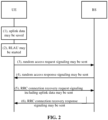
- FIG. 2 is a diagram of a scene of a method for transmitting data according to an embodiment.
- the method for transmitting data may apply to UE.
- the method for transmitting data may include steps 110-130 as follows.
- step 110 when uplink data to be transmitted to a base station are detected, the uplink data are saved in a designated buffer.
- UE is in an inactive state.
- the UE When uplink data to be transmitted to a base station are detected, the UE first saves the uplink data in the designated buffer. Then, the uplink data are transmitted to the base station along with request signaling corresponding to Radio Access Network Location Area Update (RLAU) when the UE starts the RLAU.
- the designated buffer may be a buffer of the UE per se.
- step 120 when RLAU is started, the uplink data in the designated buffer are read.
- step 130 the uplink data are transmitted to the base station in request signaling corresponding to the RLAU.
- the base station may then receive the request signaling and acquire the uplink data in the request signaling.
- request signaling corresponding to RLAU may be request signaling sent by UE to a base station.
- the request signaling is random access request signaling sent by UE to a base station.
- the request signaling may be Radio Resource Control (RRC) connection recovery request signaling sent by UE to a base station.
- RRC Radio Resource Control
- an illustrative scene includes a base station and UE.
- UE transmits uplink data to a base station, for example through RRC connection recovery request signaling.
- UE having detected uplink data to be transmitted to a base station, UE first saves the uplink data in a designated buffer. Then, while starting RLAU, the UE reads the uplink data in the designated buffer. The UE transmits the uplink data to the base station through request signaling corresponding to the RLAU, thereby implementing combination of an RLAU flow with data transmission, allowing the base station to receive uplink data transmitted by UE in an inactive state, as well as improving efficiency in data transmission.
- the RLAU in step 120 may be RLAU triggered by a designated event. Alternatively, the RLAU may be triggered periodically.
- the designated event may include, but is not limited to, a situation as follows.
- UE may move from one Radio Access Network based Notification Area (RNA) to another RNA.
- RNA Radio Access Network based Notification Area
- UE may transmit uplink data by RLAU triggered by a designated event, RLAU triggered periodically, etc., thereby increasing reliability of data transmission.
- the request signaling may be RRC connection recovery request signaling, which is a mere illustration and may not be part of the invention.
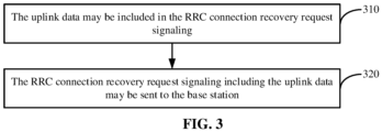
- the uplink data may be transmitted to the base station in the request signaling corresponding to the RLAU through steps 310-320 as follows.
- the uplink data may be included in the RRC connection recovery request signaling, which is a mere illustration and may not be part of the invention.
- step 320 the RRC connection recovery request signaling including the uplink data may be sent to the base station, which is a mere illustration and may not be part of the invention.
- uplink data may be included in RRC connection recovery request signaling.
- the RRC connection recovery request signaling including the uplink data may be sent to a base station, thereby diversifying modes of transmitting uplink data, increasing practicality in data transmission. This is a mere illustration which may not be part of the invention.
- the request signaling is random access request signaling.
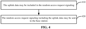
- the uplink data may be transmitted to the base station in the request signaling corresponding to the RLAU through steps 410-420 as follows.
- step 410 the uplink data is included in the random access request signaling.
- step 420 the random access request signaling including the uplink data is sent to the base station.
- uplink data are included in random access request signaling.
- the random access request signaling including the uplink data is sent to a base station, thereby diversifying modes of transmitting uplink data, increasing practicality in data transmission.
- the random access request signaling further includes RRC connection recovery request signaling.
- UE includes both uplink data and RRC connection recovery request signaling in random access request signaling, and then sends the random access request signaling to a base station.
- both uplink data and RRC connection recovery request signaling are included in random access request signaling. Then, the random access request signaling is sent to a base station, thereby simplifying an RLAU flow, as well as increasing a rate of data transmission.
- downlink data may be acquired from a response instruction sent by a base station, implementation of which may include, but is not limited to, any mode as follows.
- RRC connection recovery response signaling sent by the base station may be received.
- the RRC connection recovery response signaling may include downlink data to be transmitted to the UE by the base station. Then, the downlink data may be acquired from the RRC connection recovery response signaling.
- random response signaling sent by the base station may be received.
- the random response signaling may include downlink data to be transmitted to the UE by the base station. Then, the downlink data may be acquired from the random response signaling.
- UE may acquire the downlink data in the RRC connection recovery response signaling or the random response signaling without having to monitoring paging signaling sent by the base station, thereby diversifying modes of acquiring downlink data by UE, as well as improving efficiency in acquiring downlink data by UE.
- FIG. 5 is a flowchart of a method for transmitting data according to an embodiment.
- FIG. 6 is a diagram of a scene of a method for transmitting data according to an embodiment.
- the method for transmitting data may apply to a base station.
- the method for transmitting data may include steps 510-530 as follows.
- step 510 when downlink data to be transmitted to User Equipment (UE) are detected, the downlink data are saved in a designated buffer.
- UE User Equipment
- UE may be one in an inactive state.
- a base station may first save the downlink data in a designated buffer. Then, the downlink data may be transmitted to the UE along with response signaling corresponding to RLAU when the UE starts the RLAU.
- the designated buffer may be a buffer of the base station per se.
- step 520 when it is detected that the UE has started RLAU, the downlink data are read from the designated buffer.
- step 530 the downlink data are transmitted to the UE in response signaling corresponding to the RLAU.
- the UE may then acquire the downlink data in the response signaling.
- response signaling corresponding to RLAU may be response signaling sent to UE by a base station.
- the response signaling may be random access response signaling sent to UE by a base station .
- the response signaling may be RRC connection recovery response signaling sent to UE by a base station.
- an illustrative scene includes a base station and UE.
- the base station may transmit downlink data to the UE, for example through RRC connection recovery response signaling.
- a base station may first save the downlink data in a designated buffer. Then, when it is detected that the UE has started RLAU, the base station may read the downlink data in the designated buffer. The base station may transmit the downlink data to the UE through response signaling corresponding to the RLAU, thereby implementing combination of an RLAU flow with data transmission, allowing the base station to transmit downlink data to UE in an inactive state, as well as improving efficiency in data transmission.
- the RLAU in step 520 may be RLAU triggered by a designated event. Alternatively, the RLAU may be triggered periodically.
- the designated event may include, but is not limited to, a situation as follows.
- UE may move from one Radio Access Network based Notification Area (RNA) to another RNA.
- RNA Radio Access Network based Notification Area
- step 520 it may be detected that the UE has started RLAU, in a mode including, but not limited to, a mode as follows.
- the UE When receiving random access request signaling sent by the UE, it may be determined, according to the random access request signaling, that the UE has started the RLAU.
- downlink data may be transmitted when UE starts RLAU triggered by a designated event, RLAU triggered periodically, etc., thereby increasing reliability of data transmission.
- the response signaling may be RRC connection recovery response signaling.
- the downlink data may be transmitted to the UE in the response signaling corresponding to the RLAU through steps 710-720 as follows.
- the downlink data may be included in the RRC connection recovery response signaling.
- step 720 the RRC connection recovery response signaling including the downlink data may be sent to the UE.
- a base station may include downlink data in RRC connection recovery response signaling.
- the base station may send the RRC connection recovery response signaling including the downlink data to the UE, thereby diversifying modes of transmitting downlink data, increasing practicality in data transmission.
- the response signaling may be random access response signaling.
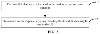
- the downlink data may be transmitted to the UE in the response signaling corresponding to the RLAU through steps 810-820 as follows.
- the downlink data may be included in the random access response signaling.
- the random access response signaling including the downlink data may be sent to the UE.
- a base station may include downlink data in random access response signaling.
- the base station may send the random access response signaling including the downlink data to the UE, increasing practicality in data transmission.
- the random access response signaling may further include RRC connection recovery response signaling.
- a base station may include both downlink data and RRC connection recovery response signaling in random access response signaling. Then, the base station may send the random access response signaling to the UE.
- a base station may include both downlink data and RRC connection recovery response signaling in random access response signaling. Then, the base station may send the random access response signaling to the UE, thereby simplifying an RLAU flow, as well as increasing a rate of data transmission.
- uplink data may be acquired from a request instruction sent by UE, implementation of which may include, but is not limited to, any mode as follows.
- the uplink data in the RRC connection recovery request signaling may be acquired. This is a mere illustration which may not be part of the invention.
- the uplink data in the random access request signaling are acquired.
- a base station acquires the uplink data in the random access request signaling and may acquire the uplink data in the RRC connection recovery request signaling, thereby diversifying modes of acquiring uplink data by a base station, as well as improving efficiency in acquiring uplink data by a base station.
- a device for transmitting data according to an embodiment herein corresponds to the method for transmitting data according to an aforementioned embodiment herein.
- FIG. 9 is a block diagram of a device for transmitting data according to an embodiment.
- the device may apply to UE.
- the device may be adapted to executing the method for transmitting data shown in FIG. 1 .
- the device for transmitting data may include an uplink data storing module, an uplink data reading module, and an uplink data sending module.
- the uplink data storing module 91 may be adapted to, in response to uplink data to be transmitted to a base station being detected, saving the uplink data in a designated buffer.
- the uplink data reading module 92 is adapted to, in response to Radio Access Network Location Area Update (RLAU) being started, reading the uplink data in the designated buffer.
- RLAU Radio Access Network Location Area Update
- UE having detected uplink data to be transmitted to a base station, UE first saves the uplink data in a designated buffer. Then, while starting RLAU, the UE reads the uplink data in the designated buffer. The UE transmits the uplink data to the base station through request signaling corresponding to the RLAU, thereby implementing combination of an RLAU flow with data transmission, allowing the base station to receive uplink data transmitted by UE in an inactive state, as well as improving efficiency in data transmission.
- the RLAU may be RLAU triggered by a designated event. Alternatively, the RLAU may be triggered periodically.
- UE may transmit uplink data by RLAU triggered by a designated event, RLAU triggered periodically, etc., thereby increasing reliability of data transmission.
- the device shown in FIG. 9 has been built.
- the request signaling may be Radio Resource Control (RRC) connection recovery request signaling, which is a mere illustration which may not be part of the invention.
- RRC Radio Resource Control
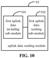
- the uplink data sending module 93 may include a first uplink data including sub-module and a first uplink data sending sub-module.
- the first uplink data including sub-module 101 may be adapted to including the uplink data in the RRC connection recovery request signaling.
- the first uplink data sending sub-module 102 may be adapted to sending, to the base station, the RRC connection recovery request signaling including the uplink data.
- uplink data may be included in RRC connection recovery request signaling.
- the RRC connection recovery request signaling including the uplink data may be sent to a base station, thereby diversifying modes of transmitting uplink data, increasing practicality in data transmission.
- the device shown in FIG. 9 has been built.
- the request signaling is random access request signaling.
- the uplink data sending module 93 may include a second uplink data including sub-module and a second uplink data sending sub-module.
- the second uplink data including sub-module 111 is adapted to including the uplink data in the random access request signaling.
- the second uplink data sending sub-module 112 is adapted to sending, to the base station, the random access request signaling including the uplink data.
- uplink data are included in random access request signaling.
- the random access request signaling including the uplink data is sent to a base station, thereby diversifying modes of transmitting uplink data, increasing practicality in data transmission.
- the random access request signaling further includes RRC connection recovery request signaling.
- both uplink data and RRC connection recovery request signaling are included in random access request signaling. Then, the random access request signaling is sent to a base station, thereby simplifying an RLAU flow, as well as increasing a rate of data transmission.
- the device shown in FIG. 9 has been built.
- the device for transmitting data may further include a downlink data acquiring module.
- the downlink data acquiring module 121 may be adapted to acquiring downlink data in RRC connection recovery response signaling, if the RRC connection recovery response signaling sent by the base station is received and the RRC connection recovery response signaling includes the downlink data to be transmitted to the UE by the base station.
- the downlink data acquiring module may be adapted to acquiring downlink data in random response signaling, if the random response signaling sent by the base station is received and the random response signaling includes the downlink data.
- UE may acquire the downlink data in the RRC connection recovery response signaling or the random response signaling without having to monitoring paging signaling sent by the base station, thereby diversifying modes of acquiring downlink data by UE, as well as improving efficiency in acquiring downlink data by UE.
- FIG. 13 is a block diagram of a device for transmitting data according to an embodiment.
- the device may apply to a base station.
- the device may be adapted to executing the method for transmitting data shown in FIG. 5 .
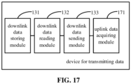
- the device for transmitting data may include a downlink data storing module, a downlink data reading module, and a downlink data sending module.
- the downlink data storing module 131 may be adapted to, in response to detecting downlink data to be transmitted to User Equipment (UE), saving the downlink data in a designated buffer.
- UE User Equipment
- the downlink data reading module 132 may be adapted to, in response to detecting that the UE has started Radio Access Network Location Area Update (RLAU), reading the downlink data in the designated buffer.
- RLAU Radio Access Network Location Area Update
- the downlink data sending module 133 may be adapted to transmitting the downlink data to the UE in response signaling corresponding to the RLAU. The UE then acquires the downlink data in the response signaling.
- a base station may first save the downlink data in a designated buffer. Then, when it is detected that the UE has started RLAU, the base station may read the downlink data in the designated buffer. The base station may transmit the downlink data to the UE through response signaling corresponding to the RLAU, thereby implementing combination of an RLAU flow with data transmission, allowing the base station to transmit downlink data to UE in an inactive state, as well as improving efficiency in data transmission.
- the device shown in FIG. 13 has been built.
- the RLAU may be RLAU triggered by a designated event. Alternatively, the RLAU may be triggered periodically.
- the downlink data reading module 132 may include a detecting sub-module and a reading sub-module.
- the detecting sub-module 141 may be adapted to, in response to receiving random access request signaling sent by the UE, determining, according to the random access request signaling, that the UE has started the RLAU.
- the reading sub-module 142 may be adapted to reading the downlink data in the designated buffer.
- downlink data may be transmitted when UE starts RLAU triggered by a designated event, RLAU triggered periodically, etc., thereby increasing reliability of data transmission.
- the device shown in FIG. 13 or FIG. 14 has been built.
- the response signaling may be RRC connection recovery response signaling.
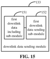
- the downlink data sending module 133 may include a first downlink data including sub-module and a first downlink data sending sub-module.
- the first downlink data including sub-module 151 may be adapted to including the downlink data in the RRC connection recovery response signaling.
- the first downlink data sending sub-module 152 may be adapted to sending, to the UE, the RRC connection recovery response signaling including the downlink data.
- a base station may include downlink data in RRC connection recovery response signaling.
- the base station may send the RRC connection recovery response signaling including the downlink data to the UE, thereby diversifying modes of transmitting downlink data, increasing practicality in data transmission.
- the device shown in FIG. 13 or FIG. 14 has been built.
- the response signaling may be random access response signaling.
- the downlink data sending module 133 may include a second downlink data including sub-module and a second downlink data sending sub-module.
- the second downlink data including sub-module 161 may be adapted to including the downlink data in the random access response signaling.
- the second downlink data sending sub-module 162 may be adapted to sending, to the UE, the random access response signaling including the downlink data.
- a base station may include downlink data in random access response signaling.
- the base station may send the random access response signaling including the downlink data to the UE, increasing practicality in data transmission.
- the random access response signaling may further include RRC connection recovery response signaling.
- a base station may include both downlink data and RRC connection recovery response signaling in random access response signaling. Then, the base station may send the random access response signaling to the UE, thereby simplifying an RLAU flow, as well as increasing a rate of data transmission.
- the device shown in FIG. 13 or FIG. 14 has been built.
- the device for transmitting data may further include an uplink data acquiring module.
- the uplink data acquiring module 171 may be adapted to, in response to receiving Radio Resource Control (RRC) connection recovery request signaling sent by the UE including uplink data to be transmitted to the base station by the UE, acquiring the uplink data in the RRC connection recovery request signaling.
- RRC Radio Resource Control
- the uplink data acquiring module may be adapted to, in response to receiving random response signaling sent by the UE including the uplink data, acquiring the uplink data in the random response signaling.
- a base station acquires the uplink data in the random access request signaling and may acquire the uplink data in the RRC connection recovery request signaling, thereby diversifying modes of acquiring uplink data by a base station, as well as improving efficiency in acquiring uplink data by a base station.
- a device embodiment herein basically corresponds to a method embodiment herein, description of which may be referred to for a related part of the device embodiment.
- a device embodiment described herein is but schematic. Units described herein as separate parts may or may not be physically separate. A part displayed as a unit may or may not be a physical unit. That is, it may be located in one place, or distributed over multiple network units. Some or all of the modules herein may be selected as needed to achieve an effect of a solution herein. A person having ordinary skill in the art may understand and implement the above without creative effort.
- a non-transitory computer-readable storing medium has stored thereon a computer program adapted to performing the method for transmitting data as shown in any one of FIG. 1 to FIG. 4 .
- a non-transitory computer-readable storing medium has stored thereon a computer program adapted to performing the method for transmitting data as shown in any one of FIG. 5 to FIG. 8 .
- a device for transmitting data may apply to UE.
- the device includes a processor and memory.
- the memory is adapted to storing an instruction executable by the processor.
- the processor is adapted to:
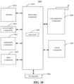
- FIG. 18 is a diagram of a structure of a device for transmitting data according to an embodiment.
- a device 1800 for transmitting data according to an embodiment is as shown in FIG. 18 .
- the device 1800 may be UE such as a computer, a mobile phone, a digital broadcast terminal, messaging equipment, a gaming console, tablet equipment, medical equipment, exercise equipment, a personal digital assistant, etc.
- the device 1800 may include at least one of a processing component 1801, memory 1802, a power supply component 1803, a multimedia component 1804, an audio component 1805, an Input / Output (I / O) interface 1806, a sensor component 1807, or a communication component 1808.
- the processing component 1801 may generally control an overall operation of the device 1800, such as operations associated with display, a telephone call, data communication, a camera operation, a recording operation, etc.
- the processing component 1801 may include one or more processors 1809 to execute instructions so as to complete all or a part of an aforementioned method.
- the processing component 1801 may include one or more modules to facilitate interaction between the processing component 1801 and other components.
- the processing component 1801 may include a multimedia portion to facilitate interaction between the multimedia component 1804 and the processing component 1801.
- the memory 1802 may be adapted to storing various types of data to support the operation at the device 1800. Examples of such data may include instructions of any application or method adapted to operating on the device 1800, contact data, phonebook data, messages, pictures, videos, etc.
- the memory 1802 may be realized by any type of transitory or non-transitory storage equipment or a combination thereof, such as Static Random Access Memory (SRAM), Electrically Erasable Programmable Read-Only Memory (EEPROM), Erasable Programmable Read-Only Memory (EPROM), Programmable Read-Only Memory (PROM), Read-Only Memory (ROM), magnetic memory, flash memory, a magnetic disk, a compact disk, etc.
- SRAM Static Random Access Memory
- EEPROM Electrically Erasable Programmable Read-Only Memory
- EPROM Erasable Programmable Read-Only Memory
- PROM Programmable Read-Only Memory
- ROM Read-Only Memory
- magnetic memory flash memory, a magnetic disk, a compact disk, etc.
- the power supply component 1803 may supply electric power to various components of the device 1800.
- the power supply component 1803 may include a power management system, one or more power sources, and other components related to generating, managing, and distributing electricity for the device 1800.
- the multimedia component 1804 may include a screen that provides an output interface between the device 1800 and a user.
- the screen may include a Liquid Crystal Display (LCD), a Touch Panel (TP), etc. If the screen includes a TP, the screen may be realized as a touch screen to receive a signal input by a user.
- the TP may include one or more touch sensors for sensing touch, slide, and gestures on the TP. The one or more touch sensors not only may sense the boundary of a touch or slide move, but also detect the duration and pressure related to the touch or slide move.
- the multimedia component 1804 may include at least one of a front camera or a rear camera.
- At least one of the front camera or the rear camera may receive external multimedia data.
- Each of the front camera or the rear camera may be a fixed optical lens system or may have a focal length and be capable of optical zooming.
- the audio component 1805 may be adapted to outputting and / or inputting an audio signal.
- the audio component 1805 may include a microphone (MIC).
- the MIC When the device 1800 is in an operation mode such as a call mode, a recording mode, a voice recognition mode, etc., the MIC may be adapted to receiving an external audio signal.
- the received audio signal may be further stored in the memory 1802 or may be sent via the communication component 1808.
- the audio component 1805 may further include a loudspeaker adapted to outputting the audio signal.
- the I / O interface 1806 may provide an interface between the processing component 1801 and a peripheral interface portion.
- a peripheral interface portion may be a keypad, a click wheel, a button, etc.
- a button may include but is not limited to at least one of a homepage button, a volume button, a start button, or a lock button.
- the sensor component 1807 may include one or more sensors for assessing various states of the device 1800. For example, the sensor component 1807 may detect an on/off state of the device 1800 and relative positioning of components such as the display and the keypad of the device 1800. The sensor component 1807 may further detect a change in the position of the device 1800 or of a component of the device 1800, whether there is contact between the device 1800 and a user, the orientation or acceleration / deceleration of the device 1800, a change in the temperature of the device 1800, etc.
- the sensor component 1807 may include a proximity sensor adapted to detecting existence of a nearby object without physical contact.
- the sensor component 1807 may further include an optical sensor such as a Complementary Metal-Oxide-Semiconductor (CMOS) or a Charge-Coupled-Device (CCD) image sensor used in an imaging application.
- CMOS Complementary Metal-Oxide-Semiconductor
- CCD Charge-Coupled-Device
- the sensor component 1807 may further include an acceleration sensor, a gyroscope sensor, a magnetic sensor, a pressure sensor, a temperature sensor, etc.
- the communication component 1808 may be adapted to facilitating wired or wireless communication between the device 1800 and other equipment.
- the device 1800 may access a wireless network based on a communication standard such as Wi-Fi, 2G, 3G..., or a combination thereof.
- the communication component 1808 may broadcast related information or receive a broadcast signal from an external broadcast management system via a broadcast channel.
- the communication component 1808 may include a Near Field Communication (NFC) module for short-range communication.
- the NFC module may be based on technology such as Radio Frequency Identification (RFID), Infrared Data Association (IrDA), Ultra-Wideband (UWB) technology, Bluetooth (BT), etc.
- RFID Radio Frequency Identification
- IrDA Infrared Data Association
- UWB Ultra-Wideband
- Bluetooth Bluetooth
- the device 1800 may be realized by one or more electronic components such as an Application Specific Integrated Circuit (ASIC), a Digital Signal Processor (DSP), a Digital Signal Processing Device (DSPD), a Programmable Logic Device (PLD), a Field Programmable Gate Array (FPGA), a controller, a microcontroller, a microprocessor, etc., to implement the method.
- ASIC Application Specific Integrated Circuit
- DSP Digital Signal Processor
- DSPD Digital Signal Processing Device
- PLD Programmable Logic Device
- FPGA Field Programmable Gate Array
- controller a microcontroller, a microprocessor, etc.
- an instruction in the storage medium causes the device 1800 to perform at least part of any aforementioned method for transmitting data.
- a device for transmitting data may apply to a base station.
- the device includes a processor and memory.
- the memory is adapted to storing an instruction executable by the processor.
- the processor is adapted to:
- FIG. 19 is a diagram of a structure of a device for transmitting data according to an embodiment.
- the device 1900 as shown in FIG. 19 may be provided as a base station.
- the device 1900 includes a processing component 1922, a radio transmitting/receiving component 1924, an antenna component 1926, and a signal processing part dedicated to a radio interface.
- the processing component 1922 may further include one or more processors.
- a processor of the processing component 1922 may be adapted to performing any aforementioned method for connecting a network.
Landscapes
- Engineering & Computer Science (AREA)
- Signal Processing (AREA)
- Computer Networks & Wireless Communication (AREA)
- Mobile Radio Communication Systems (AREA)
Claims (10)
- Verfahren zum Übertragen von Daten, umfassend:als Reaktion auf das Erfassen von Uplink-Daten, die an eine Basisstation (1900) übertragen werden sollen, Speichern der Uplink-Daten durch das Endgerät, UE (1800), in einem inaktiven Zustand in einem ausgewiesenen Puffer (110);als Reaktion auf das Starten des Radio Access Network Location Area Update, RLAU, Lesen der Uplink-Daten im ausgewiesenen Puffer (120) durch das UE (1800); undÜbertragen der Uplink-Daten durch das UE (1800) an die Basisstation (1900) in einer Anforderungssignalisierung, die dem RLAU entspricht, so dass die Basisstation (1900) die Uplink-Daten in der Anforderungssignalisierung (130) erhebt,wobei die Anforderungssignalisierung eine Zufallszugriffsanforderungssignalisierung ist,wobei das Übertragen der Uplink-Daten an die Basisstation (1900) in einer dem RLAU entsprechenden Anforderungssignalisierung Folgendes umfasst:Einschließen der Uplink-Daten durch das UE (1800) in die Zufallszugriffsanforderungssignalisierung (410); undSenden der Zufallszugriffsanforderungssignalisierung einschließlich der Uplink-Daten (420) durch das UE (1800) an die Basisstation (1900),dadurch gekennzeichnet, dass die Zufallszugriffsanforderungssignalisierung weiter eine Radio-Resource-Control-, RRC-, Verbindungswiederherstellungs-Anforderungssignalisierung umfasst.
- Verfahren nach Anspruch 1, wobei das RLAU RLAU umfasst, das durch ein ausgewiesenes Ereignis ausgelöst wird, und RLAU, das periodisch ausgelöst wird.
- Verfahren nach Anspruch 1 oder 2, weiter umfassend:als Reaktion auf das Empfangen einer von der Basisstation (1900) gesendeten Radio-Resource-Control-, RRC-, Verbindungswiederherstellungs-Antwortsignalisierung, die Downlink-Daten einschließt, die von der Basisstation (1900) an das UE (1800) zu übertragen sind, Erheben der Downlink-Daten in der RRC-Verbindungswiederherstellungs-Antwortsignalisierung durch das UE (1800); oderals Reaktion auf den Empfang einer von der Basisstation (1900) gesendeten Zufallsantwortsignalisierung, die die Downlink-Daten einschließt, Erheben der Downlink-Daten in der Zufallsantwortsignalisierung durch das UE (1800).
- Verfahren nach einem der Ansprüche 1 bis 3, weiter umfassend:
Empfangen durch die Basisstation (1900), der Uplink-Daten, die von dem UE (1800) in der Zufallszugriffsanforderungssignalisierung übertragen werden. - Verfahren nach Anspruch 4, weiter umfassend:als Reaktion auf das Erfassen von Downlink-Daten, die an das UE (1800) übertragen werden sollen, Speichern der Downlink-Daten durch die Basisstation (1900) in einem zweiten ausgewiesenen Puffer (510);als Reaktion auf das Erfassen, dass das UE (1800) das RLAU gestartet hat, Lesen der Downlink-Daten in dem zweiten ausgewiesenen Puffer (520) durch die Basisstation (1900); undÜbertragen der Downlink-Daten durch die Basisstation (1900) an das UE (1800) in einer dem RLAU entsprechenden Antwortsignalisierung derart, dass das UE (1800) die Downlink-Daten in der Antwortsignalisierung (530) erhebt.
- Verfahren nach Anspruch 5, wobei das RLAU RLAU umfasst, das durch ein ausgewiesenes Ereignis ausgelöst wird, und RLAU, das periodisch ausgelöst wird,
wobei das Erfassen, dass das UE (1800) das RLAU gestartet hat, Folgendes umfasst:
als Reaktion auf den Empfang der von dem UE (1800) gesendeten Zufallszugriffsanforderungssignalisierung, Bestimmen durch die Basisstation (1900) gemäß der Zufallszugriffsanforderungssignalisierung, dass das UE (1800) das RLAU gestartet hat. - Verfahren nach Anspruch 5 oder 6, wobei die Antwortsignalisierung eine Radio-Resource-Control-, RRC-, Verbindungswiederherstellungs-Antwortsignalisierung ist,
wobei das Übertragen der Downlink-Daten an das UE (1800) in der dem RLAU entsprechenden Antwortsignalisierung Folgendes umfasst:Einschließen der Downlink-Daten durch die Basisstation (1900) in die RRC-Verbindungswiederherstellungs-Antwortsignalisierung; undSenden der RRC-Verbindungswiederherstellungs-Antwortsignalisierung einschließlich der Downlink-Daten durch die Basisstation (1900) an das UE (1800). - Verfahren nach Anspruch 5 oder 6, wobei die Antwortsignalisierung eine Zufallszugriffsantwortsignalisierung ist,
wobei das Übertragen der Downlink-Daten an das UE (1800) in der dem RLAU entsprechenden Antwortsignalisierung Folgendes umfasst:Einschließen der Downlink-Daten in die Zufallszugriffsantwortsignalisierung (810) durch die Basisstation (1900); undSenden der Zufallszugriffsantwortsignalisierung einschließlich der Downlink-Daten (820) durch die Basisstation (1900) an das UE (1800). - Verfahren nach Anspruch 8, wobei die Zufallszugriffsantwortsignalisierung weiter eine Radio-Resource-Control-, RRC-, Verbindungswiederherstellungs-Antwortsignalisierung umfasst.
- Vorrichtung zum Übertragen von Daten, beispielsweise Endgerät, UE (1800), wobei die Vorrichtung einen Prozessor (1809) und einen Speicher (1802) umfasst,wobei der Speicher (1802) dazu angepasst ist, eine Anweisung zu speichern, die von dem Prozessor (1809) ausführbar ist,wobei der Prozessor (1809) dazu angepasst ist, das Verfahren nach einem der Ansprüche 1 bis 3 auszuführen.
Applications Claiming Priority (1)
| Application Number | Priority Date | Filing Date | Title |
|---|---|---|---|
| PCT/CN2017/105661 WO2019071462A1 (zh) | 2017-10-11 | 2017-10-11 | 数据传输方法及装置 |
Publications (3)
| Publication Number | Publication Date |
|---|---|
| EP3694236A1 EP3694236A1 (de) | 2020-08-12 |
| EP3694236A4 EP3694236A4 (de) | 2021-05-05 |
| EP3694236B1 true EP3694236B1 (de) | 2025-02-12 |
Family
ID=65533135
Family Applications (1)
| Application Number | Title | Priority Date | Filing Date |
|---|---|---|---|
| EP17928539.0A Active EP3694236B1 (de) | 2017-10-11 | 2017-10-11 | Verfahren und vorrichtung zur datenübertragung |
Country Status (4)
| Country | Link |
|---|---|
| US (1) | US11265924B2 (de) |
| EP (1) | EP3694236B1 (de) |
| CN (1) | CN109451857B (de) |
| WO (1) | WO2019071462A1 (de) |
Families Citing this family (2)
| Publication number | Priority date | Publication date | Assignee | Title |
|---|---|---|---|---|
| JP7097445B2 (ja) * | 2018-02-14 | 2022-07-07 | オッポ広東移動通信有限公司 | 通信方法、ネットワークデバイス及び端末デバイス |
| WO2023076102A1 (en) * | 2021-10-27 | 2023-05-04 | Kyocera Corporation | Coded slotted access based random-access scheme |
Family Cites Families (24)
| Publication number | Priority date | Publication date | Assignee | Title |
|---|---|---|---|---|
| KR100606757B1 (ko) * | 2003-05-30 | 2006-07-31 | 엘지전자 주식회사 | 무선망을 이용한 단말기의 실행코드 업데이트 방법 |
| EP1617606A1 (de) * | 2004-07-16 | 2006-01-18 | Matsushita Electric Industrial Co., Ltd. | Modenumschaltungsplanung für Aufwärtsübertragungen |
| CN102100114B (zh) * | 2009-09-30 | 2013-12-04 | 华为技术有限公司 | 一种移动性管理的方法和终端设备 |
| CN106028273B (zh) | 2010-03-23 | 2020-01-14 | Iot控股公司 | 用于机器类型通信的方法及wtru |
| CN102457825A (zh) * | 2010-10-15 | 2012-05-16 | 电信科学技术研究院 | 一种数据的传输方法和设备 |
| WO2012048915A1 (en) | 2010-10-15 | 2012-04-19 | Telefonaktiebolaget L M Ericsson (Publ) | Lightweight data transmission mechanism |
| KR101752985B1 (ko) * | 2012-10-04 | 2017-07-03 | 닛본 덴끼 가부시끼가이샤 | 무선 액세스 네트워크 장치, 코어 네트워크 장치, 이동 단말, 이들의 방법, 및 컴퓨터 판독가능 매체 |
| CN103781124B (zh) * | 2012-10-26 | 2016-12-28 | 电信科学技术研究院 | 一种上行数据传输方法及用户设备 |
| EP2983384B1 (de) * | 2013-04-23 | 2019-04-10 | Huawei Technologies Co., Ltd. | Datenpaketübertragungsverfahren und vorrichtung |
| CN104333908B (zh) * | 2013-07-22 | 2019-01-04 | 电信科学技术研究院 | 数据传输方法、系统和设备 |
| CN106162705B (zh) * | 2015-03-31 | 2020-02-04 | 电信科学技术研究院 | 一种控制用户面承载建立的方法及设备 |
| US10231089B2 (en) * | 2015-06-23 | 2019-03-12 | Lg Electronics Inc. | Method for managing area of terminal in wireless communication system and apparatus therefor |
| WO2017133678A1 (zh) * | 2016-02-05 | 2017-08-10 | 中兴通讯股份有限公司 | 终端与网络间连接处理方法和装置 |
| CN106131886A (zh) * | 2016-06-21 | 2016-11-16 | 北京小米移动软件有限公司 | 数据传输方法及装置 |
| KR20180035638A (ko) * | 2016-09-29 | 2018-04-06 | 삼성전자주식회사 | RRC Inactive 및 active 상태에서 data 전송 결정 및 방법 및 장치 |
| EP3902368B1 (de) * | 2016-09-30 | 2023-05-03 | Samsung Electronics Co., Ltd. | Verfahren und vorrichtung zur einrichtung von dualer konnektivität zur übertragung von daten in einer new-radio-funkkommunikationsarchitektur |
| KR102685320B1 (ko) * | 2017-02-10 | 2024-07-17 | 삼성전자 주식회사 | 이동 통신 시스템에서 다중연결을 사용한 핸드오버 시 보안키를 처리하는 방법 및 장치 |
| ES2914398T3 (es) * | 2017-02-12 | 2022-06-10 | Fg innovation co ltd | Gestión de movilidad para equipos de usuario RRC_INACTIVO |
| CN106879076B (zh) * | 2017-04-14 | 2020-07-14 | 中国联合网络通信集团有限公司 | 一种数据传输的方法及装置 |
| WO2019004692A1 (en) * | 2017-06-27 | 2019-01-03 | Lg Electronics Inc. | METHOD FOR IMPLEMENTING A RLEAU PROCEDURE AND DEVICE SUPPORTING SAID METHOD |
| KR102163867B1 (ko) * | 2017-06-28 | 2020-10-12 | 에스케이텔레콤 주식회사 | 단말장치 및 업링크 데이터 전송 방법 |
| TWI711331B (zh) * | 2017-08-11 | 2020-11-21 | 聯發科技股份有限公司 | 用於物聯網之使用者設備自動釋放之方法及其裝置 |
| EP3681242A4 (de) * | 2017-09-21 | 2020-09-23 | Beijing Xiaomi Mobile Software Co., Ltd. | Verfahren und vorrichtung zur netzwerkverbindung |
| CN209372087U (zh) * | 2019-03-07 | 2019-09-10 | 上海崇越航空科技有限公司 | 一种转盘式航空计算尺 |
-
2017
- 2017-10-11 EP EP17928539.0A patent/EP3694236B1/de active Active
- 2017-10-11 WO PCT/CN2017/105661 patent/WO2019071462A1/zh not_active Ceased
- 2017-10-11 CN CN201780001626.6A patent/CN109451857B/zh active Active
-
2020
- 2020-04-08 US US16/843,465 patent/US11265924B2/en active Active
Also Published As
| Publication number | Publication date |
|---|---|
| US20200236720A1 (en) | 2020-07-23 |
| US11265924B2 (en) | 2022-03-01 |
| CN109451857B (zh) | 2023-06-23 |
| CN109451857A (zh) | 2019-03-08 |
| EP3694236A1 (de) | 2020-08-12 |
| EP3694236A4 (de) | 2021-05-05 |
| WO2019071462A1 (zh) | 2019-04-18 |
Similar Documents
| Publication | Publication Date | Title |
|---|---|---|
| US12238650B2 (en) | Bandwidth part switching method and apparatus | |
| EP3866517B1 (de) | Verfahren und vorrichtungen zur überwachung eines energiesparsignals | |
| EP3771261B1 (de) | Funkrufsynchronisationsanzeigeverfahren und -vorrichtung, funkrufsynchronisationsverfahren sowie vorrichtung und basisstation | |
| US10063760B2 (en) | Photographing control methods and devices | |
| US10694572B2 (en) | Methods and devices for controlling states of user equipment | |
| CN107018496B (zh) | 寻呼方法及装置 | |
| US11711864B2 (en) | Network connection method and device | |
| US11178637B2 (en) | Paging message receiving method and device, and paging configuration method and device | |
| CN109496445B (zh) | 非连续接收配置方法及装置 | |
| US11968665B2 (en) | Resource configuration methods and apparatuses | |
| JP2017531978A (ja) | 撮影制御方法、装置、プログラム、及び記録媒体 | |
| EP3905804A1 (de) | Verfahren und vorrichtung zur direktverbindungsressourcenkonfiguration | |
| EP3565374B1 (de) | Regionskonfigurationsverfahren und -vorrichtungen | |
| US10348540B2 (en) | Communication method and apparatus, and storage medium | |
| CN110771196A (zh) | Mdt信息通知方法和装置、mdt信息接收方法和装置 | |
| US12089101B2 (en) | Cell handover method and apparatus, handover configuration method and apparatus, and user equipment | |
| EP3793245A1 (de) | Verfahren und vorrichtung zur übertragung von präambel- und planungsanforderungen | |
| US11606684B2 (en) | Method and device for resolving dual subscriber identity module paging conflict | |
| US11177867B2 (en) | Beam reporting and adjusting method and apparatus, user equipment, and base station | |
| US11265924B2 (en) | Method and device for data transmission | |
| WO2019028856A1 (zh) | 寻呼指示方法及装置 | |
| EP3654709B1 (de) | Verfahren und vorrichtung zur anzeige der übertragungsrichtung | |
| EP3962175A1 (de) | Zellrekonfigurationsverfahren und -vorrichtung | |
| US20240314732A1 (en) | Method and apparatus for determining user paging group, and user equipment and storage medium | |
| EP3621359B1 (de) | Verfahren und vorrichtung für empfang und übertragung eines downlink-steuerkanals |
Legal Events
| Date | Code | Title | Description |
|---|---|---|---|
| STAA | Information on the status of an ep patent application or granted ep patent |
Free format text: STATUS: THE INTERNATIONAL PUBLICATION HAS BEEN MADE |
|
| PUAI | Public reference made under article 153(3) epc to a published international application that has entered the european phase |
Free format text: ORIGINAL CODE: 0009012 |
|
| STAA | Information on the status of an ep patent application or granted ep patent |
Free format text: STATUS: REQUEST FOR EXAMINATION WAS MADE |
|
| 17P | Request for examination filed |
Effective date: 20200507 |
|
| AK | Designated contracting states |
Kind code of ref document: A1 Designated state(s): AL AT BE BG CH CY CZ DE DK EE ES FI FR GB GR HR HU IE IS IT LI LT LU LV MC MK MT NL NO PL PT RO RS SE SI SK SM TR |
|
| AX | Request for extension of the european patent |
Extension state: BA ME |
|
| DAV | Request for validation of the european patent (deleted) | ||
| DAX | Request for extension of the european patent (deleted) | ||
| A4 | Supplementary search report drawn up and despatched |
Effective date: 20210407 |
|
| RIC1 | Information provided on ipc code assigned before grant |
Ipc: H04W 4/20 20180101AFI20210330BHEP Ipc: H04W 28/02 20090101ALI20210330BHEP Ipc: H04W 60/00 20090101ALI20210330BHEP Ipc: H04W 60/02 20090101ALI20210330BHEP Ipc: H04W 60/04 20090101ALI20210330BHEP Ipc: H04W 76/27 20180101ALN20210330BHEP |
|
| STAA | Information on the status of an ep patent application or granted ep patent |
Free format text: STATUS: EXAMINATION IS IN PROGRESS |
|
| 17Q | First examination report despatched |
Effective date: 20230213 |
|
| REG | Reference to a national code |
Ref country code: DE Free format text: PREVIOUS MAIN CLASS: H04W0004200000 Ref country code: DE Ref legal event code: R079 Ref document number: 602017087779 Country of ref document: DE Free format text: PREVIOUS MAIN CLASS: H04W0004200000 Ipc: H04W0028020000 |
|
| GRAP | Despatch of communication of intention to grant a patent |
Free format text: ORIGINAL CODE: EPIDOSNIGR1 |
|
| STAA | Information on the status of an ep patent application or granted ep patent |
Free format text: STATUS: GRANT OF PATENT IS INTENDED |
|
| RIC1 | Information provided on ipc code assigned before grant |
Ipc: H04W 74/08 20090101ALN20241128BHEP Ipc: H04W 60/04 20090101ALN20241128BHEP Ipc: H04W 60/02 20090101ALN20241128BHEP Ipc: H04W 76/27 20180101ALN20241128BHEP Ipc: H04W 74/0833 20240101ALI20241128BHEP Ipc: H04L 5/00 20060101ALI20241128BHEP Ipc: H04W 28/02 20090101AFI20241128BHEP |
|
| GRAS | Grant fee paid |
Free format text: ORIGINAL CODE: EPIDOSNIGR3 |
|
| INTG | Intention to grant announced |
Effective date: 20241210 |
|
| GRAA | (expected) grant |
Free format text: ORIGINAL CODE: 0009210 |
|
| STAA | Information on the status of an ep patent application or granted ep patent |
Free format text: STATUS: THE PATENT HAS BEEN GRANTED |
|
| AK | Designated contracting states |
Kind code of ref document: B1 Designated state(s): AL AT BE BG CH CY CZ DE DK EE ES FI FR GB GR HR HU IE IS IT LI LT LU LV MC MK MT NL NO PL PT RO RS SE SI SK SM TR |
|
| REG | Reference to a national code |
Ref country code: GB Ref legal event code: FG4D |
|
| REG | Reference to a national code |
Ref country code: CH Ref legal event code: EP |
|
| REG | Reference to a national code |
Ref country code: DE Ref legal event code: R096 Ref document number: 602017087779 Country of ref document: DE |
|
| REG | Reference to a national code |
Ref country code: IE Ref legal event code: FG4D Ref country code: NL Ref legal event code: FP |
|
| P01 | Opt-out of the competence of the unified patent court (upc) registered |
Free format text: CASE NUMBER: APP_8617/2025 Effective date: 20250220 |
|
| PG25 | Lapsed in a contracting state [announced via postgrant information from national office to epo] |
Ref country code: RS Free format text: LAPSE BECAUSE OF FAILURE TO SUBMIT A TRANSLATION OF THE DESCRIPTION OR TO PAY THE FEE WITHIN THE PRESCRIBED TIME-LIMIT Effective date: 20250512 |
|
| PG25 | Lapsed in a contracting state [announced via postgrant information from national office to epo] |
Ref country code: FI Free format text: LAPSE BECAUSE OF FAILURE TO SUBMIT A TRANSLATION OF THE DESCRIPTION OR TO PAY THE FEE WITHIN THE PRESCRIBED TIME-LIMIT Effective date: 20250212 |
|
| PG25 | Lapsed in a contracting state [announced via postgrant information from national office to epo] |
Ref country code: PL Free format text: LAPSE BECAUSE OF FAILURE TO SUBMIT A TRANSLATION OF THE DESCRIPTION OR TO PAY THE FEE WITHIN THE PRESCRIBED TIME-LIMIT Effective date: 20250212 |
|
| PG25 | Lapsed in a contracting state [announced via postgrant information from national office to epo] |
Ref country code: ES Free format text: LAPSE BECAUSE OF FAILURE TO SUBMIT A TRANSLATION OF THE DESCRIPTION OR TO PAY THE FEE WITHIN THE PRESCRIBED TIME-LIMIT Effective date: 20250212 |
|
| REG | Reference to a national code |
Ref country code: LT Ref legal event code: MG9D |
|
| PG25 | Lapsed in a contracting state [announced via postgrant information from national office to epo] |
Ref country code: IS Free format text: LAPSE BECAUSE OF FAILURE TO SUBMIT A TRANSLATION OF THE DESCRIPTION OR TO PAY THE FEE WITHIN THE PRESCRIBED TIME-LIMIT Effective date: 20250612 Ref country code: NO Free format text: LAPSE BECAUSE OF FAILURE TO SUBMIT A TRANSLATION OF THE DESCRIPTION OR TO PAY THE FEE WITHIN THE PRESCRIBED TIME-LIMIT Effective date: 20250512 |
|
| PG25 | Lapsed in a contracting state [announced via postgrant information from national office to epo] |
Ref country code: HR Free format text: LAPSE BECAUSE OF FAILURE TO SUBMIT A TRANSLATION OF THE DESCRIPTION OR TO PAY THE FEE WITHIN THE PRESCRIBED TIME-LIMIT Effective date: 20250212 |
|
| PG25 | Lapsed in a contracting state [announced via postgrant information from national office to epo] |
Ref country code: PT Free format text: LAPSE BECAUSE OF FAILURE TO SUBMIT A TRANSLATION OF THE DESCRIPTION OR TO PAY THE FEE WITHIN THE PRESCRIBED TIME-LIMIT Effective date: 20250612 Ref country code: LV Free format text: LAPSE BECAUSE OF FAILURE TO SUBMIT A TRANSLATION OF THE DESCRIPTION OR TO PAY THE FEE WITHIN THE PRESCRIBED TIME-LIMIT Effective date: 20250212 |
|
| PG25 | Lapsed in a contracting state [announced via postgrant information from national office to epo] |
Ref country code: BG Free format text: LAPSE BECAUSE OF FAILURE TO SUBMIT A TRANSLATION OF THE DESCRIPTION OR TO PAY THE FEE WITHIN THE PRESCRIBED TIME-LIMIT Effective date: 20250212 Ref country code: GR Free format text: LAPSE BECAUSE OF FAILURE TO SUBMIT A TRANSLATION OF THE DESCRIPTION OR TO PAY THE FEE WITHIN THE PRESCRIBED TIME-LIMIT Effective date: 20250513 |
|
| REG | Reference to a national code |
Ref country code: AT Ref legal event code: MK05 Ref document number: 1767268 Country of ref document: AT Kind code of ref document: T Effective date: 20250212 |
|
| PG25 | Lapsed in a contracting state [announced via postgrant information from national office to epo] |
Ref country code: SE Free format text: LAPSE BECAUSE OF FAILURE TO SUBMIT A TRANSLATION OF THE DESCRIPTION OR TO PAY THE FEE WITHIN THE PRESCRIBED TIME-LIMIT Effective date: 20250212 |
|
| PG25 | Lapsed in a contracting state [announced via postgrant information from national office to epo] |
Ref country code: SM Free format text: LAPSE BECAUSE OF FAILURE TO SUBMIT A TRANSLATION OF THE DESCRIPTION OR TO PAY THE FEE WITHIN THE PRESCRIBED TIME-LIMIT Effective date: 20250212 |
|
| PG25 | Lapsed in a contracting state [announced via postgrant information from national office to epo] |
Ref country code: DK Free format text: LAPSE BECAUSE OF FAILURE TO SUBMIT A TRANSLATION OF THE DESCRIPTION OR TO PAY THE FEE WITHIN THE PRESCRIBED TIME-LIMIT Effective date: 20250212 |
|
| PG25 | Lapsed in a contracting state [announced via postgrant information from national office to epo] |
Ref country code: AT Free format text: LAPSE BECAUSE OF FAILURE TO SUBMIT A TRANSLATION OF THE DESCRIPTION OR TO PAY THE FEE WITHIN THE PRESCRIBED TIME-LIMIT Effective date: 20250212 |
|
| PG25 | Lapsed in a contracting state [announced via postgrant information from national office to epo] |
Ref country code: CZ Free format text: LAPSE BECAUSE OF FAILURE TO SUBMIT A TRANSLATION OF THE DESCRIPTION OR TO PAY THE FEE WITHIN THE PRESCRIBED TIME-LIMIT Effective date: 20250212 Ref country code: EE Free format text: LAPSE BECAUSE OF FAILURE TO SUBMIT A TRANSLATION OF THE DESCRIPTION OR TO PAY THE FEE WITHIN THE PRESCRIBED TIME-LIMIT Effective date: 20250212 |
|
| PG25 | Lapsed in a contracting state [announced via postgrant information from national office to epo] |
Ref country code: RO Free format text: LAPSE BECAUSE OF FAILURE TO SUBMIT A TRANSLATION OF THE DESCRIPTION OR TO PAY THE FEE WITHIN THE PRESCRIBED TIME-LIMIT Effective date: 20250212 |
|
| PG25 | Lapsed in a contracting state [announced via postgrant information from national office to epo] |
Ref country code: SK Free format text: LAPSE BECAUSE OF FAILURE TO SUBMIT A TRANSLATION OF THE DESCRIPTION OR TO PAY THE FEE WITHIN THE PRESCRIBED TIME-LIMIT Effective date: 20250212 |
|
| REG | Reference to a national code |
Ref country code: DE Ref legal event code: R097 Ref document number: 602017087779 Country of ref document: DE |
|
| PGFP | Annual fee paid to national office [announced via postgrant information from national office to epo] |
Ref country code: NL Payment date: 20251021 Year of fee payment: 9 |
|
| PLBE | No opposition filed within time limit |
Free format text: ORIGINAL CODE: 0009261 |
|
| STAA | Information on the status of an ep patent application or granted ep patent |
Free format text: STATUS: NO OPPOSITION FILED WITHIN TIME LIMIT |
|
| PGFP | Annual fee paid to national office [announced via postgrant information from national office to epo] |
Ref country code: DE Payment date: 20251021 Year of fee payment: 9 |
|
| PGFP | Annual fee paid to national office [announced via postgrant information from national office to epo] |
Ref country code: GB Payment date: 20251022 Year of fee payment: 9 |
|
| PGFP | Annual fee paid to national office [announced via postgrant information from national office to epo] |
Ref country code: IT Payment date: 20251024 Year of fee payment: 9 |
|
| PGFP | Annual fee paid to national office [announced via postgrant information from national office to epo] |
Ref country code: FR Payment date: 20251030 Year of fee payment: 9 |
|
| 26N | No opposition filed |
Effective date: 20251113 |