EP3695183B1 - Anordnung zur speicherung von thermischer energie - Google Patents
Anordnung zur speicherung von thermischer energie Download PDFInfo
- Publication number
- EP3695183B1 EP3695183B1 EP18810897.1A EP18810897A EP3695183B1 EP 3695183 B1 EP3695183 B1 EP 3695183B1 EP 18810897 A EP18810897 A EP 18810897A EP 3695183 B1 EP3695183 B1 EP 3695183B1
- Authority
- EP
- European Patent Office
- Prior art keywords
- heat
- fus
- manner
- mesh
- arrangement according
- Prior art date
- Legal status (The legal status is an assumption and is not a legal conclusion. Google has not performed a legal analysis and makes no representation as to the accuracy of the status listed.)
- Active
Links
Images


Classifications
-
- F—MECHANICAL ENGINEERING; LIGHTING; HEATING; WEAPONS; BLASTING
- F28—HEAT EXCHANGE IN GENERAL
- F28D—HEAT-EXCHANGE APPARATUS, NOT PROVIDED FOR IN ANOTHER SUBCLASS, IN WHICH THE HEAT-EXCHANGE MEDIA DO NOT COME INTO DIRECT CONTACT
- F28D20/00—Heat storage plants or apparatus in general; Regenerative heat-exchange apparatus not covered by groups F28D17/00 or F28D19/00
- F28D20/0056—Heat storage plants or apparatus in general; Regenerative heat-exchange apparatus not covered by groups F28D17/00 or F28D19/00 using solid heat storage material
-
- F—MECHANICAL ENGINEERING; LIGHTING; HEATING; WEAPONS; BLASTING
- F28—HEAT EXCHANGE IN GENERAL
- F28D—HEAT-EXCHANGE APPARATUS, NOT PROVIDED FOR IN ANOTHER SUBCLASS, IN WHICH THE HEAT-EXCHANGE MEDIA DO NOT COME INTO DIRECT CONTACT
- F28D20/00—Heat storage plants or apparatus in general; Regenerative heat-exchange apparatus not covered by groups F28D17/00 or F28D19/00
- F28D2020/0065—Details, e.g. particular heat storage tanks, auxiliary members within tanks
- F28D2020/0086—Partitions
- F28D2020/0091—Partitions flexible
-
- Y—GENERAL TAGGING OF NEW TECHNOLOGICAL DEVELOPMENTS; GENERAL TAGGING OF CROSS-SECTIONAL TECHNOLOGIES SPANNING OVER SEVERAL SECTIONS OF THE IPC; TECHNICAL SUBJECTS COVERED BY FORMER USPC CROSS-REFERENCE ART COLLECTIONS [XRACs] AND DIGESTS
- Y02—TECHNOLOGIES OR APPLICATIONS FOR MITIGATION OR ADAPTATION AGAINST CLIMATE CHANGE
- Y02E—REDUCTION OF GREENHOUSE GAS [GHG] EMISSIONS, RELATED TO ENERGY GENERATION, TRANSMISSION OR DISTRIBUTION
- Y02E60/00—Enabling technologies; Technologies with a potential or indirect contribution to GHG emissions mitigation
- Y02E60/14—Thermal energy storage
Definitions
- the invention relates to an arrangement for storing thermal energy.
- renewable energy Wind energy, solar energy, tidal energy, etc.
- Heat accumulators are known in which solid materials are used as storage material - for example stones or ceramics or rubble.
- a heated fluid - for example electrically heated air - is used as a heat transfer medium and introduced into the heat accumulator.
- the solid storage material of the heat accumulator is heated up and used for temporary energy storage.
- a (cool) fluid such as air is blown into the heat accumulator, heated therein and then fed to a converter system.
- the converter system converts the thermal energy taken from the heat accumulator via the fluid (air) into electrical energy.
- the extracted thermal energy is converted into electrical energy via a steam cycle and using a steam turbine.
- a highly efficient, competitive energy storage system must guarantee high steam parameters (temperature T, power P). This can only be achieved if thermal energy is stored using high temperatures. The material used for storage is therefore exposed to high and possibly rapid temperature differences and must therefore withstand corresponding loads (e.g. thermal or mechanical loads).
- the material used for storage is to be insulated or sealed with a fluid-impermeable, flexible layer from the environment of the heat accumulator.
- a fluid-impermeable, flexible layer from the environment of the heat accumulator.
- an airtight film is used for this purpose, which is arranged in such a way that the pressure or temperature within the heat accumulator is maintained.
- This fluid-impermeable, flexible layer is exposed to the same high and possibly rapid temperature differences due to the close contact with the material used for storage and must therefore also be able to withstand the corresponding loads.
- this fluid-impermeable, flexible layer must ensure that the entire volume of the heat accumulator used in the working mode is retained in order to avoid unwanted effects in the heat accumulator (e.g. uneven temperature distribution in the storage volume or the formation of undesired channels inside the heat accumulator or its material) to prevent.
- FIG 7 shows a cross section of a heat storage WSP which is constructed according to the prior art.
- the heat storage WSP contains a solid natural material MAT for heat storage.
- the heat storage material MAT is encompassed by a fluid-impermeable, flexible layer FUS, a film, in such a way that the heat storage material MAT is at least pressure-tightly insulated with regard to the surroundings of the heat storage device or in relation to the surroundings of the heat storage device.
- the heat storage material MAT is supported within the heat storage WSP in the lower and middle area by a shaping base structure BST, which can contain vermiculite or Yton, for example.
- a shaping base structure BST which can contain vermiculite or Yton, for example.
- the heat storage material MAT is encompassed within the heat storage WSP in the upper area by an insulation DMG which is arranged between the heat storage material MAT and the fluid-impermeable, flexible layer FUS.
- an insulation DMG which is arranged between the heat storage material MAT and the fluid-impermeable, flexible layer FUS.
- Pamphlet WO 2017/055475 A1 discloses several cover layers, including an impermeable cover sheet, which can probably compensate for changes in size due to settling processes of the thermal material.
- Pamphlet DE 27 21 173 A1 also shows an underground reserve in which a film is provided. However, the film seems to be firmly connected from the inside to a heat insulating layer provided, without compensatory movements being provided.
- the arrangement comprises a three-dimensionally designed heat accumulator which contains a solid natural material for heat storage.
- the heat storage material is encompassed by a fluid-impermeable, flexible layer in such a way that the heat storage material is at least pressure-tightly insulated with a view to the surroundings of the heat storage device or in relation to the surroundings of the heat storage device.
- a flexible cover layer which applies a surface force to the fluid-impermeable, flexible layer.
- the fluid-impermeable, flexible layer is thereby pressed flatly and preferably in a form-fitting manner onto the heat storage material.
- the flexible cover layer is firstly in the form of a network or secondly in the form of sheet metal panels that overlap in a scale-like manner.
- the solid natural material used to store heat is also known as heat storage material.
- the fluid-impermeable, flexible layer is always in close contact with the material used for heat storage in an optimized manner.
- the volume of the heat storage material or the total volume of the heat storage is retained. This prevents unwanted effects in the heat storage (e.g. uneven temperature distribution in the storage volume or the formation of undesirable channels inside the heat storage or its material).
- a fluid for example air is used to transfer thermal energy to the heat storage material and to extract thermal energy from the heat storage material.
- the heat accumulator has at least one input and at least one output, via which the fluid is passed for energy storage and for energy extraction.
- heated fluid is introduced into the heat storage via the inlet for energy storage.
- thermal energy is transferred from the fluid to the heat storage material.
- the cooler fluid is led out of the heat accumulator via the outlet.
- cooler fluid for energy extraction is introduced into the heat storage via the inlet.
- thermal energy is transferred from the heat storage material to the fluid and the fluid, which is now hotter, is conducted out of the heat storage via the outlet.
- the fluid which is richer in energy than the heat storage, is introduced into the heat storage via at least one inlet opening and guided therein in such a way that the heat storage material is heated by the fluid. With the help of the heat storage material, the thermal energy supplied via the fluid is stored.
- the fluid which is correspondingly lower in energy or cooler after storage, is led out of the heat store via the at least one outlet opening.
- fluid that is cooler or less energetic than the storage material is introduced into the heat accumulator via at least one inlet opening and guided therein in such a way that the heat accumulator material heats the fluid.
- thermal energy is supplied to the fluid.
- the fluid which is correspondingly richer in energy after the energy has been extracted, is led out of the heat accumulator via at least one outlet opening.
- FIG 1 shows a cross section of a first embodiment of a heat accumulator WSP1 according to the invention in a basic representation - the in FIG 6
- the shaping basic structure BST shown and the insulation DMG are not shown in detail here or in the following figures, but can be attached to the appropriate places are provided or arranged.
- the heat storage WSP1 contains a solid natural material MAT for heat storage.
- the heat storage material MAT is encompassed by a fluid-impermeable, flexible layer FUS, here by way of example a film, in such a way that the heat storage material MAT is at least pressure-tightly insulated with a view to the environment of the heat storage device WSP1.
- a flexible cover layer FDS1 in the form of a network which applies a surface force F network to the film FUS.
- the network is indicated here as a broken line above the film FUS.
- the film FUS is pressed flatly and preferably in a form-fitting manner onto the heat storage material MAT by means of the network.
- the network can be a metallic network, ie preferably made of metal.
- a network is to be understood as a meshed system of fibers, ropes or wires.
- the meshed system contains connection points at which the fibers, ropes or wires are interlaced with one another.
- a network is a flat structure in which forces are well distributed. Between the fibers, ropes or wires that form meshes are voids or openings.
- the meshes or openings can be designed, for example, rhombic, square or hexagonal .
- the fibers, ropes or wires are preferably connected to one another in a sliding and / or knotless manner at their connection points. In this way, different forces can be balanced, so that the network nevertheless forms a uniform, uniform surface, without bulges or indentations.
- the net is preferably designed with such a close-meshed structure that the film cannot pass through mesh openings.
- FIG 2 shows with reference to FIG 1 another embodiment of the invention.
- a network FDS2 is not pressed onto the film FUS with the aid of a layer of sand, but with the aid of an anchoring system (not shown here, for example by means of tension belts, etc.).
- the film FUS is additionally shaped (for example, in the shape of a bulge) in order to be able to compensate for forces F p that act. Accordingly, the film FUS is free of the network FDS2 in this area.
- FIG 3 shows with reference to FIG 1 another embodiment of the invention.
- a network FDS3 is not pressed onto the foil FUS with the aid of a layer of sand, but with the aid of hydraulic cylinders HYD.
- respective position points POS can be seen at which respective hydraulic cylinders HYD are arranged in order to exert vertically aligned forces on the film FUS with one end of the hydraulic cylinder HYD.
- the hydraulic cylinders HYD are fastened with their other end to a fastening device (for example to a ceiling of the heat accumulator WSP3).
- FIG 4 shows with reference to FIG 3 an alternative embodiment of the invention in a slight modification.
- a network FDS4 is not pressed onto the film FUS with the aid of hydraulic cylinders, but with the help of a movable cover DEK of the heat accumulator WSP4.
- the ceiling slides along the raised side edges of the heat accumulator WSP4, whereby a corresponding weight of the ceiling DEK is increased via tensioning ropes SPS.
- the position of the ceiling DEK in relation to the film FUS and the required surface force are defined using the tensioning cables SPS and with the help of pre-formed, defined spacers ABS.
- FIG 5 shows with reference to FIG 1 an alternative embodiment of the invention in a further cross section.
- the heat storage WSP5 contains a solid natural material MAT for heat storage.
- the heat storage material MAT is comprised of a fluid-impermeable, flexible layer FUS, here by way of example a film, in such a way that the heat storage material MAT - preferably with a view to the environment of the heat storage WSP5 or in relation to the surroundings of the heat storage WSP5 - is at least insulated in a pressure-tight manner.
- an at least partially flexible cover layer FDS5 in the form of scale armor is provided here, which has sheet metal panels that overlap in a scale-like manner - cf. in this regard that in FIG FIG 5 shown detail.
- the film FUS is thus pressed flatly and preferably in a form-fitting manner onto the heat storage material MAT.
- pull ropes ZS are placed in respective pipes over the scales of the top layer FDS5 relocated. These tension ropes ZS are in turn tensioned via tension ropes SPS so that the sheet-metal panels FDS5, which overlap in a scale-like manner, press on the foil FUS.
- FIG 6 shows with reference to FIG 3 another embodiment of the invention.
- a gas-tight network structure FDS6 is pressed onto the film FUS with the aid of gas pressure.
- the heat accumulator WSP6 has a gas-tight cover DEK6.
- FIG 7 also shows the cross-section of a heat accumulator described in the introduction, which is constructed according to the prior art.
Landscapes
- Engineering & Computer Science (AREA)
- Physics & Mathematics (AREA)
- Thermal Sciences (AREA)
- Mechanical Engineering (AREA)
- General Engineering & Computer Science (AREA)
- Building Environments (AREA)
- Thermotherapy And Cooling Therapy Devices (AREA)
Description
- Die Erfindung betrifft eine Anordnung zur Speicherung von thermischer Energie.
- Bei einem hohen Anteil an erneuerbarer Energie (Windenergie, Sonnenenergie, Gezeitenenergie, etc.) in einem Energieversorgungsnetz wird es zunehmend wichtiger, die erneuerbare Energie zwischenzuspeichern, um die Verfügbarkeit der erneuerbaren Energie mit den Erfordernissen der Netzstabilität und dem Verbraucherverhalten sinnvoll zu kombinieren.
- Es ist bekannt, gewonnene elektrische Energie in thermische Energie (Hitze) umzuwandeln und in einem Wärmespeicher zeitlich begrenzt zwischenzuspeichern.
- Es sind Wärmespeicher bekannt, bei denen feste Materialien als Speichermaterial verwendet werden - beispielsweise Steine oder Keramik bzw. Geröll. Ein erhitztes Fluid - zum Beispiel elektrisch aufgeheizte Luft - wird als Hitze-Übertragungsmedium verwendet und in den Wärmespeicher eingeleitet. Das feste Speichermaterial des Wärmespeichers wird aufgeheizt und zur zeitlichen Energiespeicherung verwendet.
- Entsprechend wird bei einer Energieentnahme aus dem Wärmespeicher ein (kühles) Fluid wie Luft in den Wärmespeicher geblasen, darin aufgeheizt und nachfolgend einem Wandlersystem zugeführt. Das Wandlersystem wandelt die aus dem Wärmespeicher über das Fluid (Luft) entnommene thermische Energie in elektrische Energie um.
- Beispielsweise wird mit Hilfe der erhitzen Luft die entnommene thermische Energie über einen Wasserdampf-Kreislauf und unter Verwendung einer Dampfturbine in elektrische Energie umgewandelt.
- Ein Wettbewerb-fähiges Energiespeichersystem hoher Effizienz muss hohe Dampfparameter (Temperatur T, Leistung P) gewährleisten. Dies kann nur erreicht werden, wenn thermische Energie unter Verwendung hoher Temperaturen gespeichert wird. Das zur Speicherung verwendete Material ist somit hohen und ggf. schnell erfolgenden Temperaturunterschieden ausgesetzt und muss damit einhergehend entsprechenden Belastungen (z.B. thermischen bzw. mechanischen Belastungen) widerstehen.
- Es ist bekannt, dass zur Speicherung verwendete Material mit einer Fluid-undurchlässigen, flexiblen Schicht gegenüber der Umwelt des Wärmespeichers zu isolieren bzw. abzudichten. Beispielsweise kommt zu diesem Zweck eine luftdichte Folie zum Einsatz, die derart angeordnet ist, dass Druck bzw. Temperatur innerhalb des Wärmespeichers erhalten bleiben.
- Diese Fluid-undurchlässige, flexible Schicht wird durch den engen Kontakt mit dem zur Speicherung verwendeten Material den gleichen hohen und ggf. schnell erfolgenden Temperaturunterschieden ausgesetzt und muss damit einhergehend den entsprechenden Belastungen ebenfalls widerstehen können.
- Zugleich muss diese Fluid-undurchlässige, flexible Schicht gewährleisten, dass das im Arbeitsmodus verwendete gesamte Volumen des Wärmespeichers erhalten bleibt, um ungewollte Effekte im Wärmespeicher (z.B. eine ungleichmäßige Temperaturverteilung im Speichervolumen oder die Bildung von unerwünschten Kanälen im Inneren des Wärmespeichers bzw. dessen Materials) zu verhindern.
- Aufgrund der geforderten Funktion der Fluid-undurchlässigen Schicht muss mit Blick auf die Flexibilität sichergestellt werden, dass die Fluid-undurchlässige Schicht im Betrieb und damit unter Einwirkung von hohem Druck bzw. Temperatur dicht bleibt.
- Wie oben angesprochen muss auch sichergestellt werden, dass die Fluid-undurchlässige Schicht im engen Kontakt mit dem zur Speicherung verwendeten Material bleibt.
-
FIG 7 zeigt einen Querschnitt eines Wärmespeicher WSP, der gemäß dem Stand der Technik aufgebaut ist. Der Wärmespeicher WSP beinhaltet ein festes natürliches Material MAT zur Wärmespeicherung. Das Wärmespeicher-Material MAT ist von einer Fluid-undurchlässigen, flexiblen Schicht FUS, einer Folie, derart umfasst, dass das Wärmespeicher-Material MAT mit Blick auf die Umwelt des Wärmespeichers bzw. in Beziehung zur Umgebung des Wärmespeichers zumindest druckdicht isoliert ist. - Das Wärmespeicher-Material MAT ist innerhalb des Wärmespeichers WSP im unteren und im mittleren Bereich von einer formgebenden Basisstruktur BST gestützt, die beispielsweise Vermiculit oder Yton enthalten kann. Mit Hilfe der formgebenden Basisstruktur BST wird die Form und das Volumen des Wärmespeicher-Materials MAT im Wesentlichen definiert und damit die Wärmeaufnahme, die Wärmeabgabe sowie die Temperaturausbreitung im Inneren des Wärmespeichers WSP mit festgelegt.
- Das Wärmespeicher-Material MAT ist innerhalb des Wärmespeichers WSP im oberen Bereich umfasst von einer Dämmung DMG, die zwischen dem Wärmespeicher-Material MAT und der Fluid-undurchlässigen, flexiblen Schicht FUS angeordnet ist. Mit Hilfe der Dämmung DMG wird einerseits ein enger Kontakt zwischen der Schicht FUS und dem Wärmespeicher-Material MAT hergestellt, andererseits wird durch die Dämmung DMG eine Beschädigung der Schicht FUS durch das Wärmespeicher-Material MAT vermieden.
- Druckschrift
WO 2017/055475 A1 offenbart mehrere Deckschichten, darunter auch eine undurchlässige Deckfolie, die wohl Größenänderungen aufgrund Setzvorgänge des Wärmematerials ausgleichen kann. - Druckschrift
DE 27 21 173 A1 zeigt außerdem ein Untergrundreservior, bei dem eine Folie vorgesehen ist. Die Folie scheint allerdings fest von innen mit einer vorgesehenen Wärmeisolierschicht verbunden zu sein, ohne dass Ausgleichsbewegungen vorgesehen sind. - Es ist die Aufgabe der vorliegenden Erfindung, einen bezüglich der Fluid-undurchlässigen Schicht optimierten Wärmespeicher anzugeben.
- Diese Aufgabe der Erfindung wird durch die Merkmale des Anspruchs 1 gelöst.
- Vorteilhafte Weiterbildungen der Erfindung sind in den abhängigen Ansprüchen angegeben.
- Es wird eine Anordnung zur Speicherung von thermischer Energie beansprucht. Die Anordnung umfasst einen räumlich ausgestalteten Wärmespeicher, der ein festes natürliches Material zur Wärmespeicherung beinhaltet. Das Wärmespeicher-Material ist von einer Fluid-undurchlässigen, flexiblen Schicht derart umfasst, dass das Wärmespeicher-Material mit Blick auf die Umwelt des Wärmespeichers bzw. in Beziehung zur Umgebung des Wärmespeichers zumindest druckdicht isoliert ist.
- Erfindungsgemäß ist eine flexible Deckschicht vorgesehen, die auf die Fluid-undurchlässige, flexible Schicht eine Flächenkraft aufbringt. Die Fluid-undurchlässige, flexible Schicht wird dadurch flächig und bevorzugt formschlüssig auf das Wärmespeicher-Material aufgedrückt.
- Die flexible Deckschicht weist erstens die Form eines Netzes auf oder ist zweitens in Form von schuppenartig überlappenden Blechtafeln ausgebildet.
- Das feste natürliche Material zur Wärmespeicherung wird auch als Wärmespeicher-Material bezeichnet.
- Mit Hilfe der vorliegenden Erfindung wird vorteilhaft erreicht, dass trotz benötigter hoher Dampfparameter (Temperatur T, Leistung P) die Fluid-undurchlässige, flexible Schicht stets optimiert im engen Kontakt mit dem zur Wärmespeicherung verwendeten Material steht.
- Auch bei hohen und ggf. schnell erfolgenden Temperaturunterschieden bleibt das Volumen des Wärmespeichermaterials bzw. das Gesamtvolumen des Wärmespeichers erhalten. Dadurch werden ungewollte Effekte im Wärmespeicher (z.B. eine ungleichmäßige Temperaturverteilung im Speichervolumen oder die Bildung von unerwünschten Kanälen im Inneren des Wärmespeichers bzw. dessen Materials) verhindert.
- Zur Übertragung von thermischer Energie an das Wärmespeichermaterial und zur Entnahme von thermischer Energie aus dem Wärmespeichermaterial wird ein Fluid (beispielsweise Luft) verwendet. Der Wärmespeicher weist zumindest einen Eingang und zumindest einen Ausgang auf, über die das Fluid zur Energiespeicherung und zur Energieentnahme geleitet wird. Im Vergleich zur Temperatur des Wärmespeichermaterials heißeres, erhitztes Fluid wird zur Energiespeicherung über den Eingang in den Wärmespeicher eingeleitet. Dort wird thermische Energie vom Fluid an das Wärmespeichermaterial übertragen. Das kühlere Fluid wird über den Ausgang aus dem Wärmespeicher geleitet. Entsprechend wird - im Vergleich zur Temperatur des Wärmespeichermaterials - kühleres Fluid zur Energieentnahme über den Eingang in den Wärmespeicher eingeleitet. Dort wird thermische Energie vom Wärmespeichermaterial an das Fluid übertragen und das jetzt heißere Fluid wird über den Ausgang aus dem Wärmespeicher geleitet.
- Bei der Energiespeicherung wird das im Vergleich zum Wärmespeicher Energie-reichere Fluid über zumindest eine Eingangsöffnung in den Wärmespeicher eingeleitet und darin derart geführt, dass das Wärmespeicher-Material durch das Fluid erhitzt wird. Mit Hilfe des Wärmespeicher-Materials wird also die über das Fluid zugeführte thermische Energie gespeichert.
- Das nach der Speicherung entsprechend Energie-ärmere bzw. kühlere Fluid wird über die zumindest eine Ausgangsöffnung aus dem Wärmespeicher geführt.
- Bei der Energieentnahme wird im Vergleich zum Speichermaterial kühleres bzw. energieärmeres Fluid über zumindest eine Eingangsöffnung in den Wärmespeicher eingeleitet und darin derart geführt, dass das Wärmespeicher-Material das Fluid erhitzt. Mit Hilfe des Wärmespeicher-Materials wird also dem Fluid thermische Energie zugeführt. Das nach der Energieentnahme entsprechend Energie-reichere Fluid wird über zumindest eine Ausgangsöffnung aus dem Wärmespeicher geführt.
- Nachfolgend wird die vorliegende Erfindung anhand von Figuren näher erläutert. Dabei zeigt:
- FIG 1
- einen Querschnitt eines erfindungsgemäßen Wärmespeichers in einer prinzipiellen Darstellung,
- FIG 2
- mit Bezug auf
FIG 1 eine weitere Ausgestaltung der Erfindung, - FIG 3
- mit Bezug auf
FIG 1 eine weitere Ausgestaltung der Erfindung - FIG 4
- mit Bezug auf
FIG 3 eine alternative Ausgestaltung der Erfindung, - FIG 5
- mit Bezug auf
FIG 1 eine alternative Ausgestaltung der Erfindung, - FIG 6
- mit Bezug auf
FIG 3 eine weitere Ausgestaltung der Erfindung, und - FIG 7
- den in der Einleitung beschriebenen Querschnitt eines Wärmespeichers, der gemäß dem Stand der Technik aufgebaut ist.
-
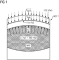
FIG 1 zeigt einen Querschnitt einer erste Ausgestaltung eines erfindungsgemäßen Wärmespeichers WSP1 in einer prinzipiellen Darstellung - die inFIG 6 gezeigte formgebende Basisstruktur BST sowie die Dämmung DMG sind hier und in den nachfolgenden Figuren nicht detailliert dargestellt, können jedoch an den entsprechenden Stellen vorgesehen sein bzw. angeordnet werden. - Der Wärmespeicher WSP1 beinhaltet ein festes natürliches Material MAT zur Wärmespeicherung. Das Wärmespeicher-Material MAT ist von einer Fluid-undurchlässigen, flexiblen Schicht FUS, hier beispielhaft einer Folie, derart umfasst, dass das Wärmespeicher-Material MAT mit Blick auf die Umwelt des Wärmespeichers WSP1 zumindest druckdicht isoliert ist.
- Dadurch stellt sich im Betrieb beispielsweise im Inneren des Wärmespeichers WSP1 ein Druck von 200 mbar ein, der über resultierende Kräfte Fp flächig gleichmäßig verteilt letztlich auf die Folie FUS wirkt.
- Erfindungsgemäß ist eine flexible Deckschicht FDS1 in Form eines Netzes vorgesehen, die auf die Folie FUS eine Flächenkraft FNetz aufbringt. Das Netz ist hier als unterbrochene Linie oberhalb der Folie FUS angedeutet. Die Folie FUS wird mittels des Netzes flächig und bevorzugt formschlüssig auf das Wärmespeichermaterial MAT aufgedrückt.
- Zur Erzeugung der Flächenkraft FNetz wird beispielswiese eine Schicht aus Sand auf das Netz aufgebracht, so dass über das Eigengewicht des Sandes eine Flächenkraft FSand = FNetz gebildet wird.
- Alternativ oder ergänzend dazu könnte das Netz auch aus entsprechend schwerem Material (Metall) gefertigt sein, um eine entsprechende Gewichtskraft FGewicht = FNetz zu bilden. Somit kann das Netz ein metallisches Netz sein, d.h. vorzugsweise aus Metall gefertigt sein.
- Unter Netz ist ein vermaschtes System von Fasern, Seilen oder Drähten zu verstehen. Das vermaschte System enthält Verknüpfungspunkte, an denen die Fasern, Seile oder Drähte miteinander verschränkt sind. Ein Netz ist ein flächiges Gebilde, in dem Kräfte gut verteilt werden. Zwischen den Fasern, Seilen oder Drähten, die Maschen bilden, sind Leerräume bzw. Öffnungen. Die Maschen bzw. Öffnungen können beispielsweise rhombisch, quadratisch oder sechseckig ausgebildet sein. Vorzugsweise sind die Fasern, Seile oder Drähte an ihren Verknüpfungspunkten gleitend und/oder knotenlos miteinander verknüpfte. Auf diese Weise können unterschiedliche Kräfte ausgeglichen werden, so dass das Netz trotzdem eine einheitliche gleichförmige Fläche ausbildet, ohne Aus- oder Einstülpungen.
- Das Netz ist vorzugsweise derart engmaschig ausgebildet, dass die Folie nicht durch Maschenöffnungen treten kann.
-
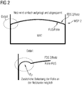
FIG 2 zeigt mit Bezug aufFIG 1 eine weitere Ausgestaltung der Erfindung. Bei dem hier gezeigten Wärmespeicher WSP2 wird ein Netz FDS2 nicht mit Hilfe einer Sandschicht, sondern mit Hilfe einer Abspannung (hier nicht näher dargestellt, z.B. mittels Spanngurten, etc.) auf die Folie FUS gepresst. - Im Detail wird eine bevorzugte Ausgestaltung der Kontaktsituation zwischen der Folie FUS und dem überhöhten Rand des Wärmespeicher WSP2 dargestellt. In diesem Übergangsbereich ist die Folie FUS zusätzlich (z.B. beulenförmig) ausgeformt, um einwirkende Kräfte Fp kompensieren zu können. Entsprechend ist die Folie FUS in diesem Bereich frei vom Netz FDS2.
-
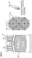
FIG 3 zeigt mit Bezug aufFIG 1 eine weitere Ausgestaltung der Erfindung. Bei dem hier gezeigten Wärmespeicher WSP3 wird ein Netz FDS3 nicht mit Hilfe einer Sandschicht, sondern mit Hilfe von Hydraulikzylindern HYD auf die Folie FUS gepresst. - In der Draufsicht sind jeweilige Positionspunkte POS zu sehen, an denen jeweilige Hydraulikzylindern HYD angeordnet sind, um vertikal ausgerichtete Kräfte auf die Folie FUS mit einem Ende des Hydraulikzylinders HYD auszuüben. Entsprechend sind zu diesem Zweck die Hydraulikzylinder HYD mit ihrem anderen Ende an einer Befestigungseinrichtung (z.B. an einer Decke des Wärmespeicher WSP3) befestigt.
-
FIG 4 zeigt mit Bezug aufFIG 3 eine alternative Ausgestaltung der Erfindung in einer leichten Abwandlung. - Bei dem hier gezeigten Wärmespeicher WSP4 wird ein Netz FDS4 nicht mit Hilfe von Hydraulikzylindern, sondern mit Hilfe einer beweglichen Decke DEK des Wärmespeicher WSP4 auf die Folie FUS gepresst.
- Die Decke gleitet an überhöhten Seitenrändern des Wärmespeicher WSP4 entlang, wobei eine entsprechende Gewichtskraft der Decke DEK über Spannseile SPS erhöht wird.
- Über die Spannseile SPS und mit Hilfe von vorgeformten, definierten Abstandshaltern ABS wird die Position der Decke DEK in Bezug auf die Folie FUS sowie die benötigte Flächenkraft definiert.
-
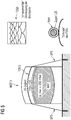
FIG 5 zeigt mit Bezug aufFIG 1 eine alternative Ausgestaltung der Erfindung in einem weiteren Querschnitt. - Der Wärmespeicher WSP5 beinhaltet ein festes natürliches Material MAT zur Wärmespeicherung. Das Wärmespeicher-Material MAT ist von einer Fluid-undurchlässigen, flexiblen Schicht FUS, hier beispielhaft einer Folie, derart umfasst, dass das Wärmespeicher-Material MAT - vorzugsweise mit Blick auf die Umwelt des Wärmespeichers WSP5 bzw. in Beziehung zur Umgebung des Wärmespeichers WSP5 - zumindest druckdicht isoliert ist.
- Erfindungsgemäß ist hier eine Schuppenpanzer-förmige, zumindest teil-flexible Deckschicht FDS5 vorgesehen, die schuppenartig überlappende Blechtafeln aufweist - vgl. hierzu das in
FIG 5 gezeigte Detail. - Die Folie FUS wird damit flächig und bevorzugt formschlüssig auf das Wärmespeichermaterial MAT aufgedrückt.
- Zur Erzeugung der benötigten Flächenkraft werden Zugseile ZS in jeweiligen Rohren über die Schuppen der Deckschicht FDS5 verlegt. Diese Zugseile ZS werden wiederum über Spannseile SPS angespannt, so dass die schuppenartig überlappenden Blechtafeln FDS5 auf die Folie FUS drücken.
-
FIG 6 zeigt mit Bezug aufFIG 3 eine weitere Ausgestaltung der Erfindung. Bei dem hier gezeigten Wärmespeicher WSP6 wird eine Gas-dichte Netzstruktur FDS6 mit Hilfe von Gasdruck auf die Folie FUS gepresst. - In dieser Ausgestaltung weist der Wärmespeicher WSP6 eine Gas-dichte Decke DEK6 auf.
-
FIG 7 zeigt weiterhin den in der Einleitung beschriebenen Querschnitt eines Wärmespeichers, der gemäß dem Stand der Technik aufgebaut ist.
Claims (9)
- Anordnung zur Speicherung von thermischer Energie,- mit einem räumlich ausgestalteten Wärmespeicher, der ein festes natürliches Material zur Wärmespeicherung beinhaltet, nämlich ein Wärmespeicher-Material (MAT),- bei dem das Wärmespeicher-Material (MAT) von einer Fluid-undurchlässigen, flexiblen Schicht (FUS) derart umfasst ist, dass das Wärmespeicher-Material (MAT) mit Blick auf die Umwelt des Wärmespeichers zumindest druckdicht isoliert ist,dadurch gekennzeichnet,- dass eine flexible Deckschicht vorgesehen ist, die mit der Fluid-undurchlässigen flexiblen Schicht (FUS) derart gekoppelt ist, dass die flexible Deckschicht eine Flächenkraft auf die Fluid-undurchlässige, flexible Schicht (FUS) aufbringt, so dass die Fluid-undurchlässige flexible Schicht (FUS) flächig auf das Wärmespeicher-Material (MAT) drückt, und- dass die flexible Deckschicht (i) die Form eines Netzes aufweist oder (ii) in Form von schuppenartig überlappenden Blechtafeln (FDS5) ausgebildet ist.
- Anordnung nach Anspruch 1, dadurch gekennzeichnet, dass die Fluid-undurchlässige flexible Schicht (FUS) eine Folie ist.
- Anordnung nach Anspruch 1 oder 2, dadurch gekennzeichnet, dass, sofern die flexible Deckschicht die Form eines Netzes aufweist, das Netz als metallisches Netz ausgebildet ist.
- Anordnung nach Anspruch 3, dadurch gekennzeichnet, dass zur Erzeugung der Flächenkraft eine Schicht aus Sand auf das Netz derart aufgebracht ist, um das Netz auf die Folie zu drücken.
- Anordnung nach Anspruch 1 bis 3, dadurch gekennzeichnet, dass zur Erzeugung der Flächenkraft das Netz und/oder die schuppenartig überlappenden Blechtafeln (FDS5) aus schwerem Material, insbesondere aus Metall, gefertigt ist.
- Anordnung nach Anspruch 1 bis 3, dadurch gekennzeichnet, dass zur Erzeugung der Flächenkraft Spanngurte derart vorgesehen sind, dass das Netz und/oder die schuppenartig überlappenden Blechtafeln (FDS5) mit Hilfe der Spanngurten auf die Fluid-undurchlässige flexible Schicht (FUS) gepresst wird.
- Anordnung nach Anspruch 1 bis 3, dadurch gekennzeichnet, dass zur Erzeugung der Flächenkraft Hydraulikzylindern derart vorgesehen sind, dass das Netz mit Hilfe der Hydraulikzylindern auf die Fluid-undurchlässige flexible Schicht (FUS) gepresst wird.
- Anordnung nach Anspruch 1 bis 3, dadurch gekennzeichnet, dass zur Erzeugung der Flächenkraft die Decke des Wärmespeichers derart beweglich ausgestaltet ist, dass die bewegliche Decke auf die Fluid-undurchlässige flexible Schicht (FUS) gepresst wird.
- Anordnung nach Anspruch 1 oder 2, dadurch gekennzeichnet, dass, sofern schuppenartig überlappenden Blechtafeln (FDS5) vorhanden sind, in jeweiligen Rohren verlaufende Zugseile (ZS) über die schuppenartig überlappenden Blechtafeln angeordnet sind.
Applications Claiming Priority (2)
| Application Number | Priority Date | Filing Date | Title |
|---|---|---|---|
| EP17202011.7A EP3486594A1 (de) | 2017-11-16 | 2017-11-16 | Anordnung zur speicherung von thermischer energie |
| PCT/EP2018/081142 WO2019096809A1 (de) | 2017-11-16 | 2018-11-14 | Anordnung zur speicherung von thermischer energie |
Publications (2)
| Publication Number | Publication Date |
|---|---|
| EP3695183A1 EP3695183A1 (de) | 2020-08-19 |
| EP3695183B1 true EP3695183B1 (de) | 2021-07-14 |
Family
ID=60387864
Family Applications (2)
| Application Number | Title | Priority Date | Filing Date |
|---|---|---|---|
| EP17202011.7A Withdrawn EP3486594A1 (de) | 2017-11-16 | 2017-11-16 | Anordnung zur speicherung von thermischer energie |
| EP18810897.1A Active EP3695183B1 (de) | 2017-11-16 | 2018-11-14 | Anordnung zur speicherung von thermischer energie |
Family Applications Before (1)
| Application Number | Title | Priority Date | Filing Date |
|---|---|---|---|
| EP17202011.7A Withdrawn EP3486594A1 (de) | 2017-11-16 | 2017-11-16 | Anordnung zur speicherung von thermischer energie |
Country Status (5)
| Country | Link |
|---|---|
| US (1) | US11486654B2 (de) |
| EP (2) | EP3486594A1 (de) |
| CN (1) | CN111656122B (de) |
| DK (1) | DK3695183T3 (de) |
| WO (1) | WO2019096809A1 (de) |
Families Citing this family (13)
| Publication number | Priority date | Publication date | Assignee | Title |
|---|---|---|---|---|
| US12291982B2 (en) | 2020-11-30 | 2025-05-06 | Rondo Energy, Inc. | Thermal energy storage systems for use in material processing |
| US12359591B1 (en) | 2020-11-30 | 2025-07-15 | Rondo Energy, Inc. | Thermal energy storage systems for repowering existing power plants for improving efficiency and safety |
| US12018596B2 (en) | 2020-11-30 | 2024-06-25 | Rondo Energy, Inc. | Thermal energy storage system coupled with thermal power cycle systems |
| IL303311B2 (en) | 2020-11-30 | 2025-11-01 | Rondo Energy Inc | Energy storage system and applications |
| US11913362B2 (en) | 2020-11-30 | 2024-02-27 | Rondo Energy, Inc. | Thermal energy storage system coupled with steam cracking system |
| US12146424B2 (en) | 2020-11-30 | 2024-11-19 | Rondo Energy, Inc. | Thermal energy storage system coupled with a solid oxide electrolysis system |
| US11913361B2 (en) | 2020-11-30 | 2024-02-27 | Rondo Energy, Inc. | Energy storage system and alumina calcination applications |
| EP4174430A1 (de) * | 2021-11-02 | 2023-05-03 | Siemens Gamesa Renewable Energy GmbH & Co. KG | Thermische energiespeichervorrichtung mit überdruckschutz |
| WO2024215949A2 (en) | 2023-04-14 | 2024-10-17 | Rondo Energy, Inc. | Thermal energy storage systems with improved seismic stability |
| US12480719B2 (en) | 2024-04-24 | 2025-11-25 | Rondo Energy, Inc. | Thermal energy storage system for simple and combined cycle power generation |
| US12595973B2 (en) | 2024-05-24 | 2026-04-07 | Rondo Energy, Inc. | Thermal energy storage system with high efficiency heater control |
| US12566034B1 (en) | 2024-07-02 | 2026-03-03 | Rondo Energy, Inc. | Thermal energy storage system coupled to a heat exchanger with thermal protection |
| US12607170B2 (en) | 2024-07-12 | 2026-04-21 | Rondo Energy, Inc. | Thermal energy storage system for use with a low temperature heat source and a thermal power cycle system |
Family Cites Families (11)
| Publication number | Priority date | Publication date | Assignee | Title |
|---|---|---|---|---|
| US3949527A (en) * | 1974-08-09 | 1976-04-13 | Canamer Leasing Services Inc. | Material supported cover and method for securing said cover to the ground |
| DE2721173A1 (de) * | 1977-05-11 | 1978-11-16 | Franz Kerner | Waermespeicher |
| DE2949584A1 (de) * | 1979-12-10 | 1981-06-11 | Herbert Ing.(grad.) 5000 Köln Kaniut | Erd-waermespeicher und erdwaerme-kollektor mit erhoehter leistung |
| DE3124021C2 (de) * | 1981-06-19 | 1985-02-14 | Dornier System Gmbh, 7990 Friedrichshafen | Wärmespeicher für eine Heizungsanlage |
| US4897970A (en) * | 1988-08-18 | 1990-02-06 | Canamer International, Inc. | Method of covering and securing material |
| US6994156B2 (en) * | 2001-04-20 | 2006-02-07 | Coolsmart Llc | Air-conditioning system with thermal storage |
| KR101645912B1 (ko) | 2008-02-22 | 2016-08-04 | 다우 글로벌 테크놀로지스 엘엘씨 | 열 저장 장치 |
| CN101303207B (zh) * | 2008-06-24 | 2010-06-09 | 上海第二工业大学 | 可移动冷热源模块 |
| CA2804806C (en) * | 2010-07-14 | 2018-10-30 | Bright Energy Storage Technologies, Llp | System and method for storing thermal energy |
| WO2016150462A1 (en) * | 2015-03-20 | 2016-09-29 | Siemens Aktiengesellschaft | Thermal energy storage with increased capacity |
| EP3311093A1 (de) * | 2015-09-30 | 2018-04-25 | Siemens Aktiengesellschaft | Wärmeaustauschsystem mit einer wärmeaustauschkammer in einem bodenaushub, verfahren zur herstellung des wärmeaustauschsystems und verfahren zum wärmetausch anhand des wärmeaustauschsystems |
-
2017
- 2017-11-16 EP EP17202011.7A patent/EP3486594A1/de not_active Withdrawn
-
2018
- 2018-11-14 CN CN201880074229.6A patent/CN111656122B/zh not_active Expired - Fee Related
- 2018-11-14 EP EP18810897.1A patent/EP3695183B1/de active Active
- 2018-11-14 US US16/763,162 patent/US11486654B2/en active Active
- 2018-11-14 DK DK18810897.1T patent/DK3695183T3/da active
- 2018-11-14 WO PCT/EP2018/081142 patent/WO2019096809A1/de not_active Ceased
Also Published As
| Publication number | Publication date |
|---|---|
| EP3486594A1 (de) | 2019-05-22 |
| DK3695183T3 (da) | 2021-09-06 |
| CN111656122A (zh) | 2020-09-11 |
| WO2019096809A1 (de) | 2019-05-23 |
| US11486654B2 (en) | 2022-11-01 |
| US20200278157A1 (en) | 2020-09-03 |
| CN111656122B (zh) | 2022-01-14 |
| EP3695183A1 (de) | 2020-08-19 |
Similar Documents
| Publication | Publication Date | Title |
|---|---|---|
| EP3695183B1 (de) | Anordnung zur speicherung von thermischer energie | |
| EP2764215B1 (de) | Energiespeichervorrichtung mit offenem ladekreislauf zur speicherung saisonal anfallender elektrischer überschussenergie | |
| EP2286168B1 (de) | Vorrichtung zum speichern von thermischer energie | |
| EP2764216A2 (de) | Hochtemperatur-energiespeicher mit rekuperator | |
| EP2739919A1 (de) | Energiespeichervorrichtung sowie verfahren zur speicherung von energie | |
| EP3532789A1 (de) | Wärmespeichersystem | |
| WO2009018792A1 (de) | Verspannung eines hochtemperaturbrennstoffzellenstacks | |
| EP2580795B1 (de) | Stromquellenkontaktierungsvorrichtung und stromquelle mit metall-infiltrierter keramik | |
| DE102010033571A1 (de) | Hochtemperatur-Wärmespeicher für solarthermische Kraftwerke | |
| DE102009030146A1 (de) | Vorrichtung und Verfahren zur Energiespeicherung und -bereitstellung | |
| DE102013103993A1 (de) | Elektrisch betreibbarer Heizkörper sowie Verfahren zu dessen Herstellung | |
| DE112011102448T5 (de) | Vorrichtung zur thermodielektrischen Leistungserzeugung | |
| DE102012205592B4 (de) | Druckluftspeicherkraftwerk | |
| DE102005005117A1 (de) | Hochtemperaturbrennstoffzelle | |
| DE102013201128A1 (de) | Hochtemperaturwärmeübertrager | |
| DE202010015561U1 (de) | Anlage zur Energiegewinnung durch atmosphärische Druckkrafteinwirkung | |
| DE202010016672U1 (de) | Hitzeschild | |
| EP2208940A2 (de) | Heizgerät zur Wassererwärmung und Verfahren zur Energierückgewinnung bei einem Heizgerät | |
| DE102010040029A1 (de) | Verfahren zum Betrieb eines thermisch zyklierten Bauteils und nach diesem Verfahren betriebenes Bauteil, insbesondere Schichtwärmeübertrager | |
| DE102008051905A1 (de) | Verfahren zur Herstellung von Wärmetauscherrohren | |
| EP3684743A1 (de) | Verfahren zum verbinden von bauteilen aus sic | |
| WO2025156000A1 (de) | Brennstoffzellenturm für ein brennstoffzellensystem | |
| WO2015110241A1 (de) | Vorrichtung und verfahren zur fluiderwärmung | |
| DE102014012585B4 (de) | Vorrichtung zur Bereistellung einer für den Betrieb wenigstens einer elektrischen Zündeinrichtung eines Geschosselements erforderlichen elektrischen Betriebsenergie | |
| EP4323306A1 (de) | Verfahren und vorrichtung zur erzeugung von wasserstoff |
Legal Events
| Date | Code | Title | Description |
|---|---|---|---|
| STAA | Information on the status of an ep patent application or granted ep patent |
Free format text: STATUS: UNKNOWN |
|
| STAA | Information on the status of an ep patent application or granted ep patent |
Free format text: STATUS: THE INTERNATIONAL PUBLICATION HAS BEEN MADE |
|
| PUAI | Public reference made under article 153(3) epc to a published international application that has entered the european phase |
Free format text: ORIGINAL CODE: 0009012 |
|
| STAA | Information on the status of an ep patent application or granted ep patent |
Free format text: STATUS: REQUEST FOR EXAMINATION WAS MADE |
|
| 17P | Request for examination filed |
Effective date: 20200512 |
|
| AK | Designated contracting states |
Kind code of ref document: A1 Designated state(s): AL AT BE BG CH CY CZ DE DK EE ES FI FR GB GR HR HU IE IS IT LI LT LU LV MC MK MT NL NO PL PT RO RS SE SI SK SM TR |
|
| AX | Request for extension of the european patent |
Extension state: BA ME |
|
| DAV | Request for validation of the european patent (deleted) | ||
| DAX | Request for extension of the european patent (deleted) | ||
| GRAP | Despatch of communication of intention to grant a patent |
Free format text: ORIGINAL CODE: EPIDOSNIGR1 |
|
| STAA | Information on the status of an ep patent application or granted ep patent |
Free format text: STATUS: GRANT OF PATENT IS INTENDED |
|
| INTG | Intention to grant announced |
Effective date: 20210304 |
|
| GRAS | Grant fee paid |
Free format text: ORIGINAL CODE: EPIDOSNIGR3 |
|
| GRAA | (expected) grant |
Free format text: ORIGINAL CODE: 0009210 |
|
| STAA | Information on the status of an ep patent application or granted ep patent |
Free format text: STATUS: THE PATENT HAS BEEN GRANTED |
|
| AK | Designated contracting states |
Kind code of ref document: B1 Designated state(s): AL AT BE BG CH CY CZ DE DK EE ES FI FR GB GR HR HU IE IS IT LI LT LU LV MC MK MT NL NO PL PT RO RS SE SI SK SM TR |
|
| REG | Reference to a national code |
Ref country code: GB Ref legal event code: FG4D Free format text: NOT ENGLISH |
|
| REG | Reference to a national code |
Ref country code: IE Ref legal event code: FG4D Free format text: LANGUAGE OF EP DOCUMENT: GERMAN |
|
| REG | Reference to a national code |
Ref country code: DE Ref legal event code: R096 Ref document number: 502018006160 Country of ref document: DE |
|
| REG | Reference to a national code |
Ref country code: AT Ref legal event code: REF Ref document number: 1410986 Country of ref document: AT Kind code of ref document: T Effective date: 20210815 |
|
| REG | Reference to a national code |
Ref country code: DK Ref legal event code: T3 Effective date: 20210831 |
|
| REG | Reference to a national code |
Ref country code: SE Ref legal event code: TRGR |
|
| REG | Reference to a national code |
Ref country code: LT Ref legal event code: MG9D |
|
| REG | Reference to a national code |
Ref country code: NL Ref legal event code: FP |
|
| PG25 | Lapsed in a contracting state [announced via postgrant information from national office to epo] |
Ref country code: RS Free format text: LAPSE BECAUSE OF FAILURE TO SUBMIT A TRANSLATION OF THE DESCRIPTION OR TO PAY THE FEE WITHIN THE PRESCRIBED TIME-LIMIT Effective date: 20210714 Ref country code: ES Free format text: LAPSE BECAUSE OF FAILURE TO SUBMIT A TRANSLATION OF THE DESCRIPTION OR TO PAY THE FEE WITHIN THE PRESCRIBED TIME-LIMIT Effective date: 20210714 Ref country code: FI Free format text: LAPSE BECAUSE OF FAILURE TO SUBMIT A TRANSLATION OF THE DESCRIPTION OR TO PAY THE FEE WITHIN THE PRESCRIBED TIME-LIMIT Effective date: 20210714 Ref country code: PT Free format text: LAPSE BECAUSE OF FAILURE TO SUBMIT A TRANSLATION OF THE DESCRIPTION OR TO PAY THE FEE WITHIN THE PRESCRIBED TIME-LIMIT Effective date: 20211115 Ref country code: NO Free format text: LAPSE BECAUSE OF FAILURE TO SUBMIT A TRANSLATION OF THE DESCRIPTION OR TO PAY THE FEE WITHIN THE PRESCRIBED TIME-LIMIT Effective date: 20211014 Ref country code: HR Free format text: LAPSE BECAUSE OF FAILURE TO SUBMIT A TRANSLATION OF THE DESCRIPTION OR TO PAY THE FEE WITHIN THE PRESCRIBED TIME-LIMIT Effective date: 20210714 Ref country code: LT Free format text: LAPSE BECAUSE OF FAILURE TO SUBMIT A TRANSLATION OF THE DESCRIPTION OR TO PAY THE FEE WITHIN THE PRESCRIBED TIME-LIMIT Effective date: 20210714 Ref country code: BG Free format text: LAPSE BECAUSE OF FAILURE TO SUBMIT A TRANSLATION OF THE DESCRIPTION OR TO PAY THE FEE WITHIN THE PRESCRIBED TIME-LIMIT Effective date: 20211014 |
|
| PG25 | Lapsed in a contracting state [announced via postgrant information from national office to epo] |
Ref country code: PL Free format text: LAPSE BECAUSE OF FAILURE TO SUBMIT A TRANSLATION OF THE DESCRIPTION OR TO PAY THE FEE WITHIN THE PRESCRIBED TIME-LIMIT Effective date: 20210714 Ref country code: LV Free format text: LAPSE BECAUSE OF FAILURE TO SUBMIT A TRANSLATION OF THE DESCRIPTION OR TO PAY THE FEE WITHIN THE PRESCRIBED TIME-LIMIT Effective date: 20210714 Ref country code: GR Free format text: LAPSE BECAUSE OF FAILURE TO SUBMIT A TRANSLATION OF THE DESCRIPTION OR TO PAY THE FEE WITHIN THE PRESCRIBED TIME-LIMIT Effective date: 20211015 |
|
| REG | Reference to a national code |
Ref country code: DE Ref legal event code: R097 Ref document number: 502018006160 Country of ref document: DE |
|
| PLBE | No opposition filed within time limit |
Free format text: ORIGINAL CODE: 0009261 |
|
| STAA | Information on the status of an ep patent application or granted ep patent |
Free format text: STATUS: NO OPPOSITION FILED WITHIN TIME LIMIT |
|
| PG25 | Lapsed in a contracting state [announced via postgrant information from national office to epo] |
Ref country code: SM Free format text: LAPSE BECAUSE OF FAILURE TO SUBMIT A TRANSLATION OF THE DESCRIPTION OR TO PAY THE FEE WITHIN THE PRESCRIBED TIME-LIMIT Effective date: 20210714 Ref country code: SK Free format text: LAPSE BECAUSE OF FAILURE TO SUBMIT A TRANSLATION OF THE DESCRIPTION OR TO PAY THE FEE WITHIN THE PRESCRIBED TIME-LIMIT Effective date: 20210714 Ref country code: RO Free format text: LAPSE BECAUSE OF FAILURE TO SUBMIT A TRANSLATION OF THE DESCRIPTION OR TO PAY THE FEE WITHIN THE PRESCRIBED TIME-LIMIT Effective date: 20210714 Ref country code: EE Free format text: LAPSE BECAUSE OF FAILURE TO SUBMIT A TRANSLATION OF THE DESCRIPTION OR TO PAY THE FEE WITHIN THE PRESCRIBED TIME-LIMIT Effective date: 20210714 Ref country code: CZ Free format text: LAPSE BECAUSE OF FAILURE TO SUBMIT A TRANSLATION OF THE DESCRIPTION OR TO PAY THE FEE WITHIN THE PRESCRIBED TIME-LIMIT Effective date: 20210714 Ref country code: AL Free format text: LAPSE BECAUSE OF FAILURE TO SUBMIT A TRANSLATION OF THE DESCRIPTION OR TO PAY THE FEE WITHIN THE PRESCRIBED TIME-LIMIT Effective date: 20210714 |
|
| 26N | No opposition filed |
Effective date: 20220419 |
|
| PG25 | Lapsed in a contracting state [announced via postgrant information from national office to epo] |
Ref country code: MC Free format text: LAPSE BECAUSE OF FAILURE TO SUBMIT A TRANSLATION OF THE DESCRIPTION OR TO PAY THE FEE WITHIN THE PRESCRIBED TIME-LIMIT Effective date: 20210714 |
|
| REG | Reference to a national code |
Ref country code: CH Ref legal event code: PL |
|
| PG25 | Lapsed in a contracting state [announced via postgrant information from national office to epo] |
Ref country code: LU Free format text: LAPSE BECAUSE OF NON-PAYMENT OF DUE FEES Effective date: 20211114 Ref country code: IT Free format text: LAPSE BECAUSE OF FAILURE TO SUBMIT A TRANSLATION OF THE DESCRIPTION OR TO PAY THE FEE WITHIN THE PRESCRIBED TIME-LIMIT Effective date: 20210714 Ref country code: BE Free format text: LAPSE BECAUSE OF NON-PAYMENT OF DUE FEES Effective date: 20211130 |
|
| REG | Reference to a national code |
Ref country code: BE Ref legal event code: MM Effective date: 20211130 |
|
| PG25 | Lapsed in a contracting state [announced via postgrant information from national office to epo] |
Ref country code: LI Free format text: LAPSE BECAUSE OF NON-PAYMENT OF DUE FEES Effective date: 20211130 Ref country code: CH Free format text: LAPSE BECAUSE OF NON-PAYMENT OF DUE FEES Effective date: 20211130 |
|
| PG25 | Lapsed in a contracting state [announced via postgrant information from national office to epo] |
Ref country code: IE Free format text: LAPSE BECAUSE OF NON-PAYMENT OF DUE FEES Effective date: 20211114 |
|
| PG25 | Lapsed in a contracting state [announced via postgrant information from national office to epo] |
Ref country code: FR Free format text: LAPSE BECAUSE OF NON-PAYMENT OF DUE FEES Effective date: 20211130 |
|
| PGFP | Annual fee paid to national office [announced via postgrant information from national office to epo] |
Ref country code: SE Payment date: 20221122 Year of fee payment: 5 Ref country code: NL Payment date: 20221118 Year of fee payment: 5 Ref country code: GB Payment date: 20221123 Year of fee payment: 5 Ref country code: DE Payment date: 20221121 Year of fee payment: 5 Ref country code: DK Payment date: 20221122 Year of fee payment: 5 |
|
| PG25 | Lapsed in a contracting state [announced via postgrant information from national office to epo] |
Ref country code: CY Free format text: LAPSE BECAUSE OF FAILURE TO SUBMIT A TRANSLATION OF THE DESCRIPTION OR TO PAY THE FEE WITHIN THE PRESCRIBED TIME-LIMIT Effective date: 20210714 |
|
| PG25 | Lapsed in a contracting state [announced via postgrant information from national office to epo] |
Ref country code: HU Free format text: LAPSE BECAUSE OF FAILURE TO SUBMIT A TRANSLATION OF THE DESCRIPTION OR TO PAY THE FEE WITHIN THE PRESCRIBED TIME-LIMIT; INVALID AB INITIO Effective date: 20181114 |
|
| PG25 | Lapsed in a contracting state [announced via postgrant information from national office to epo] |
Ref country code: MK Free format text: LAPSE BECAUSE OF FAILURE TO SUBMIT A TRANSLATION OF THE DESCRIPTION OR TO PAY THE FEE WITHIN THE PRESCRIBED TIME-LIMIT Effective date: 20210714 |
|
| REG | Reference to a national code |
Ref country code: DE Ref legal event code: R119 Ref document number: 502018006160 Country of ref document: DE |
|
| REG | Reference to a national code |
Ref country code: DK Ref legal event code: EBP Effective date: 20231130 |
|
| PG25 | Lapsed in a contracting state [announced via postgrant information from national office to epo] |
Ref country code: TR Free format text: LAPSE BECAUSE OF FAILURE TO SUBMIT A TRANSLATION OF THE DESCRIPTION OR TO PAY THE FEE WITHIN THE PRESCRIBED TIME-LIMIT Effective date: 20210714 |
|
| REG | Reference to a national code |
Ref country code: SE Ref legal event code: EUG |
|
| REG | Reference to a national code |
Ref country code: NL Ref legal event code: MM Effective date: 20231201 |
|
| GBPC | Gb: european patent ceased through non-payment of renewal fee |
Effective date: 20231114 |
|
| PG25 | Lapsed in a contracting state [announced via postgrant information from national office to epo] |
Ref country code: SE Free format text: LAPSE BECAUSE OF NON-PAYMENT OF DUE FEES Effective date: 20231115 |
|
| PG25 | Lapsed in a contracting state [announced via postgrant information from national office to epo] |
Ref country code: NL Free format text: LAPSE BECAUSE OF NON-PAYMENT OF DUE FEES Effective date: 20231201 |
|
| PG25 | Lapsed in a contracting state [announced via postgrant information from national office to epo] |
Ref country code: NL Free format text: LAPSE BECAUSE OF NON-PAYMENT OF DUE FEES Effective date: 20231201 Ref country code: MT Free format text: LAPSE BECAUSE OF FAILURE TO SUBMIT A TRANSLATION OF THE DESCRIPTION OR TO PAY THE FEE WITHIN THE PRESCRIBED TIME-LIMIT Effective date: 20210714 |
|
| PG25 | Lapsed in a contracting state [announced via postgrant information from national office to epo] |
Ref country code: DE Free format text: LAPSE BECAUSE OF NON-PAYMENT OF DUE FEES Effective date: 20240601 |
|
| PG25 | Lapsed in a contracting state [announced via postgrant information from national office to epo] |
Ref country code: DK Free format text: LAPSE BECAUSE OF NON-PAYMENT OF DUE FEES Effective date: 20231130 |
|
| PG25 | Lapsed in a contracting state [announced via postgrant information from national office to epo] |
Ref country code: GB Free format text: LAPSE BECAUSE OF NON-PAYMENT OF DUE FEES Effective date: 20231114 |
|
| PG25 | Lapsed in a contracting state [announced via postgrant information from national office to epo] |
Ref country code: GB Free format text: LAPSE BECAUSE OF NON-PAYMENT OF DUE FEES Effective date: 20231114 Ref country code: DK Free format text: LAPSE BECAUSE OF NON-PAYMENT OF DUE FEES Effective date: 20231130 Ref country code: DE Free format text: LAPSE BECAUSE OF NON-PAYMENT OF DUE FEES Effective date: 20240601 |
|
| REG | Reference to a national code |
Ref country code: AT Ref legal event code: MM01 Ref document number: 1410986 Country of ref document: AT Kind code of ref document: T Effective date: 20231114 |
|
| PG25 | Lapsed in a contracting state [announced via postgrant information from national office to epo] |
Ref country code: AT Free format text: LAPSE BECAUSE OF NON-PAYMENT OF DUE FEES Effective date: 20231114 |
|
| PG25 | Lapsed in a contracting state [announced via postgrant information from national office to epo] |
Ref country code: AT Free format text: LAPSE BECAUSE OF NON-PAYMENT OF DUE FEES Effective date: 20231114 |
|
| PGFP | Annual fee paid to national office [announced via postgrant information from national office to epo] |
Ref country code: AT Payment date: 20260410 Year of fee payment: 5 |