EP3695809B1 - Ophthalmologisches handgerät - Google Patents
Ophthalmologisches handgerät Download PDFInfo
- Publication number
- EP3695809B1 EP3695809B1 EP20150832.2A EP20150832A EP3695809B1 EP 3695809 B1 EP3695809 B1 EP 3695809B1 EP 20150832 A EP20150832 A EP 20150832A EP 3695809 B1 EP3695809 B1 EP 3695809B1
- Authority
- EP
- European Patent Office
- Prior art keywords
- ophthalmological
- hand
- guide tube
- guide pipe
- held device
- Prior art date
- Legal status (The legal status is an assumption and is not a legal conclusion. Google has not performed a legal analysis and makes no representation as to the accuracy of the status listed.)
- Active
Links
Images


Classifications
-
- A—HUMAN NECESSITIES
- A61—MEDICAL OR VETERINARY SCIENCE; HYGIENE
- A61F—FILTERS IMPLANTABLE INTO BLOOD VESSELS; PROSTHESES; DEVICES PROVIDING PATENCY TO, OR PREVENTING COLLAPSING OF, TUBULAR STRUCTURES OF THE BODY, e.g. STENTS; ORTHOPAEDIC, NURSING OR CONTRACEPTIVE DEVICES; FOMENTATION; TREATMENT OR PROTECTION OF EYES OR EARS; BANDAGES, DRESSINGS OR ABSORBENT PADS; FIRST-AID KITS
- A61F2/00—Filters implantable into blood vessels; Prostheses, i.e. artificial substitutes or replacements for parts of the body; Appliances for connecting them with the body; Devices providing patency to, or preventing collapsing of, tubular structures of the body, e.g. stents
- A61F2/02—Prostheses implantable into the body
- A61F2/14—Eye parts, e.g. lenses or corneal implants; Artificial eyes
- A61F2/16—Intraocular lenses
- A61F2/1662—Instruments for inserting intraocular lenses into the eye
- A61F2/1664—Instruments for inserting intraocular lenses into the eye for manual insertion during surgery, e.g. forceps-like instruments
-
- A—HUMAN NECESSITIES
- A61—MEDICAL OR VETERINARY SCIENCE; HYGIENE
- A61B—DIAGNOSIS; SURGERY; IDENTIFICATION
- A61B17/00—Surgical instruments, devices or methods
- A61B17/30—Surgical pincettes, i.e. surgical tweezers without pivotal connections
-
- A—HUMAN NECESSITIES
- A61—MEDICAL OR VETERINARY SCIENCE; HYGIENE
- A61B—DIAGNOSIS; SURGERY; IDENTIFICATION
- A61B17/00—Surgical instruments, devices or methods
- A61B17/30—Surgical pincettes, i.e. surgical tweezers without pivotal connections
- A61B2017/305—Tweezer like handles with tubular extensions, inner slidable actuating members and distal tools, e.g. microsurgical instruments
Definitions
- the invention relates to an ophthalmological hand-held device with a base body and a guide tube connected to the base body, wherein a distal end of the guide tube is sharp and/or pointed so that it can be inserted into an eye.
- Ophthalmological handheld devices of the type in question are used in a wide variety of eye surgical procedures. For example, they are cannulas that are inserted into the eye in order to manipulate the inside of the eye.
- Such an eye surgery procedure can involve the implantation of an intraocular lens. It is sometimes necessary to guide the haptic of the intraocular lens through a so-called scleral tunnel and thus fix the intraocular lens.
- a cannula is inserted into the eye to form the scleral tunnel.
- the end of the haptic is pushed into the cannula so that the haptic can be pulled out of the eye with the cannula through the scleral tunnel.
- the haptic can then be fixed at this point.
- the disadvantage of the known devices is that at least one other instrument must always be inserted into the eye in addition to the cannula in order to insert an object in the eye - for example the haptics of an intraocular lens - into the end of the cannula.
- handling several instruments is time-consuming for the surgeon, so that high demands are placed on the operator's skill and the procedure takes a relatively long time.
- US 2003/0088253 discloses an ophthalmological hand-held device for extracting intraocular lenses.
- the hand-held device has a guide tube, wherein a distal end of the guide tube is sharp, wherein a gripping device is slidably arranged in the guide tube.
- EP1285631 discloses an ophthalmological hand-held device for retinal surgery.
- the hand-held device has a guide tube, wherein a gripping device is slidably arranged in the guide tube.
- the present invention is therefore based on the object of designing and developing an ophthalmological hand-held device of the type mentioned at the outset in such a way that handling is improved using structurally simple means.
- the above object is achieved by the features of claim 1.
- the ophthalmological hand-held device in question is characterized in that a gripping device is slidably arranged in the guide tube and that the gripping device can be extended from the guide tube in order to grasp an object.
- the ophthalmological handheld device is a combination of a cannula that can be inserted into the eye and a gripping device. The surgeon can thus first insert the distal end of the guide tube into the eye and then carry out the necessary manipulation within the eye using the gripping device arranged in the guide tube. Thus, only a single incision in the eye is necessary and the surgeon can grasp an object with one hand.
- the gripping device could be shifted or moved using an actuating means within the guide tube. It is also conceivable that an object grasped by the gripping device - e.g. a haptic - can be at least partially pulled into the guide tube.
- the gripping device can be completely inserted or retracted into the guide tube. This means that the distal end of the guide tube can be used ideally for piercing without the gripping device getting in the way. Furthermore, it is avoided that the gripping device is damaged when piercing the eye.
- the base body can be connected to a handle. It is also conceivable that the body is detachably connected to the handle.
- the base body could thus be designed as a disposable instrument and the handle could be sterilizable.
- the base body and the handle could be permanently connected to one another or formed as one piece.
- the handle could serve as an actuating means for extending the gripping device from the guide tube and/or inserting or retracting it into the guide tube. The surgeon can thus extend the gripping device from the guide tube or retract it into it by squeezing the handle together, for example.
- the gripping device protrudes from the guide tube when the handle is not actuated and can be inserted or retracted into the guide tube by actuating the handle. Consequently, the surgeon could first insert the guide tube into the eye with the handle actuated, with the gripping device located inside the guide tube. As soon as the guide tube has been inserted into the eye, the surgeon can release the handle so that the gripping device is pushed out of the guide tube in order to grasp an object inside the eye. The object could then be retracted into the guide tube at least slightly by actuating the actuating means. It is also possible that the gripping device is at least substantially arranged in the guide tube when the actuating means or handle is not activated and is extended from the guide tube by actuating the actuating means or handle.
- the gripping device could have two gripping arms that interact with one another.
- the gripping arms could be designed like tweezers or have clamping jaws.
- the term "gripping" is to be understood in the broadest sense.
- at least one of the gripping arms could have a cutting edge, so that the gripping device could also be used for cutting.
- the guide tube is angled. Such a design can be advantageous for interventions in regions of the eye that would be difficult to reach with a non-angled guide tube. Alternatively, it is conceivable that the guide tube is straight. Such a design is characterized by its ease of manufacture.
- the guide tube can have a diameter of less than or equal to 30 gauge, preferably a diameter of less than or equal to 27 gauge.
- Appropriate dimensioning allows the guide tube to be introduced into the eye through a relatively small puncture channel and is also large enough to arrange the gripping device therein.
- the gripping device serves to grip the haptics of an intraocular lens.
- an intraocular lens usually has a central optical lens, to which a haptic is connected peripherally, which fixes the optical lens in the eye.
- the device according to the invention is ideally suited for fixing the haptics of an intraocular lens in a scleral tunnel.
- the scleral tunnel can be created by inserting the guide tube into the eye, whereby the haptics located in the eye can be drawn into the opening at the distal end of the guide tube by the gripping device.
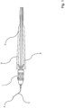
- Fig. 1 shows a schematic representation of a side view of an ophthalmological handheld device according to the invention.
- the handheld device has a base body 1, which is arranged on a handle 2.
- the handle comprises two grip elements 8.
- a guide tube 3 extends from the base body 1, the distal end 4 of which is sharp or pointed so that it can be inserted into an eye, for example through the conjunctiva into the front part of the eye.
- the guide tube 3 can thus be used as a cannula.
- the guide tube 3 is designed to be unrolled. However, it is conceivable that the guide tube 3 is designed to be straight.
- Fig. 2 to 5 show - enlarged - the distal end 4 of the hand-held device according to the invention.
- a gripping device 5 is arranged displaceably in the guide tube 3.
- the gripping arms 6 are opened so that an object 7, for example the haptics of an intraocular lens, can be grasped by the gripping arms 6.
- the gripping arms 6 are pulled back into the guide tube 3, the gripping arms 6 are pressed against one another so that the object 7 can be grasped and, if necessary, pulled into the guide tube 3.
- the handle 2 serves as an actuating means for moving the gripping device 5 within the guide tube 3.
- the handle can have two gripping elements 8, which are pre-tensioned, for example, by a spring. If the gripping elements 8 are pressed against one another, the gripping device 5 can be arranged at least substantially completely within the guide tube 3 (cf. Fig. 2 ). In this state, the distal end 4 can be inserted into the eye without the gripping device 5 injuring the eye or penetrating through eye tissue. is damaged. After the distal end 4 has been inserted into the eye, the surgeon can release the gripping elements 8 so that the gripping arms 6 are pushed out of the distal end 4 in order to grasp an object 7 (cf. Fig. 3 and 4 ).
- the gripping elements 8 can be pressed together so that the gripping arms 6 are displaced into the guide tube 4 together with the object 7 (cf. Fig. 5 ). In this state, the distal end 4 can be pulled out of the eye together with the object 7.
- the object 7, for example the haptics of an intraocular lens, is thus pulled through the scleral tunnel. It is pointed out that it is also possible for the gripping device 5 to be arranged inside the guide tube 4 when the handle 2 is not actuated and to be pushed out of the guide tube 4 by pressing the gripping elements 8 together.
- the outer edges 9 of the distal end 4 are designed as sharp cutting edges.
- the base body 1 can be removed from the handle 2 or is fixed or formed as one piece with the base body 1.
Landscapes
- Health & Medical Sciences (AREA)
- Life Sciences & Earth Sciences (AREA)
- General Health & Medical Sciences (AREA)
- Ophthalmology & Optometry (AREA)
- Surgery (AREA)
- Veterinary Medicine (AREA)
- Engineering & Computer Science (AREA)
- Biomedical Technology (AREA)
- Heart & Thoracic Surgery (AREA)
- Public Health (AREA)
- Animal Behavior & Ethology (AREA)
- Transplantation (AREA)
- Vascular Medicine (AREA)
- Oral & Maxillofacial Surgery (AREA)
- Nuclear Medicine, Radiotherapy & Molecular Imaging (AREA)
- Cardiology (AREA)
- Medical Informatics (AREA)
- Molecular Biology (AREA)
- Prostheses (AREA)
Description
- Die Erfindung betrifft ein ophthalmologisches Handgerät mit einem Grundkörper und einem mit dem Grundkörper verbundenen Führungsrohr, wobei ein distales Ende des Führungsrohrs scharf und/oder spitz ausgebildet ist, sodass dieses in ein Auge einstechbar ist.
- Ophthalmologische Handgeräte der in Rede stehenden Art werden bei unterschiedlichsten augenchirurgischen Eingriffen verwendet. Beispielsweise handelt es sich dabei um Kanülen, die in das Auge eingestochen werden, um in dem Augeninneren zu manipulieren.
- Bei einem solchen augenchirurgischen Eingriff kann es sich um die Implantation einer Intraokularlinse handeln. Dabei ist es mitunter notwendig, die Haptik der Intraokularlinse jeweils durch einen sogenannten Skleratunnel zu führen und damit die Intraokularlinse zu fixieren. Hierbei wird zunächst eine Kanüle in das Auge eingestochen, um den Skleratunnel zu bilden. Mit einem zweiten Instrument wird das Ende der Haptik in die Kanüle eingeschoben, sodass die Haptik mit der Kanüle durch den Skleratunnel aus dem Auge gezogen werden kann. An dieser Stelle kann sodann die Haptik festgelegt werden.
- Bei den bekannten Vorrichtungen ist es somit nachteilig, dass stets neben der Kanüle mindestens ein weiteres Instrument in das Auge eingeführt werden muss, um ein Objekt in dem Auge - beispielsweise die Haptik einer Intraokularlinse - in das Kanülenende einzubringen. Somit sind mehrere Öffnungen an dem Auge anzubringen, was ein erhöhtes Infektionsrisiko bedeutet und des Weiteren den Heilungsprozess verlängert. Weiterhin ist die Handhabung mehrerer Instrumente für den Operateur aufwändig, sodass hohe Anforderungen an das Geschick des Operators gestellt werden und der Eingriff relativ lange dauert.
-
US 2003/0088253 offenbart ein Ophthalmologisches Handgerät zur Extraktion von Intraokularlinsen. Das Handgerät weist ein Führungsrohr auf, wobei ein distales Ende des Führungsrohrs scharf ausgebildet ist, wobei eine Greifeinrichtung verschiebbar in dem Führungsrohr angeordnet ist. -
EP1285631 offenbart ein Ophthalmologisches Handgerät für die Netzhautchirurgie. Das Handgerät weist ein Führungsrohr auf, wobei eine Greifeinrichtung verschiebbar in dem Führungsrohr angeordnet ist. - Der vorliegenden Erfindung liegt daher die Aufgabe zugrunde, ein ophthalmologisches Handgerät der eingangs genannten Art derart auszugestalten und weiterzubilden, dass mit konstruktiv einfachen Mitteln die Handhabung verbessert wird.
- Erfindungsgemäß wird die voranstehende Aufgabe durch die Merkmale des Anspruches 1 gelöst. Danach ist das in Rede stehende ophthalmologische Handgerät dadurch gekennzeichnet, dass eine Greifeinrichtung verschiebbar in dem Führungsrohr angeordnet ist und dass die Greifeinrichtung aus dem Führungsrohr ausbringbar ist, um ein Objekt zu ergreifen.
- In erfindungsgemäßer Weise ist erkannt worden, dass durch die Kombination eines Führungsrohrs mit einem distalen Ende, welches scharf und/oder spitz ausgebildet ist und somit als Kanüle dienen kann, und einer Greifeinrichtung, mit welcher ein Objekt in dem Auge ergriffen werden kann, die zu Grunde liegende Aufgabe in überraschend einfacher Weise lösbar ist. Im Konkreten handelt es sich bei dem erfindungsgemäßen ophthalmologischen Handgerät um eine Kombination aus einer in das Auge einstechbaren Kanüle und einer Greifeinrichtung. Somit kann der Operateur zunächst das distale Ende des Führungsrohrs in das Auge einstechen und sodann über die in dem Führungsrohr angeordnete Greifeinrichtung die notwendige Manipulation innerhalb des Auges vornehmen. Somit ist lediglich eine einzige Inzision an dem Auge notwendig und kann der Operateur einhändig ein Objekt ergreifen. Im Konkreten könnte die Greifeinrichtung über ein Betätigungsmittel innerhalb des Führungsrohres verschoben bzw. bewegt werden. Auch ist es denkbar, dass ein von der Greifeinrichtung ergriffenes Objekt - bspw. eine Haptik - zumindest teilweise in das Führungsrohr hineingezogen werden kann.
- In vorteilhafter Weise ist die die Greifeinrichtung vollständig in das Führungsrohr einbringbar bzw. einziehbar. Somit kann das distale Ende des Führungsrohrs in idealer Weise zum Einstechen verwendet werden, ohne dass die Greifeinrichtung hierbei stört. Des Weiteren wird vermieden, dass die Greifeinrichtung beim Einstechen in das Auge beschädigt wird.
- In weiter vorteilhafter Weise kann der Grundkörper mit einem Handgriff verbunden sein. Dabei ist es des Weiteren denkbar, dass der Körper lösbar mit dem Handgriff verbunden ist. Somit könnte der Grundkörper als Einweginstrument ausgebildet sein und der Handgriff sterilisierbar sein. Alternativ könnten der Grundkörper und der Handgriff unlösbar miteinander verbunden bzw. einteilig ausgebildet sein.
- Gemäß einer weiteren vorteilhaften Ausgestaltung könnte der Handgriff als Betätigungsmittel dienen, um die Greifeinrichtung aus dem Führungsrohr auszubringen und/oder in das Führungsrohr einzubringen bzw. einzuziehen. Somit kann der Operateur bspw. durch ein Zusammendrücken des Handgriffs die Greifeinrichtung aus dem Führungsrohr ausbringen bzw. in dieses einziehen.
- Im Konkreten ist es denkbar, dass die Greifeinrichtung bei nicht betätigtem Handgriff aus dem Führungsrohr hinausragt und durch die Betätigung des Handgriffs in das Führungsrohr einbringbar ist bzw. eingezogen wird. Folglich könnte der Operateur zunächst mit betätigtem Handgriff das Führungsrohr in das Auge einstechen, wobei die Greifeinrichtung sich innerhalb des Führungsrohrs befindet. Sobald das Führungsrohr in das Auge eingestochen ist, kann der Chirurg den Handgriff freigeben, sodass die Greifeinrichtung aus dem Führungsrohr hinausgeschoben wird, um ein Objekt innerhalb des Auges zu ergreifen. Das Objekt könnte sodann durch eine Betätigung des Betätigungsmittels zumindest geringfügig in das Führungsrohr eingezogen werden. Auch ist es möglich, dass die Greifeinrichtung bei nicht aktiviertem Betätigungsmittel bzw. Handgriff zumindest im Wesentlichen in dem Führungsrohr angeordnet ist und durch Betätigung des Betätigungsmittels bzw. des Handgriffs aus dem Führungsrohr ausgebracht wird.
- In weiter vorteilhafter Weise könnte die Greifeinrichtung zwei miteinander zusammenwirkende Greifarme aufweisen. Die Greifarme könnten pinzettenartig ausgebildet sein bzw. Klemmbacken aufweisen. Dabei ist für die zugrundeliegende Offenbarung der Begriff "greifen" im weitesten Sinne zu verstehen. Beispielsweise könnte zumindest einer der Greifarme eine Schneide aufweisen, sodass die Greifeinrichtung auch zum Schneiden dienen könnte.
- Des Weiteren ist es denkbar, dass das Führungsrohr abgewinkelt ausgebildet ist. Eine solche Konstruktion kann für Eingriffe in Regionen des Auges vorteilhaft sein, die mit einem nicht abgewinkelten Führungsrohr nur schwer zu erreichen wären. Alternativ ist es denkbar, dass das Führungsrohr gerade ausgebildet ist. Eine solche Konstruktion zeichnet sich durch ihre einfache Herstellung aus.
- In besonders vorteilhafter Weise kann das Führungsrohr einen Durchmesser von kleiner oder gleich 30 Gauge aufweisen, vorzugsweise einen Durchmesser von kleiner oder gleich 27 Gauge. Eine entsprechende Dimensionierung erlaubt es, dass das Führungsrohr durch einen relativ kleinen Einstichkanal in das Auge einzubringen ist und ist des Weiteren ausreichend groß, um die Greifeinrichtung darin anzuordnen. Im Konkreten ist es denkbar, dass die Greifeinrichtung zum Eingreifen der Haptik einer Intraokularlinse dient. An dieser Stelle wird darauf hingewiesen, dass eine Intraokularlinse üblicherweise eine zentrale optische Linse aufweist, an der sich peripher eine Haptik anschließt, die die optische Linse im Auge fixiert. Die erfindungsgemäße Vorrichtung eignet sich in idealer Weise zur Fixierung der Haptik einer Intraokularlinse in einem Skleratunnel. Der Skleratunnel kann durch das Einstechen des Führungsrohrs in das Auge erzeugt werden, wobei die in dem Auge befindliche Haptik durch die Greifeinrichtung in die Öffnung an dem distalen Ende des Führungsrohrs eingezogen werden kann.
- Es gibt nun verschiedene Möglichkeiten, die Lehre der vorliegenden Erfindung in vorteilhafter Weise auszugestalten und weiterzubilden. Dazu ist einerseits auf die dem Anspruch 1 nachgeordneten Ansprüche und andererseits auf die nachfolgende Erläuterung bevorzugter Ausführungsbeispiele der Erfindung anhand der Zeichnung zu verweisen. In Verbindung mit der Erläuterung der bevorzugten Ausführungsbeispiele der Erfindung anhand der Zeichnung werden auch im Allgemeinen bevorzugte Ausgestaltungen und Weiterbildungen der Lehre erläutert. In der Zeichnung zeigen
- Fig. 1
- in einer schematischen Darstellung, eine Seitenansicht eines erfindungsgemäßen ophthalmologischen Handgeräts,
- Fig. 2
- in einer schematischen, perspektivischen Darstellung das distale Ende eines erfindungsgemäßen ophthalmologischen Handgeräts,
- Fig. 3
- in einer schematischen Darstellung eine Seitenansicht des distalen Endes eines erfindungsgemäßen ophthalmologischen Handgeräts gemäß
Fig. 2 , - Fig. 4
- in einer weiteren schematischen Darstellung eine Seitenansicht des distalen Endes eines erfindungsgemäßen ophthalmologischen Handgeräts gemäß
Fig. 2 , und - Fig. 5
- in einer weiteren schematischen, perspektivischen Darstellung das distale Ende eines erfindungsgemäßen ophthalmologischen Handgeräts gemäß
Fig. 2 . -
Fig. 1 zeigt in einer schematischen Darstellung, eine Seitenansicht eines erfindungsgemäßen ophthalmologischen Handgeräts. Das Handgerät weist einen Grundkörper 1 auf, der an einem Handgriff 2 angeordnet ist. Der Handgriff umfasst zwei Griffelemente 8. Von dem Grundkörper 1 erstreckt sich ein Führungsrohr 3, dessen distales Ende 4 scharf bzw. spitz ausgebildet ist, sodass dieses in ein Auge, beispielsweise durch die Bindehaut in den vorderen Augenabschnitt hinein, einstechbar ist. Das Führungsrohr 3 ist somit als Kanüle verwendbar. In dem hier dargestellten Ausführungsbeispiel ist das Führungsrohr 3 abgewickelt ausgebildet. Es ist jedoch denkbar, dass das Führungsrohr 3 gerade ausgestaltet ist. - Die
Fig. 2 bis 5 zeigen - vergrößert - das distale Ende 4 des erfindungsgemäßen Handgeräts. Dabei ist deutlich zu erkennen, dass in dem Führungsrohr 3 eine Greifeinrichtung 5 verschiebbar angeordnet ist. Bei einem Herausschieben der Greifeinrichtung 5 aus den Führungsrohr 3 werden die Greifarme 6 geöffnet, sodass ein Objekt 7, beispielsweise die Haptik einer Intraokularlinse, von den Greifarmen 6 ergriffen werden kann. Beim Zurückziehen der Greifarme 6 in das Führungsrohr 3 hinein werden die Greifarme 6 gegeneinandergedrückt, sodass das Objekt 7 ergriffen und ggf. in das Führungsrohr 3 eingezogen werden kann. - In dem hier dargestellten Ausführungsbeispiel dient der Handgriff 2 als Betätigungsmittel zum Verschieben der Greifeinrichtung 5 innerhalb des Führungsrohrs 3. Hierzu kann der Handgriff zwei Griffelemente 8 aufweisen, die beispielsweise über eine Feder vorgespannt sind. Sofern die Griffelemente 8 gegeneinandergedrückt sind, kann die Greifeinrichtung 5 zumindest im Wesentlichen vollständig innerhalb des Führungsrohr 3 angeordnet sein (vgl.
Fig. 2 ). In diesem Zustand kann das distale Ende 4 in das Auge eingestochen werden, ohne dass die Greifeinrichtung 5 das Auge verletzt oder durch Augengewebe beschädigt wird. Nachdem das distale Ende 4 in das Auge eingeführt ist, kann der Chirurg die Griffelemente 8 freigeben, so dass die Greifarme 6 aus dem distalen Ende 4 herausgeschoben werden, um ein Objekt 7 zu erfassen (vgl.Fig. 3 und4 ). - Wenn sich das Objekt 7 zwischen den Greifarmen 6 befindet, können die Griffelemente 8 zusammengedrückt werden, so dass die Greifarme 6 zusammen mit dem Objekt 7 in das Führungsrohr 4 verlagert werden (vgl.
Fig. 5 ). In diesem Zustand kann das distale Ende 4 zusammen mit dem Objekt 7 aus dem Auge gezogen werden. Somit wird das Objekt 7, beispielsweise die Haptik einer Intraokularlinse, durch den Skleratunnel gezogen. Es wird darauf hingewiesen, dass es auch möglich ist, dass die Greifeinrichtung 5 bei nicht betätigtem Handgriff 2 innerhalb des Führungsrohrs 4 angeordnet ist und durch ein Zusammendrücken der Griffelemente 8 aus dem Führungsrohr 4 herausgeschoben wird. - Um das distale Ende 4 möglichst einfach in das Auge einstechen zu können, ist es denkbar, dass die äußeren Kanten 9 des distalen Endes 4 als scharfe Schneidkanten realisiert sind. Des Weiteren ist es denkbar, dass der Grundkörper 1 von dem Handgriff 2 abgenommen werden kann oder fest bzw. einteilig mit dem Grundkörper 1 ausgebildet ist.
- Hinsichtlich weiterer vorteilhafter Ausgestaltungen der erfindungsgemäßen Vorrichtung wird zur Vermeidung von Wiederholungen auf den allgemeinen Teil der Beschreibung sowie auf die beigefügten Ansprüche verwiesen.
- Schließlich sei ausdrücklich darauf hingewiesen, dass die voranstehend beschriebenen Ausführungsbeispiele der erfindungsgemäßen Vorrichtung lediglich zur Erörterung der beanspruchten Lehre dienen, diese jedoch nicht auf die Ausführungsbeispiele einschränken.
-
- 1
- Grundkörper
- 2
- Handgriff
- 3
- Führungsrohr
- 4
- distales Ende (Führungsrohr)
- 5
- Greifeinrichtung
- 6
- Greifarme
- 7
- Objekt
- 8
- Griffelement
- 9
- äußere Kante (distales Ende)
Claims (10)
- Ophthalmologisches Handgerät mit einem Grundkörper (1) und einem mit dem Grundkörper (1) verbundenen Führungsrohr (4), wobei eine Greifeinrichtung (5) verschiebbar in dem Führungsrohr (4) angeordnet ist und dass die Greifeinrichtung (5) aus dem Führungsrohr (4) ausbringbar ist, um ein Objekt (7) zu ergreifen,
dadurch gekennzeichnet,
dass ein distales Ende (4) des Führungsrohrs (4) scharf und/oder spitz ausgebildet ist, so dass dieses in ein Auge einstechbar ist. - Ophthalmologisches Handgerät nach Anspruch 1, dadurch gekennzeichnet, dass die Greifeinrichtung (5) vollständig in das Führungsrohr (4) einbringbar ist.
- Ophthalmologisches Handgerät nach Anspruch 1 oder 2, dadurch gekennzeichnet, dass der Grundkörper (1), vorzugsweise lösbar, mit einem Handgriff (2) verbunden ist.
- Ophthalmologisches Handgerät nach Anspruch 3, dadurch gekennzeichnet, dass der Handgriff (2) als Betätigungsmittel dient, um die Greifeinrichtung (5) aus dem Führungsrohr (4) auszubringen und/oder in das Führungsrohr (4) einzubringen.
- Ophthalmologisches Handgerät nach Anspruch 4, dadurch gekennzeichnet, dass die Greifeinrichtung (5) bei nicht betätigtem Handgriff (2) aus dem Führungsrohr (4) hinausragt und durch Betätigung des Handgriffs (2) in das Führungsrohr (4) einbringbar ist.
- Ophthalmologisches Handgerät nach einem der Ansprüche 1 bis 5, dadurch gekennzeichnet, dass die Greifeinrichtung (5) zwei miteinander zusammenwirkende Greifarme (6) aufweist.
- Ophthalmologisches Handgerät nach einem der Ansprüche 1 bis 6, dadurch gekennzeichnet, dass das Führungsrohr (4) abgewinkelt ausgebildet ist.
- Ophthalmologisches Handgerät nach einem der Ansprüche 1 bis 6, dadurch gekennzeichnet, dass das Führungsrohr (4) gerade ausgebildet ist.
- Ophthalmologisches Handgerät nach einem der Ansprüche 1 bis 8, dadurch gekennzeichnet, dass das Führungsrohr (4) einen Durchmesser von kleiner oder gleich 30 Gauge, vorzugsweise von kleiner oder gleich 27 Gauge aufweist.
- Ophthalmologisches Handgerät nach einem der Ansprüche 1 bis 9, dadurch gekennzeichnet, dass die Greifeinrichtung (5) zum Ergreifen der Haptik einer Intraokularlinse dient.
Applications Claiming Priority (1)
| Application Number | Priority Date | Filing Date | Title |
|---|---|---|---|
| DE102019201833.5A DE102019201833A1 (de) | 2019-02-13 | 2019-02-13 | Ophthalmologisches Handgerät |
Publications (2)
| Publication Number | Publication Date |
|---|---|
| EP3695809A1 EP3695809A1 (de) | 2020-08-19 |
| EP3695809B1 true EP3695809B1 (de) | 2024-10-23 |
Family
ID=69156251
Family Applications (1)
| Application Number | Title | Priority Date | Filing Date |
|---|---|---|---|
| EP20150832.2A Active EP3695809B1 (de) | 2019-02-13 | 2020-01-09 | Ophthalmologisches handgerät |
Country Status (4)
| Country | Link |
|---|---|
| EP (1) | EP3695809B1 (de) |
| DE (1) | DE102019201833A1 (de) |
| ES (1) | ES3004612T3 (de) |
| PL (1) | PL3695809T3 (de) |
Citations (1)
| Publication number | Priority date | Publication date | Assignee | Title |
|---|---|---|---|---|
| EP1285631A2 (de) * | 2001-08-23 | 2003-02-26 | Alcon Grieshaber AG | Mikrochirurgisches Instrument |
Family Cites Families (3)
| Publication number | Priority date | Publication date | Assignee | Title |
|---|---|---|---|---|
| US20030088253A1 (en) * | 2001-11-07 | 2003-05-08 | Seil Randolph L | Dual action ophthalmic implant extractor |
| US9492187B2 (en) * | 2006-03-13 | 2016-11-15 | Teleflex Medical Incorporated | Minimally invasive surgical assembly and methods |
| KR102013539B1 (ko) * | 2013-04-16 | 2019-08-22 | 텔리플렉스 메디컬 인코포레이티드 | 최소 절개 수술 조립체 및 방법 |
-
2019
- 2019-02-13 DE DE102019201833.5A patent/DE102019201833A1/de active Pending
-
2020
- 2020-01-09 PL PL20150832.2T patent/PL3695809T3/pl unknown
- 2020-01-09 EP EP20150832.2A patent/EP3695809B1/de active Active
- 2020-01-09 ES ES20150832T patent/ES3004612T3/es active Active
Patent Citations (1)
| Publication number | Priority date | Publication date | Assignee | Title |
|---|---|---|---|---|
| EP1285631A2 (de) * | 2001-08-23 | 2003-02-26 | Alcon Grieshaber AG | Mikrochirurgisches Instrument |
Also Published As
| Publication number | Publication date |
|---|---|
| EP3695809A1 (de) | 2020-08-19 |
| ES3004612T3 (en) | 2025-03-12 |
| DE102019201833A1 (de) | 2020-08-13 |
| PL3695809T3 (pl) | 2025-04-28 |
Similar Documents
| Publication | Publication Date | Title |
|---|---|---|
| DE19704580C2 (de) | Chirurgischer Fadenschneider | |
| DE19518388C2 (de) | Medizinisches Instrument mit einem abwinkelbaren distalen Endstück | |
| DE19827468B4 (de) | Ligaturvorrichtung für ein Endoskop | |
| EP2957233B1 (de) | Gelenk-biopsienadel zur entnahme von gewebeproben | |
| DE602006000798T2 (de) | Vorrichtung zum Schützen eines spitzen Endes einer Kanüle und Verfahren zur Benutzung derselbigen Vorrichtung | |
| DE102010028167A1 (de) | Invasives Instrument zur Bearbeitung von Gefäßen und ein Verfahren | |
| EP2241273A1 (de) | Zerlegbares chirurgisches Instrument | |
| EP3701890B1 (de) | Ein ophthalmologisches handgerät sowie ein set umfassend ein ophthalmologisches handgerät | |
| DE102018112346A1 (de) | Medizinisches Instrument | |
| DE102012202434A1 (de) | Medizinisches Instrument | |
| WO1998003121A1 (de) | Trokarhülse für die endoskopie | |
| EP3695809A1 (de) | Ophthalmologisches handgerät | |
| EP1900325A1 (de) | Vorrichtung zur fetalen Skalpblutentnahme | |
| CH712350A2 (de) | Trokarset, insbesondere für die Augenhinterabschnittschirurgie, und Schutzkappe dafür. | |
| DE19707851A1 (de) | Nadelinstrument | |
| DE102018009476B3 (de) | Excisionsskalpell | |
| DE10100332A1 (de) | Medizinische Schneidvorrichtung | |
| DE10032007A1 (de) | Schneidinstrument für die Entnahme von Gewebeproben, insbesondere von Glaskörperchen | |
| DE102005002465B4 (de) | Ophthalmologisches Instrument | |
| EP1661598B1 (de) | Piercingnadel | |
| DE112006003824T5 (de) | Lanzette | |
| WO2018083190A1 (de) | Punktionsvorrichtung, vorrichtung zur beleuchtung von gewebe und medizinisches set | |
| DE4216874C1 (de) | ||
| DE29508254U1 (de) | Operationshülse zur Karpaltunnel-Spaltung | |
| AT514923B1 (de) | Instrument zum chirurgischen Nähen bei der minimal-invasiven Chirurgie und Nadelhalterkupplung für ein derartiges Instrument |
Legal Events
| Date | Code | Title | Description |
|---|---|---|---|
| PUAI | Public reference made under article 153(3) epc to a published international application that has entered the european phase |
Free format text: ORIGINAL CODE: 0009012 |
|
| STAA | Information on the status of an ep patent application or granted ep patent |
Free format text: STATUS: THE APPLICATION HAS BEEN PUBLISHED |
|
| AK | Designated contracting states |
Kind code of ref document: A1 Designated state(s): AL AT BE BG CH CY CZ DE DK EE ES FI FR GB GR HR HU IE IS IT LI LT LU LV MC MK MT NL NO PL PT RO RS SE SI SK SM TR |
|
| AX | Request for extension of the european patent |
Extension state: BA ME |
|
| STAA | Information on the status of an ep patent application or granted ep patent |
Free format text: STATUS: REQUEST FOR EXAMINATION WAS MADE |
|
| 17P | Request for examination filed |
Effective date: 20210205 |
|
| RBV | Designated contracting states (corrected) |
Designated state(s): AL AT BE BG CH CY CZ DE DK EE ES FI FR GB GR HR HU IE IS IT LI LT LU LV MC MK MT NL NO PL PT RO RS SE SI SK SM TR |
|
| GRAP | Despatch of communication of intention to grant a patent |
Free format text: ORIGINAL CODE: EPIDOSNIGR1 |
|
| STAA | Information on the status of an ep patent application or granted ep patent |
Free format text: STATUS: GRANT OF PATENT IS INTENDED |
|
| RIC1 | Information provided on ipc code assigned before grant |
Ipc: A61B 17/30 20060101ALI20240626BHEP Ipc: A61F 2/16 20060101AFI20240626BHEP |
|
| INTG | Intention to grant announced |
Effective date: 20240704 |
|
| GRAS | Grant fee paid |
Free format text: ORIGINAL CODE: EPIDOSNIGR3 |
|
| GRAA | (expected) grant |
Free format text: ORIGINAL CODE: 0009210 |
|
| STAA | Information on the status of an ep patent application or granted ep patent |
Free format text: STATUS: THE PATENT HAS BEEN GRANTED |
|
| P01 | Opt-out of the competence of the unified patent court (upc) registered |
Free format text: CASE NUMBER: APP_47285/2024 Effective date: 20240815 |
|
| AK | Designated contracting states |
Kind code of ref document: B1 Designated state(s): AL AT BE BG CH CY CZ DE DK EE ES FI FR GB GR HR HU IE IS IT LI LT LU LV MC MK MT NL NO PL PT RO RS SE SI SK SM TR |
|
| REG | Reference to a national code |
Ref country code: GB Ref legal event code: FG4D Free format text: NOT ENGLISH |
|
| REG | Reference to a national code |
Ref country code: CH Ref legal event code: EP |
|
| REG | Reference to a national code |
Ref country code: DE Ref legal event code: R096 Ref document number: 502020009535 Country of ref document: DE |
|
| REG | Reference to a national code |
Ref country code: IE Ref legal event code: FG4D Free format text: LANGUAGE OF EP DOCUMENT: GERMAN |
|
| REG | Reference to a national code |
Ref country code: NL Ref legal event code: FP |
|
| REG | Reference to a national code |
Ref country code: LT Ref legal event code: MG9D |
|
| REG | Reference to a national code |
Ref country code: ES Ref legal event code: FG2A Ref document number: 3004612 Country of ref document: ES Kind code of ref document: T3 Effective date: 20250312 |
|
| PG25 | Lapsed in a contracting state [announced via postgrant information from national office to epo] |
Ref country code: PT Free format text: LAPSE BECAUSE OF FAILURE TO SUBMIT A TRANSLATION OF THE DESCRIPTION OR TO PAY THE FEE WITHIN THE PRESCRIBED TIME-LIMIT Effective date: 20250224 Ref country code: HR Free format text: LAPSE BECAUSE OF FAILURE TO SUBMIT A TRANSLATION OF THE DESCRIPTION OR TO PAY THE FEE WITHIN THE PRESCRIBED TIME-LIMIT Effective date: 20241023 Ref country code: IS Free format text: LAPSE BECAUSE OF FAILURE TO SUBMIT A TRANSLATION OF THE DESCRIPTION OR TO PAY THE FEE WITHIN THE PRESCRIBED TIME-LIMIT Effective date: 20250223 |
|
| PG25 | Lapsed in a contracting state [announced via postgrant information from national office to epo] |
Ref country code: FI Free format text: LAPSE BECAUSE OF FAILURE TO SUBMIT A TRANSLATION OF THE DESCRIPTION OR TO PAY THE FEE WITHIN THE PRESCRIBED TIME-LIMIT Effective date: 20241023 |
|
| PG25 | Lapsed in a contracting state [announced via postgrant information from national office to epo] |
Ref country code: BG Free format text: LAPSE BECAUSE OF FAILURE TO SUBMIT A TRANSLATION OF THE DESCRIPTION OR TO PAY THE FEE WITHIN THE PRESCRIBED TIME-LIMIT Effective date: 20241023 |
|
| PG25 | Lapsed in a contracting state [announced via postgrant information from national office to epo] |
Ref country code: NO Free format text: LAPSE BECAUSE OF FAILURE TO SUBMIT A TRANSLATION OF THE DESCRIPTION OR TO PAY THE FEE WITHIN THE PRESCRIBED TIME-LIMIT Effective date: 20250123 |
|
| PG25 | Lapsed in a contracting state [announced via postgrant information from national office to epo] |
Ref country code: LV Free format text: LAPSE BECAUSE OF FAILURE TO SUBMIT A TRANSLATION OF THE DESCRIPTION OR TO PAY THE FEE WITHIN THE PRESCRIBED TIME-LIMIT Effective date: 20241023 Ref country code: GR Free format text: LAPSE BECAUSE OF FAILURE TO SUBMIT A TRANSLATION OF THE DESCRIPTION OR TO PAY THE FEE WITHIN THE PRESCRIBED TIME-LIMIT Effective date: 20250124 |
|
| PG25 | Lapsed in a contracting state [announced via postgrant information from national office to epo] |
Ref country code: RS Free format text: LAPSE BECAUSE OF FAILURE TO SUBMIT A TRANSLATION OF THE DESCRIPTION OR TO PAY THE FEE WITHIN THE PRESCRIBED TIME-LIMIT Effective date: 20250123 |
|
| PG25 | Lapsed in a contracting state [announced via postgrant information from national office to epo] |
Ref country code: SM Free format text: LAPSE BECAUSE OF FAILURE TO SUBMIT A TRANSLATION OF THE DESCRIPTION OR TO PAY THE FEE WITHIN THE PRESCRIBED TIME-LIMIT Effective date: 20241023 |
|
| PGFP | Annual fee paid to national office [announced via postgrant information from national office to epo] |
Ref country code: DE Payment date: 20250430 Year of fee payment: 6 |
|
| PG25 | Lapsed in a contracting state [announced via postgrant information from national office to epo] |
Ref country code: DK Free format text: LAPSE BECAUSE OF FAILURE TO SUBMIT A TRANSLATION OF THE DESCRIPTION OR TO PAY THE FEE WITHIN THE PRESCRIBED TIME-LIMIT Effective date: 20241023 |
|
| PG25 | Lapsed in a contracting state [announced via postgrant information from national office to epo] |
Ref country code: EE Free format text: LAPSE BECAUSE OF FAILURE TO SUBMIT A TRANSLATION OF THE DESCRIPTION OR TO PAY THE FEE WITHIN THE PRESCRIBED TIME-LIMIT Effective date: 20241023 |
|
| PG25 | Lapsed in a contracting state [announced via postgrant information from national office to epo] |
Ref country code: RO Free format text: LAPSE BECAUSE OF FAILURE TO SUBMIT A TRANSLATION OF THE DESCRIPTION OR TO PAY THE FEE WITHIN THE PRESCRIBED TIME-LIMIT Effective date: 20241023 |
|
| REG | Reference to a national code |
Ref country code: DE Ref legal event code: R097 Ref document number: 502020009535 Country of ref document: DE |
|
| PG25 | Lapsed in a contracting state [announced via postgrant information from national office to epo] |
Ref country code: SK Free format text: LAPSE BECAUSE OF FAILURE TO SUBMIT A TRANSLATION OF THE DESCRIPTION OR TO PAY THE FEE WITHIN THE PRESCRIBED TIME-LIMIT Effective date: 20241023 |
|
| PG25 | Lapsed in a contracting state [announced via postgrant information from national office to epo] |
Ref country code: CZ Free format text: LAPSE BECAUSE OF FAILURE TO SUBMIT A TRANSLATION OF THE DESCRIPTION OR TO PAY THE FEE WITHIN THE PRESCRIBED TIME-LIMIT Effective date: 20241023 |
|
| PLBE | No opposition filed within time limit |
Free format text: ORIGINAL CODE: 0009261 |
|
| STAA | Information on the status of an ep patent application or granted ep patent |
Free format text: STATUS: NO OPPOSITION FILED WITHIN TIME LIMIT |
|
| PG25 | Lapsed in a contracting state [announced via postgrant information from national office to epo] |
Ref country code: SE Free format text: LAPSE BECAUSE OF FAILURE TO SUBMIT A TRANSLATION OF THE DESCRIPTION OR TO PAY THE FEE WITHIN THE PRESCRIBED TIME-LIMIT Effective date: 20241023 |
|
| PG25 | Lapsed in a contracting state [announced via postgrant information from national office to epo] |
Ref country code: LU Free format text: LAPSE BECAUSE OF NON-PAYMENT OF DUE FEES Effective date: 20250109 Ref country code: MC Free format text: LAPSE BECAUSE OF FAILURE TO SUBMIT A TRANSLATION OF THE DESCRIPTION OR TO PAY THE FEE WITHIN THE PRESCRIBED TIME-LIMIT Effective date: 20241023 |
|
| 26N | No opposition filed |
Effective date: 20250724 |
|
| PG25 | Lapsed in a contracting state [announced via postgrant information from national office to epo] |
Ref country code: BE Free format text: LAPSE BECAUSE OF NON-PAYMENT OF DUE FEES Effective date: 20250131 |
|
| REG | Reference to a national code |
Ref country code: BE Ref legal event code: MM Effective date: 20250131 |
|
| PG25 | Lapsed in a contracting state [announced via postgrant information from national office to epo] |
Ref country code: IE Free format text: LAPSE BECAUSE OF NON-PAYMENT OF DUE FEES Effective date: 20250109 |
|
| REG | Reference to a national code |
Ref country code: CH Ref legal event code: U11 Free format text: ST27 STATUS EVENT CODE: U-0-0-U10-U11 (AS PROVIDED BY THE NATIONAL OFFICE) Effective date: 20260201 |
|
| PGFP | Annual fee paid to national office [announced via postgrant information from national office to epo] |
Ref country code: NL Payment date: 20260121 Year of fee payment: 7 |
|
| PGFP | Annual fee paid to national office [announced via postgrant information from national office to epo] |
Ref country code: GB Payment date: 20260122 Year of fee payment: 7 |
|
| PGFP | Annual fee paid to national office [announced via postgrant information from national office to epo] |
Ref country code: ES Payment date: 20260217 Year of fee payment: 7 |
|
| PGFP | Annual fee paid to national office [announced via postgrant information from national office to epo] |
Ref country code: AT Payment date: 20260119 Year of fee payment: 7 |
|
| PGFP | Annual fee paid to national office [announced via postgrant information from national office to epo] |
Ref country code: IT Payment date: 20260130 Year of fee payment: 7 |
|
| PGFP | Annual fee paid to national office [announced via postgrant information from national office to epo] |
Ref country code: FR Payment date: 20260123 Year of fee payment: 7 |
|
| PGFP | Annual fee paid to national office [announced via postgrant information from national office to epo] |
Ref country code: CH Payment date: 20260201 Year of fee payment: 7 |
|
| PGFP | Annual fee paid to national office [announced via postgrant information from national office to epo] |
Ref country code: PL Payment date: 20251229 Year of fee payment: 7 |