EP3696007B1 - Anordnung zum erden eines gleichspannungszwischenkreises - Google Patents
Anordnung zum erden eines gleichspannungszwischenkreises Download PDFInfo
- Publication number
- EP3696007B1 EP3696007B1 EP20150676.3A EP20150676A EP3696007B1 EP 3696007 B1 EP3696007 B1 EP 3696007B1 EP 20150676 A EP20150676 A EP 20150676A EP 3696007 B1 EP3696007 B1 EP 3696007B1
- Authority
- EP
- European Patent Office
- Prior art keywords
- handle
- contact members
- intermediate link
- earthing
- casing
- Prior art date
- Legal status (The legal status is an assumption and is not a legal conclusion. Google has not performed a legal analysis and makes no representation as to the accuracy of the status listed.)
- Active
Links
Images



Classifications
-
- B—PERFORMING OPERATIONS; TRANSPORTING
- B60—VEHICLES IN GENERAL
- B60L—PROPULSION OF ELECTRICALLY-PROPELLED VEHICLES; SUPPLYING ELECTRIC POWER FOR AUXILIARY EQUIPMENT OF ELECTRICALLY-PROPELLED VEHICLES; ELECTRODYNAMIC BRAKE SYSTEMS FOR VEHICLES IN GENERAL; MAGNETIC SUSPENSION OR LEVITATION FOR VEHICLES; MONITORING OPERATING VARIABLES OF ELECTRICALLY-PROPELLED VEHICLES; ELECTRIC SAFETY DEVICES FOR ELECTRICALLY-PROPELLED VEHICLES
- B60L3/00—Electric devices on electrically-propelled vehicles for safety purposes; Monitoring operating variables, e.g. speed, deceleration or energy consumption
- B60L3/0023—Detecting, eliminating, remedying or compensating for drive train abnormalities, e.g. failures within the drive train
- B60L3/0069—Detecting, eliminating, remedying or compensating for drive train abnormalities, e.g. failures within the drive train relating to the isolation, e.g. ground fault or leak current
-
- H—ELECTRICITY
- H02—GENERATION; CONVERSION OR DISTRIBUTION OF ELECTRIC POWER
- H02M—APPARATUS FOR CONVERSION BETWEEN AC AND AC, BETWEEN AC AND DC, OR BETWEEN DC AND DC, AND FOR USE WITH MAINS OR SIMILAR POWER SUPPLY SYSTEMS; CONVERSION OF DC OR AC INPUT POWER INTO SURGE OUTPUT POWER; CONTROL OR REGULATION THEREOF
- H02M7/00—Conversion of AC power input into DC power output; Conversion of DC power input into AC power output
- H02M7/003—Constructional details, e.g. physical layout, assembly, wiring or busbar connections
-
- H—ELECTRICITY
- H01—ELECTRIC ELEMENTS
- H01R—ELECTRICALLY-CONDUCTIVE CONNECTIONS; STRUCTURAL ASSOCIATIONS OF A PLURALITY OF MUTUALLY-INSULATED ELECTRICAL CONNECTING ELEMENTS; COUPLING DEVICES; CURRENT COLLECTORS
- H01R13/00—Details of coupling devices of the kinds covered by groups H01R12/70 or H01R24/00 - H01R33/00
- H01R13/02—Contact members
-
- B—PERFORMING OPERATIONS; TRANSPORTING
- B60—VEHICLES IN GENERAL
- B60L—PROPULSION OF ELECTRICALLY-PROPELLED VEHICLES; SUPPLYING ELECTRIC POWER FOR AUXILIARY EQUIPMENT OF ELECTRICALLY-PROPELLED VEHICLES; ELECTRODYNAMIC BRAKE SYSTEMS FOR VEHICLES IN GENERAL; MAGNETIC SUSPENSION OR LEVITATION FOR VEHICLES; MONITORING OPERATING VARIABLES OF ELECTRICALLY-PROPELLED VEHICLES; ELECTRIC SAFETY DEVICES FOR ELECTRICALLY-PROPELLED VEHICLES
- B60L3/00—Electric devices on electrically-propelled vehicles for safety purposes; Monitoring operating variables, e.g. speed, deceleration or energy consumption
- B60L3/04—Cutting off the power supply under fault conditions
-
- B—PERFORMING OPERATIONS; TRANSPORTING
- B60—VEHICLES IN GENERAL
- B60R—VEHICLES, VEHICLE FITTINGS, OR VEHICLE PARTS, NOT OTHERWISE PROVIDED FOR
- B60R16/00—Electric or fluid circuits specially adapted for vehicles and not otherwise provided for; Arrangement of elements of electric or fluid circuits specially adapted for vehicles and not otherwise provided for
- B60R16/02—Electric or fluid circuits specially adapted for vehicles and not otherwise provided for; Arrangement of elements of electric or fluid circuits specially adapted for vehicles and not otherwise provided for electric constitutive elements
- B60R16/03—Electric or fluid circuits specially adapted for vehicles and not otherwise provided for; Arrangement of elements of electric or fluid circuits specially adapted for vehicles and not otherwise provided for electric constitutive elements for supply of electrical power to vehicle subsystems or for
-
- H—ELECTRICITY
- H01—ELECTRIC ELEMENTS
- H01R—ELECTRICALLY-CONDUCTIVE CONNECTIONS; STRUCTURAL ASSOCIATIONS OF A PLURALITY OF MUTUALLY-INSULATED ELECTRICAL CONNECTING ELEMENTS; COUPLING DEVICES; CURRENT COLLECTORS
- H01R13/00—Details of coupling devices of the kinds covered by groups H01R12/70 or H01R24/00 - H01R33/00
- H01R13/46—Bases; Cases
- H01R13/502—Bases; Cases composed of different pieces
-
- H—ELECTRICITY
- H01—ELECTRIC ELEMENTS
- H01R—ELECTRICALLY-CONDUCTIVE CONNECTIONS; STRUCTURAL ASSOCIATIONS OF A PLURALITY OF MUTUALLY-INSULATED ELECTRICAL CONNECTING ELEMENTS; COUPLING DEVICES; CURRENT COLLECTORS
- H01R13/00—Details of coupling devices of the kinds covered by groups H01R12/70 or H01R24/00 - H01R33/00
- H01R13/62—Means for facilitating engagement or disengagement of coupling parts or for holding them in engagement
- H01R13/629—Additional means for facilitating engagement or disengagement of coupling parts, e.g. aligning or guiding means, levers, gas pressure electrical locking indicators, manufacturing tolerances
-
- H—ELECTRICITY
- H01—ELECTRIC ELEMENTS
- H01R—ELECTRICALLY-CONDUCTIVE CONNECTIONS; STRUCTURAL ASSOCIATIONS OF A PLURALITY OF MUTUALLY-INSULATED ELECTRICAL CONNECTING ELEMENTS; COUPLING DEVICES; CURRENT COLLECTORS
- H01R4/00—Electrically-conductive connections between two or more conductive members in direct contact, i.e. touching one another; Means for effecting or maintaining such contact; Electrically-conductive connections having two or more spaced connecting locations for conductors and using contact members penetrating insulation
- H01R4/58—Electrically-conductive connections between two or more conductive members in direct contact, i.e. touching one another; Means for effecting or maintaining such contact; Electrically-conductive connections having two or more spaced connecting locations for conductors and using contact members penetrating insulation characterised by the form or material of the contacting members
- H01R4/64—Connections between or with conductive parts having primarily a non-electric function, e.g. frame, casing, rail
-
- H—ELECTRICITY
- H01—ELECTRIC ELEMENTS
- H01R—ELECTRICALLY-CONDUCTIVE CONNECTIONS; STRUCTURAL ASSOCIATIONS OF A PLURALITY OF MUTUALLY-INSULATED ELECTRICAL CONNECTING ELEMENTS; COUPLING DEVICES; CURRENT COLLECTORS
- H01R43/00—Apparatus or processes specially adapted for manufacturing, assembling, maintaining, or repairing of line connectors or current collectors or for joining electric conductors
- H01R43/26—Apparatus or processes specially adapted for manufacturing, assembling, maintaining, or repairing of line connectors or current collectors or for joining electric conductors for engaging or disengaging the two parts of a coupling device
-
- H—ELECTRICITY
- H02—GENERATION; CONVERSION OR DISTRIBUTION OF ELECTRIC POWER
- H02B—BOARDS, SUBSTATIONS OR SWITCHING ARRANGEMENTS FOR THE SUPPLY OR DISTRIBUTION OF ELECTRIC POWER
- H02B11/00—Switchgear having carriage withdrawable for isolation
- H02B11/28—Earthing arrangements
-
- H—ELECTRICITY
- H05—ELECTRIC TECHNIQUES NOT OTHERWISE PROVIDED FOR
- H05K—PRINTED CIRCUITS; CASINGS OR CONSTRUCTIONAL DETAILS OF ELECTRIC APPARATUS; MANUFACTURE OF ASSEMBLAGES OF ELECTRICAL COMPONENTS
- H05K5/00—Casings, cabinets or drawers for electric apparatus
- H05K5/02—Details
- H05K5/0217—Mechanical details of casings
- H05K5/023—Handles; Grips
-
- H—ELECTRICITY
- H05—ELECTRIC TECHNIQUES NOT OTHERWISE PROVIDED FOR
- H05K—PRINTED CIRCUITS; CASINGS OR CONSTRUCTIONAL DETAILS OF ELECTRIC APPARATUS; MANUFACTURE OF ASSEMBLAGES OF ELECTRICAL COMPONENTS
- H05K5/00—Casings, cabinets or drawers for electric apparatus
- H05K5/02—Details
- H05K5/03—Covers
-
- B—PERFORMING OPERATIONS; TRANSPORTING
- B60—VEHICLES IN GENERAL
- B60L—PROPULSION OF ELECTRICALLY-PROPELLED VEHICLES; SUPPLYING ELECTRIC POWER FOR AUXILIARY EQUIPMENT OF ELECTRICALLY-PROPELLED VEHICLES; ELECTRODYNAMIC BRAKE SYSTEMS FOR VEHICLES IN GENERAL; MAGNETIC SUSPENSION OR LEVITATION FOR VEHICLES; MONITORING OPERATING VARIABLES OF ELECTRICALLY-PROPELLED VEHICLES; ELECTRIC SAFETY DEVICES FOR ELECTRICALLY-PROPELLED VEHICLES
- B60L2200/00—Type of vehicles
- B60L2200/26—Rail vehicles
-
- H—ELECTRICITY
- H01—ELECTRIC ELEMENTS
- H01H—ELECTRIC SWITCHES; RELAYS; SELECTORS; EMERGENCY PROTECTIVE DEVICES
- H01H31/00—Air-break switches for high tension without arc-extinguishing or arc-preventing means
- H01H31/003—Earthing switches
-
- H—ELECTRICITY
- H01—ELECTRIC ELEMENTS
- H01R—ELECTRICALLY-CONDUCTIVE CONNECTIONS; STRUCTURAL ASSOCIATIONS OF A PLURALITY OF MUTUALLY-INSULATED ELECTRICAL CONNECTING ELEMENTS; COUPLING DEVICES; CURRENT COLLECTORS
- H01R2201/00—Connectors or connections adapted for particular applications
- H01R2201/26—Connectors or connections adapted for particular applications for vehicles
Definitions
- the present invention relates to an arrangement for earthing a DC intermediate link connected to a converter on board a track-bound vehicle.
- the present invention is particularly directed to railway vehicles it does also cover other types of vehicles being track-bound, such as buses and trucks.
- separation contactors are usually first controlled to obtain a zero voltage at the converter, but it is then for safety reason also important to earth the DC intermediate link connected to the converter so that the voltage may not accidentally return during the maintenance work.
- EP2927044 A1 discloses an earthing arrangement for a DC link of a converter on board a track-bound vehicle according to the state of the art.
- EP2302748 A1 discloses a method for earthing two current inlet/outlet systems in a medium or high voltage switchgear according to the state of the art.
- the object of the present invention is to provide an arrangement of the type defined in the introduction being improved in at least some aspect with respect to such arrangements already known.
- the arrangement is configured to be permanently arranged on board a track-bound vehicle, which means that it has not to be carried along and brought to a place of use thereof, but it is ensured that it is always on board the track-bound vehicle ready to be used.
- the arrangement has two conducting members configured to have one end permanently connected to a pole each of a DC intermediate link and the other end connected to a first contact member each configured to be movably arranged with respect to a second contact member permanently connected to a chassis part of the vehicle connected to earth.
- the first contact members are movable with respect to the second contact members between an open position not earthing said DC intermediate link and a contacting closed position earthing the DC intermediate link.
- a handle is connected to the first or second contact members while being electrically insulated with respect thereto to be manually operated for moving the contact members connected thereto between a position of not earthing and a position of earthing the DC intermediate link.
- the arrangement is permanently on the place where it is to be used and has also permanently said first contact members connected to the poles of a DC intermediate link to be earthed making it possible to easily and reliably obtain earthing of the DC intermediate link of the converter in question by simply manually operating the handle connected to the first or second contact members, which may be carried out without exposing the maintenance operator for any type of danger.
- a separate arrangement of this type is preferably arranged for all converters, for example line converters and motor converters, on board the track-bound vehicle, which allows the maintenance operator to be certain that the DC intermediate link of a specific converter is earthed independently from the rest of the system.
- the arrangement comprises a carrier onto which both contact members connected to the handle are arranged and which is guidedly displaceable along a member fixed with respect to said chassis part.
- the contact members connected to the handle may by this through operating the handle comfortably be brought to the state of contacting the other contact members and earthing the DC intermediate link.
- the member fixed with respect to the chassis part has not to be secured to a chassis part, but it has only to be immovable with respect to the chassis part.
- said carrier has at least portions made of insulating material connecting the carrier and by that the contact members arranged thereon to said handle.
- said first contact members are plate-like metal members, and according to a further development of this embodiment the second contact members are configured to bear under pretension against large surfaces of the first contact members in a closed position, which ensures that the earthing state is reliably maintained once it has been obtained.
- each said second contact member forms a jaw configured to receive a said first contact member while bearing under pretension from opposite directions thereagainst in said closed position.
- the arrangement is configured to be arranged inside a converter casing with said handle accessible to be operated under the condition that a front cover of the casing is removed for exposing an opening into the casing.
- the handle may by this not be unintentionally moved to an earthing position when this is not asked for, since the front cover of the converter casing has to be removed for operating the handle and this is only done when a maintenance operator is really going to carry out maintenance work.
- the handle is configured to be arranged to be pulled out of the casing for obtaining said contacting closed position and pushed into the casing for obtaining said open position. This ensures that a DC intermediate link may not be left earthed by the arrangement when the front cover has been brought into place, since applying the front cover to the casing requires a pushing of the handle into the casing and by that resulting in an open position of the contact members of the arrangement.
- the front cover is in a position of closing the opening of the casing configured to hold the handle in a position corresponding to a position of said contact members not earthing the DC intermediate link. It is by this ensured that the earthing arrangement is always in the neutral not earthing position as long as the front cover is closing the casing opening.
- the arrangement comprises means for locking the handle with the first and second contact members in the closed position. This ensures that a maintenance operator or any other person may not unintentionally move the handle and causing a non-earthing position of the arrangement when work is carried out for the converter in question.
- said means is configured to lock the handle with the first and second contact members in the closed position in a position of the handle preventing said front cover to closing the converter casing opening. This ensures that the front cover may not be put in place as long as the DC intermediate link is earthed.
- said conducting members are flexible, which simplifies the creation of an arrangement with the properties aimed at through the invention.
- the conducting members are then preferably electrical cables.
- the invention also relates to a method for earthing a DC intermediate link connected to a converter on board a track-bound vehicle, which is characterized by utilising an arrangement according to the invention and by carrying out the steps of opening a front cover of a converter casing containing said converter and DC intermediate link and pulling the handle out through a casing opening previously covered by the front cover to a position in which the first contact members and the second contact members are in mutual contact connecting the DC intermediate link to earth.
- This way of obtaining said earthing will avoid that unintentional closing of the front cover is taking place.
- the method comprises the further step of locking the handle in the pulled out position for preventing the handle to be unintentionally pushed into the casing to a position corresponding to not earthing the DC intermediate link.
- the invention also relates to a track-bound vehicle having for at least one, preferably all, converters on board thereof an arrangement according to the invention for earthing a DC intermediate link connected to the converter.
- Fig 1 illustrates schematically how electric power may be fed to a track-bound vehicle 1 from an AC-supply line 2 and used in the vehicle.
- the vehicle is configured to move along the AC-supply line 2 which accordingly acts as an AC-source and which may for example carry a single phase alternating voltage of 15 kV and 16 2/3 Hz (Sweden, Germany etc.) or 25 kV and 50 Hz (Denmark, China, India etc.).
- the vehicle has a transformer 3 for transforming the voltage from the supply line 2 to a suitable level.
- the transformer has here two secondary windings 4, 5 connected to a line converter 6, 7 each for delivering a direct voltage of for example 0.8 - 3 kV on the output thereof.
- this direct voltage is then present between poles 8, 9 and 10, 11 of DC intermediate links 12 and 13, respectively.
- These DC intermediate links are connected to an input of a motor converter 14, 15 each controlled for delivering a three-phase alternating voltage on the output thereof to motors 16, 17 for the propulsion of the vehicle.
- Electric power may in a corresponding way be delivered from a corresponding DC intermediate link to an auxiliary converter for providing electric power to sockets arranged in the track-bound vehicle, such as for connection of computers, and to lighting, heating and other appliances.
- Fig 2 shows such an arrangement according to an embodiment of the invention.
- the arrangement has a frame with a bracket 20 for securing the arrangement to the frame 21 (see Fig 4 ) of a converter casing 22 containing the converter and electronic equipment associated with the control thereof and also the DC intermediate link connected thereto.
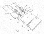
- the arrangement has two conducting members 23, 24 in the form of electrical cables configured to have one end 25, 26 connected to a pole each of a DC intermediate link and the other end 27, 28 connected to a first contact member 29, 30 each in the form of a metal plate.
- the first contact members 29, 30 are arranged on a carrier 31 being guidedly displaceable along a member 32 fixed with respect to a chassis part of the vehicle through the bracket 20.
- the carrier 31 has at least portions 33 made of insulating material connecting the carrier and by that the first contact members 29, 30 to a handle 34.
- the arrangement further comprises second contact members 35, 36 permanently connected to a chassis part of the vehicle connected to earth through an earth connecting member 37.
- the first contact members 29, 30 are movable with respect to the second contact members 35, 36 between an open position not earthing said DC intermediate link shown in Fig 2 and a contacting closed position earthing the DC intermediate link shown in Fig 3 .
- the second contact members 35, 36 are designed as jaws configured to receive the first contact member while bearing under pretension from opposite directions thereagainst in the closed position shown in Fig 3 .
- a separation contactor is controlled to obtain a zero voltage between the poles of the DC intermediate link, which however in some cases will in fact be a voltage differing from zero, such as 24 V, still remaining.
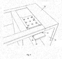
- the front cover is then removed from the converter casing 22 to expose the handle 34 of the arrangement as shown in Fig 4 . It is shown how the front cover has pushed the handle into the casing to ensure that the arrangement is in a not earthing state when the front cover is put in place.
- the handle 34 is then gripped by the maintenance operator and pulled out of the casing opening 38 to the position shown in Fig 5 in which the first contact members 29, 30 has been brought into contact with the second contact members 35, 36 and by that the poles of the DC intermediate link in contact with a chassis part of the vehicle for earthing the DC intermediate link.
- the handle may be connected to the second contact members then movable for obtaining the movement of the contact members with respect to each other between said open position not earthing the DC intermediate link and said contacting closed position earthing the DC intermediate link.
- the second contact members may then be permanently connected to a said chassis part connected to earth by conducting members, such as flexible electrical cables.
- Fig 1 shows the invention applied to earthing a DC intermediate link connected to a converter on board a track-bound vehicle fed by an AC-supply line, but the earthing arrangement according to the invention may also be used for DC applications, such as having DC supplies of 750 VDC or 1 500 VDC.
- Auxiliary contacts inside the earthing device not shown in the figures are configured to detect the position of the earthing device, and information provided thereby may be used to supervise the position of the earthing device and to interlock power contactors upstreams to be energized and connect voltage to the DC intermediate link.
Landscapes
- Engineering & Computer Science (AREA)
- Power Engineering (AREA)
- Mechanical Engineering (AREA)
- Microelectronics & Electronic Packaging (AREA)
- Life Sciences & Earth Sciences (AREA)
- Sustainable Development (AREA)
- Sustainable Energy (AREA)
- Transportation (AREA)
- Manufacturing & Machinery (AREA)
- Electric Propulsion And Braking For Vehicles (AREA)
- Handcart (AREA)
Claims (15)
- Eine Anordnung zur Erdung eines mit einem Umrichter (6, 7, 14, 15) verbundenen Gleichstromzwischenkreises (12, 13) an Bord eines schienengebundenen Fahrzeugs (1),
dadurch gekennzeichnet, dass sie dazu ausgebildet ist, dauerhaft an Bord eines schienengebundenen Fahrzeugs angeordnet zu sein, und sie umfasst:- zwei leitende Elemente (23, 24), die dazu ausgebildet sind, mit einem Ende (25, 26) dauerhaft mit je einem Pol (8-11) des Gleichstromzwischenkreises verbunden zu sein und mit dem anderen Ende (27, 28) verbunden zu sein mit- einem ersten Kontaktelement (29, 30), das jeweils dazu ausgebildet ist, beweglich angeordnet zu sein in Bezug auf- zweite Kontaktelemente (35, 36), die dauerhaft mit einem geerdeten Fahrwerksteil des Fahrzeugs verbunden sind,
wobei die ersten Kontaktelemente (29, 30) in Bezug auf die zweiten Kontaktelemente (35, 36) beweglich sind zwischen einer offenen Position, in welcher der Gleichstromzwischenkreis (12, 13) nicht geerdet ist, und einer kontaktierenden, geschlossenen Position, in welcher der Gleichstromzwischenkreis geerdet ist, und- einen Griff (34), der mit den ersten oder zweiten Kontaktelementen verbunden ist, während er gegenüber diesen elektrisch isoliert ist, um manuell betätigt zu werden, um die damit verbundenen Kontaktelemente zwischen einer Position, in welcher der Gleichstromzwischenkreis nicht geerdet wird, und einer Position zu bewegen, in welcher der Gleichstromzwischenkreis geerdet wird, wobei ein Element (32) in Bezug auf das Fahrwerksteil fixiert ist, und- einen Träger (31), auf dem beide mit dem Griff (34) verbundenen Kontaktelemente (29, 30) angeordnet sind und der geführt entlang des Elements (32) verschiebbar ist. - Eine Anordnung nach Anspruch 1, dadurch gekennzeichnet, dass der Träger (31) wenigstens Abschnitte (33) aus Isoliermaterial aufweist, die den Träger und dadurch die darauf angeordneten Kontaktelemente (29, 30) mit dem Griff verbinden.
- Eine Anordnung nach einem der vorhergehenden Ansprüche, dadurch gekennzeichnet, dass die ersten Kontaktelemente (29, 30) plattenartige Metallelemente sind.
- Eine Anordnung nach Anspruch 3, dadurch gekennzeichnet, dass die zweiten Kontaktelemente (35, 36) dazu ausgebildet sind, dass sie in der geschlossenen Position unter Vorspannung gegen große Flächen der ersten Kontaktelemente (29, 30) drücken.
- Eine Anordnung nach Anspruch 4, dadurch gekennzeichnet, dass jedes zweite Kontaktelement (35, 36) eine Backe bildet, die dazu ausgebildet ist, dass sie ein erstes Kontaktelement (29, 30) aufnimmt, während sie in der geschlossenen Position unter Vorspannung aus entgegengesetzten Richtungen gegen dieses drückt.
- Eine Anordnung nach einem der vorhergehenden Ansprüche, dadurch gekennzeichnet, dass sie dazu ausgebildet ist innerhalb eines Umrichtergehäuses (22) angeordnet zu sein, wobei der Griff (34) zugänglich ist, um unter der Bedingung bedient zu werden, dass eine Frontabdeckung des Gehäuses entfernt wird, um eine Öffnung (38) in das Gehäuse freizugeben.
- Eine Anordnung nach Anspruch 6, dadurch gekennzeichnet, dass der Griff (34) dazu ausgebildet ist angeordnet zu sein, um aus dem Gehäuse (22) herausgezogen zu werden, um die kontaktierende, geschlossene Position zu erhalten, und um in das Gehäuse hineingedrückt zu werden, um die offene Position zu erhalten.
- Eine Anordnung nach Anspruch 6 oder 7, dadurch gekennzeichnet, dass die Frontabdeckung dazu ausgebildet ist, in einer Position, in der die Öffnung (38) des Gehäuses verschlossen ist, den Griff (34) in einer Position zu halten, die einer Position entspricht, in welcher die Kontaktelemente den Gleichstromzwischenkreis (12, 13) nicht erden.
- Eine Anordnung nach einem der vorhergehenden Ansprüche, dadurch gekennzeichnet, dass sie Mittel (39, 40) zum Verriegeln des Griffs mit den ersten (29, 30) und zweiten (35, 36) Kontaktelementen in der geschlossenen Position umfasst.
- Eine Anordnung nach Anspruch 6 oder 7 oder 8 und nach Anspruch 9, dadurch gekennzeichnet, dass die Mittel (39, 40) dazu ausgebildet sind, den Griff (34) mit den ersten (29, 30) und zweiten (35, 36) Kontaktelementen in der geschlossenen Position in einer Position des Griffs zu verriegeln, die verhindert, dass die Frontabdeckung die Umrichtergehäuseöffnung (38) schließt.
- Eine Anordnung nach einem der vorhergehenden Ansprüche, dadurch gekennzeichnet, dass die leitenden Elemente (23, 24) flexibel sind.
- Eine Anordnung nach Anspruch 11, dadurch gekennzeichnet, dass die leitenden Elemente (23, 24) elektrische Kabel sind.
- Ein Verfahren zur Erdung eines mit einem Umrichter (6, 7, 14, 15) verbundenen Gleichstromzwischenkreises (12, 13) an Bord eines schienengebundenen Fahrzeugs (1), gekennzeichnet durch Verwendung einer Anordnung (18, 19) nach einem der vorhergehenden Ansprüche und durch Ausführen der Schritte:- Öffnen einer Frontabdeckung eines Umrichtergehäuses (22), das den Umrichter und den Gleichstromzwischenkreis enthält, und- Herausziehen des Griffs (34) durch eine zuvor von der Frontabdeckung abgedeckte Gehäuseöffnung (38) in eine Position, in der die ersten Kontaktelemente (29, 30) und die zweiten Kontaktelemente (35, 36) in gegenseitigem Kontakt stehen, wobei sie den Gleichstromzwischenkreis (12, 13) erden.
- Ein Verfahren nach Anspruch 13, dadurch gekennzeichnet, dass es den weiteren Schritt umfasst, den Griff (34) in der herausgezogenen Position zu verriegeln, um zu verhindern, dass der Griff unbeabsichtigt in das Gehäuse (22) in eine Position gedrückt wird, die einer Nichterdung des Gleichstromzwischenkreises (12, 13) entspricht.
- Ein schienengebundenes Fahrzeug, das für wenigstens einen, vorzugsweise für alle, Umrichter an Bord eine Anordnung (18, 19) nach einem der Ansprüche 1-12 zur Erdung eines mit einem Umrichter (6, 7, 14, 15) verbundenen Gleichstromzwischenkreises (12, 13) aufweist.
Applications Claiming Priority (1)
| Application Number | Priority Date | Filing Date | Title |
|---|---|---|---|
| SE1950200 | 2019-02-18 |
Publications (2)
| Publication Number | Publication Date |
|---|---|
| EP3696007A1 EP3696007A1 (de) | 2020-08-19 |
| EP3696007B1 true EP3696007B1 (de) | 2021-10-06 |
Family
ID=69156186
Family Applications (1)
| Application Number | Title | Priority Date | Filing Date |
|---|---|---|---|
| EP20150676.3A Active EP3696007B1 (de) | 2019-02-18 | 2020-01-08 | Anordnung zum erden eines gleichspannungszwischenkreises |
Country Status (4)
| Country | Link |
|---|---|
| US (1) | US11336196B2 (de) |
| EP (1) | EP3696007B1 (de) |
| CN (2) | CN111585077B (de) |
| RU (1) | RU2020107099A (de) |
Families Citing this family (2)
| Publication number | Priority date | Publication date | Assignee | Title |
|---|---|---|---|---|
| WO2019242843A1 (de) * | 2018-06-19 | 2019-12-26 | Siemens Aktiengesellschaft | Potentialausgleichsystem für einen modularen multilevel-stromrichter |
| EP3696007B1 (de) * | 2019-02-18 | 2021-10-06 | Bombardier Transportation GmbH | Anordnung zum erden eines gleichspannungszwischenkreises |
Citations (2)
| Publication number | Priority date | Publication date | Assignee | Title |
|---|---|---|---|---|
| EP2927044A1 (de) * | 2014-03-31 | 2015-10-07 | Siemens Aktiengesellschaft | Verfahren zum Betreiben paralleler Hilfsbetriebeumrichter in einem Schienenfahrzeug |
| EP3618142A1 (de) * | 2018-08-30 | 2020-03-04 | ABB Schweiz AG | Diensttrennungs- und erdungskonzept für ein batteriespeichersystems |
Family Cites Families (12)
| Publication number | Priority date | Publication date | Assignee | Title |
|---|---|---|---|---|
| DE19856772A1 (de) * | 1998-11-30 | 2000-05-31 | Siemens Ag | Schaltanlagen mit Leistungsschaltereinrichtungen |
| US6497182B2 (en) * | 2000-02-02 | 2002-12-24 | General Electric Company | Railroad locomotive traction motor isolation |
| JPWO2007138645A1 (ja) | 2006-05-25 | 2009-10-01 | 三菱電機株式会社 | 車両用補助電源装置 |
| WO2009088977A1 (en) | 2008-01-09 | 2009-07-16 | Petra Solar Inc. | Photovoltaic panel with hot plug connector |
| KR101320167B1 (ko) | 2009-06-12 | 2013-10-23 | 미쓰비시덴키 가부시키가이샤 | 차량용 전력 변환 장치 |
| EP2302748B1 (de) * | 2009-09-23 | 2012-05-16 | ABB Technology | Mittel- oder Hochspannungsschaltvorrichtung und Erdungsverfahren |
| EP2605395A1 (de) * | 2011-12-13 | 2013-06-19 | Bombardier Transportation GmbH | Wandler für schienengebundene Fahrzeuge |
| US9991795B2 (en) * | 2015-04-24 | 2018-06-05 | Epc Power Corporation | Power converter with controllable DC offset |
| WO2016191662A1 (en) * | 2015-05-27 | 2016-12-01 | Intelligent Technologies International, Inc. | Vehicle wire harness |
| ES2725717T3 (es) * | 2016-11-23 | 2019-09-26 | Bombardier Transp Gmbh | Multisistema eléctrico para un vehículo ferroviario |
| CN107139774B (zh) | 2017-04-18 | 2020-06-30 | 上海蔚来汽车有限公司 | 电动汽车及其主动放电模块、驱动装置、电驱动系统 |
| EP3696007B1 (de) * | 2019-02-18 | 2021-10-06 | Bombardier Transportation GmbH | Anordnung zum erden eines gleichspannungszwischenkreises |
-
2020
- 2020-01-08 EP EP20150676.3A patent/EP3696007B1/de active Active
- 2020-02-13 US US16/789,689 patent/US11336196B2/en active Active
- 2020-02-17 RU RU2020107099A patent/RU2020107099A/ru unknown
- 2020-02-17 CN CN202010095453.2A patent/CN111585077B/zh active Active
- 2020-02-17 CN CN202020176202.2U patent/CN211556210U/zh active Active
Patent Citations (2)
| Publication number | Priority date | Publication date | Assignee | Title |
|---|---|---|---|---|
| EP2927044A1 (de) * | 2014-03-31 | 2015-10-07 | Siemens Aktiengesellschaft | Verfahren zum Betreiben paralleler Hilfsbetriebeumrichter in einem Schienenfahrzeug |
| EP3618142A1 (de) * | 2018-08-30 | 2020-03-04 | ABB Schweiz AG | Diensttrennungs- und erdungskonzept für ein batteriespeichersystems |
Also Published As
| Publication number | Publication date |
|---|---|
| CN211556210U (zh) | 2020-09-22 |
| CN111585077A (zh) | 2020-08-25 |
| EP3696007A1 (de) | 2020-08-19 |
| RU2020107099A (ru) | 2021-08-17 |
| CN111585077B (zh) | 2025-06-10 |
| US11336196B2 (en) | 2022-05-17 |
| US20200266725A1 (en) | 2020-08-20 |
Similar Documents
| Publication | Publication Date | Title |
|---|---|---|
| CN104918820B (zh) | 用于电动车辆的充电设备 | |
| DE102012200442B4 (de) | Elektronikeinheit mit Stromabtastung | |
| EP2699446B1 (de) | Fahrzeugladevorrichtung | |
| EP3238978A1 (de) | Kombinierte multilevel-umrichter- und acdc leistungslade-einheit | |
| CN102300748B (zh) | 用于机动车辆的互连壳体 | |
| EP3696007B1 (de) | Anordnung zum erden eines gleichspannungszwischenkreises | |
| JP6200012B2 (ja) | バッテリ用の充電システムを含む車両 | |
| CN105264761A (zh) | 放电控制装置 | |
| DE102017203063B3 (de) | Antriebssteuergerät und Verfahren zum Laden einer Batterie | |
| EP0980793A3 (de) | Schaltungsanordnung und Verfahren zur Abschaltung einer elektrischen Energiequelle eines Fahrzeuges | |
| DE102021124894A1 (de) | Ladekabel für eine Ladestation, Ladestation, System mit einer Mehrzahl von Ladestationen und Verfahren zum Betreiben einer Ladestation | |
| CN111801242B (zh) | 机动车辆的交流充电装置及其运行方法和机动车辆 | |
| CN115003546A (zh) | 电动车辆充电装置和相应方法 | |
| CN111204241A (zh) | 用于将充电外围控制器集成到未电流隔离的充电装置中的方法和系统 | |
| WO2023046397A1 (de) | Ladestation und system mit einer mehrzahl von ladestationen | |
| DE102016213054B3 (de) | Fahrzeugbordnetz und Verfahren | |
| DE102021124937A1 (de) | Ladekabel für eine ladestation, ladestation, system mit einer mehrzahl von ladestationen und verfahren zum betreiben einer ladestation | |
| JP2016123178A (ja) | ケーブル接続装置 | |
| DE112020006975T5 (de) | Leistungsumwandlungsvorrichtung | |
| WO2023046399A1 (de) | Ladekabel für eine ladestation, ladestation, system mit einer mehrzahl von ladestationen und verfahren zum betreiben einer ladestation | |
| EP2088669A2 (de) | Vorrichtung und Verfahren zum Betrieb von Maschinen an einphasigem Wechselstrom oder dreiphasigem Drehstrom zur Verarbeitung von Mörtel | |
| EP3402691B1 (de) | Elektrosystem für ein fahrzeug, fahrzeug sowie verfahren zum durchführen eines ladevorgangs | |
| JP7253109B2 (ja) | 変換器盤、ユニット引き出し方法、および、無停電電源装置 | |
| JP3018603U (ja) | 多極絶縁テストスイッチ | |
| DE190664C (de) |
Legal Events
| Date | Code | Title | Description |
|---|---|---|---|
| PUAI | Public reference made under article 153(3) epc to a published international application that has entered the european phase |
Free format text: ORIGINAL CODE: 0009012 |
|
| STAA | Information on the status of an ep patent application or granted ep patent |
Free format text: STATUS: THE APPLICATION HAS BEEN PUBLISHED |
|
| AK | Designated contracting states |
Kind code of ref document: A1 Designated state(s): AL AT BE BG CH CY CZ DE DK EE ES FI FR GB GR HR HU IE IS IT LI LT LU LV MC MK MT NL NO PL PT RO RS SE SI SK SM TR |
|
| AX | Request for extension of the european patent |
Extension state: BA ME |
|
| STAA | Information on the status of an ep patent application or granted ep patent |
Free format text: STATUS: REQUEST FOR EXAMINATION WAS MADE |
|
| 17P | Request for examination filed |
Effective date: 20200827 |
|
| RBV | Designated contracting states (corrected) |
Designated state(s): AL AT BE BG CH CY CZ DE DK EE ES FI FR GB GR HR HU IE IS IT LI LT LU LV MC MK MT NL NO PL PT RO RS SE SI SK SM TR |
|
| STAA | Information on the status of an ep patent application or granted ep patent |
Free format text: STATUS: EXAMINATION IS IN PROGRESS |
|
| 17Q | First examination report despatched |
Effective date: 20201116 |
|
| GRAP | Despatch of communication of intention to grant a patent |
Free format text: ORIGINAL CODE: EPIDOSNIGR1 |
|
| STAA | Information on the status of an ep patent application or granted ep patent |
Free format text: STATUS: GRANT OF PATENT IS INTENDED |
|
| INTG | Intention to grant announced |
Effective date: 20210510 |
|
| GRAS | Grant fee paid |
Free format text: ORIGINAL CODE: EPIDOSNIGR3 |
|
| GRAA | (expected) grant |
Free format text: ORIGINAL CODE: 0009210 |
|
| STAA | Information on the status of an ep patent application or granted ep patent |
Free format text: STATUS: THE PATENT HAS BEEN GRANTED |
|
| AK | Designated contracting states |
Kind code of ref document: B1 Designated state(s): AL AT BE BG CH CY CZ DE DK EE ES FI FR GB GR HR HU IE IS IT LI LT LU LV MC MK MT NL NO PL PT RO RS SE SI SK SM TR |
|
| REG | Reference to a national code |
Ref country code: GB Ref legal event code: FG4D |
|
| REG | Reference to a national code |
Ref country code: CH Ref legal event code: EP Ref country code: AT Ref legal event code: REF Ref document number: 1435932 Country of ref document: AT Kind code of ref document: T Effective date: 20211015 |
|
| REG | Reference to a national code |
Ref country code: DE Ref legal event code: R096 Ref document number: 602020000645 Country of ref document: DE |
|
| REG | Reference to a national code |
Ref country code: IE Ref legal event code: FG4D |
|
| REG | Reference to a national code |
Ref country code: LT Ref legal event code: MG9D |
|
| REG | Reference to a national code |
Ref country code: NL Ref legal event code: MP Effective date: 20211006 |
|
| REG | Reference to a national code |
Ref country code: AT Ref legal event code: MK05 Ref document number: 1435932 Country of ref document: AT Kind code of ref document: T Effective date: 20211006 |
|
| PG25 | Lapsed in a contracting state [announced via postgrant information from national office to epo] |
Ref country code: RS Free format text: LAPSE BECAUSE OF FAILURE TO SUBMIT A TRANSLATION OF THE DESCRIPTION OR TO PAY THE FEE WITHIN THE PRESCRIBED TIME-LIMIT Effective date: 20211006 Ref country code: LT Free format text: LAPSE BECAUSE OF FAILURE TO SUBMIT A TRANSLATION OF THE DESCRIPTION OR TO PAY THE FEE WITHIN THE PRESCRIBED TIME-LIMIT Effective date: 20211006 Ref country code: FI Free format text: LAPSE BECAUSE OF FAILURE TO SUBMIT A TRANSLATION OF THE DESCRIPTION OR TO PAY THE FEE WITHIN THE PRESCRIBED TIME-LIMIT Effective date: 20211006 Ref country code: BG Free format text: LAPSE BECAUSE OF FAILURE TO SUBMIT A TRANSLATION OF THE DESCRIPTION OR TO PAY THE FEE WITHIN THE PRESCRIBED TIME-LIMIT Effective date: 20220106 Ref country code: AT Free format text: LAPSE BECAUSE OF FAILURE TO SUBMIT A TRANSLATION OF THE DESCRIPTION OR TO PAY THE FEE WITHIN THE PRESCRIBED TIME-LIMIT Effective date: 20211006 |
|
| PG25 | Lapsed in a contracting state [announced via postgrant information from national office to epo] |
Ref country code: IS Free format text: LAPSE BECAUSE OF FAILURE TO SUBMIT A TRANSLATION OF THE DESCRIPTION OR TO PAY THE FEE WITHIN THE PRESCRIBED TIME-LIMIT Effective date: 20220206 Ref country code: SE Free format text: LAPSE BECAUSE OF FAILURE TO SUBMIT A TRANSLATION OF THE DESCRIPTION OR TO PAY THE FEE WITHIN THE PRESCRIBED TIME-LIMIT Effective date: 20211006 Ref country code: PT Free format text: LAPSE BECAUSE OF FAILURE TO SUBMIT A TRANSLATION OF THE DESCRIPTION OR TO PAY THE FEE WITHIN THE PRESCRIBED TIME-LIMIT Effective date: 20220207 Ref country code: PL Free format text: LAPSE BECAUSE OF FAILURE TO SUBMIT A TRANSLATION OF THE DESCRIPTION OR TO PAY THE FEE WITHIN THE PRESCRIBED TIME-LIMIT Effective date: 20211006 Ref country code: NO Free format text: LAPSE BECAUSE OF FAILURE TO SUBMIT A TRANSLATION OF THE DESCRIPTION OR TO PAY THE FEE WITHIN THE PRESCRIBED TIME-LIMIT Effective date: 20220106 Ref country code: NL Free format text: LAPSE BECAUSE OF FAILURE TO SUBMIT A TRANSLATION OF THE DESCRIPTION OR TO PAY THE FEE WITHIN THE PRESCRIBED TIME-LIMIT Effective date: 20211006 Ref country code: LV Free format text: LAPSE BECAUSE OF FAILURE TO SUBMIT A TRANSLATION OF THE DESCRIPTION OR TO PAY THE FEE WITHIN THE PRESCRIBED TIME-LIMIT Effective date: 20211006 Ref country code: HR Free format text: LAPSE BECAUSE OF FAILURE TO SUBMIT A TRANSLATION OF THE DESCRIPTION OR TO PAY THE FEE WITHIN THE PRESCRIBED TIME-LIMIT Effective date: 20211006 Ref country code: GR Free format text: LAPSE BECAUSE OF FAILURE TO SUBMIT A TRANSLATION OF THE DESCRIPTION OR TO PAY THE FEE WITHIN THE PRESCRIBED TIME-LIMIT Effective date: 20220107 Ref country code: ES Free format text: LAPSE BECAUSE OF FAILURE TO SUBMIT A TRANSLATION OF THE DESCRIPTION OR TO PAY THE FEE WITHIN THE PRESCRIBED TIME-LIMIT Effective date: 20211006 |
|
| REG | Reference to a national code |
Ref country code: DE Ref legal event code: R097 Ref document number: 602020000645 Country of ref document: DE |
|
| PG25 | Lapsed in a contracting state [announced via postgrant information from national office to epo] |
Ref country code: SM Free format text: LAPSE BECAUSE OF FAILURE TO SUBMIT A TRANSLATION OF THE DESCRIPTION OR TO PAY THE FEE WITHIN THE PRESCRIBED TIME-LIMIT Effective date: 20211006 Ref country code: SK Free format text: LAPSE BECAUSE OF FAILURE TO SUBMIT A TRANSLATION OF THE DESCRIPTION OR TO PAY THE FEE WITHIN THE PRESCRIBED TIME-LIMIT Effective date: 20211006 Ref country code: RO Free format text: LAPSE BECAUSE OF FAILURE TO SUBMIT A TRANSLATION OF THE DESCRIPTION OR TO PAY THE FEE WITHIN THE PRESCRIBED TIME-LIMIT Effective date: 20211006 Ref country code: EE Free format text: LAPSE BECAUSE OF FAILURE TO SUBMIT A TRANSLATION OF THE DESCRIPTION OR TO PAY THE FEE WITHIN THE PRESCRIBED TIME-LIMIT Effective date: 20211006 Ref country code: DK Free format text: LAPSE BECAUSE OF FAILURE TO SUBMIT A TRANSLATION OF THE DESCRIPTION OR TO PAY THE FEE WITHIN THE PRESCRIBED TIME-LIMIT Effective date: 20211006 Ref country code: CZ Free format text: LAPSE BECAUSE OF FAILURE TO SUBMIT A TRANSLATION OF THE DESCRIPTION OR TO PAY THE FEE WITHIN THE PRESCRIBED TIME-LIMIT Effective date: 20211006 |
|
| PLBE | No opposition filed within time limit |
Free format text: ORIGINAL CODE: 0009261 |
|
| STAA | Information on the status of an ep patent application or granted ep patent |
Free format text: STATUS: NO OPPOSITION FILED WITHIN TIME LIMIT |
|
| PG25 | Lapsed in a contracting state [announced via postgrant information from national office to epo] |
Ref country code: MC Free format text: LAPSE BECAUSE OF FAILURE TO SUBMIT A TRANSLATION OF THE DESCRIPTION OR TO PAY THE FEE WITHIN THE PRESCRIBED TIME-LIMIT Effective date: 20211006 |
|
| 26N | No opposition filed |
Effective date: 20220707 |
|
| REG | Reference to a national code |
Ref country code: BE Ref legal event code: MM Effective date: 20220131 |
|
| PG25 | Lapsed in a contracting state [announced via postgrant information from national office to epo] |
Ref country code: LU Free format text: LAPSE BECAUSE OF NON-PAYMENT OF DUE FEES Effective date: 20220108 Ref country code: AL Free format text: LAPSE BECAUSE OF FAILURE TO SUBMIT A TRANSLATION OF THE DESCRIPTION OR TO PAY THE FEE WITHIN THE PRESCRIBED TIME-LIMIT Effective date: 20211006 |
|
| PG25 | Lapsed in a contracting state [announced via postgrant information from national office to epo] |
Ref country code: SI Free format text: LAPSE BECAUSE OF FAILURE TO SUBMIT A TRANSLATION OF THE DESCRIPTION OR TO PAY THE FEE WITHIN THE PRESCRIBED TIME-LIMIT Effective date: 20211006 Ref country code: BE Free format text: LAPSE BECAUSE OF NON-PAYMENT OF DUE FEES Effective date: 20220131 |
|
| PG25 | Lapsed in a contracting state [announced via postgrant information from national office to epo] |
Ref country code: IE Free format text: LAPSE BECAUSE OF NON-PAYMENT OF DUE FEES Effective date: 20220108 |
|
| PG25 | Lapsed in a contracting state [announced via postgrant information from national office to epo] |
Ref country code: IT Free format text: LAPSE BECAUSE OF FAILURE TO SUBMIT A TRANSLATION OF THE DESCRIPTION OR TO PAY THE FEE WITHIN THE PRESCRIBED TIME-LIMIT Effective date: 20211006 |
|
| P01 | Opt-out of the competence of the unified patent court (upc) registered |
Effective date: 20230822 |
|
| PG25 | Lapsed in a contracting state [announced via postgrant information from national office to epo] |
Ref country code: MK Free format text: LAPSE BECAUSE OF FAILURE TO SUBMIT A TRANSLATION OF THE DESCRIPTION OR TO PAY THE FEE WITHIN THE PRESCRIBED TIME-LIMIT Effective date: 20211006 Ref country code: CY Free format text: LAPSE BECAUSE OF FAILURE TO SUBMIT A TRANSLATION OF THE DESCRIPTION OR TO PAY THE FEE WITHIN THE PRESCRIBED TIME-LIMIT Effective date: 20211006 |
|
| PG25 | Lapsed in a contracting state [announced via postgrant information from national office to epo] |
Ref country code: HU Free format text: LAPSE BECAUSE OF FAILURE TO SUBMIT A TRANSLATION OF THE DESCRIPTION OR TO PAY THE FEE WITHIN THE PRESCRIBED TIME-LIMIT; INVALID AB INITIO Effective date: 20200108 |
|
| PG25 | Lapsed in a contracting state [announced via postgrant information from national office to epo] |
Ref country code: MT Free format text: LAPSE BECAUSE OF FAILURE TO SUBMIT A TRANSLATION OF THE DESCRIPTION OR TO PAY THE FEE WITHIN THE PRESCRIBED TIME-LIMIT Effective date: 20211006 |
|
| PG25 | Lapsed in a contracting state [announced via postgrant information from national office to epo] |
Ref country code: TR Free format text: LAPSE BECAUSE OF FAILURE TO SUBMIT A TRANSLATION OF THE DESCRIPTION OR TO PAY THE FEE WITHIN THE PRESCRIBED TIME-LIMIT Effective date: 20211006 |
|
| REG | Reference to a national code |
Ref country code: CH Ref legal event code: U11 Free format text: ST27 STATUS EVENT CODE: U-0-0-U10-U11 (AS PROVIDED BY THE NATIONAL OFFICE) Effective date: 20260201 |
|
| PGFP | Annual fee paid to national office [announced via postgrant information from national office to epo] |
Ref country code: GB Payment date: 20260123 Year of fee payment: 7 |
|
| PGFP | Annual fee paid to national office [announced via postgrant information from national office to epo] |
Ref country code: DE Payment date: 20260121 Year of fee payment: 7 |
|
| PGFP | Annual fee paid to national office [announced via postgrant information from national office to epo] |
Ref country code: FR Payment date: 20260123 Year of fee payment: 7 |
|
| PGFP | Annual fee paid to national office [announced via postgrant information from national office to epo] |
Ref country code: CH Payment date: 20260201 Year of fee payment: 7 |