EP3696009A1 - Procédé de symétrisation d'un courant triphasé - Google Patents
Procédé de symétrisation d'un courant triphasé Download PDFInfo
- Publication number
- EP3696009A1 EP3696009A1 EP19020066.7A EP19020066A EP3696009A1 EP 3696009 A1 EP3696009 A1 EP 3696009A1 EP 19020066 A EP19020066 A EP 19020066A EP 3696009 A1 EP3696009 A1 EP 3696009A1
- Authority
- EP
- European Patent Office
- Prior art keywords
- phase current
- phase
- current
- catenary
- train
- Prior art date
- Legal status (The legal status is an assumption and is not a legal conclusion. Google has not performed a legal analysis and makes no representation as to the accuracy of the status listed.)
- Granted
Links
Images


Classifications
-
- B—PERFORMING OPERATIONS; TRANSPORTING
- B60—VEHICLES IN GENERAL
- B60L—PROPULSION OF ELECTRICALLY-PROPELLED VEHICLES; SUPPLYING ELECTRIC POWER FOR AUXILIARY EQUIPMENT OF ELECTRICALLY-PROPELLED VEHICLES; ELECTRODYNAMIC BRAKE SYSTEMS FOR VEHICLES IN GENERAL; MAGNETIC SUSPENSION OR LEVITATION FOR VEHICLES; MONITORING OPERATING VARIABLES OF ELECTRICALLY-PROPELLED VEHICLES; ELECTRIC SAFETY DEVICES FOR ELECTRICALLY-PROPELLED VEHICLES
- B60L50/00—Electric propulsion with power supplied within the vehicle
- B60L50/50—Electric propulsion with power supplied within the vehicle using propulsion power supplied by batteries or fuel cells
-
- B—PERFORMING OPERATIONS; TRANSPORTING
- B60—VEHICLES IN GENERAL
- B60L—PROPULSION OF ELECTRICALLY-PROPELLED VEHICLES; SUPPLYING ELECTRIC POWER FOR AUXILIARY EQUIPMENT OF ELECTRICALLY-PROPELLED VEHICLES; ELECTRODYNAMIC BRAKE SYSTEMS FOR VEHICLES IN GENERAL; MAGNETIC SUSPENSION OR LEVITATION FOR VEHICLES; MONITORING OPERATING VARIABLES OF ELECTRICALLY-PROPELLED VEHICLES; ELECTRIC SAFETY DEVICES FOR ELECTRICALLY-PROPELLED VEHICLES
- B60L3/00—Electric devices on electrically-propelled vehicles for safety purposes; Monitoring operating variables, e.g. speed, deceleration or energy consumption
- B60L3/0023—Detecting, eliminating, remedying or compensating for drive train abnormalities, e.g. failures within the drive train
- B60L3/0046—Detecting, eliminating, remedying or compensating for drive train abnormalities, e.g. failures within the drive train relating to electric energy storage systems, e.g. batteries or capacitors
-
- B—PERFORMING OPERATIONS; TRANSPORTING
- B60—VEHICLES IN GENERAL
- B60L—PROPULSION OF ELECTRICALLY-PROPELLED VEHICLES; SUPPLYING ELECTRIC POWER FOR AUXILIARY EQUIPMENT OF ELECTRICALLY-PROPELLED VEHICLES; ELECTRODYNAMIC BRAKE SYSTEMS FOR VEHICLES IN GENERAL; MAGNETIC SUSPENSION OR LEVITATION FOR VEHICLES; MONITORING OPERATING VARIABLES OF ELECTRICALLY-PROPELLED VEHICLES; ELECTRIC SAFETY DEVICES FOR ELECTRICALLY-PROPELLED VEHICLES
- B60L58/00—Methods or circuit arrangements for monitoring or controlling batteries or fuel cells, specially adapted for electric vehicles
- B60L58/10—Methods or circuit arrangements for monitoring or controlling batteries or fuel cells, specially adapted for electric vehicles for monitoring or controlling batteries
- B60L58/18—Methods or circuit arrangements for monitoring or controlling batteries or fuel cells, specially adapted for electric vehicles for monitoring or controlling batteries of two or more battery modules
- B60L58/22—Balancing the charge of battery modules
-
- H—ELECTRICITY
- H02—GENERATION; CONVERSION OR DISTRIBUTION OF ELECTRIC POWER
- H02J—ELECTRIC POWER NETWORKS; CIRCUIT ARRANGEMENTS OR SYSTEMS FOR SUPPLYING OR DISTRIBUTING ELECTRIC POWER; SYSTEMS FOR STORING ELECTRIC ENERGY
- H02J3/00—Circuit arrangements for AC mains or AC distribution networks
- H02J3/26—Arrangements for eliminating or reducing asymmetry in polyphase networks
-
- B—PERFORMING OPERATIONS; TRANSPORTING
- B60—VEHICLES IN GENERAL
- B60L—PROPULSION OF ELECTRICALLY-PROPELLED VEHICLES; SUPPLYING ELECTRIC POWER FOR AUXILIARY EQUIPMENT OF ELECTRICALLY-PROPELLED VEHICLES; ELECTRODYNAMIC BRAKE SYSTEMS FOR VEHICLES IN GENERAL; MAGNETIC SUSPENSION OR LEVITATION FOR VEHICLES; MONITORING OPERATING VARIABLES OF ELECTRICALLY-PROPELLED VEHICLES; ELECTRIC SAFETY DEVICES FOR ELECTRICALLY-PROPELLED VEHICLES
- B60L2270/00—Problem solutions or means not otherwise provided for
- B60L2270/20—Inrush current reduction, i.e. avoiding high currents when connecting the battery
-
- G—PHYSICS
- G01—MEASURING; TESTING
- G01R—MEASURING ELECTRIC VARIABLES; MEASURING MAGNETIC VARIABLES
- G01R29/00—Arrangements for measuring or indicating electric quantities not covered by groups G01R19/00 - G01R27/00
- G01R29/16—Measuring asymmetry of polyphase networks
-
- Y—GENERAL TAGGING OF NEW TECHNOLOGICAL DEVELOPMENTS; GENERAL TAGGING OF CROSS-SECTIONAL TECHNOLOGIES SPANNING OVER SEVERAL SECTIONS OF THE IPC; TECHNICAL SUBJECTS COVERED BY FORMER USPC CROSS-REFERENCE ART COLLECTIONS [XRACs] AND DIGESTS
- Y02—TECHNOLOGIES OR APPLICATIONS FOR MITIGATION OR ADAPTATION AGAINST CLIMATE CHANGE
- Y02E—REDUCTION OF GREENHOUSE GAS [GHG] EMISSIONS, RELATED TO ENERGY GENERATION, TRANSMISSION OR DISTRIBUTION
- Y02E40/00—Technologies for an efficient electrical power generation, transmission or distribution
- Y02E40/50—Arrangements for eliminating or reducing asymmetry in polyphase networks
-
- Y—GENERAL TAGGING OF NEW TECHNOLOGICAL DEVELOPMENTS; GENERAL TAGGING OF CROSS-SECTIONAL TECHNOLOGIES SPANNING OVER SEVERAL SECTIONS OF THE IPC; TECHNICAL SUBJECTS COVERED BY FORMER USPC CROSS-REFERENCE ART COLLECTIONS [XRACs] AND DIGESTS
- Y02—TECHNOLOGIES OR APPLICATIONS FOR MITIGATION OR ADAPTATION AGAINST CLIMATE CHANGE
- Y02T—CLIMATE CHANGE MITIGATION TECHNOLOGIES RELATED TO TRANSPORTATION
- Y02T10/00—Road transport of goods or passengers
- Y02T10/60—Other road transportation technologies with climate change mitigation effect
- Y02T10/70—Energy storage systems for electromobility, e.g. batteries
Definitions
- the present invention relates to a method according to claim 1, a control device according to claim 5, a train according to claim 6 and a catenary system according to claim 7.
- a phase converter converting a three phase current into a two phase current is known from US 3,278,825 A .
- At least one of the electrical loads comprises an electric energy storage device in a train for storing electric energy to supply an electric motor in the train, wherein the first and second phase current are set in that a difference between the the absolute value of the first phase current and the absolute value of the second phase current falls below a predefined reliability value.
- the invention is based on the thought that currently available electric power cars can be extended by an accumulator to bridge unelectrified sections of rail tracks.
- the accumulator can be charged during passing electrified sections of the rail tracks or when standing for example at a terminus of a line.
- the bridgeable distance with currently available accumulators is between 40km and 80km.
- Such electric power cars equipped with an accumulator will most probably be used on rail tracks in the country side, where the rail operator will be forced to take the electric energy from the medium-voltage power grid.
- the charging power of a single accumulator train set during standstill is between 1.2 MVA and 2.5 MVA.
- This electric power will be doubled in case of a double traction train and can thus not be symmetrically taken from the medium-voltage power grid as a single phase load without violating reliability values for an unsymmetrie or unbalance in the medium-voltage power grid e.g. according to EN 50160 or IEC 1000-3-x.
- the provided method In order to establish a balanced energy extraction from the medium-voltage power grid as best as possible, it is proposed with the provided method to convert the three phase current into a two phase current and to balance the two phases against each other.
- the energy extraction by the train operator complies with a reliability value, that is at least given by the power grid operator. Therefore, the predefined reliability value should be dependent on a threshold value for an unsymmetrie balance in an electric power supply network providing the three phase current in one embodiment of the provided method.
- the step setting the first and/or second phase current includes the step limiting one of the phase currents based on the other phase current.
- the step setting the first and/or second phase current include guiding at least a part of one of the phase currents through an auxiliary load, if the other phase current increases the one of the phase currents.
- This auxiliary load can preferably be an accumulator. This means allows the extraction of a required electrical energy via one phase current. Surplus electrical energy taken via the other phase current can for example be intermediately stored in the accumulator and used at a later time.
- the auxiliary load can be a further phase converter feeding the electric energy to the primary side of the above mentioned phase converter back into the power grid.
- a control device is adapted to execute a method according to one of the preceding claims.
- control device includes a memory and a processor.
- the provided method is stored in the memory as computer program, wherein the processor is adapted to execute the method, when the computer program is loaded from the memory into the processor.
- a computer program comprises program code means to perform all steps of the provided method, when the computer program is executed on an electrical device or in one of the provided control devices.
- a computer program product includes a program code that is stored on a computer readable data carrier and that executes the provided method, when it is executed on a data processing system.
- a train which is adapted to receive a first phase current from a phase converter that converts a three phase electric current into a two phase electric current with the first phase current and a second phase current, comprises an electric motor; an electric energy storage device that is adapted to receive the first phase current and to supply the electric motor with electric energy; a communication device that is adapted to receive an information about the second phase current; and a provided control device.
- a catenary system for providing electric energy to electrically driven trains includes a first catenary section, a second catenary section that is electrically separated or insulated from the first catenary section and a phase converter that is adapted to receive a three phase current from a electric power supply network, to transform the three phase current into a two phase current with a first phase current and a second phase current and to provide the first current to the first catenary section and the second phase current to the second catenary section.
- the phase converter is a Scott transformator.
- the provided catenary system includes a provided controller.
- the provided catenary system includes an electric energy storage device coupled to one of the two catenary sections.
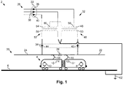
- Fig. 1 shows in a schematic view a catenary system 2 that supplies a train 4 with electrical energy.
- the train 4 that is guided on a rail track 6 is driven by a first electric motor 8 and a second electric motor 10.
- the first electric motor 8 can be supplied with electric energy by a first accumulator 12, while the second electric motor 10 can supplied with electric energy by a second accumulator 14.
- the first accumulator 12 is loaded with electric energy via a first pantograph 16, while the second accumulator 14 is loaded via a second pantograph 18.
- both pantographs 16, 18 can get the electric energy to be charged into the accumulators 12, 14 from a catenary 20.
- the catenary 20 is divided into two or more catenary sections 22, 24 that are each electrically separated via a section insulator 26.
- the first pantograph 16 is positioned below the first catenary section 22 and the second patograph 18 is positioned below the second catenary section 24 as shown in Fig. 1 , the first accumulator 12 will be charged via the first catenary section 22, while the second accumulator 14 will be charged via the second catenary section 24.
- Such a scenario can be kept uphold for a comparably long time, like at a terminus of a line, when the train 4 is waiting for its next mission.
- the thought behind the present embodiment is to use the before described scenario to symmetrically take electric energy from a three phase power grid 28 when charging the first and the second accumulator 12, 14.
- the three phase power grid 28 provides a three phase current 30 feeding a phase converter 32.
- the phase converter 32 is exemplary embodied as Scott transformer and transforms the three phase current 30 into a two phase current 34 that itself supplies the catenary 20.
- the three phase current 30 that is input into the phase converter 32 includes a first phase input current 36, a second phase input current 38 and a third phase input current 40, while the phase converter 32 outputs a first phase output current 42 and a second phase output current 44.
- the phase converter 32 includes a first transformator 46 with a first input inductance 48 and a first output inductance 50 and further a second transformator 52 with a second input inductance 54 and a second output inductance 56. All inductances 48 to 56 are electrotechnically equal and wound with an equal inductance winding amount.
- the first phase input current 36 is input into the first input inductance 48 at a first center tap 58 that is located at an winding amount of ⁇ 3/2 of the complete winding amount of the first input inductance 48.
- the side opposite of the first center tap 58 of the first input inductance 48 is connected to a second center tap 60 in the middle of the second input inductance 54.
- the first output inductances 50 is connected between the first catenary 22 and ground 62
- the second output inductances 56 is connected between the second catenary 24 and ground 62 in such a way, that both output inductances 50, 56 are connected to each other in a starshape way.
- the train 4 includes a control device 64, which structure is shown in Fig. 2 .
- This structure is only provided as example and should not limit the basic idea behind the invention in any way.
- the control device 64 measures the converted two phase current 34 and determines, whether the converted two phase current 34 results from an unsymmetric three phase current 30. In case, the converted two phase current 34 results from an unsymmetric three phase current 30, the control device 64 amends the two phase current 34 to symmetrise the three phase current 30.
- the control device 64 therefore includes a first measuring equipment 66 for measuring the first phase output current 42 and a second measuring equipment 68 for measuring the second phase output current 44.
- the first measuring equipment 66 outputs a first current value 70 that reflects a measuring value for the first phase output current 42.
- the first current value 70 can reflect the first phase output current 42 in an arbitrary way, like as mean value over a predefined time, as effective value over a predefined time, as instantaneous value, etc.
- the second measuring equipment 68 outputs a second current value 72 that reflects a measuring value for the second phase output current 44.
- the control device 64 further includes a comparison equipment 74 that is adapted to compare measured current values 70, 72 and to output a first adjustment signal 76 or a second adjustment signal 78 that controls the above mentioned symmetrisation.
- the comparison equipment 74 includes a comparison element 80 that is embodied as subtraction element in Fig. 2 .
- the output of the comparison element is a comparison value 82 that indicates with its sign, which of the measured current values 70, 72 is larger and based on its absolute value the difference between the measured current values 70, 72.
- the comparison equipment 74 further includes a determination element 86 that defines based on a reliability value 84.
- the reliability value 84 is a limit for the before mentioned absolute value of the comparison value 82, that is between the measured current values 70, 72, upon which an unsymmetrie in the three phase current 30 raises for example security criteria of the provider of the three phase current 30.
- the sign in the comparison value 82 indicates whether the the first measured current value 70 or the second measured current value 72 is too high to keep within the security criteria of the provider of the three phase current 30.
- the determination element 86 outputs either the first adjustment signal 76 or the second adjustment signal 78.
- the control device 64 further includes a first control element 88 in the path of the first phase output current 42 and a second control element 90 in the path of the second phase output current 44.
- These control elements 88, 90 can be exemplary embodied as current limiters that limit the respective phase output current 42, 44 based on the first or second adjustment signal 76, 78 in a way, that the security criteria of the provider of the three phase current 30 is kept.
- the comparison value 82 indicates that the first phase output current 42 is too high, the comparison equipment 74 controls with the first adjustment signal 76 the first control element 88 to limit the first phase output current 42 to a current value 70 that is within the security criteria or technical connection condition of the provider of the three phase current 30.
- the comparison equipment 74 controls with the second adjustment signal 78 the second control element 90 to limit the second phase output current 44 to a current value 72 that is within the security criteria of the provider of the three phase current 30.
- the accumulators 12, 14 in the train 4 can be charged with a symmetric current drain from the three phase power grid 28, if rectified.
- control device 64 of Fig. 2 The disadvantage of the control device 64 of Fig. 2 is that an unbalanced current drain from the three phase power grid 28 will usually occur, if either the first accumulator 12 or the second accumulator 14 is fully charged, such that the charging current of the respectively other accumulator 14, 12 must be limited in order to respect the technical connection conditions.
- an alternative control device 64' is proposed in Fig. 3 .
- This alternative control device 64' includes instead of current limiters switches as control elements 88, 90 that guide the output phase current 42, 44 that is too high according to the before mentioned criteria to an auxiliary load 92.
- the auxiliary load 92 can be a third accumulator or any other electric energy consumer that is able to adsorb the exceeding electric energy.
- Figs. 2 and 3 it is assumed that the described control devices 64 are located in one single railcar of the train 4. However, the invention can also be practiced on different railcars of the train 4 or even on different trains. To describe this possibility in further detail, the first measuring equipment 66 and the first control element 88 forms a first current control equipment 94, whereas the second measuring equipment 66 and the second control element 90 forms a second current control equipment 96.
- FIG. 4 An embodiment to implement the invention on different railcars of the train 4 is shown in Fig. 4 .
- the comparison equipment 74 and the first current control equipment 94 can be located in a first railcar 98 of the train 4 with the first pantograph 16.
- the second current control equipment 96 can be located in a second railcar 100 of the train 4 with the second panthograph 18.
- the auxiliary load 92 can be provided either in one of the railcars 98, 100 or stationary regarded to the train 4. An electric power line between the railcars 98, 100 and the auxiliary load 92 must be installed in an application dependent way.
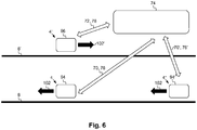
- the first current control equipment 94 can be located in the train 4 with the first pantograph 16, wherein the second current control equipment 96 can be located in another train 4' with the second pantograph 18 that is located on another track 6' and takes electric energy from another catenary 20'.
- the section insulator 26 will thus be the air between the two catenaries 20, 20'.
- the comparison equipment 74 can be located in one of the trains 4, 4', it is also possible to locate the comparison equipment 74 at a common coordination center. As described in line with Fig. 4 , the auxiliary load 92 can also be located in one of the trains 4, 4' or stationary to all trains 4, 4'.
- Locating the comparison equipment 74 at a common coordination center allows further controlling the symmetric current drain from the three phase power grid 28 even for running trains 4, 4' by guiding surplus electric current to other trains running on a same track. This should be explained in fore detail by referring to Fig. 6 .
Landscapes
- Engineering & Computer Science (AREA)
- Power Engineering (AREA)
- Life Sciences & Earth Sciences (AREA)
- Sustainable Development (AREA)
- Sustainable Energy (AREA)
- Transportation (AREA)
- Mechanical Engineering (AREA)
- Electric Propulsion And Braking For Vehicles (AREA)
- Supply And Distribution Of Alternating Current (AREA)
- Control Of Electrical Variables (AREA)
Priority Applications (5)
| Application Number | Priority Date | Filing Date | Title |
|---|---|---|---|
| EP19020066.7A EP3696009B1 (fr) | 2019-02-12 | 2019-02-12 | Procédé de symétrisation d'un courant triphasé |
| CN202020138758.2U CN212267269U (zh) | 2019-02-12 | 2020-01-21 | 使三相电流对称的控制设备、列车及接触网系统 |
| CN202080014565.9A CN113453947A (zh) | 2019-02-12 | 2020-02-11 | 使三相电流对称的方法 |
| PCT/IB2020/051058 WO2020165745A1 (fr) | 2019-02-12 | 2020-02-11 | Procédé de symétrisation d'un courant triphasé |
| TW109104417A TWI797423B (zh) | 2019-02-12 | 2020-02-12 | 使三相電流對稱的方法及控制設備 |
Applications Claiming Priority (1)
| Application Number | Priority Date | Filing Date | Title |
|---|---|---|---|
| EP19020066.7A EP3696009B1 (fr) | 2019-02-12 | 2019-02-12 | Procédé de symétrisation d'un courant triphasé |
Publications (3)
| Publication Number | Publication Date |
|---|---|
| EP3696009A1 true EP3696009A1 (fr) | 2020-08-19 |
| EP3696009B1 EP3696009B1 (fr) | 2024-09-04 |
| EP3696009C0 EP3696009C0 (fr) | 2024-09-04 |
Family
ID=65433432
Family Applications (1)
| Application Number | Title | Priority Date | Filing Date |
|---|---|---|---|
| EP19020066.7A Active EP3696009B1 (fr) | 2019-02-12 | 2019-02-12 | Procédé de symétrisation d'un courant triphasé |
Country Status (4)
| Country | Link |
|---|---|
| EP (1) | EP3696009B1 (fr) |
| CN (2) | CN212267269U (fr) |
| TW (1) | TWI797423B (fr) |
| WO (1) | WO2020165745A1 (fr) |
Families Citing this family (4)
| Publication number | Priority date | Publication date | Assignee | Title |
|---|---|---|---|---|
| EP3696009B1 (fr) * | 2019-02-12 | 2024-09-04 | Furrer + Frey AG | Procédé de symétrisation d'un courant triphasé |
| CN112152531B (zh) * | 2020-09-09 | 2022-08-12 | 北京罗克维尔斯科技有限公司 | 三相电机电流对称性检测方法、装置、控制器及车辆 |
| CN113051708B (zh) * | 2021-02-03 | 2022-10-25 | 安徽大学 | 一种基于能量平衡的电窑炉电能质量特性分析模型的建立方法 |
| CN113346765B (zh) * | 2021-05-21 | 2024-08-16 | 西安交通大学 | 一种基于平衡变压器的同相供电装置拓扑结构和控制方法 |
Citations (4)
| Publication number | Priority date | Publication date | Assignee | Title |
|---|---|---|---|---|
| US3278825A (en) | 1962-11-01 | 1966-10-11 | United Aircraft Corp | Static inverter utilizing a modified scott-t transformer |
| WO2014101282A1 (fr) * | 2012-12-28 | 2014-07-03 | 西南交通大学 | Alimentation en courant en phase de type combiné monophasé et triphasé et dispositif de transformation |
| EP2766972A1 (fr) * | 2011-10-14 | 2014-08-20 | ABB Technology AG | Convertisseur multi-niveaux et procédé de commande d'un convertisseur multi-niveaux comprenant l'équilibrage des tensions des cellules |
| CN104527462A (zh) * | 2014-11-24 | 2015-04-22 | 西南交通大学 | 一种基于既有牵引供电系统改进的并联型贯通式牵引供电系统 |
Family Cites Families (10)
| Publication number | Priority date | Publication date | Assignee | Title |
|---|---|---|---|---|
| US7903433B2 (en) * | 2007-12-26 | 2011-03-08 | Texas Instruments Incorporated | Current balancing for multi-phase converters |
| CN101453171B (zh) * | 2008-09-12 | 2011-09-28 | 清华大学 | 基于变压器串联多重化和链式结构的统一电能质量控制器 |
| CN101882788B (zh) * | 2009-09-14 | 2013-09-18 | 株洲变流技术国家工程研究中心有限公司 | 一种重载铁路长供电臂末端网压提高方法及装置 |
| GB2491652A (en) * | 2011-06-10 | 2012-12-12 | Bombardier Transp Gmbh | System and Method for Transferring Electric Energy to a Vehicle Using a Plurality of Segments of a Conductor Arrangement |
| CN102991363B (zh) * | 2012-12-07 | 2015-08-05 | 南车株洲电力机车有限公司 | 一种城轨车辆的蓄电池与受电弓牵引供电系统 |
| JP5735061B2 (ja) * | 2013-08-12 | 2015-06-17 | 株式会社東芝 | 電車給電システム |
| TWI500245B (zh) * | 2013-11-08 | 2015-09-11 | Nat Inst Chung Shan Science & Technology | Power conversion harmonic control system |
| JP6514070B2 (ja) * | 2015-08-25 | 2019-05-15 | 東芝インフラシステムズ株式会社 | 鉄道用電力補償装置 |
| CN108448630B (zh) * | 2018-04-24 | 2022-06-28 | 上海电力学院 | 基于单周期和双电流环控制的z源逆变器并网控制方法 |
| EP3696009B1 (fr) * | 2019-02-12 | 2024-09-04 | Furrer + Frey AG | Procédé de symétrisation d'un courant triphasé |
-
2019
- 2019-02-12 EP EP19020066.7A patent/EP3696009B1/fr active Active
-
2020
- 2020-01-21 CN CN202020138758.2U patent/CN212267269U/zh active Active
- 2020-02-11 CN CN202080014565.9A patent/CN113453947A/zh active Pending
- 2020-02-11 WO PCT/IB2020/051058 patent/WO2020165745A1/fr not_active Ceased
- 2020-02-12 TW TW109104417A patent/TWI797423B/zh active
Patent Citations (4)
| Publication number | Priority date | Publication date | Assignee | Title |
|---|---|---|---|---|
| US3278825A (en) | 1962-11-01 | 1966-10-11 | United Aircraft Corp | Static inverter utilizing a modified scott-t transformer |
| EP2766972A1 (fr) * | 2011-10-14 | 2014-08-20 | ABB Technology AG | Convertisseur multi-niveaux et procédé de commande d'un convertisseur multi-niveaux comprenant l'équilibrage des tensions des cellules |
| WO2014101282A1 (fr) * | 2012-12-28 | 2014-07-03 | 西南交通大学 | Alimentation en courant en phase de type combiné monophasé et triphasé et dispositif de transformation |
| CN104527462A (zh) * | 2014-11-24 | 2015-04-22 | 西南交通大学 | 一种基于既有牵引供电系统改进的并联型贯通式牵引供电系统 |
Also Published As
| Publication number | Publication date |
|---|---|
| TW202038542A (zh) | 2020-10-16 |
| CN113453947A (zh) | 2021-09-28 |
| TWI797423B (zh) | 2023-04-01 |
| WO2020165745A1 (fr) | 2020-08-20 |
| EP3696009B1 (fr) | 2024-09-04 |
| CN212267269U (zh) | 2021-01-01 |
| EP3696009C0 (fr) | 2024-09-04 |
Similar Documents
| Publication | Publication Date | Title |
|---|---|---|
| WO2020165745A1 (fr) | Procédé de symétrisation d'un courant triphasé | |
| US8508186B2 (en) | Charging system for transportation system without contact wire | |
| CN105790274A (zh) | 一种贯通供电系统变流器型牵引变电所潮流调控装置及其调控方法 | |
| JP2010215013A (ja) | 鉄道車両システム | |
| US12434642B2 (en) | Power supply system and method | |
| KR20120051459A (ko) | 교류 전력을 이용한 전기차량 충전시스템 | |
| US20210129874A1 (en) | Operation of Rail Vehicles to Limit Power Peaks in an Electrical Supply | |
| EP2915693B1 (fr) | Dispositif de gestion d'énergie et système de gestion d'énergie | |
| CN105691244B (zh) | 一种电气化铁路贯通供电的系统空载监控方法 | |
| EP3556604B1 (fr) | Dispositif d'alimentation de bâtiment de gare | |
| CN205407265U (zh) | 一种贯通供电系统变流器型牵引变电所潮流调控装置 | |
| US11407324B2 (en) | Charging systems for charging electrical energy storage devices of electric vehicles and associated methods | |
| KR20110113125A (ko) | 직류 전력시스템 전력을 이용한 전기차량 충전시스템 | |
| CN101959710B (zh) | 用于有轨车辆的储能器系统 | |
| CN108944578B (zh) | 一种用于列车的供电装置、供电方法及列车 | |
| KR102070897B1 (ko) | 전기차 충전기 계통 연계 단말장치 및 계통 연계 방법 | |
| WO2020077688A1 (fr) | Train à lévitation magnétique et son procédé de commande de traction | |
| CN205395812U (zh) | 一种电气化铁路贯通供电的系统空载监控装置 | |
| EP3480049A1 (fr) | Véhicule électrique à courant alternatif | |
| Kilter et al. | Assessment of transmission network voltage unbalance in connection of high-speed electrical railway connection | |
| Griffin | Methods of improving the voltage regulation on 25 kV electric railways | |
| JP6548796B1 (ja) | 電力変換システム、交通システム及び電力変換方法 | |
| Vlasov et al. | Joint operation of 6-and 12-pulse rectifier units when modernizing traction substations | |
| Singh et al. | Study of Unbalance Reduction in 25kV AC Traction System by Different Transformer Configurations | |
| JPS60124538A (ja) | 電気鉄道用変電所の制御方法 |
Legal Events
| Date | Code | Title | Description |
|---|---|---|---|
| PUAI | Public reference made under article 153(3) epc to a published international application that has entered the european phase |
Free format text: ORIGINAL CODE: 0009012 |
|
| STAA | Information on the status of an ep patent application or granted ep patent |
Free format text: STATUS: THE APPLICATION HAS BEEN PUBLISHED |
|
| AK | Designated contracting states |
Kind code of ref document: A1 Designated state(s): AL AT BE BG CH CY CZ DE DK EE ES FI FR GB GR HR HU IE IS IT LI LT LU LV MC MK MT NL NO PL PT RO RS SE SI SK SM TR |
|
| AX | Request for extension of the european patent |
Extension state: BA ME |
|
| STAA | Information on the status of an ep patent application or granted ep patent |
Free format text: STATUS: REQUEST FOR EXAMINATION WAS MADE |
|
| 17P | Request for examination filed |
Effective date: 20210219 |
|
| RBV | Designated contracting states (corrected) |
Designated state(s): AL AT BE BG CH CY CZ DE DK EE ES FI FR GB GR HR HU IE IS IT LI LT LU LV MC MK MT NL NO PL PT RO RS SE SI SK SM TR |
|
| STAA | Information on the status of an ep patent application or granted ep patent |
Free format text: STATUS: EXAMINATION IS IN PROGRESS |
|
| 17Q | First examination report despatched |
Effective date: 20211202 |
|
| GRAP | Despatch of communication of intention to grant a patent |
Free format text: ORIGINAL CODE: EPIDOSNIGR1 |
|
| STAA | Information on the status of an ep patent application or granted ep patent |
Free format text: STATUS: GRANT OF PATENT IS INTENDED |
|
| INTG | Intention to grant announced |
Effective date: 20240404 |
|
| GRAS | Grant fee paid |
Free format text: ORIGINAL CODE: EPIDOSNIGR3 |
|
| GRAA | (expected) grant |
Free format text: ORIGINAL CODE: 0009210 |
|
| STAA | Information on the status of an ep patent application or granted ep patent |
Free format text: STATUS: THE PATENT HAS BEEN GRANTED |
|
| AK | Designated contracting states |
Kind code of ref document: B1 Designated state(s): AL AT BE BG CH CY CZ DE DK EE ES FI FR GB GR HR HU IE IS IT LI LT LU LV MC MK MT NL NO PL PT RO RS SE SI SK SM TR |
|
| REG | Reference to a national code |
Ref country code: GB Ref legal event code: FG4D |
|
| REG | Reference to a national code |
Ref country code: CH Ref legal event code: EP |
|
| REG | Reference to a national code |
Ref country code: IE Ref legal event code: FG4D |
|
| REG | Reference to a national code |
Ref country code: DE Ref legal event code: R096 Ref document number: 602019058171 Country of ref document: DE |
|
| U01 | Request for unitary effect filed |
Effective date: 20241002 |
|
| U07 | Unitary effect registered |
Designated state(s): AT BE BG DE DK EE FI FR IT LT LU LV MT NL PT RO SE SI Effective date: 20241024 |
|
| PG25 | Lapsed in a contracting state [announced via postgrant information from national office to epo] |
Ref country code: PL Free format text: LAPSE BECAUSE OF FAILURE TO SUBMIT A TRANSLATION OF THE DESCRIPTION OR TO PAY THE FEE WITHIN THE PRESCRIBED TIME-LIMIT Effective date: 20240904 Ref country code: GR Free format text: LAPSE BECAUSE OF FAILURE TO SUBMIT A TRANSLATION OF THE DESCRIPTION OR TO PAY THE FEE WITHIN THE PRESCRIBED TIME-LIMIT Effective date: 20241205 |
|
| PG25 | Lapsed in a contracting state [announced via postgrant information from national office to epo] |
Ref country code: HR Free format text: LAPSE BECAUSE OF FAILURE TO SUBMIT A TRANSLATION OF THE DESCRIPTION OR TO PAY THE FEE WITHIN THE PRESCRIBED TIME-LIMIT Effective date: 20240904 |
|
| PG25 | Lapsed in a contracting state [announced via postgrant information from national office to epo] |
Ref country code: ES Free format text: LAPSE BECAUSE OF FAILURE TO SUBMIT A TRANSLATION OF THE DESCRIPTION OR TO PAY THE FEE WITHIN THE PRESCRIBED TIME-LIMIT Effective date: 20240904 Ref country code: RS Free format text: LAPSE BECAUSE OF FAILURE TO SUBMIT A TRANSLATION OF THE DESCRIPTION OR TO PAY THE FEE WITHIN THE PRESCRIBED TIME-LIMIT Effective date: 20241204 |
|
| PG25 | Lapsed in a contracting state [announced via postgrant information from national office to epo] |
Ref country code: RS Free format text: LAPSE BECAUSE OF FAILURE TO SUBMIT A TRANSLATION OF THE DESCRIPTION OR TO PAY THE FEE WITHIN THE PRESCRIBED TIME-LIMIT Effective date: 20241204 Ref country code: PL Free format text: LAPSE BECAUSE OF FAILURE TO SUBMIT A TRANSLATION OF THE DESCRIPTION OR TO PAY THE FEE WITHIN THE PRESCRIBED TIME-LIMIT Effective date: 20240904 Ref country code: HR Free format text: LAPSE BECAUSE OF FAILURE TO SUBMIT A TRANSLATION OF THE DESCRIPTION OR TO PAY THE FEE WITHIN THE PRESCRIBED TIME-LIMIT Effective date: 20240904 Ref country code: GR Free format text: LAPSE BECAUSE OF FAILURE TO SUBMIT A TRANSLATION OF THE DESCRIPTION OR TO PAY THE FEE WITHIN THE PRESCRIBED TIME-LIMIT Effective date: 20241205 Ref country code: ES Free format text: LAPSE BECAUSE OF FAILURE TO SUBMIT A TRANSLATION OF THE DESCRIPTION OR TO PAY THE FEE WITHIN THE PRESCRIBED TIME-LIMIT Effective date: 20240904 |
|
| U20 | Renewal fee for the european patent with unitary effect paid |
Year of fee payment: 7 Effective date: 20250213 |
|
| PG25 | Lapsed in a contracting state [announced via postgrant information from national office to epo] |
Ref country code: IS Free format text: LAPSE BECAUSE OF FAILURE TO SUBMIT A TRANSLATION OF THE DESCRIPTION OR TO PAY THE FEE WITHIN THE PRESCRIBED TIME-LIMIT Effective date: 20250104 |
|
| PG25 | Lapsed in a contracting state [announced via postgrant information from national office to epo] |
Ref country code: SM Free format text: LAPSE BECAUSE OF FAILURE TO SUBMIT A TRANSLATION OF THE DESCRIPTION OR TO PAY THE FEE WITHIN THE PRESCRIBED TIME-LIMIT Effective date: 20240904 |
|
| PG25 | Lapsed in a contracting state [announced via postgrant information from national office to epo] |
Ref country code: SK Free format text: LAPSE BECAUSE OF FAILURE TO SUBMIT A TRANSLATION OF THE DESCRIPTION OR TO PAY THE FEE WITHIN THE PRESCRIBED TIME-LIMIT Effective date: 20240904 |
|
| PLBE | No opposition filed within time limit |
Free format text: ORIGINAL CODE: 0009261 |
|
| STAA | Information on the status of an ep patent application or granted ep patent |
Free format text: STATUS: NO OPPOSITION FILED WITHIN TIME LIMIT |
|
| 26N | No opposition filed |
Effective date: 20250605 |
|
| PG25 | Lapsed in a contracting state [announced via postgrant information from national office to epo] |
Ref country code: MC Free format text: LAPSE BECAUSE OF FAILURE TO SUBMIT A TRANSLATION OF THE DESCRIPTION OR TO PAY THE FEE WITHIN THE PRESCRIBED TIME-LIMIT Effective date: 20240904 |
|
| PGFP | Annual fee paid to national office [announced via postgrant information from national office to epo] |
Ref country code: CZ Payment date: 20251210 Year of fee payment: 8 |
|
| REG | Reference to a national code |
Ref country code: CH Ref legal event code: U11 Free format text: ST27 STATUS EVENT CODE: U-0-0-U10-U11 (AS PROVIDED BY THE NATIONAL OFFICE) Effective date: 20260301 |
|
| U20 | Renewal fee for the european patent with unitary effect paid |
Year of fee payment: 8 Effective date: 20260206 |
|
| PGFP | Annual fee paid to national office [announced via postgrant information from national office to epo] |
Ref country code: GB Payment date: 20260126 Year of fee payment: 8 |
|
| PGFP | Annual fee paid to national office [announced via postgrant information from national office to epo] |
Ref country code: NO Payment date: 20260206 Year of fee payment: 8 Ref country code: IE Payment date: 20260210 Year of fee payment: 8 |
|
| PGFP | Annual fee paid to national office [announced via postgrant information from national office to epo] |
Ref country code: CH Payment date: 20260301 Year of fee payment: 8 |