EP3696134A9 - Chariot de manutention doté d'un module de poste de travail de conducteur doté d'une plate-forme de station debout pour conducteur - Google Patents
Chariot de manutention doté d'un module de poste de travail de conducteur doté d'une plate-forme de station debout pour conducteur Download PDFInfo
- Publication number
- EP3696134A9 EP3696134A9 EP20155079.5A EP20155079A EP3696134A9 EP 3696134 A9 EP3696134 A9 EP 3696134A9 EP 20155079 A EP20155079 A EP 20155079A EP 3696134 A9 EP3696134 A9 EP 3696134A9
- Authority
- EP
- European Patent Office
- Prior art keywords
- spring
- driver
- industrial truck
- truck according
- workstation module
- Prior art date
- Legal status (The legal status is an assumption and is not a legal conclusion. Google has not performed a legal analysis and makes no representation as to the accuracy of the status listed.)
- Granted
Links
Images


Classifications
-
- B—PERFORMING OPERATIONS; TRANSPORTING
- B66—HOISTING; LIFTING; HAULING
- B66F—HOISTING, LIFTING, HAULING OR PUSHING, NOT OTHERWISE PROVIDED FOR, e.g. DEVICES WHICH APPLY A LIFTING OR PUSHING FORCE DIRECTLY TO THE SURFACE OF A LOAD
- B66F9/00—Devices for lifting or lowering bulky or heavy goods for loading or unloading purposes
- B66F9/06—Devices for lifting or lowering bulky or heavy goods for loading or unloading purposes movable, with their loads, on wheels or the like, e.g. fork-lift trucks
- B66F9/075—Constructional features or details
- B66F9/0759—Details of operating station, e.g. seats, levers, operator platforms, cabin suspension
Definitions
- the invention relates to an industrial truck with a driver's workstation module which comprises a driver's platform for a standing operator and which is supported on a vehicle frame of the industrial truck in a sprung manner by means of a spring device.
- Such industrial trucks with a driver's workplace module having a driver's platform are operated by an operator standing on the driver's platform.
- conical spiral spring In order to achieve a non-linear spring stiffness of the spring device of an operator platform, it is also possible to use a conical spiral spring as the spring device.
- conical coil springs have a non-linear spring characteristic in which the spring stiffness changes as a function of the spring travel.
- the disadvantage of these conical spiral springs is the complexity of the conical spiral spring and the associated high manufacturing costs of a conical spiral spring and the need to at the same time having to change the preload in order to be able to change the spring stiffness.
- the present invention is based on the object of providing an industrial truck of the type mentioned at the outset, which has a sprung driver's workplace module, in which the suspension stiffness of the driver's workplace module can be adjusted in a simple and cost-effective manner and continuously.
- the spring device for adapting and setting the suspension stiffness of the spring workstation module is arranged on the industrial truck so that it can be adjusted in alignment, with an adaptation and setting of the spring stiffness of the spring workstation module being achieved by changing the alignment of the spring device.
- alignment is to be understood here as the orientation of the effective direction of the spring device.
- the suspension stiffness of the driver's workplace module can be continuously changed in a simple and inexpensive manner using a simply constructed and inexpensive spring device and the suspension behavior of the driver's workplace module to the body weight of the operator and / or can be adapted to the unevenness of the floor and thus the road surface conditions prevailing in the area of use of the industrial truck.
- a simply constructed spring device can be used, since the change in the suspension stiffness is not made by a complex spring device or by changing the geometry of the spring device, for example an air spring or a conical spiral spring, but rather the change in the suspension rigidity takes place solely through a corresponding change in the alignment of the spring device and the spring device only needs to be arranged in a corresponding alignment in order to achieve a desired suspension rigidity of the driver's workstation module.
- the spring device has a linear, i.e. has an identical or fixed spring constant and is designed as a helical spring (helical spring), in particular a cylindrical helical spring, in particular a cylindrical helical compression spring or a cylindrical helical tension spring.
- a helical spring helical spring
- cylindrical helical spring in particular a cylindrical helical compression spring or a cylindrical helical tension spring.
- the suspension stiffness of the driver's workstation module can be changed in a simple and inexpensive way and the suspension behavior of the driver's workstation module to the body weight of the Operator and / or be adapted to the unevenness of the floor in the area where the truck is used.
- the spring device is arranged between a first spring holder and a second spring holder, the first spring holder being arranged on the driver's workstation module so that it can pivot about a horizontal pivot axis and the second spring holder is arranged on the vehicle frame so that it can pivot about a horizontal pivot axis.
- spring holders of this type which are arranged on the driver's workstation module and on the vehicle frame so that they can each pivot about a horizontal pivot axis, the alignment of the spring device can be easily adjusted on the industrial truck in order to adapt and adjust the suspension stiffness of the spring device.
- the first spring holder and / or the second spring holder are in operative connection with an adjusting device with which the alignment of the spring device for adapting and setting the suspension stiffness of the driver's workplace can be adjusted.
- an adjustment device With an adjustment device, the first spring holder or the second spring holder can be pivoted about the corresponding horizontal pivot axis in a simple manner, and the alignment of the spring device can thereby be changed and adjusted.
- the adjusting device is designed as an adjusting screw.
- the first spring holder or the second spring holder can be pivoted about the corresponding horizontal pivot axis in a simple manner and the alignment of the spring device can be continuously changed and adjusted.
- the setting device is arranged on the driver's workstation module and is in operative connection with the first spring holder, the first spring holder being pivotable about the horizontal pivot axis with the setting device for adapting and setting the spring stiffness of the spring device.
- the setting device can be actuated manually, in particular by means of a handwheel or a hand lever, or electrically, in particular by means of an electric motor.
- the force to be applied to the setting device in order to change the alignment of the spring device and thereby the suspension stiffness of the driver's workstation module by pivoting the first spring holder or the second spring holder about the corresponding horizontal pivot axis is low, so that the setting device can be operated manually, e.g. Hand lever, can be operated by the operator or electrically, for example by means of an electric motor, can be operated.
- the second spring holder has a pot-like housing in which the spring device is arranged and which is arranged in the upper area by means of an articulated connection, in particular a pin, on the vehicle frame so as to be pivotable about the horizontal pivot axis and in the lower area a lower spring plate forms on which the spring device rests.
- the spring device can be supported on a lower spring plate with little space requirement.
- the first spring holder has a retaining bracket which is arranged on the driver's workstation module so that it can pivot about the horizontal pivot axis by means of an articulated connection, in particular a pin, and which is in operative connection with an upper spring plate on which the spring device rests.
- the spring device can be supported on an upper spring plate with little space requirement.
- the upper spring plate is connected to an actuating rod which is arranged on the retaining bracket so that it can pivot about a horizontal pivot axis.
- an actuating rod With such an actuating rod, the upper spring plate can be attached to the retaining bracket in a simple manner.
- the upper spring plate can be arranged adjustably on the actuating rod. If the upper spring plate is adjustably arranged on the actuating rod, an adaptation of the spring preload of the spring device arranged and clamped between the lower spring plate and the upper spring plate can be achieved in a simple manner.
- the actuating rod is arranged pivotably about the horizontal pivot axis on the retaining bracket by means of an articulated connection, in particular a pin, the articulated connection being arranged below the lower spring plate.
- the actuating rod is arranged within the spring device and the lower spring plate is provided with a recess through which the actuating rod extends. This allows a space-saving arrangement of the actuating rod within the Spring device can be achieved and a guide between the actuating rod and the lower spring plate can be achieved.
- the driver's workstation module is suspended from the vehicle frame by means of a double-link guide, in particular a parallelogram suspension.
- the movable suspension of the driver's workplace module on the vehicle frame by means of a parallelogram suspension makes it possible in a simple manner to achieve a pure vertical movement or essentially vertical movement of the sprung driver's platform and to minimize or avoid the rotation of the driver's platform, which results in a high level of comfort for the operator standing on the sprung driver's platform and the spring device can be actuated in a simple manner.
- a display device for displaying the set suspension stiffness of the driver's workstation module. This makes it possible in a simple manner to visually indicate to the operator the set suspension stiffness of the spring device and thereby make it easier for the operator to set the suspension stiffness of the spring device.
- the display device has a pointer which is operatively connected to the first spring holder and which can be moved along a scale for the suspension rigidity of the driver's workstation module.
- a pointer coupled to the first pen holder, which can be moved along a scale, a corresponding movement of the pointer relative to the scale can be achieved in a simple manner when the first pen holder is pivoted about the horizontal pivot axis, and thus the operator can obtain the currently set stiffness of the spring device are displayed.
- the driver's workstation module comprises a backrest in addition to the driver's stand platform.
- the operator standing on the driver's platform can lean with his back against such a backrest, which increases the comfort for the operator.
- the arrangement of the backrest and the Driver's platform on the driver's workstation module is achieved that the backrest and the driver's platform are sprung by means of the spring device and there is no relative movement between the backrest and the driver's platform, whereby a high level of suspension comfort is achieved.
- the backrest can be provided with a driver's seat, in particular a folding seat.
- a driver's seat makes it possible for the operator located in the driver's workplace module to operate the industrial truck in an operating mode standing on the driver's platform or in an operating mode sitting on the driver's seat.
- the spring device can be used to protect the operator from oscillations, vibrations and shocks during operation of the industrial truck by means of the spring device.
- the industrial truck can be designed as a lift truck or order picker. Particular advantages arise when the industrial truck is designed as a tractor.
- An industrial truck designed as a tractor that usually covers long distances in operation on a company site and is driven both inside and outside halls and therefore with different road surface conditions and usually drives over small obstacles, for example lane edges or curbs, during operation, is supported by a Operator operated standing or sitting for long periods of time.
- the sprung driver's workplace module according to the invention which enables the suspension behavior of the driver's workplace module to be easily adapted to the body weight of the operator and to the condition of the roadway, improved comfort for the operator can be achieved with little construction effort in a tractor operated while standing or sitting.
- an industrial truck 1 of the prior art with a driver's workstation module F which comprises a driver's platform 8 for a standing operator P, is shown in a schematic diagram.
- the driver's workstation module F is supported on a vehicle frame 2 of the industrial truck 1 in a sprung manner by means of a spring device 12.
- the spring device 12 of the Figures 1a, 1b can only be changed and set in the preload PL1, PL2, but not in the spring stiffness S1.
- a screw element can be used, for example, which presses the spring device 12 together.
- the spring device 12 is set to a low preload PL1 in which Figure 1b the spring device 12 is set to a high preload PL2.
- the spring device 12 has the Figures 1a and 1b the same spring stiffness S1. If no operator P is standing on the driver's platform 8, the Figures 1a, 1b the driver's platform 8 is urged upwards by the spring device 12 in contact with an upper stop E on the vehicle frame 2.
- the spring stiffness S1 corresponds to a value of 5 kg / mm
- the preload PL1 in the Figure 1a 5mm and the preload PL2 in the Figure 1b 7th , 5 mm results in the Figure 1a for a light operator P with a body weight of 50KG a stroke H1 of 5mm of the driver's platform 8 and in the Figure 1b for a heavy operator P with a body weight of 100 kg, a stroke H2 of 12.5 mm of the driver's platform 8.
- the value of the spring stiffness S1 is not optimized for the body weight of an operator P.
- an industrial truck 1 of the prior art with a driver's workstation module F which comprises a driver's standing platform 8 for a standing operator P, is shown in each case in a schematic diagram.
- the driver's workstation module F is supported on a vehicle frame 2 of the industrial truck 1 in a sprung manner by means of a spring device 12.
- the spring device 12 of the Figures 1c, 1d can be changed and adjusted both in the preload PL1, PL2 and in the spring stiffness S1, S2.
- the spring device 12 is set to a low preload PL1 and to a low spring stiffness S1, in which Figure 1d the spring device 12 is set to a high preload PL2 and to a high spring stiffness S2.
- FIG Figure 1d stands a heavy operator P with a body weight of for example 100 KG on the driver's platform 8. If no operator P is standing on the driver's platform 8, the Figures 1c, 1d the driver's platform 8 is urged upwards by the spring device 12 in contact with an upper stop E on the vehicle frame 2.
- the Figures 1c and 1d it is made possible by changing the spring stiffness to the value S2 for operators P with different body weights standing on the operator platform 8, to achieve an equally large stroke H1 in the vertical direction z, ie an equally large deflection of the operator platform 8.
- the spring stiffness S1 corresponds to a value of 5 kg / mm
- the spring stiffness S2 corresponds to a value of 8 kg / mm
- the preload PL1 in the Figure 1c 5mm and the preload PL2 in the Figure 1d 7th , 5 mm results in the Figure 1c for a light operator P with a body weight of 50KG, a stroke H1 of 5mm of the driver's platform 8 and in the Figure 1d for a heavy operator P with a body weight of 100KG also a stroke H1 of 5mm of the driver's platform 8.
- the spring stiffness of the spring device 12 can be adapted to the respective body weight of the operator P.
- the spring device 12 is arranged in the same orientation, ie orientation of the effective direction.
- the spring device 12 can be designed, for example, as an air spring and the adjustment of the spring stiffness S1, S2 can be achieved by changing the air pressure in the air spring.
- air springs with adjustable air pressure have a high manufacturing effort and require an air compressor in the industrial truck 1 to change the air pressure, which further increases the manufacturing effort for the sprung driver's workstation module F.
- an industrial truck 1 with a driver's workstation module F which comprises a driver's standing platform 8 for a standing operator P, is shown in a schematic diagram in each case.
- the driver's workstation module F is supported on a vehicle frame 2 of the industrial truck 1 in a sprung manner by means of a spring device 12.
- the spring device 12 of the Figures 1e, 1f is for adapting and setting the suspension stiffness of the driver's workstation module F in the orientation, ie in the orientation of the Direction of action, adjustable on the industrial truck 1.
- the spring device 12 has in the Figures 1e and 1f the same preload PL1 and the same spring stiffness S1, ie in the Figures 1e, 1f the same spring device 12 is installed with unchanged settings (preload, spring stiffness).
- the spring device 12 is arranged in an inclined orientation in which the line of action of the spring device 12 is arranged inclined at an angle ⁇ of, for example, 60 ° relative to the vertical.
- the spring device 12 is arranged in a vertical orientation in which the line of action of the spring device 12 is arranged in the vertical.
- FIG Figure 1f If there is a heavy operator P with a body weight of 100 KG, for example, standing on the driver's platform 8. If no operator P is standing on the driver's platform 8, the Figures 1e, 1f the driver's platform 8 is urged upwards by the spring device 12 in contact with an upper stop E on the vehicle frame 2.
- the spring device 12 By changing the orientation of the spring device 12, it is made possible in a simple manner and at low cost for the spring device 12 to adapt the suspension stiffness of the driver's workplace module F to different body weights of the operators P in order to have the same stroke H1 in the vertical direction for different body weights of the operators P , ie to achieve an equal deflection of the driver's platform 8, since the spring travel x of the spring device 12 which is set under a load and which is arranged in the line of action of the spring device 12 changes with the angle ⁇ .
- the spring travel x of the spring element 12 is only half of the stroke H1 of the operator platform 8.
- the spring travel x of the spring element 12 corresponds to the stroke H1 of the driver's stand platform 8.
- the suspension stiffness of the driver's station module F can be adjusted and it can be achieved that with different body weights of the operators P an equally large stroke H1 of the driver's standing platform 8 is established.
- the result is a low suspension stiffness of the driver's workstation module F for a light operator P and in the vertical alignment of the spring device 12 according to FIG Figure 1f the result is a high level of suspension rigidity of the driver's workstation module F for a heavy operator P.
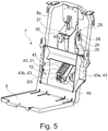
- the Figures 2 to 11 show an industrial truck 1 according to the invention with a sprung driver's workstation module F according to the invention in a constructive embodiment.
- the industrial truck 1 is designed as a tractor in the illustrated embodiment.
- the truck 1 has - as in the Figures 2 to 4 is shown in more detail - a vehicle frame 2 as a supporting component.
- a unit space 4 is formed under a hood, not shown in detail, in which an electrically driven and steerable drive wheel, not shown in detail, is arranged with which the truck 1 is on a Lane supported.
- further units are arranged, for example a power electronics unit for controlling a traction drive motor and a steering motor of the driven and steerable drive wheel.
- a battery compartment 6 is formed on the vehicle frame 2 to accommodate a traction battery which supplies an electric drive system of the industrial truck 1 with electrical energy.
- a driver's workstation module F is arranged on the vehicle frame 2, which comprises a driver's platform 8 for a standing operator on which the operator stands.
- a vertical rear frame wall 9 is arranged on the rear area of the vehicle frame 2 in the longitudinal direction of the industrial truck 1, adjacent to the driver's workstation module F.
- the industrial truck 1 In the rear area of the vehicle frame 2, the industrial truck 1 is supported with running wheels 7 on the roadway.
- the driver's workstation module F is supported on the vehicle frame 2 in a sprung manner by means of a spring device 12.
- the driver's workstation module F is - as in the Figures 2 to 4 is shown in more detail - suspended on the vehicle frame 2 in the vertical direction V by means of a double link guide 10, which is designed for example as a parallelogram suspension.
- the double link guide 10 has, as in Figures 2 to 4 is shown in more detail, two lower links 15, which are each articulated to a first articulated connection G1 on the vehicle frame 2 and to a second articulated connection G2 on the driver's workstation module 8, and at least one upper link 16, which is connected to a third articulated connection G3 the vehicle frame 2 and is articulated to the driver's workstation module F at a fourth articulated connection G4.
- the articulated connections G1 to G4 each have a horizontal pivot axis running in the transverse direction of the vehicle.
- the double-link guide 10 is designed as a parallelogram suspension so that a pure vertical movement of the driver's workstation module F and the driver's stand platform 8 in the vertical direction V is achieved.
- two lower links 15 are provided, which are arranged in the area of the left and right side of the vehicle, and a single upper link 16 is provided, which - viewed in the transverse direction of the vehicle - is arranged essentially in the center.
- the driver's workstation module F is provided with a support section 8a which extends vertically upwards from the driver's stand platform 8.
- the support section 8a is inclined slightly to the vertical V towards the rear towards the rear of the vehicle.
- the spring device 12 by means of which the driver's workstation module F is supported on the vehicle frame 2 in a sprung manner, is - as from the Figures 2 to 4 can be seen - arranged in the vertical direction V above the driver's platform 8.
- the alignment of the spring device 12 is adjustable on the industrial truck 1.
- the structure of the spring device 12, which can be adjusted in alignment on the industrial truck 1, is illustrated below with reference to FIG Figures 4 to 6 described in more detail.
- the spring device 12 is arranged between a first spring holder 20 and a second spring holder 21.
- the first spring holder 20 is on the driver's workstation module F about a horizontal pivot axis D1 ( Figure 4 ) is arranged pivotably.
- the horizontal pivot axis D1 is arranged on the support section 8a of the driver's station module F.
- the second spring holder 21 is arranged on the vehicle frame 2 so as to be pivotable about a horizontal pivot axis D2.
- a holder 22, on which the horizontal pivot axis D2 is formed, is attached to the vehicle frame 2.
- the first spring holder 20 is in operative connection with an adjusting device 25 with which the alignment of the spring device 12 for adapting and adjusting the suspension rigidity of the driver's workstation module F can be adjusted.
- the adjusting device 25 is designed as an adjusting screw 26 in the illustrated embodiment.
- the adjusting device 25, designed as an adjusting screw 26, is rotatably arranged on the driver's workstation module F and is in operative connection with the first spring holder 20.
- the adjusting screw 26 is secured in the longitudinal direction in a bearing block 27, which is arranged on the support section 8a of the driver's workstation module F, and is arranged to be rotatable about the longitudinal axis.
- a nut 28, which is guided in an elongated hole 29 of the first spring holder 20, is arranged on a threaded section of the adjusting screw 26.
- the first spring holder 20 is thus arranged on the driver's workplace module F so that it can pivot about the pivot axis D1 and is held in a corresponding pivoting position on the driver's workplace module F by means of the setting device 25.
- the driver's workstation module F moves in the vertical direction V, for example when the operator gets on the driver's platform 8 and / or when driving over uneven road surfaces
- the setting device 25 can be actuated manually, for example by means of a handwheel 30.
- the handwheel 30 is arranged on the end of the adjusting screw 26 that extends out of the bearing block 27 and can thus be operated by an operator standing on the driver's platform 8.
- the second spring holder 21 has a pot-like housing 40 in which the spring device 12 is arranged.
- the second spring holder 21 is arranged in the upper area by means of an articulated connection 41, for example a pin, on the holder 22 attached to the vehicle frame 2 so as to be pivotable about the horizontal pivot axis D2.
- the second spring holder 21 forms a lower spring plate 42 on which the spring device 12 rests with a lower end.
- the first spring holder 20 has a retaining bracket 43 which is arranged on the driver's workstation module F to be pivotable about the horizontal pivot axis D1 by means of an articulated connection, for example a pin.
- the first spring holder 20 is in operative connection with an upper spring plate 44 on which the spring device 12 rests with an upper end.
- the upper spring plate 44 is connected to an actuating rod 45 or is formed on an actuating rod 45 which is arranged on the holding bracket 43 so as to be pivotable about a horizontal pivot axis D3.
- the upper spring plate 44 can be arranged adjustably on the actuating rod 45.
- the actuating rod 45 is arranged to be pivotable about the horizontal pivot axis D3 on the first spring holder 20 by means of an articulated connection 46, for example a pin.
- the articulated connection 46 is arranged below the lower spring plate 42.
- the actuating rod 45 is also arranged within the spring device 12.
- the lower spring plate 42 is provided with a bore-shaped recess 47 through which the actuating rod 45 extends.
- the spring device 12 is thus arranged and clamped between the lower spring plate 42, which is formed on the second spring holder 21, and the upper spring plate 44, which is connected to the first spring holder 20 via the actuating rod 45.
- the retaining bracket 43 of the first spring holder 20 is formed in the illustrated embodiment by two side plates 43a, 43b connected to one another, between which the second spring holder 21 is arranged.
- the spring device 12 has a linear and thus a fixed spring constant and in the illustrated embodiment is designed as a simple spiral spring (helical spring), for example a cylindrical helical compression spring (helical compression spring).
- the first spring holder 20 By actuating the handwheel 30, the first spring holder 20 can thus be pivoted about the pivot axis D1 on the driver's workstation module F via the setting device 25 and the alignment, ie the orientation of the line of action, of the spring device 12 can be changed. If the orientation, ie the orientation of the line of action, of the spring device 12 is changed in the direction of a vertical orientation ( Figure 1f and Figures 8a, 8b ), the suspension stiffness of the driver's workstation module F is increased.
- the driver's workstation module F according to the invention is shown in a setting for a light operator in which the orientation, ie the orientation of the line of action, of the spring device 12 is set in the direction of an orientation inclined to the vertical, ie in the direction of a horizontal orientation.
- the spring device 12 is arranged in an inclined orientation in which the line of action of the spring device 12 is arranged inclined at an angle ⁇ of, for example, 45 ° relative to the vertical.
- the Figure 7a shows the driver's workstation module F with stroke zero and the Figure 7b the driver's workstation module F with maximum stroke H.
- the driver's workstation module F according to the invention is shown in a setting for a heavy operator in which the alignment, ie the orientation of the line of action, of the spring device 12 is set in the direction of the vertical, ie in the direction of a vertical alignment.
- the spring device 12 is arranged in an inclined orientation in which the line of action of Spring device 12 is arranged inclined at an angle ⁇ of, for example, 20 ° relative to the vertical.
- the Figure 8a shows the driver's workstation module F with stroke zero and the Figure 8b the driver's workstation module F with maximum stroke H.
- the same stroke H of the driver's workstation module F can be achieved by changing the alignment of the spring device 12 for a light operator and for a heavy operator.
- the spring device 12 has a smaller spring travel than in FIG Figure 8b .
- FIG 9 is the truck 1 according to Figures 2 and 3 shown, wherein a cover 50 is also shown, which is attached to the driver's workstation module F, for example to the support section 8a.
- the driver's workstation module F which is sprung by means of the spring device 12, can furthermore comprise a backrest 55, on which the operator standing on the driver's platform 8 can lean with his back.
- the backrest 55 can continue - as in the Figure 9 is shown - be provided with a driver's seat 56, for example a folding seat.
- a driver's seat 56 for example a folding seat.
- the folding seat is shown in an unfolded position.
- a display device 60 for displaying the set suspension rigidity of the driver's workstation module F is provided.
- the display device 60 has a pointer 61 which is operatively connected to the first spring holder 20 and which can be moved along a scale 62 for the suspension rigidity of the driver's workplace module F.
- the scale 62 is formed, for example, by a slot-like recess in the cover 50, in which the pointer 61, which is connected to the first spring holder 20, can be moved along.
- the display device 60 is arranged in the area of the handwheel 30.
- the scale 62 can be provided with a suitable label, for example "min” and "max", so that the operator can use the position of the Pointer 61 in the scale 62 to indicate the current setting of the suspension stiffness.
- the industrial truck 1 according to the invention has a number of advantages.
- the suspension stiffness of the driver's workstation module F can be adapted in a simple manner and with little construction effort to the body weight of the operator and / or to the condition of the roadway on which the industrial truck 1 is operated. Vibrations, oscillations and shocks which act on the operator P standing on the driver's platform 8, for example when the industrial truck 1 is operating on uneven road surfaces, can thus be easily reduced for different body weights of the operators.
- a simply constructed and inexpensive spring device 12 can be used to suspend the driver's workplace module F, for example a cylindrical helical compression spring, and by changing the orientation of the spring device 12, the suspension stiffness of the Driver's workstation module F can be changed and set in a wide range.
- the double link guide 10 and the spring device 12 with the spring holders 20, 21 are arranged in the longitudinal direction of the vehicle between the driver's workstation module F or its support section 8a and the vertical rear wall 9 of the vehicle frame 2, so that the suspension system of the driver's workstation module F does not lead to any increase in the external Vehicle dimensions of the industrial truck 1 and no reduction in the space for the operator in the driver's workstation module F leads.
- the lower and upper limit of the adjustability of the suspension stiffness of the driver's workstation module F can be adjusted according to the percentile distribution of the body weight of the operator.
- the lower limit of the adjustability of the suspension stiffness of the driver's workstation module F can be selected such that the lower limit for the body weight of a 5% percentile operator results in minimal vibrations that are transmitted to the operator.
- the upper limit of the adjustability of the suspension stiffness of the driver's workstation module F can be selected in such a way that the upper limit for the body weight of a 95% percentile operator results in minimal vibrations which are transmitted to the operator,
- the lower limit of the adjustability of the suspension rigidity of the driver's workplace module F can alternatively be selected to be so low that a minimum suspension rigidity results that only bears the dead weight of the driver's workplace module F. If a light operator stands on the driver's platform 8, it is already achieved in the static (i.e. when the truck 1 is not moving) that the driver's platform 8 executes the maximum lift and rests against a lower end stop and thus no spring action of the driver's workstation module for any body weight of the operator F is present and thus the driver's workstation module F does not perform any movements.
- This design can be advantageous in certain applications of the industrial truck 1, For example, if the road surface is good and / or the truck is in operation, if no obstacles are driven over, and therefore no suspension of the driver's workstation module F is necessary, and / or if the operator does not want any oscillating movements of the driver's platform 8.
- the structural design of the system according to the invention also has a number of design variables, for example the angular range of the alignment of the spring device 12, the design of the adjusting device 25, the range of the change in the suspension stiffness, the range of the change in the spring preload, which make it possible to modify the system in this way through simple structural adjustments execute that a standard spring device 12 and not a special version of a spring device 12 can be used.
- the force to be applied to the adjustment device 25 to pivot the spring holder 20 and thereby adjust the suspension stiffness is low compared to the body weight of the operator standing on the driver's platform 8, so that an operator standing on the driver's platform 8 can use little force and in a quick manner can adjust the suspension stiffness to your body weight by means of the handwheel 30.
Landscapes
- Engineering & Computer Science (AREA)
- Transportation (AREA)
- Structural Engineering (AREA)
- Civil Engineering (AREA)
- Life Sciences & Earth Sciences (AREA)
- Geology (AREA)
- Mechanical Engineering (AREA)
- Vehicle Body Suspensions (AREA)
Applications Claiming Priority (2)
| Application Number | Priority Date | Filing Date | Title |
|---|---|---|---|
| DE102019103654 | 2019-02-13 | ||
| DE102019107547.5A DE102019107547A1 (de) | 2019-02-13 | 2019-03-25 | Flurförderzeug mit einem eine Fahrerstandplattform umfassenden Fahrerarbeitsplatzmodul |
Publications (3)
| Publication Number | Publication Date |
|---|---|
| EP3696134A1 EP3696134A1 (fr) | 2020-08-19 |
| EP3696134A9 true EP3696134A9 (fr) | 2020-10-21 |
| EP3696134B1 EP3696134B1 (fr) | 2023-07-19 |
Family
ID=69467375
Family Applications (1)
| Application Number | Title | Priority Date | Filing Date |
|---|---|---|---|
| EP20155079.5A Active EP3696134B1 (fr) | 2019-02-13 | 2020-02-03 | Chariot de manutention doté d'un module de poste de travail de conducteur doté d'une plate-forme de station debout pour conducteur |
Country Status (1)
| Country | Link |
|---|---|
| EP (1) | EP3696134B1 (fr) |
Cited By (2)
| Publication number | Priority date | Publication date | Assignee | Title |
|---|---|---|---|---|
| US20230094195A1 (en) * | 2021-09-27 | 2023-03-30 | Deere & Company | Stand on mower operator station |
| US20240002201A1 (en) * | 2021-06-30 | 2024-01-04 | Byd Company Limited | Shock absorption pedal with adjustable resistance |
Families Citing this family (2)
| Publication number | Priority date | Publication date | Assignee | Title |
|---|---|---|---|---|
| EP4166431A1 (fr) * | 2021-10-13 | 2023-04-19 | TOYOTA MATERIAL HANDLING MANUFACTURING ITALY S.p.A | Tracteur de remorquage |
| KR20250075373A (ko) * | 2023-11-21 | 2025-05-28 | 두산밥캣코리아 주식회사 | 입승식 리치트럭의 조립식 바닥판 장치 |
Family Cites Families (4)
| Publication number | Priority date | Publication date | Assignee | Title |
|---|---|---|---|---|
| DE102008014642A1 (de) * | 2008-03-17 | 2009-09-24 | Linde Material Handling Gmbh | Flurförderzeug |
| DE102009042318A1 (de) | 2009-09-21 | 2011-03-24 | Still Sas, Serris Marne La Vallee | Lagertechnikstapler, insbesondere Hubwagen |
| DE102015102584A1 (de) * | 2015-02-24 | 2016-08-25 | Jungheinrich Aktiengesellschaft | Flurförderzeug mit einem Fahrerstandplatz |
| US10294089B2 (en) * | 2015-12-03 | 2019-05-21 | The Raymond Corporation | Systems and methods for a material handling vehicle with a floor suspension |
-
2020
- 2020-02-03 EP EP20155079.5A patent/EP3696134B1/fr active Active
Cited By (3)
| Publication number | Priority date | Publication date | Assignee | Title |
|---|---|---|---|---|
| US20240002201A1 (en) * | 2021-06-30 | 2024-01-04 | Byd Company Limited | Shock absorption pedal with adjustable resistance |
| US20230094195A1 (en) * | 2021-09-27 | 2023-03-30 | Deere & Company | Stand on mower operator station |
| US11623702B1 (en) * | 2021-09-27 | 2023-04-11 | Deere & Company | Stand on mower operator station |
Also Published As
| Publication number | Publication date |
|---|---|
| EP3696134A1 (fr) | 2020-08-19 |
| EP3696134B1 (fr) | 2023-07-19 |
Similar Documents
| Publication | Publication Date | Title |
|---|---|---|
| EP3696134B1 (fr) | Chariot de manutention doté d'un module de poste de travail de conducteur doté d'une plate-forme de station debout pour conducteur | |
| EP0857118B1 (fr) | Vehicule avec volant de direction a position reglable et tableau de bord a position reglable | |
| EP3428009B1 (fr) | Siège de véhicule doté d'un amortisseur réglable | |
| DE69117204T2 (de) | Aufhängungseinrichtung mit einem Nockenunterstützungselement und einer federunterstützten Höhenverstellung | |
| DE102010000886B4 (de) | Vorrichtung zum kippbaren Lagern einer Fahrzeugkabine eines Fahrzeuges | |
| DE102010000884B4 (de) | Vorrichtung zum kippbaren Lagern einer Fahrzeugkabine eines Fahrzeuges an einem Fahrzeugaufbau mit einer Stabilisatoreinrichtung | |
| EP3335930A1 (fr) | Cabine de véhicule automobile ou siège de véhicule automobile pourvus de dispositif de réglage de hauteur | |
| DE102023121350A1 (de) | Fahrzeugsitz, insbesondere für ein autonom fahrendes kraftfahrzeug | |
| EP3763561B1 (fr) | Siège de véhicule pourvu de structure en ciseaux | |
| EP3473506B1 (fr) | Dispositif support pour un véhicule | |
| DE102023132496A1 (de) | Kraftabbauvorrichtung für einen fahrzeugsitz, sowie fahrzeugsitz | |
| EP3502039B1 (fr) | Chariot de manutention doté d'un poste de travail de conducteur comprenant une plateforme support de conducteur | |
| EP1650113A2 (fr) | Adaptateur pour plate-forme d'un véhicule | |
| DE102019107547A1 (de) | Flurförderzeug mit einem eine Fahrerstandplattform umfassenden Fahrerarbeitsplatzmodul | |
| EP3165076A1 (fr) | Châssis porté pour véhicule utilitaire | |
| EP3553019B1 (fr) | Chariot de manutention doté d'un poste de travail de conducteur comprenant une plateforme support de conducteur | |
| DE10314156B9 (de) | Schwenkhalterungsanordnung und Verfahren zum Steuern einer solchen | |
| EP4289665B1 (fr) | Agencement de siège de conducteur pour un chariot de manutention | |
| DE102018107555B4 (de) | Tragrahmenquerstrukturanordnung eines Kraftfahrzeugs | |
| EP1719485A1 (fr) | Fauteuil roulant électrique | |
| EP2944602B1 (fr) | Chariot de manutention avec une sellette pivotable | |
| DE202012100494U1 (de) | Handhabungsgerät | |
| DE916260C (de) | Vorrichtung zur Regelung der Federspannung von Kraftfahrzeugfederungen | |
| DE102024121960A1 (de) | Kabinenlagerung für eine Fahrkabine einer landwirtschaftlichen Arbeitsmaschine, Fahrerkabine für eine landwirtschaftliche Arbeitsmaschine sowie landwirtschaftliche Arbeitsmaschine | |
| DE102024105390A1 (de) | Verstellmechnismus mit einem Linearaktuator, Fahrzeug und Verfahren zum Betrieb eines Fahrzeugs |
Legal Events
| Date | Code | Title | Description |
|---|---|---|---|
| PUAI | Public reference made under article 153(3) epc to a published international application that has entered the european phase |
Free format text: ORIGINAL CODE: 0009012 |
|
| STAA | Information on the status of an ep patent application or granted ep patent |
Free format text: STATUS: THE APPLICATION HAS BEEN PUBLISHED |
|
| AK | Designated contracting states |
Kind code of ref document: A1 Designated state(s): AL AT BE BG CH CY CZ DE DK EE ES FI FR GB GR HR HU IE IS IT LI LT LU LV MC MK MT NL NO PL PT RO RS SE SI SK SM TR |
|
| AX | Request for extension of the european patent |
Extension state: BA ME |
|
| STAA | Information on the status of an ep patent application or granted ep patent |
Free format text: STATUS: REQUEST FOR EXAMINATION WAS MADE |
|
| 17P | Request for examination filed |
Effective date: 20210217 |
|
| RBV | Designated contracting states (corrected) |
Designated state(s): AL AT BE BG CH CY CZ DE DK EE ES FI FR GB GR HR HU IE IS IT LI LT LU LV MC MK MT NL NO PL PT RO RS SE SI SK SM TR |
|
| GRAP | Despatch of communication of intention to grant a patent |
Free format text: ORIGINAL CODE: EPIDOSNIGR1 |
|
| STAA | Information on the status of an ep patent application or granted ep patent |
Free format text: STATUS: GRANT OF PATENT IS INTENDED |
|
| RIC1 | Information provided on ipc code assigned before grant |
Ipc: B66F 9/075 20060101AFI20230117BHEP |
|
| INTG | Intention to grant announced |
Effective date: 20230213 |
|
| GRAS | Grant fee paid |
Free format text: ORIGINAL CODE: EPIDOSNIGR3 |
|
| GRAA | (expected) grant |
Free format text: ORIGINAL CODE: 0009210 |
|
| STAA | Information on the status of an ep patent application or granted ep patent |
Free format text: STATUS: THE PATENT HAS BEEN GRANTED |
|
| AK | Designated contracting states |
Kind code of ref document: B1 Designated state(s): AL AT BE BG CH CY CZ DE DK EE ES FI FR GB GR HR HU IE IS IT LI LT LU LV MC MK MT NL NO PL PT RO RS SE SI SK SM TR |
|
| REG | Reference to a national code |
Ref country code: GB Ref legal event code: FG4D Free format text: NOT ENGLISH |
|
| REG | Reference to a national code |
Ref country code: CH Ref legal event code: EP |
|
| REG | Reference to a national code |
Ref country code: DE Ref legal event code: R096 Ref document number: 502020004204 Country of ref document: DE |
|
| REG | Reference to a national code |
Ref country code: IE Ref legal event code: FG4D Free format text: LANGUAGE OF EP DOCUMENT: GERMAN |
|
| P01 | Opt-out of the competence of the unified patent court (upc) registered |
Effective date: 20230816 |
|
| REG | Reference to a national code |
Ref country code: SE Ref legal event code: TRGR |
|
| REG | Reference to a national code |
Ref country code: LT Ref legal event code: MG9D |
|
| REG | Reference to a national code |
Ref country code: NL Ref legal event code: MP Effective date: 20230719 |
|
| PG25 | Lapsed in a contracting state [announced via postgrant information from national office to epo] |
Ref country code: NL Free format text: LAPSE BECAUSE OF FAILURE TO SUBMIT A TRANSLATION OF THE DESCRIPTION OR TO PAY THE FEE WITHIN THE PRESCRIBED TIME-LIMIT Effective date: 20230719 |
|
| PG25 | Lapsed in a contracting state [announced via postgrant information from national office to epo] |
Ref country code: GR Free format text: LAPSE BECAUSE OF FAILURE TO SUBMIT A TRANSLATION OF THE DESCRIPTION OR TO PAY THE FEE WITHIN THE PRESCRIBED TIME-LIMIT Effective date: 20231020 |
|
| PG25 | Lapsed in a contracting state [announced via postgrant information from national office to epo] |
Ref country code: IS Free format text: LAPSE BECAUSE OF FAILURE TO SUBMIT A TRANSLATION OF THE DESCRIPTION OR TO PAY THE FEE WITHIN THE PRESCRIBED TIME-LIMIT Effective date: 20231119 |
|
| PG25 | Lapsed in a contracting state [announced via postgrant information from national office to epo] |
Ref country code: RS Free format text: LAPSE BECAUSE OF FAILURE TO SUBMIT A TRANSLATION OF THE DESCRIPTION OR TO PAY THE FEE WITHIN THE PRESCRIBED TIME-LIMIT Effective date: 20230719 Ref country code: PT Free format text: LAPSE BECAUSE OF FAILURE TO SUBMIT A TRANSLATION OF THE DESCRIPTION OR TO PAY THE FEE WITHIN THE PRESCRIBED TIME-LIMIT Effective date: 20231120 Ref country code: NO Free format text: LAPSE BECAUSE OF FAILURE TO SUBMIT A TRANSLATION OF THE DESCRIPTION OR TO PAY THE FEE WITHIN THE PRESCRIBED TIME-LIMIT Effective date: 20231019 Ref country code: LV Free format text: LAPSE BECAUSE OF FAILURE TO SUBMIT A TRANSLATION OF THE DESCRIPTION OR TO PAY THE FEE WITHIN THE PRESCRIBED TIME-LIMIT Effective date: 20230719 Ref country code: LT Free format text: LAPSE BECAUSE OF FAILURE TO SUBMIT A TRANSLATION OF THE DESCRIPTION OR TO PAY THE FEE WITHIN THE PRESCRIBED TIME-LIMIT Effective date: 20230719 Ref country code: IS Free format text: LAPSE BECAUSE OF FAILURE TO SUBMIT A TRANSLATION OF THE DESCRIPTION OR TO PAY THE FEE WITHIN THE PRESCRIBED TIME-LIMIT Effective date: 20231119 Ref country code: HR Free format text: LAPSE BECAUSE OF FAILURE TO SUBMIT A TRANSLATION OF THE DESCRIPTION OR TO PAY THE FEE WITHIN THE PRESCRIBED TIME-LIMIT Effective date: 20230719 Ref country code: GR Free format text: LAPSE BECAUSE OF FAILURE TO SUBMIT A TRANSLATION OF THE DESCRIPTION OR TO PAY THE FEE WITHIN THE PRESCRIBED TIME-LIMIT Effective date: 20231020 Ref country code: FI Free format text: LAPSE BECAUSE OF FAILURE TO SUBMIT A TRANSLATION OF THE DESCRIPTION OR TO PAY THE FEE WITHIN THE PRESCRIBED TIME-LIMIT Effective date: 20230719 |
|
| PG25 | Lapsed in a contracting state [announced via postgrant information from national office to epo] |
Ref country code: PL Free format text: LAPSE BECAUSE OF FAILURE TO SUBMIT A TRANSLATION OF THE DESCRIPTION OR TO PAY THE FEE WITHIN THE PRESCRIBED TIME-LIMIT Effective date: 20230719 |
|
| REG | Reference to a national code |
Ref country code: DE Ref legal event code: R097 Ref document number: 502020004204 Country of ref document: DE |
|
| PG25 | Lapsed in a contracting state [announced via postgrant information from national office to epo] |
Ref country code: ES Free format text: LAPSE BECAUSE OF FAILURE TO SUBMIT A TRANSLATION OF THE DESCRIPTION OR TO PAY THE FEE WITHIN THE PRESCRIBED TIME-LIMIT Effective date: 20230719 |
|
| PG25 | Lapsed in a contracting state [announced via postgrant information from national office to epo] |
Ref country code: SM Free format text: LAPSE BECAUSE OF FAILURE TO SUBMIT A TRANSLATION OF THE DESCRIPTION OR TO PAY THE FEE WITHIN THE PRESCRIBED TIME-LIMIT Effective date: 20230719 Ref country code: RO Free format text: LAPSE BECAUSE OF FAILURE TO SUBMIT A TRANSLATION OF THE DESCRIPTION OR TO PAY THE FEE WITHIN THE PRESCRIBED TIME-LIMIT Effective date: 20230719 Ref country code: ES Free format text: LAPSE BECAUSE OF FAILURE TO SUBMIT A TRANSLATION OF THE DESCRIPTION OR TO PAY THE FEE WITHIN THE PRESCRIBED TIME-LIMIT Effective date: 20230719 Ref country code: EE Free format text: LAPSE BECAUSE OF FAILURE TO SUBMIT A TRANSLATION OF THE DESCRIPTION OR TO PAY THE FEE WITHIN THE PRESCRIBED TIME-LIMIT Effective date: 20230719 Ref country code: DK Free format text: LAPSE BECAUSE OF FAILURE TO SUBMIT A TRANSLATION OF THE DESCRIPTION OR TO PAY THE FEE WITHIN THE PRESCRIBED TIME-LIMIT Effective date: 20230719 Ref country code: CZ Free format text: LAPSE BECAUSE OF FAILURE TO SUBMIT A TRANSLATION OF THE DESCRIPTION OR TO PAY THE FEE WITHIN THE PRESCRIBED TIME-LIMIT Effective date: 20230719 Ref country code: SK Free format text: LAPSE BECAUSE OF FAILURE TO SUBMIT A TRANSLATION OF THE DESCRIPTION OR TO PAY THE FEE WITHIN THE PRESCRIBED TIME-LIMIT Effective date: 20230719 |
|
| PLBE | No opposition filed within time limit |
Free format text: ORIGINAL CODE: 0009261 |
|
| STAA | Information on the status of an ep patent application or granted ep patent |
Free format text: STATUS: NO OPPOSITION FILED WITHIN TIME LIMIT |
|
| PG25 | Lapsed in a contracting state [announced via postgrant information from national office to epo] |
Ref country code: IT Free format text: LAPSE BECAUSE OF FAILURE TO SUBMIT A TRANSLATION OF THE DESCRIPTION OR TO PAY THE FEE WITHIN THE PRESCRIBED TIME-LIMIT Effective date: 20230719 |
|
| 26N | No opposition filed |
Effective date: 20240422 |
|
| PG25 | Lapsed in a contracting state [announced via postgrant information from national office to epo] |
Ref country code: SI Free format text: LAPSE BECAUSE OF FAILURE TO SUBMIT A TRANSLATION OF THE DESCRIPTION OR TO PAY THE FEE WITHIN THE PRESCRIBED TIME-LIMIT Effective date: 20230719 |
|
| PG25 | Lapsed in a contracting state [announced via postgrant information from national office to epo] |
Ref country code: MC Free format text: LAPSE BECAUSE OF FAILURE TO SUBMIT A TRANSLATION OF THE DESCRIPTION OR TO PAY THE FEE WITHIN THE PRESCRIBED TIME-LIMIT Effective date: 20230719 |
|
| REG | Reference to a national code |
Ref country code: CH Ref legal event code: PL |
|
| PG25 | Lapsed in a contracting state [announced via postgrant information from national office to epo] |
Ref country code: LU Free format text: LAPSE BECAUSE OF NON-PAYMENT OF DUE FEES Effective date: 20240203 |
|
| PG25 | Lapsed in a contracting state [announced via postgrant information from national office to epo] |
Ref country code: CH Free format text: LAPSE BECAUSE OF NON-PAYMENT OF DUE FEES Effective date: 20240229 |
|
| GBPC | Gb: european patent ceased through non-payment of renewal fee |
Effective date: 20240203 |
|
| PG25 | Lapsed in a contracting state [announced via postgrant information from national office to epo] |
Ref country code: LU Free format text: LAPSE BECAUSE OF NON-PAYMENT OF DUE FEES Effective date: 20240203 Ref country code: CH Free format text: LAPSE BECAUSE OF NON-PAYMENT OF DUE FEES Effective date: 20240229 |
|
| PG25 | Lapsed in a contracting state [announced via postgrant information from national office to epo] |
Ref country code: BG Free format text: LAPSE BECAUSE OF FAILURE TO SUBMIT A TRANSLATION OF THE DESCRIPTION OR TO PAY THE FEE WITHIN THE PRESCRIBED TIME-LIMIT Effective date: 20230719 |
|
| PG25 | Lapsed in a contracting state [announced via postgrant information from national office to epo] |
Ref country code: BG Free format text: LAPSE BECAUSE OF FAILURE TO SUBMIT A TRANSLATION OF THE DESCRIPTION OR TO PAY THE FEE WITHIN THE PRESCRIBED TIME-LIMIT Effective date: 20230719 |
|
| REG | Reference to a national code |
Ref country code: BE Ref legal event code: MM Effective date: 20240229 |
|
| PG25 | Lapsed in a contracting state [announced via postgrant information from national office to epo] |
Ref country code: BE Free format text: LAPSE BECAUSE OF NON-PAYMENT OF DUE FEES Effective date: 20240229 |
|
| PG25 | Lapsed in a contracting state [announced via postgrant information from national office to epo] |
Ref country code: GB Free format text: LAPSE BECAUSE OF NON-PAYMENT OF DUE FEES Effective date: 20240203 |
|
| PG25 | Lapsed in a contracting state [announced via postgrant information from national office to epo] |
Ref country code: IE Free format text: LAPSE BECAUSE OF NON-PAYMENT OF DUE FEES Effective date: 20240203 |
|
| PG25 | Lapsed in a contracting state [announced via postgrant information from national office to epo] |
Ref country code: IE Free format text: LAPSE BECAUSE OF NON-PAYMENT OF DUE FEES Effective date: 20240203 Ref country code: GB Free format text: LAPSE BECAUSE OF NON-PAYMENT OF DUE FEES Effective date: 20240203 Ref country code: BE Free format text: LAPSE BECAUSE OF NON-PAYMENT OF DUE FEES Effective date: 20240229 |
|
| PGFP | Annual fee paid to national office [announced via postgrant information from national office to epo] |
Ref country code: AT Payment date: 20250417 Year of fee payment: 5 |
|
| PG25 | Lapsed in a contracting state [announced via postgrant information from national office to epo] |
Ref country code: CY Free format text: LAPSE BECAUSE OF FAILURE TO SUBMIT A TRANSLATION OF THE DESCRIPTION OR TO PAY THE FEE WITHIN THE PRESCRIBED TIME-LIMIT; INVALID AB INITIO Effective date: 20200203 |
|
| PG25 | Lapsed in a contracting state [announced via postgrant information from national office to epo] |
Ref country code: HU Free format text: LAPSE BECAUSE OF FAILURE TO SUBMIT A TRANSLATION OF THE DESCRIPTION OR TO PAY THE FEE WITHIN THE PRESCRIBED TIME-LIMIT; INVALID AB INITIO Effective date: 20200203 |
|
| PG25 | Lapsed in a contracting state [announced via postgrant information from national office to epo] |
Ref country code: TR Free format text: LAPSE BECAUSE OF FAILURE TO SUBMIT A TRANSLATION OF THE DESCRIPTION OR TO PAY THE FEE WITHIN THE PRESCRIBED TIME-LIMIT Effective date: 20230719 |
|
| PGFP | Annual fee paid to national office [announced via postgrant information from national office to epo] |
Ref country code: SE Payment date: 20260218 Year of fee payment: 7 |
|
| PGFP | Annual fee paid to national office [announced via postgrant information from national office to epo] |
Ref country code: DE Payment date: 20260217 Year of fee payment: 7 |
|
| PG25 | Lapsed in a contracting state [announced via postgrant information from national office to epo] |
Ref country code: AT Free format text: LAPSE BECAUSE OF NON-PAYMENT OF DUE FEES Effective date: 20250203 |
|
| REG | Reference to a national code |
Ref country code: AT Ref legal event code: MM01 Ref document number: 1589297 Country of ref document: AT Kind code of ref document: T Effective date: 20250203 |
|
| PGFP | Annual fee paid to national office [announced via postgrant information from national office to epo] |
Ref country code: FR Payment date: 20260219 Year of fee payment: 7 |