EP3696306B1 - Wäschepflegegerät mit einer steuerung - Google Patents
Wäschepflegegerät mit einer steuerung Download PDFInfo
- Publication number
- EP3696306B1 EP3696306B1 EP20153199.3A EP20153199A EP3696306B1 EP 3696306 B1 EP3696306 B1 EP 3696306B1 EP 20153199 A EP20153199 A EP 20153199A EP 3696306 B1 EP3696306 B1 EP 3696306B1
- Authority
- EP
- European Patent Office
- Prior art keywords
- laundry
- drum
- rotation
- laundry drum
- controller
- Prior art date
- Legal status (The legal status is an assumption and is not a legal conclusion. Google has not performed a legal analysis and makes no representation as to the accuracy of the status listed.)
- Active
Links
Images

Classifications
-
- D—TEXTILES; PAPER
- D06—TREATMENT OF TEXTILES OR THE LIKE; LAUNDERING; FLEXIBLE MATERIALS NOT OTHERWISE PROVIDED FOR
- D06F—LAUNDERING, DRYING, IRONING, PRESSING OR FOLDING TEXTILE ARTICLES
- D06F33/00—Control of operations performed in washing machines or washer-dryers
- D06F33/30—Control of washing machines characterised by the purpose or target of the control
- D06F33/48—Preventing or reducing imbalance or noise
-
- D—TEXTILES; PAPER
- D06—TREATMENT OF TEXTILES OR THE LIKE; LAUNDERING; FLEXIBLE MATERIALS NOT OTHERWISE PROVIDED FOR
- D06F—LAUNDERING, DRYING, IRONING, PRESSING OR FOLDING TEXTILE ARTICLES
- D06F23/00—Washing machines with receptacles, e.g. perforated, having a rotary movement, e.g. oscillatory movement, the receptacle serving both for washing and for centrifugally separating water from the laundry
- D06F23/02—Washing machines with receptacles, e.g. perforated, having a rotary movement, e.g. oscillatory movement, the receptacle serving both for washing and for centrifugally separating water from the laundry and rotating or oscillating about a horizontal axis
-
- D—TEXTILES; PAPER
- D06—TREATMENT OF TEXTILES OR THE LIKE; LAUNDERING; FLEXIBLE MATERIALS NOT OTHERWISE PROVIDED FOR
- D06F—LAUNDERING, DRYING, IRONING, PRESSING OR FOLDING TEXTILE ARTICLES
- D06F25/00—Washing machines with receptacles, e.g. perforated, having a rotary movement, e.g. oscillatory movement, the receptacle serving both for washing and for centrifugally separating water from the laundry and having further drying means, e.g. using hot air
-
- D—TEXTILES; PAPER
- D06—TREATMENT OF TEXTILES OR THE LIKE; LAUNDERING; FLEXIBLE MATERIALS NOT OTHERWISE PROVIDED FOR
- D06F—LAUNDERING, DRYING, IRONING, PRESSING OR FOLDING TEXTILE ARTICLES
- D06F37/00—Details specific to washing machines covered by groups D06F21/00 - D06F25/00
- D06F37/20—Mountings, e.g. resilient mountings, for the rotary receptacle, motor, tub or casing; Preventing or damping vibrations
- D06F37/22—Mountings, e.g. resilient mountings, for the rotary receptacle, motor, tub or casing; Preventing or damping vibrations in machines with a receptacle rotating or oscillating about a horizontal axis
-
- D—TEXTILES; PAPER
- D06—TREATMENT OF TEXTILES OR THE LIKE; LAUNDERING; FLEXIBLE MATERIALS NOT OTHERWISE PROVIDED FOR
- D06F—LAUNDERING, DRYING, IRONING, PRESSING OR FOLDING TEXTILE ARTICLES
- D06F2103/00—Parameters monitored or detected for the control of domestic laundry washing machines, washer-dryers or laundry dryers
- D06F2103/68—Operation mode; Program phase
-
- D—TEXTILES; PAPER
- D06—TREATMENT OF TEXTILES OR THE LIKE; LAUNDERING; FLEXIBLE MATERIALS NOT OTHERWISE PROVIDED FOR
- D06F—LAUNDERING, DRYING, IRONING, PRESSING OR FOLDING TEXTILE ARTICLES
- D06F2105/00—Systems or parameters controlled or affected by the control systems of washing machines, washer-dryers or laundry dryers
- D06F2105/46—Drum speed; Actuation of motors, e.g. starting or interrupting
-
- D—TEXTILES; PAPER
- D06—TREATMENT OF TEXTILES OR THE LIKE; LAUNDERING; FLEXIBLE MATERIALS NOT OTHERWISE PROVIDED FOR
- D06F—LAUNDERING, DRYING, IRONING, PRESSING OR FOLDING TEXTILE ARTICLES
- D06F35/00—Washing machines, apparatus, or methods not otherwise provided for
- D06F35/005—Methods for washing, rinsing or spin-drying
- D06F35/007—Methods for washing, rinsing or spin-drying for spin-drying only
Definitions
- the present invention relates to a laundry care device with a control.
- the laundry drum is rotated at a high speed during a spinning process, as a result of which the laundry picked up in the laundry drum is pressed against the laundry drum by the acting centrifugal force, so that the laundry may adhere to the laundry drum after the spinning process and through the It is often difficult for users to remove them from the laundry drum.
- DE 102 41 682 A1 discloses a method for operating a programmable washing machine, whereby the detachment of the laundry ring on the inner wall of the drum is controlled.
- EP 2 496 745 A2 discloses a washing machine with a drum for receiving laundry, a drum drive for rotating the drum and a controller for controlling the drum drive, the controller being designed to carry out a process in which the laundry is first spun and sprayed with water and then a laundry swinging process is carried out in which the drum is rotated several times alternately in a first direction of rotation and in a second direction of rotation.
- the object according to the invention is achieved by a laundry care device, with a laundry drum for receiving laundry, a drum drive for rotating the laundry drum, and a controller for controlling the Drum drive, wherein the control is designed, after a spinning process of the laundry care appliance, the drum drive during a positioning period to activate a laundry detachment process in order to rotate the laundry drum into a starting position, the control being designed to activate the drum drive during a first rotation period of the laundry detachment process after the positioning period in order to rotate the laundry drum in a first rotation direction into a first rotation position, wherein the control is designed to activate the drum drive during a second rotation time period of the laundry removal process following the first rotation period in order to rotate the laundry drum from the first rotation position in a second rotation direction opposite to the first rotation direction into a second rotation position, the control being designed, to repeat the first and second rotation period of the laundry detachment process several times in order to rotate the laundry drum alternately in the first direction of rotation and in the second direction of rotation between the first and
- the centrifugal force acting on the laundry in the rotating laundry drum presses the laundry against the laundry drum and compacts it, creating a laundry ring that adheres to the laundry drum.
- the controller activates the drum drive during the positioning period after the spin cycle to rotate the laundry drum to the starting position.
- the starting position can in particular correspond to any position of the rotation of the laundry drum, in particular a 12 o'clock, 1 o'clock, 2 o'clock, 3 o'clock, 4 o'clock, 5 o'clock, 6 o'clock, 7 o'clock, 8 o'clock, 9 o'clock, 10 o'clock or 11 o'clock position of the laundry drum.
- the control activates the drum drive during the first rotation period to move the laundry drum in the first Rotation direction to rotate, and the control activates the drum drive during the second rotation period following the first rotation period in order to rotate the laundry drum from the first rotation position in the second rotation direction into the second rotation position.
- control activates the drum drive during the first rotation period in order to rotate the laundry drum in the first direction of rotation by less than one revolution of the laundry drum, in particular by an angle between 0° and 360°.
- control activates the drum drive during the second rotation period in order to rotate the laundry drum in the second direction of rotation by less than one revolution of the laundry drum, in particular by an angle between 0° and 360°.
- a first rotation angle of the rotation of the laundry drum during the first rotation period corresponds to a second rotation angle of the rotation of the laundry drum during the second rotation period.
- the first and/or second rotation position can in particular correspond to any position of rotation of the laundry drum, in particular a 12 o'clock, 1 o'clock, 2 o'clock, 3 o'clock, 4 o'clock, 5 o'clock, 6 o'clock, 7 o'clock, 8 o'clock, 9 o'clock, 10 o'clock or 11 o'clock position of the laundry drum.
- the first direction of rotation extends counterclockwise with respect to the rotation of the laundry drum and the second direction of rotation extends clockwise with respect to the rotation of the laundry drum.
- the second direction of rotation extends counterclockwise with respect to the rotation of the laundry drum and the first direction of rotation extends clockwise with respect to the rotation of the laundry drum.
- the control is designed to repeat the first and second rotation period of the laundry removal process several times, so that the laundry drum can be alternately rotated back and forth between the first and second rotation positions.
- the acceleration and deceleration forces acting on the laundry during the first and second rotation periods can effectively remove laundry stuck to the laundry drum.
- a laundry care device is a device that is used to care for laundry, such as a washing machine or a tumble dryer.
- a laundry care device is understood to mean a household laundry care device.
- a laundry care device that is used as part of household management and with which laundry is treated in normal household quantities.
- the laundry care device has a device housing with a housing underside, the laundry drum being arranged in a rest position after the spinning process of the laundry care device, wherein in the rest position of the laundry drum a lower region of the laundry drum faces the underside of the housing, and is the control designed to activate the drum drive during the positioning period in order to rotate the laundry drum from the rest position to the starting position, the lower region of the laundry drum facing away from the underside of the housing in the starting position of the laundry drum.
- the laundry drum After the spin cycle, the laundry drum remains in the rest position with the drum drive deactivated. Since the laundry does not adhere evenly to the laundry drum during the spinning process, an imbalance occurs in the laundry that adheres to the laundry drum, the laundry imbalance being formed by an increased number of laundry items in an area of the laundry ring that adheres to the laundry drum. Due to the force of gravity acting on the unbalance, the spinning process depends on the drum drive being deactivated the laundry drum so that in the rest position of the laundry drum the lower area of the laundry drum faces the underside of the device housing, so that the laundry drum is in the rest position in particular in the 6 o'clock position.
- the laundry drum When the laundry drum is rotated from the rest position to the starting position during the positioning period, the lower region of the laundry drum faces away from the underside of the housing.
- the laundry drum is therefore in the starting position, particularly at 12 o'clock, 1 o'clock, 2 o'clock, 3 o'clock, 4 o'clock, 5 o'clock, 7 o'clock, 8 o'clock. , 9 o'clock, 10 o'clock, or 11 o'clock position, especially in the 3 o'clock or 9 o'clock position.
- control is designed to activate the drum drive during the positioning period in order to rotate the laundry drum from the rest position in the first or second rotation direction by a starting angle into the starting position, the starting angle being between 0° and 180°, in particular 90°.
- the starting position enables a particularly advantageous starting point for the laundry removal process in order to particularly advantageously detach the laundry ring from the laundry drum.
- the laundry drum can be rotated during the positioning period, in particular clockwise around the starting angle into the starting position, in particular the 9 o'clock position of the laundry drum, or the laundry drum can be rotated during the positioning period, in particular counterclockwise around the starting angle into the starting position, in particular 3 o'clock position of the laundry drum.
- the control is designed to activate the drum drive during the first rotation period in order to rotate the laundry drum in the first rotation direction by a first rotation angle into the first rotation position, the first rotation angle being between 0° and 180°, in particular 60 °, and / or the control is designed to activate the drum drive during the second rotation period in order to move the laundry drum in the second direction of rotation by a second rotation angle to rotate in the second rotation position, the second rotation angle being between 0° and 180°, in particular 120°.
- the first and/or second rotation position can be adjusted in such a way as to ensure a particularly effective release of the laundry adhering to the laundry drum.
- the laundry drum is rotated from the starting position, in particular the 3 o'clock position or the 9 o'clock position of the laundry drum, in the first rotation direction by a first rotation angle of in particular 60 ° into the first rotation position, the first Rotation position corresponds in particular to the 1 o'clock position or the 11 o'clock position of the laundry drum.
- the laundry drum is rotated from the first rotation position, in particular the 1 o'clock position or the 11 o'clock position of the laundry drum, in the second direction of rotation by a second rotation angle of in particular 120 ° into the second rotation position, whereby the second rotation position corresponds in particular to the 5 o'clock position or the 7 o'clock position of the laundry drum.
- the laundry drum can be moved back and forth in particular between the 1 o'clock position and the 5 o'clock position or the laundry drum can be moved back and forth in particular between the 11 o'clock position and the 7 o'clock position.
- control is designed to activate the drum drive during the repeated first rotation period following the second rotation period in order to rotate the laundry drum from the second rotation position by a repeated first rotation angle in the first rotation direction into the first rotation position, wherein the repeated first rotation angle is between 0° and 180°, in particular 120°.
- the laundry drum is rotated again from the second rotation position, in particular the 5 o'clock position or 7 o'clock position of the laundry drum, in the first rotation direction by a repeated first rotation angle of 120 ° into the first rotation position, wherein the first rotation position corresponds in particular to the 1 o'clock position or the 11 o'clock position of the laundry drum.
- control is designed to activate the drum drive during the repeated second rotation period following the repeated first rotation period in order to rotate the laundry drum from the first rotation position by a repeated second rotation angle in the second rotation direction into the second rotation position , wherein the repeated second rotation angle is between 0° and 180°, in particular 120°.
- the laundry drum is rotated again from the first rotation position, in particular the 1 o'clock position or the 11 o'clock position of the laundry drum, in the second direction of rotation by a repeated second rotation angle of 120 ° into the second rotation position , wherein the second rotation position corresponds in particular to the 5 o'clock position or the 7 o'clock position of the laundry drum.
- the rotation of the laundry drum between the first and second rotation positions can be repeated as often as desired by the control, so that the laundry drum in particular between the 1 o'clock and the 5 o'clock position, or the 11 o'clock and the 7 o'clock position -Position can be rotated back and forth.
- the laundry care device has a tub for holding washing liquid, the laundry drum being rotatably mounted in the tub
- Laundry care device has a vibration system, in particular a spring-loaded vibration system, which is connected to a device housing of the laundry care device and to the tub in order to oscillate the tub and the laundry drum accommodated in the tub, the control being designed by the alternating rotation of the laundry drum during the first and second rotation periods, a vibration of the tub and the laundry drum accommodated in the tub is stimulated along a vertical direction in order to detach laundry adhering to the laundry drum from the laundry drum, the vertical direction extending between a housing top and a housing bottom of the device housing.
- the oscillation system allows an advantageous oscillation of the tub and the laundry drum accommodated in the tub along the vertical direction.
- control is designed to activate the drum drive in order to stimulate a periodic oscillation, in particular a sinusoidal oscillation, of the laundry drum accommodated in the tub along the vertical direction by alternating rotation of the laundry drum in the first and second rotation directions to remove laundry stuck to the laundry drum from the laundry drum.
- the oscillation system is designed to oscillate at a natural vibration frequency
- the control is designed to activate the drum drive in order to rotate the laundry drum alternately in the first and second rotation directions at a rotation frequency, the rotation frequency being the natural vibration frequency of the Vibration system corresponds.
- control rotates the laundry drum back and forth between the first and second rotation positions at a rotation frequency during the first and second rotation periods. Because the rotation frequency of the rotating laundry drum corresponds to the natural oscillation frequency of the oscillation system, a particularly advantageous oscillation of the oscillation system can be excited, in particular resonantly amplified, which enables the laundry to be advantageously removed from the laundry drum.
- the oscillation system has at least one upper spring, in particular two upper springs, which is connected to the device housing and the tub, and / or the oscillation system has at least one lower damper, in particular two lower dampers, which is connected to the device housing and the tub.
- the at least one upper spring and the at least one lower damper can ensure an advantageous oscillation of the oscillation system.
- the at least one upper spring is connected to an upper side of the housing and/or a long side of the housing of the appliance housing and to an upper tub region of the tub, and/or the at least one lower damper is connected to a bottom side of the housing and/or a longitudinal side of the appliance housing and connected to a lower tub area of the tub.
- the laundry care device has a power detection element for detecting a power value, in particular an electrical and/or mechanical power value, of the drum drive, wherein the electrical power value includes in particular a torque-forming current intensity of the drum drive, wherein the mechanical power value in particular a rotation speed of the laundry drum caused by the drum drive,
- the control is designed to activate the drum drive before the laundry removal process during a detection process for detecting an imbalance in the laundry drum in order to rotate the laundry drum, the control being designed to rotate after the detection process Laundry detachment process to begin when the power value detected during the detection process exceeds a power threshold value, and / or the controller is designed to determine the starting position of the laundry drum as a function of the detected power value during the laundry detachment process following the detection process.
- control can detect the presence of a laundry ring based on an imbalance in the laundry drum by comparing the power value with the power threshold value. Depending on whether the laundry is on the laundry drum or not, the power value that the drum drive requires to rotate the laundry drum from a standstill differs, so that the presence of a laundry ring can be effectively detected. If the presence of a laundry ring is detected, the control begins the laundry removal process. Alternatively or additionally, the control can determine the starting position of the laundry drum during the subsequent laundry removal process depending on the recorded power value
- control can evaluate a speed of the laundry drum detected by a mechanical power detection element and detect the rest position of the laundry drum at a minimum of the detected speed, the control being in particular designed to determine the starting position of the laundry drum as a function of the detected rest position.
- the controller can evaluate a torque-generating current of the drum drive detected by an electrical power detection element and detect a position of the laundry drum at a maximum of the detected torque-generating current.
- the laundry care device has a power detection element for detecting a power value, in particular an electrical and/or mechanical power value, of the drum drive, wherein the electrical power value in particular comprises a torque-forming current intensity of the drum drive, wherein the mechanical power value in particular a speed caused by the drum drive the laundry drum, the control is designed to activate the drum drive after the second rotation period of the laundry removal process during a further detection process for detecting an imbalance in the laundry drum in order to rotate the laundry drum, the control being designed to activate the first and after the further detection process to repeat the second rotation period of the laundry removal process if the power value recorded during the further detection process exceeds a power threshold value.
- the electrical power value in particular comprises a torque-forming current intensity of the drum drive
- the mechanical power value in particular a speed caused by the drum drive the laundry drum
- the laundry care device has an output element for issuing a message to the user of the laundry care device, wherein the controller is designed to activate the output element for issuing a message to the user of the laundry care device if, after the further detection process, the during the The power value recorded during the further recording process exceeds the power threshold value.
- the laundry care device has a position sensor, in particular a magnetic sensor, optical sensor and/or acceleration sensor, which is designed to indicate a rotational position of the laundry drum, in particular the starting position, the first rotational position, the second rotational position and/or the rest position the laundry drum.
- a position sensor in particular a magnetic sensor, optical sensor and/or acceleration sensor, which is designed to indicate a rotational position of the laundry drum, in particular the starting position, the first rotational position, the second rotational position and/or the rest position the laundry drum.
- the rotational positions of the laundry drum can advantageously be determined by the control using the position sensor, in particular external position sensor.
- the control is designed in particular to determine the respective rotation angle during the respective rotation time period.
- the object according to the invention is achieved by a method for caring for laundry in a laundry care device, wherein the laundry care device has a laundry drum for receiving laundry, a drum drive for rotating the laundry drum, and a controller for controlling the drum drive, the method having has the following method steps, activating the drum drive by the control after a spinning process of the laundry care device during a positioning period of a laundry detachment process in order to rotate the laundry drum into a starting position, activating the drum drive by the control after the positioning period during a first rotation period of the laundry detachment process in order to move the laundry drum in a first rotation direction into a first rotation position, activating the drum drive by the control during a second rotation time period of the laundry removal process following the first rotation period in order to rotate the laundry drum from the first rotation position in a second rotation direction opposite the first rotation direction into a second rotation position , Repeating the first and second rotation periods several times by the controller to alternately rotate the laundry drum in the first rotation direction and in the second rotation direction between the first
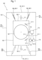
- Fig. 1 shows a schematic view of a general laundry care appliance 100, such as a washing machine or a clothes dryer.
- a schematic interior view of the laundry care device 100 is shown, the laundry care device 100 having a device housing 101 which delimits an interior space 103 of the laundry care device 100.
- the device housing 101 has a housing top 101-1, a housing bottom 101-2, a first housing longitudinal side 101-3 and a second housing longitudinal side 101-4 opposite the first housing longitudinal side 101-3.
- the laundry care appliance 100 has a tub 105 for holding washing liquid, which is arranged in the appliance interior 103 of the laundry care appliance 100.
- the laundry care device 100 also has a laundry drum 107 Receiving laundry which is arranged in the tub 105, with laundry picked up in the laundry drum 107 in the Fig. 1 is not shown.
- the laundry care appliance 100 in particular has a vibration system 109, in particular a spring-loaded vibration system 109, which is arranged in the appliance interior 103 of the laundry care appliance 100 and is connected to the appliance housing 101 and the tub 105, the vibration system 109 being formed, the tub 105 and to oscillate the laundry drum 107 arranged in the tub 105.
- a vibration system 109 in particular a spring-loaded vibration system 109, which is arranged in the appliance interior 103 of the laundry care appliance 100 and is connected to the appliance housing 101 and the tub 105, the vibration system 109 being formed, the tub 105 and to oscillate the laundry drum 107 arranged in the tub 105.
- the oscillation system 109 in particular the sprung oscillation system 109, has at least one upper spring 109-1, in particular two upper springs 109-1, and/or the oscillation system 109, in particular the sprung oscillation system 109, has at least one lower damper 109- 2, in particular two lower dampers 109-2.
- the at least one upper spring 109-1 is connected in particular to an upper tub area 105-1 of the tub 105 and/or the at least one lower damper 109-2 is connected in particular to a lower tub area 105-2 of the tub 105.
- the at least one upper spring 109-1 is connected in particular to the housing top 101-1 of the device housing 101 and/or the at least one lower damper 109-2 is connected in particular to the housing bottom 101-2 of the device housing 101.
- the at least one upper spring 109-1 can alternatively be connected in particular to the top of the housing 101-1, the first longitudinal side of the housing 101-3 and/or the second longitudinal side of the housing 101-4 of the device housing 101.
- the at least one lower damper 109-2 can alternatively be connected in particular to the underside of the housing 101-2, the first longitudinal side of the housing 101-3 and/or the second longitudinal side of the housing 101-4 of the device housing 101.
- the oscillating system 109 in particular the sprung oscillating system 109, ensures an advantageous oscillating mounting of the tub 105 and the laundry drum 107 accommodated in the tub 105.
- a vibration of the tub 105 and the laundry drum 107 accommodated in the tub 105 can be excited along a vertical direction 111, the vertical direction 111 extending between the top of the housing 101-1 and the bottom of the housing 101-2.
- the laundry care device 100 further has a drum drive 113 for rotating the laundry drum 107, the drum drive 113 being connected to the laundry drum 107 by a drive shaft 115, and the laundry drum 107 is designed in a first rotation direction 117-1 and in one of the first rotation direction 117 -1 to rotate in the opposite second rotation direction 117-2.
- the laundry care device 100 also has a control 119 for controlling the drum drive 113, the control 119 being connected to the drum drive 113 in particular by a first control connection 121-1.
- the laundry care device 100 in particular has a power detection element 123 for detecting a power value, in particular an electrical and/or mechanical power value, of the drum drive 113, the electrical power value in particular comprising a torque-forming current intensity of the drum drive 113, the mechanical power value in particular one caused by the drum drive 113
- Speed of the laundry drum 107 includes, which is connected to the drum drive 113 in particular by a second control connection 121-2.
- the power detection element 123 is further connected in particular to the controller 119 through a third control connection 121-3, the controller 119 being designed to evaluate the power value detected by the power detection element 123.
- Fig. 2 shows a schematic view of a laundry care device with a laundry drum and laundry sticking to the laundry drum.
- Fig. 1 For details With regard to the laundry care device 100, see the comments Fig. 1 referred.
- the laundry care device 100 has a device housing 101 delimiting the housing interior 103, a tub 105 for holding washing liquid and a laundry drum 107 arranged in the tub 105 for holding laundry 125.
- a drum drive 115 and a control 119 of the laundry care device 100 are in the Fig. 2 not shown.
- the laundry care device 100 also has a vibration system 109, in particular a spring-loaded vibration system 109, which is connected to the device housing 101 and the tub 105 and is designed to oscillate the tub 105 and the laundry drum 107 arranged in the tub 105.
- a vibration system 109 in particular a spring-loaded vibration system 109, which is connected to the device housing 101 and the tub 105 and is designed to oscillate the tub 105 and the laundry drum 107 arranged in the tub 105.
- the oscillation system 109 comprises at least one upper spring 109-1, in particular two upper springs 109-1, which is connected to the device housing 101, in particular one of the two upper springs 109-1 being connected to the first longitudinal side of the housing 101-3 and the other of the two upper springs 109-1 is connected to the second longitudinal side of the housing 101-4.
- one or both of the two upper springs 109-1 can also be connected to a housing top 101-1 of the device housing 101.
- the at least one upper spring 109-1 is connected to the tub 105, in particular to an upper tub area 105-1 of the tub 105.
- the oscillation system 109 comprises at least one lower damper 109-2, in particular two lower dampers 109-2, which is connected to the device housing 101, in particular one of the two lower dampers 109-2 being connected to the first longitudinal side of the housing 101-3 and the other of the two lower dampers 109-2 is connected to the second longitudinal side of the housing 101-4.
- One or both of the two lower dampers 109-2 can also be connected to a housing underside 101-2 of the device housing 101.
- the oscillating system 109 which is present in particular in the laundry care appliance 100, ensures an advantageous oscillating mounting of the tub 105 and the laundry drum 107 arranged in the tub 105.
- a non-rotating laundry drum 107 is shown after a spin cycle of the laundry care appliance 100.
- the laundry drum 107 is rotated at a high speed during the spinning process in order to expel washing liquid bound in the laundry 125.
- the laundry 125 picked up in the laundry drum 107 lies against the laundry drum 107 during the spinning process and forms an in Fig. 2 shown laundry ring, which adheres to the laundry drum 107 and often does not detach from the laundry drum 107 even after the spin cycle has ended.
- the laundry ring is formed due to the centrifugal force acting on the laundry 125 during the spinning process and is created by compacting the laundry 125, which increases the adhesion of the fibers of the laundry 125 to one another.
- the laundry drum 107 aligns itself due to the force of gravity acting on the unbalance 127 in such a way that a lower region 107-1 of the laundry drum 107 in which the unbalance 127 of the laundry 125 is arranged is on the underside of the housing 101- 1 is facing.
- the position of the laundry drum 107 shown can also be referred to as the 6 o'clock position and defines the rest position of the laundry drum 107 after the end of the spinning process.
- the occurrence of laundry 125 sticking to the laundry drum 107 after the spinning process can be disadvantageous, since the laundry 125 sticking to the laundry drum 107 often has to be laboriously removed from the laundry drum 107 by the user when it is removed from the laundry drum 107.
- the laundry care device 100 is designed as a tumble dryer, a further problem can arise from laundry 125 sticking to the laundry drum 107, since in a tumble dryer after the spin cycle a drying process is often carried out in which warm air from the laundry 125 picked up in the laundry drum 107 is supplied. Laundry 125 adhering to the laundry drum 107 can impair the supply of warm air into the laundry drum 107 or, if used improperly, may lead to damage to the laundry 125 adhering to the laundry drum 107.
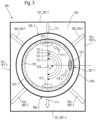
- Fig. 3 shows a schematic view of a laundry care device with a laundry drum and with laundry adhering to the laundry drum according to one embodiment.
- Laundry care device 100 shown according to the embodiment corresponds to that in the Fig. 2 Laundry care device 100 shown except that the laundry drum 107 is removed from the in Fig. 2 the rest position shown, especially the 6 o'clock position, in the in Fig. 3 Starting position shown, in particular the 3 o'clock position, was rotated.
- the laundry drum 107 was removed from the in Fig. 2 shown rest position, in a first rotation direction 117-1 by a starting angle 129 in the in Fig. 3 Start position shown rotates.
- Starting position shown is a lower area 107-1 of the laundry drum 107 in which the unbalance 127 of the laundry 125 is arranged, facing away from the underside of the housing 101-1.
- the lower region 107-1 of the laundry drum 107, in which the unbalance 127 of the laundry 125 is arranged faces the second longitudinal side of the housing 101-4.
- the starting position shown is not fixed to the 3 o'clock position, but can in particular be the 12 o'clock, 11 o'clock, 10 o'clock, 9 o'clock, 8 o'clock, 7 o'clock, 5 o'clock, 4 o'clock, 3 -Oclock, 2 o'clock or 1 o'clock position.
- Control 119 is designed to activate the drum drive 113 during a first rotation period of the laundry removal process following the positioning period in order to rotate the laundry drum 107 in a first rotation direction 117-1 by a first rotation angle 131-1 into a first rotation position.
- the first rotation angle 131-1 is in particular 90°.
- the first rotation angle 131-1 may comprise any angle in a range between 0° and 90°, in particular 30°, 60° or 90°, so that the first rotation position of the laundry drum 107 after the end of the first rotation period of the Laundry detachment process comes to a standstill in an area between the 3 o'clock position and the 12 o'clock position, in particular in the 2 o'clock position, 1 o'clock position, or 12 o'clock position.
- the controller 119 is further designed to activate the drum drive 113 during a second rotation period of the laundry removal process following the first rotation period in order to move the laundry drum 107 in a second rotation direction 117-2 opposite the first rotation direction 117-1 second rotation angle 131-2 to rotate into a second rotation position.
- the second rotation angle 131-2 is in particular 180°.
- the laundry drum 107 comes into the in Fig. 2 shown rest position, especially the 6 o'clock position, to a standstill.
- the second rotation angle 131-2 may comprise any angle in a range between 0° and 180°, in particular 30°, 60°, 90°, 120°, 150° or 180°, so that the second rotation position of the Laundry drum 107 comes to a standstill after the end of the second rotation period of the laundry removal process in an area between the 12 o'clock position and the 6 o'clock position, in particular in the 1 o'clock position, 2 o'clock position, 3 o'clock position position, 4 o'clock position, 5 o'clock position or 6 o'clock position.
- the controller 119 is designed to repeat the first and second rotation period of the laundry removal process several times in order to rotate the laundry drum 107 alternately in the first rotation direction 117-1 and in the second rotation direction 117-2 between the first and second rotation positions and on the laundry drum 107 to remove stuck laundry 125.
- the controller 119 is designed to activate the drum drive 115 during the repeated first rotation period following the second rotation period in order to move the laundry drum 107 from the second rotation position by a repeated first rotation angle 131-3 in the first rotation direction 117-1 to rotate the first rotation position, the repeated first rotation angle 131-3 being between 0° and 180°, in particular 180°.
- the controller 119 is designed to activate the drum drive 115 during the repeated second rotation period following the repeated first rotation period in order to move the laundry drum 107 from the first rotation position by a repeated second rotation angle 131-4 in the second rotation direction 117-2 to rotate the second rotation position, the repeated second rotation angle 131-4 being between 0° and 180°, in particular 180°.
- the controller 119 can in particular repeat the repeated first rotation period and the subsequent repeated second rotation period as often as desired.
- the laundry 125 adhering to the laundry drum 107 can be advantageously removed without the need for structural changes to the laundry care device 100.
- the controller 119 is designed in particular to stimulate a vibration of the tub 105, which is swingably mounted by the oscillation system 109, and the laundry drum 107 accommodated in the tub 105, along a vertical direction 111, through the alternating rotation of the laundry drum 107 during the first and second rotation periods, in order to work on the Laundry 125 adhering to the laundry drum 107 can be removed from the laundry drum 107.
- the vertical direction 111 extends between the device top 101-1 and the device bottom 101-2 of the device housing 101.
- the controller 119 is in particular designed to stimulate a periodic oscillation, in particular a sinusoidal oscillation, of the oscillatingly mounted tub 105 and the laundry drum 107 accommodated in the tub 105 along the vertical direction 111 by the alternating rotation of the laundry drum 107 in order to act on the laundry drum 107 to remove adhering laundry 125 from the laundry drum 107.
- the oscillation system 109 is in particular designed to oscillate at a natural oscillation frequency
- the controller 119 is in particular designed to activate the drum drive 113 to alternately rotate the laundry drum 107 during the first and second rotation time periods at a rotation frequency, the rotation frequency being the oscillation natural frequency of the Vibration system 109 corresponds.
- the controller 119 is designed to activate the drum drive 113 during a first inversion rotation period of the laundry detachment process after repeating the first and second rotation period of the laundry detachment process several times in order to move the laundry drum 107 in the second direction of rotation 117 -2 to rotate to an inverted first rotation position.
- the laundry drum 107 is rotated in the second rotation direction 117-2 during the first inversion rotation period opposite to the first rotation direction 117-1, so that the inverted first rotation position of the laundry drum 107 after the end of the second rotation period of the laundry detachment process is in a range between the 12th o'clock position and the 6 o'clock position comes to a stop, especially at the 11 o'clock position, 10 o'clock position, or 9 o'clock position.
- the controller 119 is further designed in particular to activate the drum drive 113 during a second inversion rotation period of the laundry removal process following the first inversion rotation period in order to move the laundry drum 107 from the inverted first rotation position into a first rotation direction 117-1 that is opposite to the inverted first rotation direction to rotate in the inverted second rotation position, so that the inverted second rotation position of the laundry drum 107 comes to a standstill in an area between the 12 o'clock position and the 6 o'clock position after the end of the inverted second rotation period of the laundry removal process, in particular in the 9 o'clock position. Clock position, 8 o'clock position, 7 o'clock position or 6 o'clock position.
- the controller 119 is designed to repeat the inverted first and second rotation period of the laundry removal process several times in order to Laundry drum 107 to rotate alternately in the second rotation direction 117-2 and in the first rotation direction 117-1 between the inverted second and first rotation positions and to detach laundry 125 adhering to the laundry drum 107 from the laundry drum 107.
- the laundry care device 100 has a power detection element 123 for detecting a power value, in particular torque-forming current, of the drum drive 113.
- the controller 119 is designed to activate the drum drive 113 during a detection process before the laundry removal process in order to rotate the laundry drum 107.
- the controller 119 is in particular designed to start the laundry removal process after the detection process if the electrical power value detected during the detection process exceeds a power threshold value.
- the controller 119 determines the presence by comparing the electrical power value with the power threshold value of a laundry ring.
- the controller 119 if the power threshold value is exceeded by the detected electrical power value, the presence of laundry 125 adhering to the laundry drum 107 can be detected by the controller 119.
- the controller 119 is in particular designed to activate the drum drive 113 during a further detection process after the second rotation period of the laundry removal process in order to rotate the laundry drum 107.
- the controller 119 is designed to repeat the first and second rotation period of the laundry removal process after the further detection process if the electrical power value detected during the further detection process exceeds a power threshold value.
- the controller 119 is designed to end the second rotation period of the laundry removal process when the electrical power value detected during the further detection process falls below the power threshold value.
- the laundry care device 100 has an output element, in particular a light element, for outputting an indication, in particular a warning light, to the user of the laundry care device 100.
- the controller 119 is in particular designed to activate the output element for issuing a message to the user of the laundry care device 100 if, after the further detection process, the electrical power value detected during the further detection process exceeds a power threshold value, so that the user is aware of the presence of a problem on the laundry drum 107 adherent laundry ring can be displayed.
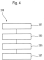
- Fig. 4 shows a schematic representation of a method for caring for laundry in a laundry care device.
- the method 200 includes, as a first method step, the activation 201 of the drum drive 123 by the controller 119 after a spinning process of the laundry care appliance 100 during a positioning period of a laundry removal process in order to rotate the laundry drum 107 into a starting position.
- the method 200 includes, as a second method step, the activation 203 of the drum drive 123 by the controller 119 after the positioning period during a first rotation period of the laundry removal process in order to rotate the laundry drum 107 in a first rotation direction 117-1 into a first rotation position.
- the method 200 includes, as a third method step, the activation 205 of the drum drive 123 by the controller 119 during a second rotation period following the first rotation period Laundry detachment process to rotate the laundry drum 107 from the first rotation position in a second rotation direction 117-2 opposite the first rotation direction 117-1 into a second rotation position.
- the method 200 includes the repeated repetition 207 of the first and second rotation time periods by the controller 119 in order to rotate the laundry drum 107 alternately in the first rotation direction 117-1 and in the second rotation direction 117-2 between the first and second rotation positions to remove laundry 125 adhering to the laundry drum 107 from the laundry drum 107.
Landscapes
- Engineering & Computer Science (AREA)
- Textile Engineering (AREA)
- Control Of Washing Machine And Dryer (AREA)
Description
- Die vorliegende Erfindung betrifft ein Wäschepflegegerät mit einer Steuerung.
- In einem herkömmlichen Wäschepflegegerät wird während eines Schleudervorgangs die Wäschetrommel mit einer hohen Drehzahl rotiert, wodurch die in der Wäschetrommel aufgenommene Wäsche durch die wirkende Zentrifugalkraft gegen die Wäschetrommel gedrückt wird, so dass die Wäsche nach dem Schleudervorgang unter Umständen an der Wäschetrommel anhaften kann und durch den Nutzer oftmals nur umständlich aus der Wäschetrommel entnommen werden kann.
- In der
DE 103 44 158 B3 ist ein Verfahren zum Waschen und/oder Trocknen von Wäsche in einer Waschmaschine oder insbesondere in einem Wäschetrockner offenbart, wobei bei Erkennung eines nicht abgelösten Wäscherings durch die Sensormittel Wasser in den Laugenbehälter eingeleitet wird. - In der
DE 102 41 682 A1 ist ein Verfahren zum Betreiben einer programmierbaren Waschmaschine offenbart, wobei das Ablösen des Wäscherings an der Trommelinnenwand kontrolliert wird. - Die Offenlegungsschrift
EP 2 496 745 A2 offenbart eine Waschmaschine mit einer Trommel zur Aufnahme von Wäsche, einem Trommelantrieb zum Drehen der Trommel und einer Steuerung zur Steuerung des Trommelantriebs, wobei die Steuerung zur Durchführung eines Prozesses ausgelegt ist, bei dem die Wäsche zunächst geschleudert und mit Wasser besprüht wird und anschließend ein Wäscheschwingvorgang durchgeführt wird, bei dem die Trommel mehrmals abwechselnd in einer ersten Drehrichtung und in einer zweiten Drehrichtung gedreht wird. - Es ist die der Erfindung zugrundeliegende Aufgabe, ein Wäschepflegegerät anzugeben, bei dem ein wirksames Ablösen von an einer Wäschetrommel haftender Wäsche sichergestellt wird.
- Diese Aufgabe wird durch die Gegenstände mit den Merkmalen nach den unabhängigen Ansprüchen gelöst. Vorteilhafte Ausführungsformen sind Gegenstand der abhängigen Ansprüche, der Beschreibung und der Zeichnungen.
- Gemäß einem ersten Aspekt wird die erfindungsgemäße Aufgabe durch ein Wäschepflegegerät gelöst, mit einer Wäschetrommel zur Aufnahme von Wäsche, einem Trommelantrieb zum Rotieren der Wäschetrommel, und einer Steuerung zum Steuern des Trommelantriebs, wobei die Steuerung ausgebildet ist, nach einem Schleudervorgang des Wäschepflegegeräts den Trommelantrieb während eines Positionierungszeitabschnitts eines Wäscheablösungsvorgangs zu aktivieren, um die Wäschetrommel in eine Startposition zu rotieren, wobei die Steuerung ausgebildet ist, nach dem Positionierungszeitabschnitt den Trommelantrieb während eines ersten Rotationszeitabschnitts des, Wäscheablösungsvorgangs zu aktivieren, um die Wäschetrommel in einer ersten Rotationsrichtung in eine erste Rotationsposition zu rotieren, wobei die Steuerung ausgebildet ist, den Trommelantrieb während eines sich an den ersten Rotationszeitabschnitt anschließenden zweiten Rotationszeitabschnitts des Wäscheablösungsvorgangs zu aktivieren, um die Wäschetrommel von der ersten Rotationsposition in einer der ersten Rotationsrichtung entgegengesetzten zweiten Rotationsrichtung in eine zweite Rotationsposition zu rotieren, wobei die Steuerung ausgebildet ist, den ersten und zweiten Rotationszeitabschnitt des Wäscheablösungsvorgangs mehrmals zu wiederholen, um die Wäschetrommel abwechselnd in der ersten Rotationsrichtung und in der zweiten Rotationsrichtung zwischen der ersten und zweiten Rotationsposition zu rotieren und an der Wäschetrommel haftende Wäsche von der Wäschetrommel abzulösen.
- Dadurch wird der technische Vorteil erreicht, dass durch die abwechselnde Rotation der Wäschetrommel zwischen der ersten und zweiten Rotationsposition an der Wäschetrommel nach dem Schleudervorgang haftende Wäsche wirksam von der Wäschetrommel abgelöst werden kann.
- Während des Schleudervorgangs wird durch die auf die Wäsche in der rotierenden Wäschetrommel wirkende Zentrifugalkraft die Wäsche an die Wäschetrommel gepresst und verdichtet, wodurch ein an der Wäschetrommel haftender Wäschering entsteht.
- Um die an der Wäschetrommel haftende Wäsche abzulösen, aktiviert die Steuerung nach dem Schleudervorgang während des Positionierungszeitabschnitts den Trommelantrieb, um die Wäschetrommel in die Startposition zu rotieren. Die Startposition kann insbesondere einer beliebigen Position der Rotation der Wäschetrommel entsprechen, insbesondere einer 12-Uhr-, 1-Uhr-, 2-Uhr-, 3-Uhr-, 4-Uhr-, 5-Uhr-, 6-Uhr-, 7-Uhr-, 8-Uhr-, 9-Uhr-, 10-Uhr-, oder 11-Uhr-Position der Wäschetrommel.
- Nach dem Positionierungszeitabschnitt aktiviert die Steuerung während des ersten Rotationszeitabschnitts den Trommelantrieb, um die Wäschetrommel in der ersten Rotationsrichtung zu rotieren, und aktiviert die Steuerung während des sich an den ersten Rotationszeitabschnitt anschließenden zweiten Rotationszeitabschnitts den Trommelantrieb, um die Wäschetrommel von der ersten Rotationsposition in der zweiten Rotationsrichtung in die zweite Rotationsposition zu rotieren.
- Insbesondere aktiviert die Steuerung während des ersten Rotationszeitabschnitts den Trommelantrieb, um die Wäschetrommel in der ersten Rotationsrichtung, um weniger als eine Umdrehung der Wäschetrommel, insbesondere um einen Winkel zwischen 0° und 360° zu rotieren.
- Insbesondere aktiviert die Steuerung während des zweiten Rotationszeitabschnitts den Trommelantrieb, um die Wäschetrommel in der zweiten Rotationsrichtung, um weniger als eine Umdrehung der Wäschetrommel, insbesondere um einen Winkel zwischen 0° und 360° zu rotieren.
- Insbesondere entspricht ein erster Rotationswinkel der Rotation der Wäschetrommel während des ersten Rotationszeitabschnitts einem zweiten Rotationswinkel der Rotation der Wäschetrommel während des zweiten Rotationszeitabschnitts.
- Die erste und/oder zweite Rotationsposition kann insbesondere einer beliebigen Position der Rotation der Wäschetrommel entsprechen, insbesondere einer 12-Uhr-, 1-Uhr-, 2-Uhr-, 3-Uhr-, 4-Uhr-, 5-Uhr-, 6-Uhr-, 7-Uhr-, 8-Uhr-, 9-Uhr-, 10-Uhr-, oder 11-Uhr-Position der Wäschetrommel.
- Gemäß einer vorteilhaften Ausführungsform erstreckt sich die erste Rotationsrichtung bezogen auf die Rotation der Wäschetrommel entgegen dem Uhrzeigersinn und erstreckt sich die zweite Rotationsrichtung bezogen auf die Rotation der Wäschetrommel im Uhrzeigersinn.
- Gemäß einer alternativen vorteilhaften Ausführungsform erstreckt sich die zweite Rotationsrichtung bezogen auf die Rotation der Wäschetrommel entgegen dem Uhrzeigersinn und erstreckt sich die erste Rotationsrichtung bezogen auf die Rotation der Wäschetrommel im Uhrzeigersinn.
- Die Steuerung ist hierbei ausgebildet, den ersten und zweiten Rotationszeitabschnitt des Wäscheablösungsvorgangs mehrmals zu wiederholen, so dass die Wäschetrommel abwechselnd zwischen der ersten und zweiten Rotationsposition hin und her rotiert werden kann. Durch die während des ersten und zweiten Rotationszeitabschnitts auf die Wäsche wirkenden Beschleunigungs- und Abbremskräfte kann an der Wäschetrommel haftende Wäsche wirksam abgelöst werden.
- Unter einem Wäschepflegegerät wird ein Gerät verstanden, welches zur Wäschepflege eingesetzt wird, wie z.B. eine Waschmaschine oder ein Wäschetrockner. Insbesondere wird unter solch einem Wäschepflegegerät ein Haushaltswäschepflegegerät verstanden. Also ein Wäschepflegegerät, welches im Rahmen der Haushaltsführung verwendet wird, und mit dem Wäsche in haushaltsüblichen Mengen behandelt wird.
- In einer vorteilhaften Ausführungsform des Wäschepflegegeräts weist das Wäschepflegegerät ein Gerätegehäuse mit einer Gehäuseunterseite auf, wobei die Wäschetrommel nach dem Schleudervorgang des Wäschepflegegeräts in einer Ruheposition angeordnet ist, wobei in der Ruheposition der Wäschetrommel ein unterer Bereich der Wäschetrommel der Gehäuseunterseite zugewandt ist, und ist die Steuerung ausgebildet, den Trommelantrieb während des Positionierungszeitabschnitts zu aktivieren, um die Wäschetrommel von der Ruheposition in die Startposition zu rotieren, wobei in der Startposition der Wäschetrommel der untere Bereich der Wäschetrommel der Gehäuseunterseite abgewandt ist.
- Dadurch wird der technische Vorteil erreicht, dass eine vorteilhafte Startposition der Wäschetrommel für den Wäscheablösungsvorgang bereitgestellt werden kann, von der aus der Wäscheablösungsvorgang vorteilhaft gestartet werden kann.
- Nach dem Schleudervorgang verbleibt die Wäschetrommel bei deaktiviertem Trommelantrieb in der Ruheposition. Da sich während des Schleudervorgangs die Wäsche nicht gleichmäßig an die Wäschetrommel anhaftet, entsteht eine Unwucht in der an der Wäschetrommel anhaftenden Wäsche, wobei die Unwucht der Wäsche durch eine erhöhte Anzahl an Wäschestücken in einem Bereich des an der Wäschetrommel haftenden Wäscherings gebildet wird. Aufgrund der auf die Unwucht wirkenden Schwerkraft richtet sich nach dem Schleudervorgang bei deaktiviertem Trommelantrieb die Wäschetrommel so aus, dass in der Ruheposition der Wäschetrommel der untere Bereich der Wäschetrommel der Gehäuseunterseite des Gerätegehäuses zugewandt ist, so dass sich die Wäschetrommel in der Ruheposition insbesondere in der 6-Uhr-Position befindet.
- Wenn die Wäschetrommel während des Positionierungszeitabschnitts von der Ruheposition in die Startposition rotiert wird, ist der untere Bereich der Wäschetrommel der Gehäuseunterseite abgewandt. Somit befindet sich die Wäschetrommel in der Startposition insbesondere in der 12-Uhr-, 1-Uhr-, 2-Uhr-, 3-Uhr-, 4-Uhr-, 5-Uhr-, 7-Uhr-, 8-Uhr-, 9-Uhr-, 10-Uhr-, oder 11-Uhr-Position, insbesondere in der 3-Uhr- oder 9-Uhr-Position.
- In einer vorteilhaften Ausführungsform des Wäschepflegegeräts ist die Steuerung ausgebildet, den Trommelantrieb während des Positionierungszeitabschnitts zu aktivieren, um die Wäschetrommel von der Ruheposition in der ersten oder zweiten Rotationsrichtung um einen Startwinkel in die Startposition zu rotieren, wobei der Startwinkel zwischen 0° und 180°, insbesondere 90°, beträgt.
- Dadurch wird der technische Vorteil erreicht, dass die Startposition einen besonders vorteilhaften Ausgangspunkt für den Wäscheablösungsvorgang ermöglicht, um den Wäschering besonders vorteilhaft von der Wäschetrommel abzulösen. Hierbei kann die Wäschetrommel während des Positionierungszeitabschnitts insbesondere mit dem Uhrzeigersinn um den Startwinkel in die Startposition, insbesondere die 9-Uhr-Position der Wäschetrommel, rotiert werden oder kann die Wäschetrommel während des Positionierungszeitabschnitts insbesondere gegen den Uhrzeigersinn um den Startwinkel in die Startposition, insbesondere die 3-Uhr-Position der Wäschetrommel, rotiert werden.
- In einer vorteilhaften Ausführungsform des Wäschepflegegeräts ist die Steuerung ausgebildet, den Trommelantrieb während des ersten Rotationszeitabschnitts zu aktivieren, um die Wäschetrommel in der ersten Rotationsrichtung um einen ersten Rotationswinkel in die erste Rotationsposition zu rotieren, wobei der erste Rotationswinkel zwischen 0° und 180°, insbesondere 60°, beträgt, und/oder ist die Steuerung ausgebildet, den Trommelantrieb während des zweiten Rotationszeitabschnitts zu aktivieren, um die Wäschetrommel in der zweiten Rotationsrichtung um einen zweiten Rotationswinkel in die zweite Rotationsposition zu rotieren, wobei der zweite Rotationswinkel zwischen 0° und 180°, insbesondere 120°, beträgt.
- Dadurch wird der technische Vorteil erreicht, dass durch die Wahl eines geeigneten ersten und/oder zweiten Rotationswinkels die erste und/oder zweite Rotationsposition derart eingestellt werden kann, um eine besonders wirksame Ablösung der an der Wäschetrommel haftenden Wäsche sicherzustellen.
- Insbesondere wird während des ersten Rotationszeitabschnitts die Wäschetrommel von der Startposition, insbesondere der 3-Uhr-Position oder der 9-Uhr Position der Wäschetrommel, aus in der ersten Rotationsrichtung um einen ersten Rotationswinkel von insbesondere 60° in die erste Rotationsposition rotiert, wobei die erste Rotationsposition insbesondere der 1-Uhr-Position oder der 11 Uhr-Position der Wäschetrommel entspricht.
- Insbesondere wird während des zweiten Rotationszeitabschnitts die Wäschetrommel von der ersten Rotationsposition, insbesondere der 1-Uhr-Position oder der 11-Uhr-Position der Wäschetrommel, aus in der zweiten Rotationsrichtung um einen zweiten Rotationswinkel von insbesondere 120° in die zweite Rotationsposition rotiert, wobei die zweite Rotationsposition insbesondere der 5-Uhr-Position oder der 7-Uhr-Position der Wäschetrommel entspricht. Somit kann die Wäschetrommel insbesondere zwischen der 1-Uhr-Position und der 5-Uhr-Position hin und her bewegt werden oder kann die Wäschetrommel insbesondere zwischen der 11-Uhr-Position und der 7-Uhr-Position hin und her bewegt werden.
- In einer vorteilhaften Ausführungsform des Wäschepflegegeräts ist die Steuerung ausgebildet, den Trommelantrieb während des sich an den zweiten Rotationszeitabschnitt anschließenden wiederholten ersten Rotationszeitabschnitts zu aktivieren, um die Wäschetrommel von der zweiten Rotationsposition um einen wiederholten ersten Rotationswinkel in der ersten Rotationsrichtung in die erste Rotationsposition zu rotieren, wobei der wiederholte erste Rotationswinkel zwischen 0° und 180°, insbesondere 120°, beträgt.
- Dadurch wird der technische Vorteil erreicht, dass eine vorteilhafte Wiederholung des ersten Rotationszeitabschnitts sichergestellt werden kann.
- Insbesondere wird während des wiederholten ersten Rotationszeitabschnitts die Wäschetrommel von der zweiten Rotationsposition, insbesondere der 5-Uhr-Position oder 7-Uhr-Position der Wäschetrommel, aus in der ersten Rotationsrichtung um einen wiederholten ersten Rotationswinkel von 120° erneut in die erste Rotationsposition rotiert, wobei die erste Rotationsposition insbesondere der 1-Uhr-Position oder der 11-Uhr-Position der Wäschetrommel entspricht.
- In einer vorteilhaften Ausführungsform des Wäschepflegegeräts ist die Steuerung ausgebildet, den Trommelantrieb während des sich an den wiederholten ersten Rotationszeitabschnitt anschließenden wiederholten zweiten Rotationszeitabschnitts zu aktivieren, um die Wäschetrommel von der ersten Rotationsposition um einen wiederholten zweiten Rotationswinkel in der zweiten Rotationsrichtung in die zweite Rotationsposition zu rotieren, wobei der wiederholte zweite Rotationswinkel zwischen 0° und 180°, insbesondere 120°, beträgt.
- Dadurch wird der technische Vorteil erreicht, dass eine vorteilhafte Wiederholung des zweiten Rotationszeitabschnitts sichergestellt werden kann.
- Insbesondere wird während des wiederholten zweiten Rotationszeitabschnitts die Wäschetrommel von der ersten Rotationsposition, insbesondere der 1-Uhr-Position oder der 11-Uhr-Position der Wäschetrommel, aus in der zweiten Rotationsrichtung um einen wiederholten zweiten Rotationswinkel von 120° erneut in die zweite Rotationsposition rotiert, wobei die zweite Rotationsposition insbesondere der 5-Uhr-Position oder der 7-Uhr-Position der Wäschetrommel entspricht.
- Die Rotation der Wäschetrommel zwischen der ersten und zweiten Rotationsposition kann durch die Steuerung beliebig oft wiederholt werden, so dass die Wäschetrommel insbesondere zwischen der 1-Uhr- und der 5-Uhr-Position, bzw. der 11-Uhr- und der 7-Uhr-Position hin und her rotiert werden kann.
- In einer vorteilhaften Ausführungsform des Wäschepflegegeräts weist das Wäschepflegegerät einen Laugenbehälter zur Aufnahme von Waschflüssigkeit auf, wobei die Wäschetrommel in dem Laugenbehälter rotierbar gelagert ist, weist das Wäschepflegegerät ein Schwingsystem, insbesondere ein gefedertes Schwingsystem, auf, welches mit einem Gerätegehäuse des Wäschepflegegeräts und mit dem Laugenbehälter verbunden ist, um den Laugenbehälter und die in dem Laugenbehälter aufgenommene Wäschetrommel schwingbar zu lagern, wobei die Steuerung ausgebildet ist, durch die abwechselnde Rotation der Wäschetrommel während der ersten und zweiten Rotationszeitabschnitte eine Schwingung des Laugenbehälters und der in dem Laugenbehälter aufgenommenen Wäschetrommel entlang einer Vertikalrichtung anzuregen, um an der Wäschetrommel haftende Wäsche von der Wäschetrommel abzulösen, wobei sich die Vertikalrichtung zwischen einer Gehäuseoberseite und einer Gehäuseunterseite des Gerätegehäuses erstreckt.
- Dadurch wird der technische Vorteil erreicht, dass das Schwingsystem eine vorteilhafte Schwingung des Laugenbehälters und der in dem Laugenbehälter aufgenommenen Wäschetrommel entlang der Vertikalrichtung zulässt. Durch das Anregen der Schwingung der Wäschetrommel durch die sich wiederholende abwechselnde Rotation der Wäschetrommel in der ersten und zweiten Rotationsrichtung kann ein besonders vorteilhaftes Ablösen der an der Wäschetrommel haftenden Wäsche sichergestellt werden.
- In einer vorteilhaften Ausführungsform des Wäschepflegegeräts ist die Steuerung ausgebildet, den Trommelantrieb zu aktivieren, um durch die abwechselnde Rotation der Wäschetrommel in der ersten und zweiten Rotationsrichtung eine periodische Schwingung, insbesondere eine sinus-förmige Schwingung, der in dem Laugenbehälter aufgenommenen Wäschetrommel entlang der Vertikalrichtung anzuregen, um an der Wäschetrommel haftende Wäsche von der Wäschetrommel abzulösen.
- Dadurch wird der technische Vorteil erreicht, dass ein besonders vorteilhaftes Ablösen der an der Wäschetrommel anhaftenden Wäsche sichergestellt werden kann.
- In einer vorteilhaften Ausführungsform des Wäschepflegegeräts ist das Schwingsystem ausgebildet, mit einer Schwingungseigenfrequenz zu schwingen, und ist die Steuerung ausgebildet, den Trommelantrieb zu aktivieren, um die Wäschetrommel abwechselnd in der ersten und zweiten Rotationsrichtung mit einer Rotationsfrequenz zu rotieren, wobei die Rotationsfrequenz der Schwingungseigenfrequenz des Schwingsystems entspricht.
- Dadurch wird der technische Vorteil erreicht, dass die Steuerung während der ersten und zweiten Rotationszeitabschnitte die Wäschetrommel mit einer Rotationsfrequenz zwischen der ersten und zweiten Rotationsposition hin und her rotiert. Dadurch, dass die Rotationsfrequenz der rotierenden Wäschetrommel der Schwingungseigenfrequenz des Schwingsystems entspricht, kann eine besonders vorteilhafte Schwingung des Schwingsystems angeregt, insbesondere resonant verstärkt, werden, welche ein vorteilhaftes Ablösen der Wäsche von der Wäschetrommel ermöglicht.
- In einer vorteilhaften Ausführungsform des Wäschepflegegeräts weist das Schwingsystem zumindest eine obere Feder, insbesondere zwei obere Federn, auf, welche mit dem Gerätegehäuse und dem Laugenbehälter verbunden ist, und/oder weist das Schwingsystem zumindest einen unteren Dämpfer, insbesondere zwei untere Dämpfer, auf, welcher mit dem Gerätegehäuse und dem Laugenbehälter verbunden ist.
- Dadurch wird der technische Vorteil erreicht, dass die zumindest eine obere Feder und der zumindest eine untere Dämpfer eine vorteilhafte Schwingung des Schwingsystems sicherstellen können.
- In einer vorteilhaften Ausführungsform des Wäschepflegegeräts ist die zumindest eine obere Feder mit einer Gehäuseoberseite und/oder einer Gehäuselängsseite des Gerätegehäuses und mit einem oberen Laugenbehälterbereich des Laugenbehälters verbunden, und/oder ist der zumindest eine untere Dämpfer mit einer Gehäuseunterseite und/oder einer Gehäuselängsseite des Gerätegehäuses und mit einem unteren Laugenbehälterbereich des Laugenbehälters verbunden.
- Dadurch wird der technische Vorteil erreicht, dass eine wirksame Befestigung des Schwingsystems sichergestellt wird.
- In einer vorteilhaften Ausführungsform des Wäschepflegegeräts weist das Wäschepflegegerät ein Leistungserfassungselement zum Erfassen eines Leistungswerts, insbesondere elektrischen und/oder mechanischen Leistungswert des Trommelantriebs auf, wobei der elektrische Leistungswert insbesondere eine drehmomentbildende Stromstärke des Trommelantriebs umfasst, wobei der mechanische Leistungswert insbesondere eine durch den Trommelantrieb bewirkte Drehzahl der Wäschetrommel umfasst, ist die Steuerung ausgebildet, vor dem Wäscheablösungsvorgang während eines Erfassungsvorgangs zum Erfassen einer Unwucht in der Wäschetrommel den Trommelantrieb zu aktivieren, um die Wäschetrommel zu rotieren, wobei die Steuerung ausgebildet ist, nach dem Erfassungsvorgang den Wäscheablösungsvorgang zu beginnen, wenn der während des Erfassungsvorgangs erfasste Leistungswert einen Leistungsschwellenwert überschreitet, und/oder ist die Steuerung ausgebildet, während des sich an den Erfassungsvorgang anschließenden Wäscheablösungsvorgangs die Startposition der Wäschetrommel in Abhängigkeit von dem erfassten Leistungswert zu bestimmen.
- Dadurch wird der technische Vorteil erreicht, dass die Steuerung durch einen Vergleich des Leistungswerts mit dem Leistungsschwellenwert das Vorliegen eines Wäscherings anhand einer Unwucht in der Wäschetrommel erfassen kann. In Abhängigkeit davon ob die Wäsche an der Wäschetrommel anliegt oder nicht, unterscheidet sich der Leistungswert, den der Trommelantrieb benötigt, um die Wäschetrommel aus dem Stillstand heraus zu rotieren, so dass das Vorliegen eines Wäscherings wirksam erfasst werden kann. Wird das Vorliegen eines Wäscherings erfasst, beginnt die Steuerung den Wäscheablösungsvorgang. Alternativ oder zusätzlich kann die Steuerung in Abhängigkeit des erfassten Leistungswertes die Startposition der Wäschetrommel während des sich anschließenden Wäscheablösungsvorgang bestimmen
- Insbesondere kann die Steuerung eine durch ein mechanisches Leistungserfassungselement erfasste Drehzahl der Wäschetrommel auswerten und bei einem Minimum der erfassten Drehzahl die Ruheposition der Wäschetrommel erfassen, wobei die Steuerung insbesondere ausgebildet ist, die Startposition der Wäschetrommel in Abhängigkeit von der erfassten Ruheposition zu bestimmen.
- Insbesondere kann die Steuerung einen durch ein elektrisches Leistungserfassungselement erfassten Drehmoment-bildenden Strom des Trommelantriebs auswerten und bei einem Maximum des erfassten Drehmoment-bildenden Stroms eine Position der Wäschetrommel erfassen.
- In einer vorteilhaften Ausführungsform des Wäschepflegegeräts weist das Wäschepflegegerät ein Leistungserfassungselement zum Erfassen eines Leistungswerts, insbesondere elektrischen und/oder mechanischen Leistungswert des Trommelantriebs auf, wobei der elektrische Leistungswert insbesondere eine drehmomentbildende Stromstärke des Trommelantriebs umfasst, wobei der mechanische Leistungswert insbesondere eine durch den Trommelantrieb bewirkte Drehzahl der Wäschetrommel umfasst, ist die Steuerung ausgebildet, nach dem zweiten Rotationszeitabschnitt des Wäscheablösungsvorgangs während eines weiteren Erfassungsvorgangs zum Erfassen einer Unwucht in der Wäschetrommel den Trommelantrieb zu aktivieren, um die Wäschetrommel zu rotieren, wobei die Steuerung ausgebildet ist, nach dem weiteren Erfassungsvorgang den ersten und zweiten Rotationszeitabschnitt des Wäscheablösungsvorgangs zu wiederholen, wenn der während des weiteren Erfassungsvorgangs erfasste Leistungswert einen Leistungsschwellenwert überschreitet.
- Dadurch wird der technische Vorteil erreicht, dass in Abhängigkeit davon ob die Wäsche an der Wäschetrommel anliegt oder nicht, sich der Leistungswert, den der Trommelantrieb benötigt, um die Wäschetrommel aus dem Stillstand heraus zu rotieren unterscheidet, so dass das Vorliegen eines Wäscherings mittels einer erfassten Unwucht der Wäschetrommel wirksam erfasst werden kann. Wird erfasst, dass nach dem zweiten Rotationszeitabschnitt immer noch Wäsche an der Wäschetrommel anhaftet, wiederholt die Steuerung den ersten und zweiten Rotationszeitabschnitt, insbesondere solange bis kein Wäschering mehr erfasst werden kann.
- In einer vorteilhaften Ausführungsform des Wäschepflegegeräts weist das Wäschepflegegerät ein Ausgabeelement zum Ausgeben eines Hinweises an den Nutzer des Wäschepflegegeräts auf, wobei die Steuerung ausgebildet ist, das Ausgabeelement zum Ausgeben eines Hinweises an den Nutzer des Wäschepflegegeräts zu aktivieren, wenn nach dem weiteren Erfassungsvorgang der während des weiteren Erfassungsvorgangs erfasste Leistungswert den Leistungsschwellenwert überschreitet.
- Dadurch wird der technische Vorteil erreicht, dass dem Nutzer des Wäschepflegegeräts angezeigt werden kann, dass sich der Wäschering nach dem weiteren Erfassungsvorgang noch nicht von der Wäschetrommel gelöst hat.
- In einer vorteilhaften Ausführungsform des Wäschepflegegeräts weist das Wäschepflegegerät einen Positionssensor, insbesondere magnetischen Sensor, optischen Sensor und/oder Beschleunigungssensor, auf, welcher ausgebildet ist, eine Rotationsposition der Wäschetrommel, insbesondere die Startposition, die erste Rotationsposition, die zweite Rotationsposition und/oder die Ruheposition der Wäschetrommel, zu erfassen.
- Dadurch wird der technische Vorteil erreicht, dass durch den Positionssensor, insbesondere externen Positionssensor, vorteilhaft die Rotationspositionen der Wäschetrommel durch die Steuerung bestimmt werden können. In Abhängigkeit der bestimmten Rotationsposition der Wäschetrommel ist die Steuerung insbesondere ausgebildet, den jeweiligen Rotationswinkel während des jeweiligen Rotationszeitabschnitts zu bestimmen.
- Gemäß einem zweiten Aspekt wird die erfindungsgemäße Aufgabe durch ein Verfahren zum Pflegen von Wäsche in einem Wäschepflegegerät gelöst, wobei das Wäschepflegegerät eine Wäschetrommel zur Aufnahme von Wäsche, einen Trommelantrieb zum Rotieren der Wäschetrommel, und eine Steuerung zum Steuern des Trommelantriebs aufweist, wobei das Verfahren die folgenden Verfahrensschritte aufweist, Aktivieren des Trommelantriebs durch die Steuerung nach einem Schleudervorgang des Wäschepflegegeräts während eines Positionierungszeitabschnitts eines Wäscheablösungsvorgangs, um die Wäschetrommel in eine Startposition zu rotieren, Aktivieren des Trommelantriebs durch die Steuerung nach dem Positionierungszeitabschnitt während eines ersten Rotationszeitabschnitts des Wäscheablösungsvorgangs, um die Wäschetrommel in einer ersten Rotationsrichtung in eine erste Rotationsposition zu rotieren, Aktivieren des Trommelantriebs durch die Steuerung während eines sich an den ersten Rotationszeitabschnitt anschließenden zweiten Rotationszeitabschnitts des Wäscheablösungsvorgangs, um die Wäschetrommel von der ersten Rotationsposition in einer der ersten Rotationsrichtung entgegengesetzten zweiten Rotationsrichtung in eine zweite Rotationsposition zu rotieren, Mehrmaliges Wiederholen des ersten und zweiten Rotationszeitabschnitts durch die Steuerung, um die Wäschetrommel abwechselnd in der ersten Rotationsrichtung und in der zweiten Rotationsrichtung zwischen der ersten und zweiten Rotationsposition zu rotieren und an der Wäschetrommel haftende Wäsche von der Wäschetrommel abzulösen.
- Dadurch wird der technische Vorteil erreicht, dass ein wirksames Ablösen von an der Wäschetrommel haftender Wäsche sichergestellt werden kann.
- Ausführungsbeispiele der Erfindung sind in den Zeichnungen dargestellt und werden im Folgenden näher beschrieben.
- Es zeigen:
- Fig. 1
- eine schematische Ansicht eines Wäschepflegegeräts;
- Fig. 2
- eine schematische Ansicht eines Wäschepflegegeräts mit einer Wäschetrommel und mit an der Wäschetrommel haftender Wäsche;
- Fig. 3
- eine schematische Ansicht eines Wäschepflegegeräts mit einer Wäschetrommel und mit an der Wäschetrommel haftender Wäsche gemäß einer Ausführungsform; und
- Fig. 4
- eine schematische Darstellung eines Verfahrens zum Pflegen von Wäsche in einem Wäschepflegegerät.
-
Fig. 1 zeigt eine schematische Ansicht eines allgemeinen Wäschepflegegeräts 100, wie z.B. eine Waschmaschine oder einen Wäschetrockner. InFig. 1 ist eine schematische Innenansicht des Wäschepflegegeräts 100 gezeigt, wobei das Wäschepflegegerät 100 ein Gerätegehäuse 101 aufweist, welches einen Geräteinnenraum 103 des Wäschepflegegeräts 100 begrenzt. Das Gerätegehäuse 101 weist eine Gehäuseoberseite 101-1, eine Gehäuseunterseite 101-2, eine erste Gehäuselängsseite 101-3 und eine der ersten Gehäuselängsseite 101-3 gegenüberliegende zweite Gehäuselängsseite 101-4 auf. - Das Wäschepflegegerät 100 weist einen Laugenbehälter 105 zur Aufnahme von Waschflüssigkeit auf, welcher in dem Geräteinnenraum 103 des Wäschepflegegeräts 100 angeordnet ist. Das Wäschepflegegerät 100 weist ferner eine Wäschetrommel 107 zur Aufnahme von Wäsche auf, welche in dem Laugenbehälter 105 angeordnet ist, wobei in der Wäschetrommel 107 aufgenommene Wäsche in der
Fig. 1 nicht dargestellt ist. - Hierbei weist das Wäschepflegegerät 100 insbesondere ein Schwingsystem 109, insbesondere ein gefedertes Schwingsystem 109, auf, welches in dem Geräteinnenraum 103 des Wäschepflegegeräts 100 angeordnet und mit dem Gerätegehäuse 101 und dem Laugenbehälter 105 verbunden ist, wobei das Schwingsystem 109 ausgebildet ist, den Laugenbehälter 105 und die in dem Laugenbehälter 105 angeordnete Wäschetrommel 107 schwingbar zu lagern.
- Hierbei weist das Schwingsystem 109, insbesondere das gefedertes Schwingsystem 109, zumindest eine obere Feder 109-1, insbesondere zwei obere Federn 109-1, auf, und/oder weist das Schwingsystem 109, insbesondere das gefedertes Schwingsystem 109, zumindest einen unteren Dämpfer 109-2, insbesondere zwei untere Dämpfer 109-2, auf.
- Wie aus der
Fig. 1 zu entnehmen ist, ist die zumindest eine obere Feder 109-1 insbesondere mit einem oberen Laugenbehälterbereich 105-1 des Laugenbehälters 105 verbunden und/oder ist der zumindest eine untere Dämpfer 109-2 insbesondere mit einem unteren Laugenbehälterbereich 105-2 des Laugenbehälters 105 verbunden. - Wie aus der
Fig. 1 zu entnehmen ist, ist die zumindest eine obere Feder 109-1 insbesondere mit der Gehäuseoberseite 101-1 des Gerätegehäuses 101 verbunden und/oder ist der zumindest eine untere Dämpfer 109-2 insbesondere mit der Gehäuseunterseite 101-2 des Gerätegehäuses 101 verbunden. - Auch wenn dies in
Fig. 1 nicht dargestellt ist, kann alternativ die zumindest eine obere Feder 109-1 insbesondere mit der Gehäuseoberseite 101-1, der ersten Gehäuselängsseite 101-3 und/oder der zweiten Gehäuselängsseite 101-4 des Gerätegehäuses 101 verbunden sein. Auch wenn dies inFig. 1 nicht dargestellt ist, kann alternativ der zumindest eine untere Dämpfer 109-2 insbesondere mit der Gehäuseunterseite 101-2, der ersten Gehäuselängsseite 101-3 und/oder der zweiten Gehäuselängsseite 101-4 des Gerätegehäuses 101 verbunden sein. - Durch das Schwingsystem 109, insbesondere das gefederte Schwingsystem 109, wird eine vorteilhafte schwingbare Lagerung des Laugenbehälters 105 und der in dem Laugenbehälter 105 aufgenommenen Wäschetrommel 107 sichergestellt.
- Hierbei kann insbesondere eine Schwingung des Laugenbehälters 105 und der in dem Laugenbehälter 105 aufgenommenen Wäschetrommel 107 entlang einer Vertikalrichtung 111 angeregt werden, wobei sich die Vertikalrichtung 111 zwischen der Gehäuseoberseite 101-1 und der Gehäuseunterseite 101-2 erstreckt.
- Das Wäschepflegegerät 100 weist ferner einen Trommelantrieb 113 zum Rotieren der Wäschetrommel 107 auf, wobei der Trommelantrieb 113 durch eine Antriebswelle 115 mit der Wäschetrommel 107 verbunden ist, und ausgebildet ist die Wäschetrommel 107 in einer ersten Rotationsrichtung 117-1 und in einer der ersten Rotationsrichtung 117-1 entgegengesetzten zweiten Rotationsrichtung 117-2 zu rotieren.
- Das Wäschepflegegerät 100 weist ferner eine Steuerung 119 zum Steuern des Trommelantriebs 113 auf, wobei die Steuerung 119 mit dem Trommelantrieb 113 insbesondere durch eine erste Steuerungsverbindung 121-1 verbunden ist.
- Das Wäschepflegegerät 100 weist insbesondere ein Leistungserfassungselement 123 zum Erfassen eines Leistungswerts, insbesondere elektrischen und/oder mechanischen Leistungswert, des Trommelantriebs 113 auf, wobei der elektrische Leistungswert insbesondere eine drehmomentbildende Stromstärke des Trommelantriebs 113 umfasst, wobei der mechanische Leistungswert insbesondere eine durch den Trommelantrieb 113 bewirkte Drehzahl der Wäschetrommel 107 umfasst, welches mit dem Trommelantrieb 113 insbesondere durch eine zweite Steuerungsverbindung 121-2 verbunden ist.
- Das Leistungserfassungselement 123 ist ferner insbesondere mit der Steuerung 119 durch eine dritte Steuerungsverbindung 121-3 verbunden, wobei die Steuerung 119 ausgebildet ist, den durch das Leistungserfassungselement 123 erfassten Leistungswert auszuwerten.
-
Fig. 2 zeigt eine schematische Ansicht eines Wäschepflegegeräts mit einer Wäschetrommel und mit an der Wäschetrommel haftender Wäsche. Für Details hinsichtlich des Wäschepflegegeräts 100 wird auf die Ausführungen zu derFig. 1 verwiesen. - Das Wäschepflegegerät 100 weist ein den Gehäuseinnenraum 103 begrenzendes Gerätegehäuse 101, einen Laugenbehälter 105 zur Aufnahme von Waschflüssigkeit und eine in dem Laugenbehälter 105 angeordnete Wäschetrommel 107 zur Aufnahme von Wäsche 125 auf.
- Ein Trommelantrieb 115 und eine Steuerung 119 des Wäschepflegegeräts 100 sind in der
Fig. 2 nicht dargestellt. - Hierbei weist das Wäschepflegegerät 100 ferner ein Schwingsystem 109, insbesondere ein gefedertes Schwingsystem 109, auf, welches mit dem Gerätegehäuse 101 und dem Laugenbehälter 105 verbunden und ausgebildet ist den Laugenbehälter 105 und die in dem Laugenbehälter 105 angeordnete Wäschetrommel 107 schwingbar zu lagern.
- Wie in der
Fig. 2 zu erkennen ist, umfasst das Schwingsystem 109 zumindest eine obere Feder 109-1, insbesondere zwei obere Federn 109-1, welche mit dem Gerätegehäuse 101 verbunden ist, wobei insbesondere eine der beiden oberen Federn 109-1 mit der ersten Gehäuselängsseite 101-3 und die andere der beiden oberen Federn 109-1 mit der zweiten Gehäuselängsseite 101-4 verbunden ist. Alternativ kann auch eine oder beide der beiden oberen Federn 109-1 mit einer Gehäuseoberseite 101-1 des Gerätegehäuses 101 verbunden sein. - Hierbei ist die zumindest eine obere Feder 109-1 mit dem Laugenbehälter 105, insbesondere mit einem oberen Laugenbehälterbereich 105-1 des Laugenbehälters 105 verbunden.
- Wie in der
Fig. 2 zu erkennen ist, umfasst das Schwingsystem 109 zumindest einen unteren Dämpfer 109-2, insbesondere zwei untere Dämpfer 109-2, welcher mit dem Gerätegehäuse 101 verbunden ist, wobei insbesondere eine der beiden unteren Dämpfer 109-2 mit der ersten Gehäuselängsseite 101-3 und der andere der beiden unteren Dämpfer 109-2 mit der zweiten Gehäuselängsseite 101-4 verbunden ist. Alternativ kann auch eine oder beide der beiden unteren Dämpfer 109-2 mit einer Gehäuseunterseite 101-2 des Gerätegehäuses 101 verbunden sein. - Durch das insbesondere in dem Wäschepflegegerät 100 vorhandene Schwingsystem 109, wird eine vorteilhafte schwingbare Lagerung des Laugenbehälters 105 und der in dem Laugenbehälter 105 angeordneten Wäschetrommel 107 sichergestellt.
- In der
Fig. 2 ist eine nicht rotierende Wäschetrommel 107 nach einem Schleudervorgang des Wäschepflegegeräts 100 dargestellt. Zum Ende eines Wäschepflegevorgangs des Wäschepflegegeräts 100 wird die Wäschetrommel 107 während des Schleudervorgangs mit einer hohen Drehzahl rotiert, um in der Wäsche 125 gebundene Waschflüssigkeit auszutreiben. - Aufgrund der hohen Drehzahl der rotierenden Wäschetrommel 107 legt sich die in der Wäschetrommel 107 aufgenommene Wäsche 125 während des Schleudervorgangs hierbei an die Wäschetrommel 107 an und bildet einen in
Fig. 2 dargestellten Wäschering, welche an der Wäschetrommel 107 anhaftet und sich auch nach dem Ende des Schleudervorgangs oftmals nicht von der Wäschetrommel 107 löst. - Der Wäschering bildet sich hierbei aufgrund der auf die Wäsche 125 während des Schleudervorgangs wirkenden Zentrifugalkraft und entsteht durch ein Verdichten der Wäsche 125, wodurch die Haftung der Fasern der Wäsche 125 untereinander verstärkt wird.
- Da sich die Wäsche 125 während des Schleudervorgangs nicht vollständig gleichmäßig an die Wäschetrommel 107 anlegt, entsteht eine Unwucht 127 in der an der Wäschetrommel 107 anliegenden Wäsche 125, wobei die Unwucht 127 der Wäsche 125 durch eine erhöhte Anzahl an Wäschestücken in einem Bereich des an der Wäschetrommel 107 haftenden Wäscherings gebildet wird.
- Bei einem deaktivierten Trommelantrieb nach dem Ende des Schleudervorgangs richtet sich die Wäschetrommel 107 aufgrund der auf die Unwucht 127 wirkenden Schwerkraft so aus, dass ein unterer Bereich 107-1 der Wäschetrommel 107 in welchem die Unwucht 127 der Wäsche 125 angeordnet ist, der Gehäuseunterseite 101-1 zugewandt ist.
- Diese in
Fig. 2 dargestellte Position der Wäschetrommel 107 kann auch als 6-Uhr-Position bezeichnet werden und definiert die Ruheposition der Wäschetrommel 107 nach dem Ende des Schleudervorgangs. - Das Auftreten von an der Wäschetrommel 107 haftende Wäsche 125 nach dem Schleudervorgang kann nachteilhaft sein, da die an der Wäschetrommel 107 haftende Wäsche 125 beim Entnehmen aus der Wäschetrommel 107 oftmals von dem Nutzer erst mühsam von der Wäschetrommel 107 abgelöst werden muss.
- Falls das Wäschepflegegerät 100 als ein Wäschetrockner ausgebildet ist, kann sich ein weiteres Problem durch an der Wäschetrommel 107 haftende Wäsche 125 ergeben, da bei einem Wäschetrockner nach dem Schleudervorgang oftmals ein Trocknungsvorgang durchgeführt wird, bei dem warme Luft der in der Wäschetrommel 107 aufgenommenen Wäsche 125 zugeführt wird. An der Wäschetrommel 107 haftende Wäsche 125 kann die Zufuhr der warmen Luft in die Wäschetrommel 107 beeinträchtigen, bzw. kann unter Umständen bei unsachgemäßer Bedienung zu einer Beschädigung der an der Wäschetrommel 107 haftenden Wäsche 125 führen.
- Somit ist es Aufgabe des Wäschepflegegeräts 100 gemäß der vorliegenden Offenbarung nach einem Schleudervorgang an der Wäschetrommel 107 haftende Wäsche 125 abzulösen.
-
Fig. 3 zeigt eine schematische Ansicht eines Wäschepflegegeräts mit einer Wäschetrommel und mit an der Wäschetrommel haftenden Wäsche gemäß einer Ausführungsform. - Das in der
Fig. 3 gezeigte Wäschepflegegerät 100 gemäß der Ausführungsform entspricht dem in derFig. 2 gezeigten Wäschepflegegerät 100 bis darauf, dass die Wäschetrommel 107 durch Aktivierung des Trommelantriebs 115 während eines Positionierungszeitabschnitts eines Wäscheablösungsvorgangs aus der inFig. 2 gezeigten Ruheposition, insbesondere 6-Uhr-Position, in die inFig. 3 dargestellte Startposition, insbesondere 3-Uhr-Position, rotiert wurde. - Hierbei wurde die Wäschetrommel 107 aus der in
Fig. 2 dargestellten Ruheposition, in einer ersten Rotationsrichtung 117-1 um einen Startwinkel 129 in die inFig. 3 dargestellte Startposition rotiert. In der inFig. 3 dargestellten Startposition ist ein unterer Bereich 107-1 der Wäschetrommel 107 in welchem die Unwucht 127 der Wäsche 125 angeordnet ist, der Gehäuseunterseite 101-1 abgewandt. Insbesondere ist in der Startposition der untere Bereich 107-1 der Wäschetrommel 107 in welchem die Unwucht 127 der Wäsche 125 angeordnet ist, der zweiten Gehäuselängsseite 101-4 zugewandt. Die inFig. 3 dargestellte Startposition ist nicht auf die 3-Uhr-Position festgelegt, sondern kann insbesondere die 12-Uhr, 11-Uhr, 10-Uhr, 9-Uhr, 8-Uhr, 7-Uhr, 5-Uhr, 4-Uhr, 3-Uhr, 2-Uhr oder 1-Uhr-Position umfassen. - Hierbei ist die in
Fig. 3 nicht gezeigte Steuerung 119 ausgebildet den Trommelantrieb 113 während eines sich an Positionierungszeitabschnitt anschließenden ersten Rotationszeitabschnitts des Wäscheablösungsvorgangs zu aktivieren, um die Wäschetrommel 107 in einer ersten Rotationsrichtung 117-1 um einen ersten Rotationswinkel 131-1 in eine erste Rotationsposition zu rotieren. In der inFig. 3 gezeigten Ansicht beträgt der erste Rotationswinkel 131-1 insbesondere 90°. - In der in
Fig. 3 nur schematisch dargestellten ersten Rotationsposition ist der untere Bereich 107-1 der Wäschetrommel 107 in welchem die Unwucht 127 der Wäsche 125 angeordnet ist, der Gehäuseoberseite 101-1 zugewandt. - In alternativen Ausführungsformen kann der erste Rotationswinkel 131-1 jedoch einen beliebigen Winkel in einem Bereich zwischen 0° und 90° umfassen, insbesondere 30°, 60° oder 90°, so dass die erste Rotationsposition der Wäschetrommel 107 nach dem Ende des ersten Rotationszeitabschnitts des Wäscheablösungsvorgangs in einem Bereich zwischen der 3-Uhr-Position und der 12-Uhr-Position zum Stillstand kommt, insbesondere in der 2-Uhr-Position, 1-Uhr-Position, oder 12-Uhr-Position.
- Die Steuerung 119 ist ferner ausgebildet den Trommelantrieb 113 während eines sich an den ersten Rotationszeitabschnitt anschließenden zweiten Rotationszeitabschnitts des Wäscheablösungsvorgangs zu aktivieren, um die Wäschetrommel 107 in einer der ersten Rotationsrichtung 117-1 entgegengesetzten zweiten Rotationsrichtung 117-2 um einen zweiten Rotationswinkel 131-2 in eine zweite Rotationsposition zu rotieren. In der in
Fig. 3 gezeigten Ansicht beträgt der zweite Rotationswinkel 131-2 insbesondere 180°. - In der in
Fig. 3 nur schematisch dargestellten zweiten Rotationsposition ist der untere Bereich 107-1 der Wäschetrommel 107 in welchem die Unwucht 127 der Wäsche 125 angeordnet ist, der Gehäuseunterseite 101-2 zugewandt. - Somit kommt die Wäschetrommel 107 nach dem Ende des zweiten Rotationszeitabschnitts des Wäscheablösungsvorgangs in der in
Fig. 2 dargestellten Ruheposition, insbesondere 6-Uhr-Position, zum Stillstand. - In alternativen Ausführungsformen kann der zweite Rotationswinkel 131-2 jedoch einen beliebigen Winkel in einem Bereich zwischen 0° und 180° umfassen, insbesondere 30°, 60°, 90°, 120°, 150° oder 180°, so dass die zweite Rotationsposition der Wäschetrommel 107 nach dem Ende des zweiten Rotationszeitabschnitts des Wäscheablösungsvorgangs in einem Bereich zwischen der 12-Uhr-Position und der 6-Uhr-Position zum Stillstand kommt, insbesondere in der 1-Uhr-Position, 2-Uhr-Position, 3-Uhr-Position, 4-Uhr-Position, 5-Uhr-Position oder 6-Uhr-Position.
- Die Steuerung 119 ist hierbei ausgebildet den ersten und zweiten Rotationszeitabschnitt des Wäscheablösungsvorgangs mehrmals zu wiederholen, um die Wäschetrommel 107 abwechselnd in der ersten Rotationsrichtung 117-1 und in der zweiten Rotationsrichtung 117-2 zwischen der ersten und zweiten Rotationsposition zu rotieren und an der Wäschetrommel 107 haftende Wäsche 125 abzulösen.
- Insbesondere ist die Steuerung 119 ausgebildet, den Trommelantrieb 115 während des sich an den zweiten Rotationszeitabschnitt anschließenden wiederholten ersten Rotationszeitabschnitts zu aktivieren, um die Wäschetrommel 107 von der zweiten Rotationsposition um einen wiederholten ersten Rotationswinkel 131-3 in der ersten Rotationsrichtung 117-1 erneut in die erste Rotationsposition zu rotieren, wobei der wiederholte erste Rotationswinkel 131-3 zwischen 0° und 180°, insbesondere 180°, beträgt.
- Insbesondere ist die Steuerung 119 ausgebildet, den Trommelantrieb 115 während des sich an den wiederholten ersten Rotationszeitabschnitt anschließenden wiederholten zweiten Rotationszeitabschnitts zu aktivieren, um die Wäschetrommel 107 von der ersten Rotationsposition um einen wiederholten zweiten Rotationswinkel 131-4 in der zweiten Rotationsrichtung 117-2 erneut in die zweite Rotationsposition zu rotieren, wobei der wiederholte zweite Rotationswinkel 131-4 zwischen 0° und 180°, insbesondere 180°, beträgt.
- Die Steuerung 119 kann hierbei insbesondere den wiederholten ersten Rotationszeitabschnitt und den sich daran anschließenden wiederholten zweiten Rotationszeitabschnitt beliebig oft wiederholen.
- Durch die Mehrzahl von Rotationen der Wäschetrommel 107 in der ersten Rotationsrichtung 117-1 und in der zweiten Rotationsrichtung 117-2 kann hierbei die an der Wäschetrommel 107 haftende Wäsche 125 vorteilhaft abgelöst werden, ohne dass hierzu bauliche Veränderungen am Wäschepflegegerät 100 notwendig wären.
- Hierbei ist die Steuerung 119 insbesondere ausgebildet, durch die abwechselnde Rotation der Wäschetrommel 107 während der ersten und zweiten Rotationszeitabschnitte eine Schwingung des durch das Schwingsystem 109 schwingbar gelagerten Laugenbehälters 105 und der in dem Laugenbehälter 105 aufgenommenen Wäschetrommel 107 entlang einer Vertikalrichtung 111 anzuregen, um an der Wäschetrommel 107 haftende Wäsche 125 von der Wäschetrommel 107 abzulösen. Hierbei erstreckt sich die Vertikalrichtung 111 zwischen der Geräteoberseite 101-1 und der Geräteunterseite 101-2 des Gerätegehäuses 101.
- Die Steuerung 119 ist hierbei insbesondere ausgebildet, durch die abwechselnde Rotation der Wäschetrommel 107 eine periodische Schwingung, insbesondere eine sinus-förmige Schwingung, des schwingbar gelagerten Laugenbehälters 105 und der in dem Laugenbehälter 105 aufgenommenen Wäschetrommel 107 entlang der Vertikalrichtung 111 anzuregen, um an der Wäschetrommel 107 haftende Wäsche 125 von der Wäschetrommel 107 abzulösen.
- Das Schwingsystem 109 ist hierbei insbesondere ausgebildet, mit einer Schwingungseigenfrequenz zu schwingen, und die Steuerung 119 ist insbesondere ausgebildet, den Trommelantrieb 113 zu einer abwechselnden Rotation der Wäschetrommel 107 während der ersten und zweiten Rotationszeitabschnitte mit einer Rotationsfrequenz zu aktivieren, wobei die Rotationsfrequenz der Schwingungseigenfrequenz des Schwingsystems 109 entspricht.
- Um das Ablösen der Wäsche 125 von der Wäschetrommel 107 zu verbessern ist die Steuerung 119 ausgebildet, nach einem mehrmaligen Wiederholen des ersten und zweiten Rotationszeitabschnitts des Wäscheablösungsvorgangs den Trommelantrieb 113 während eines ersten Inversionsrotationszeitabschnitts des Wäscheablösungsvorgangs zu aktivieren, um die Wäschetrommel 107 in der zweiten Rotationsrichtung 117-2 in eine invertierte erste Rotationsposition zu rotieren.
- Somit wird die Wäschetrommel 107 während des ersten Inversionsrotationszeitabschnitts entgegengesetzt zu der ersten Rotationsrichtung 117-1 in die zweite Rotationsrichtung 117-2 rotiert, so dass die invertierte erste Rotationsposition der Wäschetrommel 107 nach dem Ende des zweiten Rotationszeitabschnitts des Wäscheablösungsvorgangs in einem Bereich zwischen der 12-Uhr-Position und der 6-Uhr-Position zum Stillstand kommt, insbesondere in der 11-Uhr-Position, 10-Uhr-Position, oder 9-Uhr-Position.
- Hierbei ist die Steuerung 119 ferner insbesondere ausgebildet, während eines sich an den ersten Inversionsrotationszeitabschnitt anschließenden zweiten Inversionsrotationszeitabschnitts des Wäscheablösungsvorgangs den Trommelantrieb 113 zu aktivieren, um die Wäschetrommel 107 von der invertierten ersten Rotationsposition in eine der invertierten ersten Rotationsrichtung entgegengesetzten ersten Rotationsrichtung 117-1 in eine invertierte zweite Rotationsposition zu rotieren, so dass die invertierte zweite Rotationsposition der Wäschetrommel 107 nach dem Ende des invertierten zweiten Rotationszeitabschnitts des Wäscheablösungsvorgangs in einem Bereich zwischen der 12-Uhr-Position und der 6-Uhr-Position zum Stillstand kommt, insbesondere in der 9-Uhr-Position, 8-Uhr-Position, 7-Uhr-Position oder 6-Uhr-Position.
- Hierbei ist die Steuerung 119 ausgebildet, den invertierten ersten und zweiten Rotationszeitabschnitt des Wäscheablösungsvorgangs mehrmals zu wiederholen, um die Wäschetrommel 107 abwechselnd in der zweiten Rotationsrichtung 117-2 und in der ersten Rotationsrichtung 117-1 zwischen der invertierten zweiten und ersten Rotationsposition zu rotieren und an der Wäschetrommel 107 haftende Wäsche 125 von der Wäschetrommel 107 abzulösen.
- Insbesondere weist das Wäschepflegegerät 100 ein Leistungserfassungselement 123 zum Erfassen eines Leistungswerts, insbesondere drehmomentbildende Stromstärke, des Trommelantriebs 113 auf. Die Steuerung 119 ist hierbei ausgebildet, vor dem Wäscheablösungsvorgang während eines Erfassungsvorgangs den Trommelantrieb 113 zu aktivieren, um die Wäschetrommel 107 zu rotieren.
- Die Steuerung 119 ist hierbei insbesondere ausgebildet, nach dem Erfassungsvorgang den Wäscheablösungsvorgang zu beginnen, wenn der während des Erfassungsvorgangs erfasste elektrische Leistungswert einen Leistungsschwellenwert überschreitet.
- In Abhängigkeit davon ob die Wäsche 125 an der Wäschetrommel 107 anliegt oder nicht, unterscheidet sich der elektrische Leistungswert, den der Trommelantrieb 113 benötigt, um die Wäschetrommel 107 zu rotieren, so dass die Steuerung 119 durch einen Vergleich des elektrischen Leistungswerts mit dem Leistungsschwellenwert das Vorliegen eines Wäscherings erfassen kann.
- Somit kann bei einem Überschreiten des Leistungsschwellenwerts durch den erfassten elektrischen Leistungswert das Vorliegen von an der Wäschetrommel 107 haftender Wäsche 125 durch die Steuerung 119 erkannt werden.
- Alternativ oder zusätzlich ist die Steuerung 119 insbesondere ausgebildet, nach dem zweiten Rotationszeitabschnitt des Wäscheablösungsvorgangs während eines weiteren Erfassungsvorgangs den Trommelantrieb 113 zu aktivieren, um die Wäschetrommel 107 zu rotieren.
- Hierbei ist die Steuerung 119 ausgebildet, nach dem weiteren Erfassungsvorgang den ersten und zweiten Rotationszeitabschnitt des Wäscheablösungsvorgangs zu wiederholen, wenn der während des weiteren Erfassungsvorgangs erfasste elektrische Leistungswert einen Leistungsschwellenwert überschreitet.
- Somit kann bei einem Überschreiten des Leistungsschwellenwerts durch den erfassten elektrischen Leistungswert das Vorliegen von an der Wäschetrommel 107 haftender Wäsche 125 durch die Steuerung 119 erkannt werden. Insbesondere ist die Steuerung 119 ausgebildet, den zweiten Rotationszeitabschnitt des Wäscheablösungsvorgangs zu beenden, wenn der während des weiteren Erfassungsvorgangs erfasste elektrische Leistungswert den Leistungsschwellenwert unterschreitet.
- Insbesondere weist das Wäschepflegegerät 100 ein Ausgabeelement, insbesondere Lichtelement, zum Ausgeben eines Hinweises, insbesondere Warnlicht, an den Nutzer des Wäschepflegegeräts 100 auf. Hierbei ist die Steuerung 119 insbesondere ausgebildet, das Ausgabeelement zum Ausgeben eines Hinweises an den Nutzer des Wäschepflegegeräts 100 zu aktivieren, wenn nach dem weiteren Erfassungsvorgang der während des weiteren Erfassungsvorgangs erfasste elektrische Leistungswert einen Leistungsschwellenwert überschreitet, so dass dem Nutzer das Vorliegen eines an der Wäschetrommel 107 haftenden Wäscherings angezeigt werden kann.
-
Fig. 4 zeigt eine schematische Darstellung eines Verfahrens zum Pflegen von Wäsche in einem Wäschepflegegerät. - Das Verfahren 200 umfasst als ersten Verfahrensschritt das Aktivieren 201 des Trommelantriebs 123 durch die Steuerung 119 nach einem Schleudervorgang des Wäschepflegegeräts 100 während eines Positionierungszeitabschnitts eines Wäscheablösungsvorgangs, um die Wäschetrommel 107 in eine Startposition zu rotieren.
- Das Verfahren 200 umfasst als zweiten Verfahrensschritt das Aktivieren 203 des Trommelantriebs 123 durch die Steuerung 119 nach dem Positionierungszeitabschnitt während eines ersten Rotationszeitabschnitts des Wäscheablösungsvorgangs, um die Wäschetrommel 107 in einer ersten Rotationsrichtung 117-1 in eine erste Rotationsposition zu rotieren.
- Das Verfahren 200 umfasst als dritten Verfahrensschritt das Aktivieren 205 des Trommelantriebs 123 durch die Steuerung 119 während eines sich an den ersten Rotationszeitabschnitt anschließenden zweiten Rotationszeitabschnitts des Wäscheablösungsvorgangs, um die Wäschetrommel 107 von der ersten Rotationsposition in einer der ersten Rotationsrichtung 117-1 entgegengesetzten zweiten Rotationsrichtung 117-2 in eine zweite Rotationsposition zu rotieren.
- Das Verfahren 200 umfasst als vierten Verfahrensschritt das mehrmalige Wiederholen 207 des ersten und zweiten Rotationszeitabschnitts durch die Steuerung 119 um die Wäschetrommel 107 abwechselnd in der ersten Rotationsrichtung 117-1 und in der zweiten Rotationsrichtung 117-2 zwischen der ersten und zweiten Rotationsposition zu rotieren und an der Wäschetrommel 107 haftende Wäsche 125 von der Wäschetrommel 107 abzulösen.
- Der Schutzbereich der vorliegenden Erfindung ist durch die Ansprüche gegeben und wird durch die in der Beschreibung erläuterten oder den Figuren gezeigten Merkmale nicht beschränkt.
-
- 100
- Wäschepflegegerät
- 101
- Gerätegehäuse
- 101-1
- Gehäuseoberseite
- 101-2
- Gehäuseunterseite
- 101-3
- Erste Gehäuselängsseite
- 101-4
- Zweite Gehäuselängsseite
- 103
- Geräteinnenraum
- 105
- Laugenbehälter
- 105-1
- Oberer Laugenbehälterbereich
- 105-2
- Unterer Laugenbehälterbereich
- 107
- Wäschetrommel
- 107-1
- Unterer Bereich der Wäschetrommel
- 109
- Schwingsystem
- 109-1
- Obere Feder des Schwingsystems
- 109-2
- Unterer Dämpfer des Schwingsystems
- 111
- Vertikalrichtung einer Schwingung
- 113
- Trommelantrieb
- 115
- Antriebswelle
- 117-1
- Erste Rotationsrichtung der Wäschetrommel
- 117-2
- Zweite Rotationsrichtung der Wäschetrommel
- 119
- Steuerung
- 121-1
- Erste Steuerungsverbindung
- 121-2
- Zweite Steuerungsverbindung
- 121-3
- Dritte Steuerungsverbindung
- 123
- Leistungserfassungselement
- 125
- Wäsche
- 127
- Unwucht der Wäsche
- 129
- Startwinkel
- 131-1
- Erster Rotationswinkel
- 131-2
- Zweiter Rotationswinkel
- 131-3
- Weiterer erster Rotationswinkel
- 131-4
- Weiterer zweiter Rotationswinkel
- 200
- Verfahren zum Pflegen von Wäsche
- 201
- Erster Verfahrensschritt: Aktivieren des Trommelantriebs während eines Positionierungszeitabschnitts
- 203
- Zweiter Verfahrensschritt: Aktivieren des Trommelantriebs während eines ersten Rotationszeitabschnitts
- 205
- Dritter Verfahrensschritt: Aktivieren des Trommelantriebs während eines zweiten Rotationszeitabschnitts
- 207
- Vierter Verfahrensschritt: Mehrmaliges Wiederholen des ersten und zweiten Rotationszeitabschnitts durch die Steuerung
Claims (15)
- Wäschepflegegerät (100) mit einer Wäschetrommel (107) zur Aufnahme von Wäsche, einem Trommelantrieb (113) zum Rotieren der Wäschetrommel (107), und einer Steuerung (119) zum Steuern des Trommelantriebs (113), dadurch gekennzeichnet, dassdie Steuerung (119) ausgebildet ist, nach einem Schleudervorgang des Wäschepflegegeräts (100), welcher zum Ende eines Wäschepflegevorgangs durchgeführt wurde und währenddessen die Wäschetrommel (107) mit einer hohen Drehzahl rotiert wurde, um in der Wäsche gebundene Waschflüssigkeit auszutreiben, den Trommelantrieb (113) während eines Positionierungszeitabschnitts eines Wäscheablösungsvorgangs zu aktivieren, um die Wäschetrommel (107) in eine Startposition zu rotieren, dass die Steuerung (119) ausgebildet ist, nach dem Positionierungszeitabschnitt den Trommelantrieb (113) während eines ersten Rotationszeitabschnitts des Wäscheablösungsvorgangs zu aktivieren, um die Wäschetrommel (107) in einer ersten Rotationsrichtung (117-1) in eine erste Rotationsposition zu rotieren, und dassdie Steuerung (119) ausgebildet ist, den Trommelantrieb (113) während eines sich an den ersten Rotationszeitabschnitt anschließenden zweiten Rotationszeitabschnitts des Wäscheablösungsvorgangs zu aktivieren, um die Wäschetrommel (107) von der ersten Rotationsposition in einer der ersten Rotationsrichtung (117-1) entgegengesetzten zweiten Rotationsrichtung (117-2) in eine zweite Rotationsposition zu rotieren, wobeidie Steuerung (119) ausgebildet ist, den ersten und zweiten Rotationszeitabschnitt des Wäscheablösungsvorgangs mehrmals zu wiederholen, um die Wäschetrommel (107) abwechselnd in der ersten Rotationsrichtung (117-1) und in der zweiten Rotationsrichtung (117-2) zwischen der ersten und zweiten Rotationsposition zu rotieren und an der Wäschetrommel (107) haftende Wäsche (125) von der Wäschetrommel (107) abzulösen.
- Wäschepflegegerät (100) nach Anspruch 1, dadurch gekennzeichnet, dass das Wäschepflegegerät (100) ein Gerätegehäuse (101) mit einer Gehäuseunterseite (101-2) aufweist,
wobei die Wäschetrommel (107) nach dem Schleudervorgang des Wäschepflegegeräts (100) in einer Ruheposition angeordnet ist, wobei in der Ruheposition der Wäschetrommel (107) ein unterer Bereich (107-1) der Wäschetrommel (107) der Gehäuseunterseite (101-2) zugewandt ist, und dass die Steuerung (119) ausgebildet ist, den Trommelantrieb (113) während des Positionierungszeitabschnitts zu aktivieren, um die Wäschetrommel (107) von der Ruheposition in die Startposition zu rotieren, wobei in der Startposition der Wäschetrommel (107) der untere Bereich der Wäschetrommel (107) der Gehäuseunterseite (101-2) abgewandt ist. - Wäschepflegegerät (100) nach Anspruch 2, dadurch gekennzeichnet, dass die Steuerung (119) ausgebildet ist, den Trommelantrieb (113) während des Positionierungszeitabschnitts zu aktivieren, um die Wäschetrommel (107) von der Ruheposition in der ersten oder zweiten Rotationsrichtung (117-1, 117-2) um einen Startwinkel (129) in die Startposition zu rotieren, wobei der Startwinkel zwischen 0° und 180°, insbesondere 90°, beträgt.
- Wäschepflegegerät (100) nach einem der vorangehenden Ansprüche, dadurch gekennzeichnet, dass die Steuerung (119) ausgebildet ist, den Trommelantrieb (113) während des ersten Rotationszeitabschnitts zu aktivieren, um die Wäschetrommel (107) in der ersten Rotationsrichtung (117-1) um einen ersten Rotationswinkel (131-1) in die erste Rotationsposition zu rotieren, wobei der erste Rotationswinkel (131-1) zwischen 0° und 180°, insbesondere 60°, beträgt, und/oder dass
die Steuerung (119) ausgebildet ist, den Trommelantrieb (113) während des zweiten Rotationszeitabschnitts zu aktivieren, um die Wäschetrommel (107) in der zweiten Rotationsrichtung (117-2) um einen zweiten Rotationswinkel (131-2) in die zweite Rotationsposition zu rotieren, wobei der zweite Rotationswinkel (131-2) zwischen 0° und 180°, insbesondere 120°, beträgt. - Wäschepflegegerät (100) nach einem der vorangehenden Ansprüche, dadurch gekennzeichnet, dass die Steuerung (119) ausgebildet ist, den Trommelantrieb (113) während des sich an den zweiten Rotationszeitabschnitt anschließenden wiederholten ersten Rotationszeitabschnitts zu aktivieren, um die Wäschetrommel (107) von der zweiten Rotationsposition um einen wiederholten ersten Rotationswinkel (131-3) in der ersten Rotationsrichtung (117-1) in die erste Rotationsposition zu rotieren, wobei der wiederholte erste Rotationswinkel (131-3) zwischen 0° und 180°, insbesondere 120°, beträgt.
- Wäschepflegegerät (100) nach Anspruch 5, dadurch gekennzeichnet, dass die Steuerung (119) ausgebildet ist, den Trommelantrieb (113) während des sich an den wiederholten ersten Rotationszeitabschnitt anschließenden wiederholten zweiten Rotationszeitabschnitts zu aktivieren, um die Wäschetrommel (107) von der ersten Rotationsposition um einen wiederholten zweiten Rotationswinkel (131-4) in der zweiten Rotationsrichtung (117-2) in die zweite Rotationsposition zu rotieren, wobei der wiederholte zweite Rotationswinkel (131-4) zwischen 0° und 180°, insbesondere 120°, beträgt.
- Wäschepflegegerät (100) nach einem der vorangehenden Ansprüche, dadurch gekennzeichnet, dass das Wäschepflegegerät (100) einen Laugenbehälter (105) zur Aufnahme von Waschflüssigkeit aufweist, wobei die Wäschetrommel (107) in dem Laugenbehälter (105) rotierbar gelagert ist,dass das Wäschepflegegerät (100) ein Schwingsystem (109), insbesondere ein gefedertes Schwingsystem (109), aufweist, welches mit einem Gerätegehäuse (101) des Wäschepflegegeräts (100) und mit dem Laugenbehälter (105) verbunden ist, um den Laugenbehälter (105) und die in dem Laugenbehälter (105) aufgenommene Wäschetrommel (107) schwingbar zu lagern,wobei die Steuerung (119) ausgebildet ist, durch die abwechselnde Rotation der Wäschetrommel (107) während der ersten und zweiten Rotationszeitabschnitte eine Schwingung des Laugenbehälters und der in dem Laugenbehälter (105) aufgenommenen Wäschetrommel (107) entlang einer Vertikalrichtung (111) anzuregen, um an der Wäschetrommel (107) haftende Wäsche (125) von der Wäschetrommel (107) abzulösen,wobei sich die Vertikalrichtung (111) zwischen einer Gehäuseoberseite (101-1) und einer Gehäuseunterseite (101-2) des Gerätegehäuses (101) erstreckt.
- Wäschepflegegerät (100) nach Anspruch 7, dadurch gekennzeichnet, dass die Steuerung (119) ausgebildet ist, den Trommelantrieb (113) zu aktivieren, um durch die abwechselnde Rotation der Wäschetrommel (107) in der ersten und zweiten Rotationsrichtung eine periodische Schwingung, insbesondere eine sinus-förmige Schwingung, der in dem Laugenbehälter (105) aufgenommenen Wäschetrommel (107) entlang der Vertikalrichtung (111) anzuregen, und an der Wäschetrommel (107) haftende Wäsche (125) von der Wäschetrommel (107) abzulösen.
- Wäschepflegegerät (100) nach Anspruch 7 oder 8, dadurch gekennzeichnet, dass das Schwingsystem (109) ausgebildet ist, mit einer Schwingungseigenfrequenz zu schwingen, und dass
die Steuerung (119) ausgebildet ist, den Trommelantrieb (113) zu aktivieren, um die Wäschetrommel (107) abwechselnd in der ersten und zweiten Rotationsrichtung (117-1, 117-2) mit einer Rotationsfrequenz zu rotieren, und wobei die Rotationsfrequenz der Schwingungseigenfrequenz des Schwingsystems (109) entspricht. - Wäschepflegegerät (100) nach Anspruch 7, 8 oder 9, dadurch gekennzeichnet, dass das Schwingsystem (109) zumindest eine obere Feder (109-1), insbesondere zwei obere Federn (109-1), aufweist, welche mit dem Gerätegehäuse (101) und dem Laugenbehälter (105) verbunden ist, und/oder dass
das Schwingsystem (109) zumindest einen unteren Dämpfer (109-2), insbesondere zwei untere Dämpfer (109-2), aufweist, welcher mit dem Gerätegehäuse (101) und dem Laugenbehälter (105) verbunden ist. - Wäschepflegegerät (100) nach Anspruch 10, dadurch gekennzeichnet, dass die zumindest eine obere Feder (109-1) mit einer Gehäuseoberseite (101-1) und/oder einer Gehäuselängsseite (101-3, 101-4) des Gerätegehäuses (101) und mit einem oberen Laugenbehälterbereich (105-1) des Laugenbehälters (105) verbunden ist, und/oder ist der zumindest eine untere Dämpfer (109-2) mit einer Gehäuseunterseite (101-2) und/oder einer Gehäuselängsseite (101-3, 101-4) des Gerätegehäuses (101) und mit einem unteren Laugenbehälterbereich (105-2) des Laugenbehälters (105) verbunden ist.
- Wäschepflegegerät (100) nach einem der vorangehenden Ansprüche, dadurch gekennzeichnet, dass das Wäschepflegegerät (100) ein Leistungserfassungselement (123) zum Erfassen eines Leistungswerts, insbesondere elektrischen und/oder mechanischen Leistungswert des Trommelantriebs (113) aufweist, wobei der elektrische Leistungswert insbesondere eine drehmomentbildende Stromstärke des Trommelantriebs (113) umfasst, wobei der mechanische Leistungswert insbesondere eine durch den Trommelantrieb (113) bewirkte Drehzahl der Wäschetrommel (107) umfasst, dass die Steuerung (119) ausgebildet ist, vor dem Wäscheablösungsvorgang während eines Erfassungsvorgangs zum Erfassen einer Unwucht in der Wäschetrommel (107) den Trommelantrieb (113) zu aktivieren, um die Wäschetrommel (107) zu rotieren,wobei die Steuerung (119) ausgebildet ist, nach dem Erfassungsvorgang den Wäscheablösungsvorgang zu beginnen, wenn der während des Erfassungsvorgangs erfasste Leistungswert einen Leistungsschwellenwert überschreitet, und/oderwobei die Steuerung (119) ausgebildet ist, während des sich an den Erfassungsvorgang anschließenden Wäscheablösungsvorgangs die Startposition der Wäschetrommel (107) in Abhängigkeit von dem erfassten Leistungswert zu bestimmen.
- Wäschepflegegerät (100) nach einem der vorangehenden Ansprüche, dadurch gekennzeichnet, dass das Wäschepflegegerät (100) ein Leistungserfassungselement (123) zum Erfassen eines Leistungswerts, insbesondere elektrischen und/oder mechanischen Leistungswert des Trommelantriebs (113) aufweist, wobei der elektrische Leistungswert insbesondere eine drehmomentbildende Stromstärke des Trommelantriebs (113) umfasst, wobei der mechanische Leistungswert insbesondere eine durch den Trommelantrieb (113) bewirkte Drehzahl der Wäschetrommel (107) umfasst, dass die Steuerung (119) ausgebildet ist, nach dem zweiten Rotationszeitabschnitt des Wäscheablösungsvorgangs während eines weiteren Erfassungsvorgangs zum Erfassen einer Unwucht in der Wäschetrommel (107) den Trommelantrieb (113) zu aktivieren, um die Wäschetrommel (107) zu rotieren,
wobei die Steuerung (119) ausgebildet ist, nach dem weiteren Erfassungsvorgang den ersten und zweiten Rotationszeitabschnitt des Wäscheablösungsvorgangs zu wiederholen, wenn der während des weiteren Erfassungsvorgangs erfasste Leistungswert einen Leistungsschwellenwert überschreitet. - Wäschepflegegerät (100) nach einem der vorangehenden Ansprüche, dadurch gekennzeichnet, dass das Wäschepflegegerät (100) einen Positionssensor, insbesondere magnetischen Sensor, optischen Sensor und/oder Beschleunigungssensor, aufweist, welcher ausgebildet ist, eine Rotationsposition der Wäschetrommel (107), insbesondere die Startposition, die erste Rotationsposition, die zweite Rotationsposition und/oder die Ruheposition der Wäschetrommel (107), zu erfassen.
- Verfahren (200) zum Pflegen von Wäsche (125) in einem Wäschepflegegerät (100), wobei das Wäschepflegegerät (100) eine Wäschetrommel (107) zur Aufnahme von Wäsche, einen Trommelantrieb (113) zum Rotieren der Wäschetrommel (107), und eine Steuerung (119) zum Steuern des Trommelantriebs (113) aufweist, dadurch gekennzeichnet, dass das Verfahren die folgenden Verfahrensschritte aufweist, Aktivieren (201) des Trommelantriebs (113) durch die Steuerung (119) nach einem Schleudervorgang des Wäschepflegegeräts (100), welcher zum Ende eines Wäschepflegevorgangs durchgeführt wurde und währenddessen die Wäschetrommel (107) mit einer hohen Drehzahl rotiert wurde, um in der Wäsche gebundene Waschflüssigkeit auszutreiben, während eines Positionierungszeitabschnitts eines Wäscheablösungsvorgangs, um die Wäschetrommel (107) in eine Startposition zu rotieren,Aktivieren (203) des Trommelantriebs (113) durch die Steuerung (119) nach dem Positionierungszeitabschnitt während eines ersten Rotationszeitabschnitts des Wäscheablösungsvorgangs, um die Wäschetrommel (107) in einer ersten Rotationsrichtung (117-1) in eine erste Rotationsposition zu rotieren,Aktivieren (205) des Trommelantriebs (113) durch die Steuerung (119) während eines sich an den ersten Rotationszeitabschnitt anschließenden zweiten Rotationszeitabschnitts des Wäscheablösungsvorgangs, um die Wäschetrommel (107) von der ersten Rotationsposition in einer der ersten Rotationsrichtung (117-1) entgegengesetzten zweiten Rotationsrichtung (117-2) in eine zweite Rotationsposition zu rotieren,Mehrmaliges Wiederholen (207) des ersten und zweiten Rotationszeitabschnitts durch die Steuerung (119), um die Wäschetrommel (107) abwechselnd in der ersten Rotationsrichtung (117-1) und in der zweiten Rotationsrichtung (117-2) zwischen der ersten und zweiten Rotationsposition zu rotieren und an der Wäschetrommel (107) haftende Wäsche (125) von der Wäschetrommel (107) abzulösen.
Applications Claiming Priority (1)
| Application Number | Priority Date | Filing Date | Title |
|---|---|---|---|
| DE102019202071.2A DE102019202071A1 (de) | 2019-02-15 | 2019-02-15 | Wäschepflegegerät mit einer Steuerung |
Publications (2)
| Publication Number | Publication Date |
|---|---|
| EP3696306A1 EP3696306A1 (de) | 2020-08-19 |
| EP3696306B1 true EP3696306B1 (de) | 2024-03-13 |
Family
ID=69187704
Family Applications (1)
| Application Number | Title | Priority Date | Filing Date |
|---|---|---|---|
| EP20153199.3A Active EP3696306B1 (de) | 2019-02-15 | 2020-01-22 | Wäschepflegegerät mit einer steuerung |
Country Status (3)
| Country | Link |
|---|---|
| EP (1) | EP3696306B1 (de) |
| CN (1) | CN111575984B (de) |
| DE (1) | DE102019202071A1 (de) |
Families Citing this family (1)
| Publication number | Priority date | Publication date | Assignee | Title |
|---|---|---|---|---|
| CN117144632A (zh) * | 2022-05-23 | 2023-12-01 | 重庆海尔滚筒洗衣机有限公司 | 一种滚筒洗衣机的控制方法及滚筒洗衣机 |
Family Cites Families (18)
| Publication number | Priority date | Publication date | Assignee | Title |
|---|---|---|---|---|
| KR100232265B1 (en) * | 1996-02-27 | 1999-12-01 | Sanyo Electric Co | Centrifugal dehydrator |
| DE19753382A1 (de) * | 1997-12-02 | 1999-06-10 | Ako Werke Gmbh & Co | Verfahren zur Verteilung der Wäsche in einer Wäschetrommel einer Waschmaschine |
| JP3311678B2 (ja) * | 1998-06-01 | 2002-08-05 | 三洋電機株式会社 | ドラム式洗濯機 |
| KR100739616B1 (ko) * | 2000-12-01 | 2007-07-13 | 엘지전자 주식회사 | 드럼세탁기의 탈수 제어방법 |
| DE10241682B4 (de) | 2002-09-09 | 2006-01-19 | BSH Bosch und Siemens Hausgeräte GmbH | Verfahren zum Betreiben einer programmierbaren Waschmaschine |
| CN1566444A (zh) * | 2003-06-30 | 2005-01-19 | 乐金电子(天津)电器有限公司 | 滚筒洗衣机的控制方法 |
| DE10344158B3 (de) | 2003-09-22 | 2004-12-09 | Miele & Cie. Kg | Verfahren zum Waschen und/oder Trocknen von Wäsche in einer Waschmaschine oder insbesondere in einem Waschtrockner |
| JP4100576B1 (ja) * | 2007-02-14 | 2008-06-11 | 松下電器産業株式会社 | ドラム式洗濯機 |
| JP4737242B2 (ja) * | 2008-07-10 | 2011-07-27 | パナソニック株式会社 | ドラム式洗濯乾燥機 |
| KR101731330B1 (ko) * | 2009-11-02 | 2017-04-28 | 엘지전자 주식회사 | 세탁 방법 및 세탁기 |
| JP2011062334A (ja) * | 2009-09-17 | 2011-03-31 | Panasonic Corp | ドラム式洗濯機 |
| JP2011152250A (ja) * | 2010-01-27 | 2011-08-11 | Panasonic Corp | ドラム式洗濯機 |
| DE102013000305B4 (de) * | 2012-02-21 | 2023-05-11 | BSH Hausgeräte GmbH | Wäschetrommelanordnung mit Mitnehmern |
| PL3109356T3 (pl) * | 2015-06-26 | 2024-05-06 | Electrolux Appliances Aktiebolag | Sposób suszenia w pralko-suszarce |
| DE102015217064A1 (de) * | 2015-09-07 | 2017-03-09 | BSH Hausgeräte GmbH | Anordnung und Verfahren zum Einleiten von Prozessluft in eine Wäschetrommel eines Wäschetrockners |
| DE102016206047A1 (de) * | 2016-04-12 | 2017-10-12 | BSH Hausgeräte GmbH | Wäschepflegegerät mit einer Steuerung |
| DE102016209516B4 (de) * | 2016-06-01 | 2022-05-12 | BSH Hausgeräte GmbH | Wäschepflegegerät mit einer Steuerung |
| DE102017213671B3 (de) * | 2017-08-07 | 2018-10-11 | BSH Hausgeräte GmbH | Wäschepflegegerät mit einer Steuerung sowie Verfahren zur Pflege von Wäsche |
-
2019
- 2019-02-15 DE DE102019202071.2A patent/DE102019202071A1/de not_active Withdrawn
-
2020
- 2020-01-22 EP EP20153199.3A patent/EP3696306B1/de active Active
- 2020-02-17 CN CN202010095686.2A patent/CN111575984B/zh active Active
Also Published As
| Publication number | Publication date |
|---|---|
| EP3696306A1 (de) | 2020-08-19 |
| CN111575984B (zh) | 2024-03-08 |
| CN111575984A (zh) | 2020-08-25 |
| DE102019202071A1 (de) | 2020-08-20 |
Similar Documents
| Publication | Publication Date | Title |
|---|---|---|
| DE60116622T2 (de) | Vorauswuchten einer waschmaschine bei niedriger drehgeschwindigkeit | |
| DE3822924C1 (de) | ||
| EP3481986B1 (de) | Wäschepflegegerät mit einer steuerung | |
| DE102006035014A1 (de) | Steuerverfahren für einen Schleudergang in einer Waschmaschine | |
| DE19928657A1 (de) | Verfahren zur Messung der Beladung einer Wäschetrommel | |
| DE3614894A1 (de) | Verfahren zum steuern der schleudergeschwindigkeit einer waescheschleuder oder einer anderen zentrifuge | |
| DE69721834T2 (de) | Waschverfahren zum erzielen einer besseren waschleistung durch periodische und variable oszillierende trommelbewegungen | |
| EP3696306B1 (de) | Wäschepflegegerät mit einer steuerung | |
| DE102005030578A1 (de) | Steuerverfahren für eine Trommelwaschmaschine und Trommelwaschmaschine, welche dasselbe verwendet | |
| EP3481985B1 (de) | Wäschepflegegerät mit einer steuerung | |
| DE102016225146B3 (de) | Wäschepflegegerät mit einer Steuerung | |
| DE102008054089B4 (de) | Zentrifuge | |
| DE3911124A1 (de) | Trommeldrehzahl-steuerungsverfahren fuer haushaltwaschmaschinen und vorrichtung zur durchfuehrung des verfahrens | |
| DE19947307C1 (de) | Verfahren zum Waschen von Wäsche in einer Waschmaschine | |
| EP4022119B1 (de) | Waschepflegegerät mit einer steuerung | |
| EP4022120B1 (de) | Wäschepflegegerät mit einer steuerung | |
| EP3816334A1 (de) | Wäschepflegegerät mit einer steuerung | |
| EP4056745B1 (de) | Wäschepflegegerät mit einer steuerung | |
| WO2021197892A1 (de) | Verfahren zum betreiben eines waschautomaten und waschautomat | |
| DE10344158B3 (de) | Verfahren zum Waschen und/oder Trocknen von Wäsche in einer Waschmaschine oder insbesondere in einem Waschtrockner | |
| LU103304B1 (de) | Verfahren zum Betreiben eines Waschautomaten und Waschautomat | |
| DE102021132564A1 (de) | Verfahren und Steuereinheit zum Betreiben eines Trockners und Trockner | |
| DE102010063346A1 (de) | Verfahren zum Steuern eines Schleuderablaufs einer Wäschebehandlungsmaschine sowie Wäschebehandlungsmaschine | |
| WO2021197894A1 (de) | Verfahren zum betreiben eines waschautomaten und waschautomat | |
| EP3623514B1 (de) | Verfahren zum betreiben einer waschmaschine |
Legal Events
| Date | Code | Title | Description |
|---|---|---|---|
| PUAI | Public reference made under article 153(3) epc to a published international application that has entered the european phase |
Free format text: ORIGINAL CODE: 0009012 |
|
| STAA | Information on the status of an ep patent application or granted ep patent |
Free format text: STATUS: THE APPLICATION HAS BEEN PUBLISHED |
|
| AK | Designated contracting states |
Kind code of ref document: A1 Designated state(s): AL AT BE BG CH CY CZ DE DK EE ES FI FR GB GR HR HU IE IS IT LI LT LU LV MC MK MT NL NO PL PT RO RS SE SI SK SM TR |
|
| AX | Request for extension of the european patent |
Extension state: BA ME |
|
| STAA | Information on the status of an ep patent application or granted ep patent |
Free format text: STATUS: REQUEST FOR EXAMINATION WAS MADE |
|
| 17P | Request for examination filed |
Effective date: 20210219 |
|
| RBV | Designated contracting states (corrected) |
Designated state(s): AL AT BE BG CH CY CZ DE DK EE ES FI FR GB GR HR HU IE IS IT LI LT LU LV MC MK MT NL NO PL PT RO RS SE SI SK SM TR |
|
| STAA | Information on the status of an ep patent application or granted ep patent |
Free format text: STATUS: EXAMINATION IS IN PROGRESS |
|
| 17Q | First examination report despatched |
Effective date: 20220520 |
|
| GRAP | Despatch of communication of intention to grant a patent |
Free format text: ORIGINAL CODE: EPIDOSNIGR1 |
|
| STAA | Information on the status of an ep patent application or granted ep patent |
Free format text: STATUS: GRANT OF PATENT IS INTENDED |
|
| RIC1 | Information provided on ipc code assigned before grant |
Ipc: D06F 105/46 20200101ALN20230908BHEP Ipc: D06F 103/68 20200101ALN20230908BHEP Ipc: D06F 35/00 20060101ALN20230908BHEP Ipc: D06F 33/48 20200101AFI20230908BHEP |
|
| RIC1 | Information provided on ipc code assigned before grant |
Ipc: D06F 105/46 20200101ALN20230915BHEP Ipc: D06F 103/68 20200101ALN20230915BHEP Ipc: D06F 35/00 20060101ALN20230915BHEP Ipc: D06F 33/48 20200101AFI20230915BHEP |
|
| INTG | Intention to grant announced |
Effective date: 20231011 |
|
| GRAS | Grant fee paid |
Free format text: ORIGINAL CODE: EPIDOSNIGR3 |
|
| GRAA | (expected) grant |
Free format text: ORIGINAL CODE: 0009210 |
|
| STAA | Information on the status of an ep patent application or granted ep patent |
Free format text: STATUS: THE PATENT HAS BEEN GRANTED |
|
| AK | Designated contracting states |
Kind code of ref document: B1 Designated state(s): AL AT BE BG CH CY CZ DE DK EE ES FI FR GB GR HR HU IE IS IT LI LT LU LV MC MK MT NL NO PL PT RO RS SE SI SK SM TR |
|
| REG | Reference to a national code |
Ref country code: GB Ref legal event code: FG4D Free format text: NOT ENGLISH |
|
| REG | Reference to a national code |
Ref country code: CH Ref legal event code: EP |
|
| REG | Reference to a national code |
Ref country code: DE Ref legal event code: R096 Ref document number: 502020007287 Country of ref document: DE |
|
| REG | Reference to a national code |
Ref country code: IE Ref legal event code: FG4D Free format text: LANGUAGE OF EP DOCUMENT: GERMAN |
|
| PG25 | Lapsed in a contracting state [announced via postgrant information from national office to epo] |
Ref country code: LT Free format text: LAPSE BECAUSE OF FAILURE TO SUBMIT A TRANSLATION OF THE DESCRIPTION OR TO PAY THE FEE WITHIN THE PRESCRIBED TIME-LIMIT Effective date: 20240313 |
|
| REG | Reference to a national code |
Ref country code: LT Ref legal event code: MG9D |
|
| PG25 | Lapsed in a contracting state [announced via postgrant information from national office to epo] |
Ref country code: GR Free format text: LAPSE BECAUSE OF FAILURE TO SUBMIT A TRANSLATION OF THE DESCRIPTION OR TO PAY THE FEE WITHIN THE PRESCRIBED TIME-LIMIT Effective date: 20240614 |
|
| REG | Reference to a national code |
Ref country code: NL Ref legal event code: MP Effective date: 20240313 |
|
| PG25 | Lapsed in a contracting state [announced via postgrant information from national office to epo] |
Ref country code: RS Free format text: LAPSE BECAUSE OF FAILURE TO SUBMIT A TRANSLATION OF THE DESCRIPTION OR TO PAY THE FEE WITHIN THE PRESCRIBED TIME-LIMIT Effective date: 20240613 Ref country code: HR Free format text: LAPSE BECAUSE OF FAILURE TO SUBMIT A TRANSLATION OF THE DESCRIPTION OR TO PAY THE FEE WITHIN THE PRESCRIBED TIME-LIMIT Effective date: 20240313 |
|
| PG25 | Lapsed in a contracting state [announced via postgrant information from national office to epo] |
Ref country code: ES Free format text: LAPSE BECAUSE OF FAILURE TO SUBMIT A TRANSLATION OF THE DESCRIPTION OR TO PAY THE FEE WITHIN THE PRESCRIBED TIME-LIMIT Effective date: 20240313 |
|
| PG25 | Lapsed in a contracting state [announced via postgrant information from national office to epo] |
Ref country code: RS Free format text: LAPSE BECAUSE OF FAILURE TO SUBMIT A TRANSLATION OF THE DESCRIPTION OR TO PAY THE FEE WITHIN THE PRESCRIBED TIME-LIMIT Effective date: 20240613 Ref country code: NO Free format text: LAPSE BECAUSE OF FAILURE TO SUBMIT A TRANSLATION OF THE DESCRIPTION OR TO PAY THE FEE WITHIN THE PRESCRIBED TIME-LIMIT Effective date: 20240613 Ref country code: LT Free format text: LAPSE BECAUSE OF FAILURE TO SUBMIT A TRANSLATION OF THE DESCRIPTION OR TO PAY THE FEE WITHIN THE PRESCRIBED TIME-LIMIT Effective date: 20240313 Ref country code: HR Free format text: LAPSE BECAUSE OF FAILURE TO SUBMIT A TRANSLATION OF THE DESCRIPTION OR TO PAY THE FEE WITHIN THE PRESCRIBED TIME-LIMIT Effective date: 20240313 Ref country code: GR Free format text: LAPSE BECAUSE OF FAILURE TO SUBMIT A TRANSLATION OF THE DESCRIPTION OR TO PAY THE FEE WITHIN THE PRESCRIBED TIME-LIMIT Effective date: 20240614 Ref country code: FI Free format text: LAPSE BECAUSE OF FAILURE TO SUBMIT A TRANSLATION OF THE DESCRIPTION OR TO PAY THE FEE WITHIN THE PRESCRIBED TIME-LIMIT Effective date: 20240313 Ref country code: ES Free format text: LAPSE BECAUSE OF FAILURE TO SUBMIT A TRANSLATION OF THE DESCRIPTION OR TO PAY THE FEE WITHIN THE PRESCRIBED TIME-LIMIT Effective date: 20240313 Ref country code: BG Free format text: LAPSE BECAUSE OF FAILURE TO SUBMIT A TRANSLATION OF THE DESCRIPTION OR TO PAY THE FEE WITHIN THE PRESCRIBED TIME-LIMIT Effective date: 20240313 |
|
| PG25 | Lapsed in a contracting state [announced via postgrant information from national office to epo] |
Ref country code: SE Free format text: LAPSE BECAUSE OF FAILURE TO SUBMIT A TRANSLATION OF THE DESCRIPTION OR TO PAY THE FEE WITHIN THE PRESCRIBED TIME-LIMIT Effective date: 20240313 Ref country code: LV Free format text: LAPSE BECAUSE OF FAILURE TO SUBMIT A TRANSLATION OF THE DESCRIPTION OR TO PAY THE FEE WITHIN THE PRESCRIBED TIME-LIMIT Effective date: 20240313 |
|
| PG25 | Lapsed in a contracting state [announced via postgrant information from national office to epo] |
Ref country code: NL Free format text: LAPSE BECAUSE OF FAILURE TO SUBMIT A TRANSLATION OF THE DESCRIPTION OR TO PAY THE FEE WITHIN THE PRESCRIBED TIME-LIMIT Effective date: 20240313 |
|
| PG25 | Lapsed in a contracting state [announced via postgrant information from national office to epo] |
Ref country code: NL Free format text: LAPSE BECAUSE OF FAILURE TO SUBMIT A TRANSLATION OF THE DESCRIPTION OR TO PAY THE FEE WITHIN THE PRESCRIBED TIME-LIMIT Effective date: 20240313 |
|
| PG25 | Lapsed in a contracting state [announced via postgrant information from national office to epo] |
Ref country code: IS Free format text: LAPSE BECAUSE OF FAILURE TO SUBMIT A TRANSLATION OF THE DESCRIPTION OR TO PAY THE FEE WITHIN THE PRESCRIBED TIME-LIMIT Effective date: 20240713 |
|
| PG25 | Lapsed in a contracting state [announced via postgrant information from national office to epo] |
Ref country code: PT Free format text: LAPSE BECAUSE OF FAILURE TO SUBMIT A TRANSLATION OF THE DESCRIPTION OR TO PAY THE FEE WITHIN THE PRESCRIBED TIME-LIMIT Effective date: 20240715 Ref country code: SM Free format text: LAPSE BECAUSE OF FAILURE TO SUBMIT A TRANSLATION OF THE DESCRIPTION OR TO PAY THE FEE WITHIN THE PRESCRIBED TIME-LIMIT Effective date: 20240313 |
|
| PG25 | Lapsed in a contracting state [announced via postgrant information from national office to epo] |
Ref country code: CZ Free format text: LAPSE BECAUSE OF FAILURE TO SUBMIT A TRANSLATION OF THE DESCRIPTION OR TO PAY THE FEE WITHIN THE PRESCRIBED TIME-LIMIT Effective date: 20240313 Ref country code: EE Free format text: LAPSE BECAUSE OF FAILURE TO SUBMIT A TRANSLATION OF THE DESCRIPTION OR TO PAY THE FEE WITHIN THE PRESCRIBED TIME-LIMIT Effective date: 20240313 |
|
| PG25 | Lapsed in a contracting state [announced via postgrant information from national office to epo] |
Ref country code: PL Free format text: LAPSE BECAUSE OF FAILURE TO SUBMIT A TRANSLATION OF THE DESCRIPTION OR TO PAY THE FEE WITHIN THE PRESCRIBED TIME-LIMIT Effective date: 20240313 |
|
| PG25 | Lapsed in a contracting state [announced via postgrant information from national office to epo] |
Ref country code: SK Free format text: LAPSE BECAUSE OF FAILURE TO SUBMIT A TRANSLATION OF THE DESCRIPTION OR TO PAY THE FEE WITHIN THE PRESCRIBED TIME-LIMIT Effective date: 20240313 |
|
| PG25 | Lapsed in a contracting state [announced via postgrant information from national office to epo] |
Ref country code: SM Free format text: LAPSE BECAUSE OF FAILURE TO SUBMIT A TRANSLATION OF THE DESCRIPTION OR TO PAY THE FEE WITHIN THE PRESCRIBED TIME-LIMIT Effective date: 20240313 Ref country code: SK Free format text: LAPSE BECAUSE OF FAILURE TO SUBMIT A TRANSLATION OF THE DESCRIPTION OR TO PAY THE FEE WITHIN THE PRESCRIBED TIME-LIMIT Effective date: 20240313 Ref country code: RO Free format text: LAPSE BECAUSE OF FAILURE TO SUBMIT A TRANSLATION OF THE DESCRIPTION OR TO PAY THE FEE WITHIN THE PRESCRIBED TIME-LIMIT Effective date: 20240313 Ref country code: PT Free format text: LAPSE BECAUSE OF FAILURE TO SUBMIT A TRANSLATION OF THE DESCRIPTION OR TO PAY THE FEE WITHIN THE PRESCRIBED TIME-LIMIT Effective date: 20240715 Ref country code: PL Free format text: LAPSE BECAUSE OF FAILURE TO SUBMIT A TRANSLATION OF THE DESCRIPTION OR TO PAY THE FEE WITHIN THE PRESCRIBED TIME-LIMIT Effective date: 20240313 Ref country code: IS Free format text: LAPSE BECAUSE OF FAILURE TO SUBMIT A TRANSLATION OF THE DESCRIPTION OR TO PAY THE FEE WITHIN THE PRESCRIBED TIME-LIMIT Effective date: 20240713 Ref country code: EE Free format text: LAPSE BECAUSE OF FAILURE TO SUBMIT A TRANSLATION OF THE DESCRIPTION OR TO PAY THE FEE WITHIN THE PRESCRIBED TIME-LIMIT Effective date: 20240313 Ref country code: CZ Free format text: LAPSE BECAUSE OF FAILURE TO SUBMIT A TRANSLATION OF THE DESCRIPTION OR TO PAY THE FEE WITHIN THE PRESCRIBED TIME-LIMIT Effective date: 20240313 |
|
| PG25 | Lapsed in a contracting state [announced via postgrant information from national office to epo] |
Ref country code: IT Free format text: LAPSE BECAUSE OF FAILURE TO SUBMIT A TRANSLATION OF THE DESCRIPTION OR TO PAY THE FEE WITHIN THE PRESCRIBED TIME-LIMIT Effective date: 20240313 |
|
| REG | Reference to a national code |
Ref country code: DE Ref legal event code: R097 Ref document number: 502020007287 Country of ref document: DE |
|
| PG25 | Lapsed in a contracting state [announced via postgrant information from national office to epo] |
Ref country code: IT Free format text: LAPSE BECAUSE OF FAILURE TO SUBMIT A TRANSLATION OF THE DESCRIPTION OR TO PAY THE FEE WITHIN THE PRESCRIBED TIME-LIMIT Effective date: 20240313 |
|
| PG25 | Lapsed in a contracting state [announced via postgrant information from national office to epo] |
Ref country code: DK Free format text: LAPSE BECAUSE OF FAILURE TO SUBMIT A TRANSLATION OF THE DESCRIPTION OR TO PAY THE FEE WITHIN THE PRESCRIBED TIME-LIMIT Effective date: 20240313 |
|
| PLBE | No opposition filed within time limit |
Free format text: ORIGINAL CODE: 0009261 |
|
| STAA | Information on the status of an ep patent application or granted ep patent |
Free format text: STATUS: NO OPPOSITION FILED WITHIN TIME LIMIT |
|
| PG25 | Lapsed in a contracting state [announced via postgrant information from national office to epo] |
Ref country code: DK Free format text: LAPSE BECAUSE OF FAILURE TO SUBMIT A TRANSLATION OF THE DESCRIPTION OR TO PAY THE FEE WITHIN THE PRESCRIBED TIME-LIMIT Effective date: 20240313 |
|
| 26N | No opposition filed |
Effective date: 20241216 |
|
| PG25 | Lapsed in a contracting state [announced via postgrant information from national office to epo] |
Ref country code: SI Free format text: LAPSE BECAUSE OF FAILURE TO SUBMIT A TRANSLATION OF THE DESCRIPTION OR TO PAY THE FEE WITHIN THE PRESCRIBED TIME-LIMIT Effective date: 20240313 |
|
| REG | Reference to a national code |
Ref country code: CH Ref legal event code: PL |
|
| PG25 | Lapsed in a contracting state [announced via postgrant information from national office to epo] |
Ref country code: LU Free format text: LAPSE BECAUSE OF NON-PAYMENT OF DUE FEES Effective date: 20250122 Ref country code: MC Free format text: LAPSE BECAUSE OF FAILURE TO SUBMIT A TRANSLATION OF THE DESCRIPTION OR TO PAY THE FEE WITHIN THE PRESCRIBED TIME-LIMIT Effective date: 20240313 |
|
| PG25 | Lapsed in a contracting state [announced via postgrant information from national office to epo] |
Ref country code: BE Free format text: LAPSE BECAUSE OF NON-PAYMENT OF DUE FEES Effective date: 20250131 |
|
| PG25 | Lapsed in a contracting state [announced via postgrant information from national office to epo] |
Ref country code: CH Free format text: LAPSE BECAUSE OF NON-PAYMENT OF DUE FEES Effective date: 20250131 |
|
| REG | Reference to a national code |
Ref country code: BE Ref legal event code: MM Effective date: 20250131 |
|
| PG25 | Lapsed in a contracting state [announced via postgrant information from national office to epo] |
Ref country code: IE Free format text: LAPSE BECAUSE OF NON-PAYMENT OF DUE FEES Effective date: 20250122 |
|
| REG | Reference to a national code |
Ref country code: AT Ref legal event code: MM01 Ref document number: 1665850 Country of ref document: AT Kind code of ref document: T Effective date: 20250122 |
|
| PGFP | Annual fee paid to national office [announced via postgrant information from national office to epo] |
Ref country code: GB Payment date: 20260122 Year of fee payment: 7 |
|
| PGFP | Annual fee paid to national office [announced via postgrant information from national office to epo] |
Ref country code: DE Payment date: 20260131 Year of fee payment: 7 |
|
| PG25 | Lapsed in a contracting state [announced via postgrant information from national office to epo] |
Ref country code: AT Free format text: LAPSE BECAUSE OF NON-PAYMENT OF DUE FEES Effective date: 20250122 |
|
| PGFP | Annual fee paid to national office [announced via postgrant information from national office to epo] |
Ref country code: FR Payment date: 20260127 Year of fee payment: 7 |