EP3696332A1 - Robinetterie sanitaire à commande électrique - Google Patents
Robinetterie sanitaire à commande électrique Download PDFInfo
- Publication number
- EP3696332A1 EP3696332A1 EP19157181.9A EP19157181A EP3696332A1 EP 3696332 A1 EP3696332 A1 EP 3696332A1 EP 19157181 A EP19157181 A EP 19157181A EP 3696332 A1 EP3696332 A1 EP 3696332A1
- Authority
- EP
- European Patent Office
- Prior art keywords
- valve
- water
- mixed water
- hot water
- mixed
- Prior art date
- Legal status (The legal status is an assumption and is not a legal conclusion. Google has not performed a legal analysis and makes no representation as to the accuracy of the status listed.)
- Granted
Links
Images


Classifications
-
- E—FIXED CONSTRUCTIONS
- E03—WATER SUPPLY; SEWERAGE
- E03C—DOMESTIC PLUMBING INSTALLATIONS FOR FRESH WATER OR WASTE WATER; SINKS
- E03C1/00—Domestic plumbing installations for fresh water or waste water; Sinks
- E03C1/02—Plumbing installations for fresh water
- E03C1/04—Water-basin installations specially adapted to wash-basins or baths
-
- E—FIXED CONSTRUCTIONS
- E03—WATER SUPPLY; SEWERAGE
- E03C—DOMESTIC PLUMBING INSTALLATIONS FOR FRESH WATER OR WASTE WATER; SINKS
- E03C1/00—Domestic plumbing installations for fresh water or waste water; Sinks
- E03C1/02—Plumbing installations for fresh water
- E03C1/05—Arrangements of devices on wash-basins, baths, sinks, or the like for remote control of taps
- E03C1/055—Electrical control devices, e.g. with push buttons, control panels or the like
-
- E—FIXED CONSTRUCTIONS
- E03—WATER SUPPLY; SEWERAGE
- E03C—DOMESTIC PLUMBING INSTALLATIONS FOR FRESH WATER OR WASTE WATER; SINKS
- E03C1/00—Domestic plumbing installations for fresh water or waste water; Sinks
- E03C1/02—Plumbing installations for fresh water
- E03C1/10—Devices for preventing contamination of drinking-water pipes, e.g. means for aerating self-closing flushing valves
- E03C1/102—Devices for preventing contamination of drinking-water pipes, e.g. means for aerating self-closing flushing valves using an air gap device
Definitions
- the present invention relates to an electrically operated sanitary fitting, comprising a fitting body, a hot water connection, a cold water connection, at least one mixed water outlet, at least one temperature sensor, at least one flow rate determination device, at least one valve arranged in the fitting body, at least one electric motor for each valve with which the associated Valve can be actuated and a mixed water line, which is arranged downstream of the at least one valve and leads to the mixed water outlet, the temperature of the mixed water being adjustable with the at least one valve.
- the sanitary fitting in particular also includes a control unit which is connected to the at least one temperature sensor, the at least one flow rate determination device and the at least one electric motor. With the control unit it is possible to electronically set (control or regulate) a mixed water temperature specified by a user by using the signals from the temperature sensor and / or the flow rate determination device to correspondingly set the mixed water ratio of hot and cold water to at least one valve adjust.
- WO 98/41787 A1 an electrically operated fitting with the aforementioned features is known in which a first motor actuatable shut-off valve and a thermostatic mixing valve that can be actuated by means of a second motor are provided upstream of the shut-off valve. With the shut-off valve, the mixed water flow to the mixed water outlet can be prevented. Since the thermostatic mixing valve includes a temperature-sensitive thermostat element and is connected to both the cold water and the hot water line, it cannot be ensured that cold water reaches the hot water connection or that hot water reaches the cold water connection even when the shut-off valve is closed. It is therefore prescribed for many applications to provide a check valve in the hot water line and in the cold water line upstream of the thermostatic mixing valve. Such check valves mean, on the one hand, a higher outlay in terms of equipment and, on the other hand, such check valves are undesirable in some applications due to their plastic components coming into contact with the water.
- the object of the present invention is therefore to eliminate the disadvantages described with reference to the prior art and in particular to provide a sanitary fitting of the type mentioned at the beginning which can also be used in highly regulated areas of application.
- the object is achieved in particular by a sanitary fitting with the features mentioned at the beginning, in which, in a closed position of the at least one valve, the flow of hot water and mixed water to the cold water connection and of cold water and mixed water to the Hot water connection can be completely prevented, so that no check valve is provided upstream of the at least one valve.
- the invention provides that the at least one valve provided for setting the mixed water temperature is also designed so that in its closed position not only the flow connection of the associated hot or cold water connection to the mixed water line is prevented, but also a water flow from the hot water connection to the cold water connection or vice versa is prevented. In this way it is possible to dispense with a check valve arranged upstream of the at least one valve.
- the invention relates in particular to a so-called concealed fitting, in which the fitting body, the sensors, the valves and the electric motors and their control unit are arranged in a housing which, when installed, is arranged, for example, in a wall behind a tiled surface.
- the hot water connection and the cold water connection and at least one mixed water outlet are arranged outside the housing or in the wall of a housing for easy installation.
- the hot water connection and the cold water connection as well as at least one mixed water outlet are preferably formed by the, in particular, precisely one fitting body. For example, the user can then only see an outlet, hand shower, overhead shower, bathtub outlet or the like connected to the mixed water outlet, also referred to as the mixed water extraction outlet.
- the sanitary fitting is actuated in particular via an operating unit connected to the control unit arranged in the housing, either wirelessly or via cables.
- the flow rate determination device can in particular be designed as a flow rate sensor for the direct determination of the water flow. However, it is also possible for the flow rate determination device to act as a sensor is designed to determine a different variable, so that the flow can be determined indirectly.
- the flow rate determination device can for example be a sensor for measuring the pressure, it being possible to infer the flow from the measured pressure.
- a drive shaft of the at least one electric motor is coupled to the respective valve without the interposition of a transmission.
- the at least one valve has, in particular, an actuating shaft that can be driven exclusively rotatably, which is for example coupled to the drive shaft of the electric motor by means of a coupling so that the angle of rotation covered by the drive shaft of the electric motor during one rotation corresponds to the angle of rotation of the actuating shaft of the associated Valve corresponds. There is therefore no need to translate the rotary movement of the drive shaft of the electric motor by means of a gear to the actuating shaft of the corresponding valve.
- the electric motor can be arranged very close to the valve, it being possible in particular for the drive shaft of the electric motor and the actuating shaft of the valve to be arranged parallel and in alignment with one another.
- the drive shaft of the electric motor and the actuating shaft of the valve could also be designed in one piece.
- the electric motor is in particular a stepping motor in which the drive shaft connected to the rotor of the stepping motor can be driven to rotate by a relatively small angle (step) or a multiple of this angle. This enables an exact setting of the respective valve.
- precisely one sequential mixing valve is provided to set the mixed water temperature and to prevent a backflow or cross flow, via which both hot water and cold water can be fed to the mixed water line, with the precisely one sequential mixing valve the temperature of the Mixed water is adjustable and in the closed position with exactly one sequential mixing valve the flow of both hot water and cold water into the mixed water line and from the cold water connection to the hot water connection can be prevented.
- a sequential mixing valve therefore does not have a temperature-sensitive thermostat element which would automatically readjust the mixed water temperature when the temperature of the hot or cold water changes. Rather, with the sequential mixing valve, the mixing ratio of cold water and hot water depends solely on the rotary position of the actuating shaft of the sequential mixing valve.
- the sequential mixing valve is in a stop position of the drive shaft in its closed position, with the cold water supply being released by turning the actuating shaft, for example, while the flow of hot water is increased and the flow of cold water is decreased by further turning the actuating shaft.
- a temperature sensor for determining the mixed water temperature should be arranged downstream of the sequential mixing valve so that the mixed water temperature specified by the user is set at any time by a control system with a closed feedback loop.
- a sensor could each be provided for determining the cold water temperature and the hot water temperature, with the mixed water temperature specified by the user being set by the controller using a characteristic map stored in the controller with an open feedback loop.
- at least one flow rate determination device could be provided with which the flow of the hot or cold water can be determined directly or indirectly.
- a hot water valve is assigned to the hot water connection, with which the flow is carried out of hot water in the mixed water line can be locked in its closed position and with which the flow of hot water can be adjusted, and wherein the cold water connection is assigned a cold water valve with which the flow of cold water into the mixed water line can be blocked in its closed position and with which the flow of cold water is adjustable. In the closed position of the hot water valve or the cold water valve, a backflow to the hot water connection or to the cold water connection is prevented.
- a flow rate determination device and a temperature sensor should be provided in the hot water line that can be blocked by the hot water valve and in the cold water line that can be blocked by the cold water valve.
- precisely one flow rate determination device and one temperature sensor for forming a closed feedback loop could be provided for the mixed water line.
- the mixed water line is free of internals so that the mixed water flows out of the mixed water line through the mixed water outlet in the closed position of the at least one valve, for which a certain inclination of the mixed water line is provided if necessary. In this way, the formation of stagnant water in the mixed water pipe can be prevented.
- the design of a flushing device is preferably provided with which at least a large part of the mixed water line can be flushed using hot water without the user being able to come into contact with the (hot) water used for flushing.
- the sanitary fitting has a switchover valve arranged in particular in the fitting body, the switchover valve being arranged downstream of the at least one valve for setting the mixed water temperature and also being actuatable by means of an electric motor.
- the switching valve is preferably at or near arranged at the end of the mixed water line just before the mixed water extraction outlet.
- the switching valve can, depending on the switching position of the switching valve, divert the water flowing in the mixed water line either to a mixed water extraction line or to a mixed water discharge line.
- the mixed water withdrawal line and the mixed water discharge line are formed in particular by the fitting body.
- the mixed water extraction line leads to a mixed water extraction outlet to which, for example, an outlet, a shower head, a tub outlet or the like is connected.
- the mixed water extraction line should be designed as short as possible and in particular has a length of less than 5 cm or even less than 3 cm.
- the mixed water drainage line leads to a drainage device which has a mixed water drainage outlet formed in particular on the mixed water drainage line and a drainage water intake arranged at a small distance of, for example, less than 10 cm, preferably less than 5 cm or even less than 2 cm below the mixed water drainage outlet, which is provided on a building side Drain line can be connected, has.
- the water emerging from the mixed water drainage outlet therefore falls freely into the drainage water intake, which can be connected to the drainage line of the building.
- the drainage device is arranged in particular within the housing of the flush-mounted fitting, so that a user cannot come into contact with the water emerging from the mixed water drainage outlet.
- the flushing device With the flushing device it can be ensured that the sanitary fitting is flowed through by water at regular intervals, which can be predetermined by means of the control unit, in order to avoid stagnation water.
- the switching valve is switched so that the mixed water is led to the drainage device.
- regular thermal disinfection of the lines through which there is a flow and of the elements adjoining the lines through which there is flow can also take place by exclusively using hot water during the rinsing process.
- the cold water connection, the hot water connection and the drive shaft of the at least one electric motor for driving the at least one valve that sets the mixed water temperature are arranged in one plane.
- the associated valves are also arranged in the same plane.
- the cold water connection and the hot water connection are formed by the fitting body and the at least one valve for setting the mixed water temperature and optionally also the switching valve is arranged in the fitting body, with at least the at least one electric motor for the at least one valve for setting the mixed water temperature and optionally also the electric motor for the switching valve is attached to the fitting body.
- valves By arranging the valves in the plane of the connections, the valves can be inserted into a corresponding receptacle in the fitting body from the side opposite the connections, with the electric motor or motors being at least partially insertable or attachable to the fitting body from the same side as the valves.
- the mixed water outlet can be aligned perpendicular to the spanned plane.
- the fitting body is preferably H-shaped in cross-section, with the cold water connection and the hot water connection on the upper one Ends of the vertical legs are arranged, while the corresponding valves can be inserted from the lower side into the corresponding vertical legs in the fitting body.
- the mixed water line is formed by a channel in the horizontal section of the H-shaped fitting body.
- the cold water connection and the hot water connection are arranged above the mixed water outlet in the installed state, so that at least the section of the mixed water line downstream of the valves for setting the mixed water temperature is emptied by itself in the closed position of the valve.
- the housing of the sanitary fitting has three mutually sealed areas, the drainage device being arranged in a first area, the fitting body with the at least one valve and the at least one electric motor being arranged in a second area, and the control unit being arranged in a third area.
- the seal prevents moisture from getting from one area to the other, so that the control unit, in particular to be protected from moisture, can be arranged separately from the other elements.
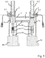
- the sanitary fitting shown comprises a housing 14 with a first housing area 14.1, a second housing area 14.2 and a third housing area 14.3, the sanitary fitting being arranged as a flush-mounted module in a wall 15 of a building.
- a fitting body 1 is arranged in the second housing area 14.2, the hot water connection 2 and cold water connection 3 of which are accessible from outside the housing 14.
- further components of the sanitary fitting are arranged on the fitting body 1.
- the mixed water generated in the fitting body 1 is either led to a mixed water extraction outlet 4a with an outlet 16 connected to it, or to a mixed water drainage outlet 4b. Underneath the mixed water drainage outlet 4b arranged in the first housing area 14.1, a funnel-shaped drainage water receptacle 12 is formed, which can be connected to a drainage line on the building side.
- a control unit 13 is arranged in the third housing area 14.3, which is connected to electric motors for operating valves in the fitting body.
- the sanitary fitting comprises a sequential mixing valve 7a, which is connected to the hot water connection 2 and the cold water connection 3 via corresponding lines.
- the sequential mixing valve 7a can be actuated by means of an electric motor 8a.
- the cold water pipe is used to measure the temperature of the A first temperature sensor 5.1 is assigned to the cold water and a second temperature sensor 5.2 is assigned to the hot water line for measuring the temperature of the hot water.
- a switchover valve 11 which can be actuated by means of an electric motor 8d.
- the mixed water can either be fed to a mixed water extraction line 9a or a mixed water discharge line 9b.
- the mixed water extraction line 9a has a mixed water extraction outlet 4a to which an outlet 16 is connected.
- the mixed water discharge line 9b leads to a mixed water discharge outlet 4b, from which the mixed water can freely fall into a funnel-shaped discharge water receptacle 12.
- the sensors 5, 6 and the motors 8 are connected to a control unit 13, not shown, for controlling or regulating the sanitary fitting.
- the sequential mixing valve 7a has no thermostat element and thus prevents, in its closed position, both the backflow of mixed water to the hot water connection 2 or to the cold water connection 3 and a flow from the hot water connection 2 to the cold water connection 3 or vice versa. It is therefore not necessary for a check valve to be arranged in the hot water line or cold water line upstream of the sequential mixing valve 7a.
- the mixing ratio of cold water and hot water depends on the position of the sequential mixing valve 7a, the control unit controlling or regulating the mixed water temperature to a predetermined value on the basis of the measurement signals from the temperature sensors 5.
- the switchover valve 11 is set such that the mixed water reaches the outlet 16.
- the sanitary fitting is flushed regularly to avoid stagnation water, for which purpose the switchover valve 11 directs the mixed water to the drainage water intake 12.
- the switchover valve 11 directs the mixed water to the drainage water intake 12.
- rinsing takes place exclusively with hot water for thermal disinfection.
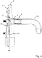
- the embodiment shown differs from that in Figure 3
- a first flow sensor 6.1 is assigned to the hot water line and a second flow sensor 6.2 is assigned to the cold water line.
- the mixed water temperature is thus set by the ratio of the degrees of opening of the hot water valve 8b and the cold water valve 8c. With this structure it is also possible to set different flows of the mixed water.
- a fitting body 1 with an H-shaped cross section which has a hot water connection 2 and a cold water connection 3 at the upper ends of the vertical legs.
- a hot water valve 7b is inserted into the fitting body 1, which valve can be actuated by means of an electric motor 8b.
- a cold water valve 7c is assigned to the cold water connection and is inserted into the fitting body 1 from the side opposite the cold water connection 3.
- the cold water valve 7c is coupled to an electric motor 8c.
- the drive shafts 10 of the electric motors 8b, 8c are each coupled by means of a coupling element 17 to the actuating shaft 18 of the valves 7b and 7c without the interposition of a gear, so that the position of the actuating shaft 18 is predetermined directly by the drive shaft 10.
- the hot water valve 7b and the cold water valve 7c are designed so that in their closed position the inflow and thus also the backflow of hot water or cold water into a mixed water line 9 is prevented. It is therefore not necessary for a check valve to be arranged in the line leading to the hot water connection 2 or the cold water connection 3.
- the mixed water line 9 formed in the horizontal section of the fitting body 1 leads to a mixed water outlet 4 which is connected to an outlet 16.
Landscapes
- Health & Medical Sciences (AREA)
- Life Sciences & Earth Sciences (AREA)
- Engineering & Computer Science (AREA)
- Hydrology & Water Resources (AREA)
- Public Health (AREA)
- Water Supply & Treatment (AREA)
- Multiple-Way Valves (AREA)
- Domestic Plumbing Installations (AREA)
- Electrically Driven Valve-Operating Means (AREA)
Priority Applications (3)
| Application Number | Priority Date | Filing Date | Title |
|---|---|---|---|
| EP19157181.9A EP3696332B1 (fr) | 2019-02-14 | 2019-02-14 | Robinetterie sanitaire à commande électrique |
| ES19157181T ES2911551T3 (es) | 2019-02-14 | 2019-02-14 | Robinetería sanitaria accionable eléctricamente |
| RU2020106827A RU2020106827A (ru) | 2019-02-14 | 2020-02-13 | Выполненный с возможностью электрического приведения в действие сантехнический смеситель |
Applications Claiming Priority (1)
| Application Number | Priority Date | Filing Date | Title |
|---|---|---|---|
| EP19157181.9A EP3696332B1 (fr) | 2019-02-14 | 2019-02-14 | Robinetterie sanitaire à commande électrique |
Publications (2)
| Publication Number | Publication Date |
|---|---|
| EP3696332A1 true EP3696332A1 (fr) | 2020-08-19 |
| EP3696332B1 EP3696332B1 (fr) | 2022-04-06 |
Family
ID=65440861
Family Applications (1)
| Application Number | Title | Priority Date | Filing Date |
|---|---|---|---|
| EP19157181.9A Active EP3696332B1 (fr) | 2019-02-14 | 2019-02-14 | Robinetterie sanitaire à commande électrique |
Country Status (3)
| Country | Link |
|---|---|
| EP (1) | EP3696332B1 (fr) |
| ES (1) | ES2911551T3 (fr) |
| RU (1) | RU2020106827A (fr) |
Cited By (2)
| Publication number | Priority date | Publication date | Assignee | Title |
|---|---|---|---|---|
| DE202020106196U1 (de) | 2020-10-29 | 2022-02-01 | Wwb Sweden Ab | Spüleinrichtung und Wasserauslaufarmatur |
| EP4001523A1 (fr) * | 2020-11-18 | 2022-05-25 | BLANCO GmbH + Co KG | Armature sanitaire, ainsi que système sanitaire |
Citations (6)
| Publication number | Priority date | Publication date | Assignee | Title |
|---|---|---|---|---|
| DE4431127A1 (de) * | 1994-09-01 | 1996-03-07 | Grohe Kg Hans | Sanitärventil mit einem Magnetventil |
| WO1998041787A1 (fr) | 1997-03-17 | 1998-09-24 | Ideal-Standard Gmbh | Robinet actionne electriquement |
| WO2011096961A1 (fr) * | 2010-02-02 | 2011-08-11 | Chung-Chia Chen | Robinet automatique sans contact |
| EP2543779A2 (fr) * | 2011-07-07 | 2013-01-09 | Markon Holdings Limited | Système de mélange d'eau, robinetterie sanitaire, système de remplissage de bain et système pour introduire sélectivement un additif dans un courant d'eau |
| DE102015000015A1 (de) * | 2015-01-07 | 2016-07-07 | Grohe Ag | Verfahren zur Bereitstellung eines Mischwassers mit einer Sanitärarmatur |
| US20160208947A1 (en) * | 2015-01-19 | 2016-07-21 | Moen Incorporated | Electronic plumbing fixture fitting with electronic valves having sequential operation |
-
2019
- 2019-02-14 EP EP19157181.9A patent/EP3696332B1/fr active Active
- 2019-02-14 ES ES19157181T patent/ES2911551T3/es active Active
-
2020
- 2020-02-13 RU RU2020106827A patent/RU2020106827A/ru unknown
Patent Citations (6)
| Publication number | Priority date | Publication date | Assignee | Title |
|---|---|---|---|---|
| DE4431127A1 (de) * | 1994-09-01 | 1996-03-07 | Grohe Kg Hans | Sanitärventil mit einem Magnetventil |
| WO1998041787A1 (fr) | 1997-03-17 | 1998-09-24 | Ideal-Standard Gmbh | Robinet actionne electriquement |
| WO2011096961A1 (fr) * | 2010-02-02 | 2011-08-11 | Chung-Chia Chen | Robinet automatique sans contact |
| EP2543779A2 (fr) * | 2011-07-07 | 2013-01-09 | Markon Holdings Limited | Système de mélange d'eau, robinetterie sanitaire, système de remplissage de bain et système pour introduire sélectivement un additif dans un courant d'eau |
| DE102015000015A1 (de) * | 2015-01-07 | 2016-07-07 | Grohe Ag | Verfahren zur Bereitstellung eines Mischwassers mit einer Sanitärarmatur |
| US20160208947A1 (en) * | 2015-01-19 | 2016-07-21 | Moen Incorporated | Electronic plumbing fixture fitting with electronic valves having sequential operation |
Cited By (2)
| Publication number | Priority date | Publication date | Assignee | Title |
|---|---|---|---|---|
| DE202020106196U1 (de) | 2020-10-29 | 2022-02-01 | Wwb Sweden Ab | Spüleinrichtung und Wasserauslaufarmatur |
| EP4001523A1 (fr) * | 2020-11-18 | 2022-05-25 | BLANCO GmbH + Co KG | Armature sanitaire, ainsi que système sanitaire |
Also Published As
| Publication number | Publication date |
|---|---|
| EP3696332B1 (fr) | 2022-04-06 |
| RU2020106827A (ru) | 2021-08-13 |
| ES2911551T3 (es) | 2022-05-19 |
Similar Documents
| Publication | Publication Date | Title |
|---|---|---|
| EP0910712B1 (fr) | Element de robinetterie pour l'ecoulement d'eau | |
| EP2946041B1 (fr) | Robinet sanitaire | |
| DE69122165T2 (de) | Regelgerät für Durchfluss und Temperatur von Fluiden | |
| EP2387740B1 (fr) | Dispositif mitigeur à régulation électronique pour l'eau de distribution | |
| EP4079980B1 (fr) | Système de conduite d'eau potable doté d'un réservoir de chasse d'eau | |
| EP3696332B1 (fr) | Robinetterie sanitaire à commande électrique | |
| DE102015001208B4 (de) | Sanitärarmatur | |
| EP3533941B1 (fr) | Robinet mélangeur | |
| AT519481B1 (de) | Endständige Sanitärarmatur | |
| DE29720701U1 (de) | Thermostatgeregelte Mischbatterie für automatisch gesteuertes Wechselduschen | |
| EP4117801A1 (fr) | Tête de filtre et kit d'extension pour une tête de filtre | |
| DE10119690C5 (de) | Sanitärinstallation in einem Bad | |
| DE3025603A1 (de) | Elektronisch gesteuerte waschtischarmatur | |
| DE29620414U1 (de) | Vorrichtung zur wiederholbaren Dosierung von Fluids | |
| EP2386693B1 (fr) | Armature de table de lavage dotée d'un élément de limitation de température de sécurité | |
| EP3705641B1 (fr) | Ensemble pourvu de sortie d'eau et mélangeur pour une douche | |
| DE202006017900U1 (de) | Fluidtechnische Steuerung und Regelung von Druck, Temperatur und Volumen | |
| EP2543780A1 (fr) | Module et système de douche doté d'une commande électronique | |
| DE19649937C2 (de) | Badewannenarmatur mit integrierter Schmutzwasserrücklaufsicherung | |
| EP3924651B1 (fr) | Unité fonctionnelle | |
| AT12050U1 (de) | Verfahren zur steuerung der mischwassertemperatur | |
| WO2019233544A1 (fr) | Soupape de sécurité et procédé de commande d'une soupape de sécurité | |
| DE10111578C1 (de) | Sanitäre Wandarmatur | |
| DE202008012727U1 (de) | Elektronisch steuerbare Armatur zum Mischen von kaltem und warmem Wasser, insbesondere für einen Waschtisch | |
| DE102022129751A1 (de) | Verfahren zum Betreiben einer Sanitärarmatur und Sanitärarmatur |
Legal Events
| Date | Code | Title | Description |
|---|---|---|---|
| PUAI | Public reference made under article 153(3) epc to a published international application that has entered the european phase |
Free format text: ORIGINAL CODE: 0009012 |
|
| STAA | Information on the status of an ep patent application or granted ep patent |
Free format text: STATUS: THE APPLICATION HAS BEEN PUBLISHED |
|
| AK | Designated contracting states |
Kind code of ref document: A1 Designated state(s): AL AT BE BG CH CY CZ DE DK EE ES FI FR GB GR HR HU IE IS IT LI LT LU LV MC MK MT NL NO PL PT RO RS SE SI SK SM TR |
|
| AX | Request for extension of the european patent |
Extension state: BA ME |
|
| STAA | Information on the status of an ep patent application or granted ep patent |
Free format text: STATUS: REQUEST FOR EXAMINATION WAS MADE |
|
| 17P | Request for examination filed |
Effective date: 20201029 |
|
| RBV | Designated contracting states (corrected) |
Designated state(s): AL AT BE BG CH CY CZ DE DK EE ES FI FR GB GR HR HU IE IS IT LI LT LU LV MC MK MT NL NO PL PT RO RS SE SI SK SM TR |
|
| STAA | Information on the status of an ep patent application or granted ep patent |
Free format text: STATUS: EXAMINATION IS IN PROGRESS |
|
| 17Q | First examination report despatched |
Effective date: 20210331 |
|
| GRAP | Despatch of communication of intention to grant a patent |
Free format text: ORIGINAL CODE: EPIDOSNIGR1 |
|
| STAA | Information on the status of an ep patent application or granted ep patent |
Free format text: STATUS: GRANT OF PATENT IS INTENDED |
|
| INTG | Intention to grant announced |
Effective date: 20210928 |
|
| GRAS | Grant fee paid |
Free format text: ORIGINAL CODE: EPIDOSNIGR3 |
|
| GRAA | (expected) grant |
Free format text: ORIGINAL CODE: 0009210 |
|
| STAA | Information on the status of an ep patent application or granted ep patent |
Free format text: STATUS: THE PATENT HAS BEEN GRANTED |
|
| AK | Designated contracting states |
Kind code of ref document: B1 Designated state(s): AL AT BE BG CH CY CZ DE DK EE ES FI FR GB GR HR HU IE IS IT LI LT LU LV MC MK MT NL NO PL PT RO RS SE SI SK SM TR |
|
| REG | Reference to a national code |
Ref country code: GB Ref legal event code: FG4D Free format text: NOT ENGLISH |
|
| REG | Reference to a national code |
Ref country code: CH Ref legal event code: EP |
|
| REG | Reference to a national code |
Ref country code: AT Ref legal event code: REF Ref document number: 1481456 Country of ref document: AT Kind code of ref document: T Effective date: 20220415 |
|
| REG | Reference to a national code |
Ref country code: IE Ref legal event code: FG4D Free format text: LANGUAGE OF EP DOCUMENT: GERMAN |
|
| REG | Reference to a national code |
Ref country code: DE Ref legal event code: R096 Ref document number: 502019003918 Country of ref document: DE |
|
| REG | Reference to a national code |
Ref country code: ES Ref legal event code: FG2A Ref document number: 2911551 Country of ref document: ES Kind code of ref document: T3 Effective date: 20220519 |
|
| REG | Reference to a national code |
Ref country code: LT Ref legal event code: MG9D |
|
| REG | Reference to a national code |
Ref country code: NL Ref legal event code: MP Effective date: 20220406 |
|
| PG25 | Lapsed in a contracting state [announced via postgrant information from national office to epo] |
Ref country code: NL Free format text: LAPSE BECAUSE OF FAILURE TO SUBMIT A TRANSLATION OF THE DESCRIPTION OR TO PAY THE FEE WITHIN THE PRESCRIBED TIME-LIMIT Effective date: 20220406 |
|
| PG25 | Lapsed in a contracting state [announced via postgrant information from national office to epo] |
Ref country code: SE Free format text: LAPSE BECAUSE OF FAILURE TO SUBMIT A TRANSLATION OF THE DESCRIPTION OR TO PAY THE FEE WITHIN THE PRESCRIBED TIME-LIMIT Effective date: 20220406 Ref country code: PT Free format text: LAPSE BECAUSE OF FAILURE TO SUBMIT A TRANSLATION OF THE DESCRIPTION OR TO PAY THE FEE WITHIN THE PRESCRIBED TIME-LIMIT Effective date: 20220808 Ref country code: NO Free format text: LAPSE BECAUSE OF FAILURE TO SUBMIT A TRANSLATION OF THE DESCRIPTION OR TO PAY THE FEE WITHIN THE PRESCRIBED TIME-LIMIT Effective date: 20220706 Ref country code: LT Free format text: LAPSE BECAUSE OF FAILURE TO SUBMIT A TRANSLATION OF THE DESCRIPTION OR TO PAY THE FEE WITHIN THE PRESCRIBED TIME-LIMIT Effective date: 20220406 Ref country code: HR Free format text: LAPSE BECAUSE OF FAILURE TO SUBMIT A TRANSLATION OF THE DESCRIPTION OR TO PAY THE FEE WITHIN THE PRESCRIBED TIME-LIMIT Effective date: 20220406 Ref country code: GR Free format text: LAPSE BECAUSE OF FAILURE TO SUBMIT A TRANSLATION OF THE DESCRIPTION OR TO PAY THE FEE WITHIN THE PRESCRIBED TIME-LIMIT Effective date: 20220707 Ref country code: FI Free format text: LAPSE BECAUSE OF FAILURE TO SUBMIT A TRANSLATION OF THE DESCRIPTION OR TO PAY THE FEE WITHIN THE PRESCRIBED TIME-LIMIT Effective date: 20220406 Ref country code: BG Free format text: LAPSE BECAUSE OF FAILURE TO SUBMIT A TRANSLATION OF THE DESCRIPTION OR TO PAY THE FEE WITHIN THE PRESCRIBED TIME-LIMIT Effective date: 20220706 |
|
| PG25 | Lapsed in a contracting state [announced via postgrant information from national office to epo] |
Ref country code: RS Free format text: LAPSE BECAUSE OF FAILURE TO SUBMIT A TRANSLATION OF THE DESCRIPTION OR TO PAY THE FEE WITHIN THE PRESCRIBED TIME-LIMIT Effective date: 20220406 Ref country code: PL Free format text: LAPSE BECAUSE OF FAILURE TO SUBMIT A TRANSLATION OF THE DESCRIPTION OR TO PAY THE FEE WITHIN THE PRESCRIBED TIME-LIMIT Effective date: 20220406 Ref country code: LV Free format text: LAPSE BECAUSE OF FAILURE TO SUBMIT A TRANSLATION OF THE DESCRIPTION OR TO PAY THE FEE WITHIN THE PRESCRIBED TIME-LIMIT Effective date: 20220406 Ref country code: IS Free format text: LAPSE BECAUSE OF FAILURE TO SUBMIT A TRANSLATION OF THE DESCRIPTION OR TO PAY THE FEE WITHIN THE PRESCRIBED TIME-LIMIT Effective date: 20220806 |
|
| REG | Reference to a national code |
Ref country code: DE Ref legal event code: R097 Ref document number: 502019003918 Country of ref document: DE |
|
| PG25 | Lapsed in a contracting state [announced via postgrant information from national office to epo] |
Ref country code: SM Free format text: LAPSE BECAUSE OF FAILURE TO SUBMIT A TRANSLATION OF THE DESCRIPTION OR TO PAY THE FEE WITHIN THE PRESCRIBED TIME-LIMIT Effective date: 20220406 Ref country code: SK Free format text: LAPSE BECAUSE OF FAILURE TO SUBMIT A TRANSLATION OF THE DESCRIPTION OR TO PAY THE FEE WITHIN THE PRESCRIBED TIME-LIMIT Effective date: 20220406 Ref country code: RO Free format text: LAPSE BECAUSE OF FAILURE TO SUBMIT A TRANSLATION OF THE DESCRIPTION OR TO PAY THE FEE WITHIN THE PRESCRIBED TIME-LIMIT Effective date: 20220406 Ref country code: EE Free format text: LAPSE BECAUSE OF FAILURE TO SUBMIT A TRANSLATION OF THE DESCRIPTION OR TO PAY THE FEE WITHIN THE PRESCRIBED TIME-LIMIT Effective date: 20220406 Ref country code: DK Free format text: LAPSE BECAUSE OF FAILURE TO SUBMIT A TRANSLATION OF THE DESCRIPTION OR TO PAY THE FEE WITHIN THE PRESCRIBED TIME-LIMIT Effective date: 20220406 Ref country code: CZ Free format text: LAPSE BECAUSE OF FAILURE TO SUBMIT A TRANSLATION OF THE DESCRIPTION OR TO PAY THE FEE WITHIN THE PRESCRIBED TIME-LIMIT Effective date: 20220406 |
|
| PLBE | No opposition filed within time limit |
Free format text: ORIGINAL CODE: 0009261 |
|
| STAA | Information on the status of an ep patent application or granted ep patent |
Free format text: STATUS: NO OPPOSITION FILED WITHIN TIME LIMIT |
|
| 26N | No opposition filed |
Effective date: 20230110 |
|
| PG25 | Lapsed in a contracting state [announced via postgrant information from national office to epo] |
Ref country code: AL Free format text: LAPSE BECAUSE OF FAILURE TO SUBMIT A TRANSLATION OF THE DESCRIPTION OR TO PAY THE FEE WITHIN THE PRESCRIBED TIME-LIMIT Effective date: 20220406 |
|
| PG25 | Lapsed in a contracting state [announced via postgrant information from national office to epo] |
Ref country code: SI Free format text: LAPSE BECAUSE OF FAILURE TO SUBMIT A TRANSLATION OF THE DESCRIPTION OR TO PAY THE FEE WITHIN THE PRESCRIBED TIME-LIMIT Effective date: 20220406 |
|
| PG25 | Lapsed in a contracting state [announced via postgrant information from national office to epo] |
Ref country code: MC Free format text: LAPSE BECAUSE OF FAILURE TO SUBMIT A TRANSLATION OF THE DESCRIPTION OR TO PAY THE FEE WITHIN THE PRESCRIBED TIME-LIMIT Effective date: 20220406 |
|
| REG | Reference to a national code |
Ref country code: CH Ref legal event code: PL |
|
| REG | Reference to a national code |
Ref country code: BE Ref legal event code: MM Effective date: 20230228 |
|
| PG25 | Lapsed in a contracting state [announced via postgrant information from national office to epo] |
Ref country code: LU Free format text: LAPSE BECAUSE OF NON-PAYMENT OF DUE FEES Effective date: 20230214 Ref country code: LI Free format text: LAPSE BECAUSE OF NON-PAYMENT OF DUE FEES Effective date: 20230228 Ref country code: CH Free format text: LAPSE BECAUSE OF NON-PAYMENT OF DUE FEES Effective date: 20230228 |
|
| REG | Reference to a national code |
Ref country code: IE Ref legal event code: MM4A |
|
| PG25 | Lapsed in a contracting state [announced via postgrant information from national office to epo] |
Ref country code: IE Free format text: LAPSE BECAUSE OF NON-PAYMENT OF DUE FEES Effective date: 20230214 |
|
| PG25 | Lapsed in a contracting state [announced via postgrant information from national office to epo] |
Ref country code: BE Free format text: LAPSE BECAUSE OF NON-PAYMENT OF DUE FEES Effective date: 20230228 |
|
| PG25 | Lapsed in a contracting state [announced via postgrant information from national office to epo] |
Ref country code: BG Free format text: LAPSE BECAUSE OF FAILURE TO SUBMIT A TRANSLATION OF THE DESCRIPTION OR TO PAY THE FEE WITHIN THE PRESCRIBED TIME-LIMIT Effective date: 20220406 |
|
| PG25 | Lapsed in a contracting state [announced via postgrant information from national office to epo] |
Ref country code: BG Free format text: LAPSE BECAUSE OF FAILURE TO SUBMIT A TRANSLATION OF THE DESCRIPTION OR TO PAY THE FEE WITHIN THE PRESCRIBED TIME-LIMIT Effective date: 20220406 |
|
| REG | Reference to a national code |
Ref country code: AT Ref legal event code: MM01 Ref document number: 1481456 Country of ref document: AT Kind code of ref document: T Effective date: 20240214 |
|
| PG25 | Lapsed in a contracting state [announced via postgrant information from national office to epo] |
Ref country code: AT Free format text: LAPSE BECAUSE OF NON-PAYMENT OF DUE FEES Effective date: 20240214 |
|
| PGFP | Annual fee paid to national office [announced via postgrant information from national office to epo] |
Ref country code: TR Payment date: 20250130 Year of fee payment: 7 |
|
| PG25 | Lapsed in a contracting state [announced via postgrant information from national office to epo] |
Ref country code: CY Free format text: LAPSE BECAUSE OF FAILURE TO SUBMIT A TRANSLATION OF THE DESCRIPTION OR TO PAY THE FEE WITHIN THE PRESCRIBED TIME-LIMIT; INVALID AB INITIO Effective date: 20190214 |
|
| PG25 | Lapsed in a contracting state [announced via postgrant information from national office to epo] |
Ref country code: HU Free format text: LAPSE BECAUSE OF FAILURE TO SUBMIT A TRANSLATION OF THE DESCRIPTION OR TO PAY THE FEE WITHIN THE PRESCRIBED TIME-LIMIT; INVALID AB INITIO Effective date: 20190214 |
|
| REG | Reference to a national code |
Ref country code: DE Ref legal event code: R082 Ref document number: 502019003918 Country of ref document: DE Representative=s name: DIPAS PATENTANWALTS GMBH, DE |
|
| PGFP | Annual fee paid to national office [announced via postgrant information from national office to epo] |
Ref country code: GB Payment date: 20260227 Year of fee payment: 8 |
|
| PGFP | Annual fee paid to national office [announced via postgrant information from national office to epo] |
Ref country code: ES Payment date: 20260302 Year of fee payment: 8 |
|
| PGFP | Annual fee paid to national office [announced via postgrant information from national office to epo] |
Ref country code: DE Payment date: 20260227 Year of fee payment: 8 |
|
| PGFP | Annual fee paid to national office [announced via postgrant information from national office to epo] |
Ref country code: AT Payment date: 20260410 Year of fee payment: 5 |
|
| PGFP | Annual fee paid to national office [announced via postgrant information from national office to epo] |
Ref country code: IT Payment date: 20260219 Year of fee payment: 8 |
|
| PGFP | Annual fee paid to national office [announced via postgrant information from national office to epo] |
Ref country code: FR Payment date: 20260225 Year of fee payment: 8 |