EP3696335B1 - Kanalinspektions- und/oder wartungssystem - Google Patents
Kanalinspektions- und/oder wartungssystem Download PDFInfo
- Publication number
- EP3696335B1 EP3696335B1 EP19156998.7A EP19156998A EP3696335B1 EP 3696335 B1 EP3696335 B1 EP 3696335B1 EP 19156998 A EP19156998 A EP 19156998A EP 3696335 B1 EP3696335 B1 EP 3696335B1
- Authority
- EP
- European Patent Office
- Prior art keywords
- guide device
- telescopic
- guide
- channel
- profile
- Prior art date
- Legal status (The legal status is an assumption and is not a legal conclusion. Google has not performed a legal analysis and makes no representation as to the accuracy of the status listed.)
- Active
Links
Images

Classifications
-
- F—MECHANICAL ENGINEERING; LIGHTING; HEATING; WEAPONS; BLASTING
- F16—ENGINEERING ELEMENTS AND UNITS; GENERAL MEASURES FOR PRODUCING AND MAINTAINING EFFECTIVE FUNCTIONING OF MACHINES OR INSTALLATIONS; THERMAL INSULATION IN GENERAL
- F16L—PIPES; JOINTS OR FITTINGS FOR PIPES; SUPPORTS FOR PIPES, CABLES OR PROTECTIVE TUBING; MEANS FOR THERMAL INSULATION IN GENERAL
- F16L55/00—Devices or appurtenances for use in, or in connection with, pipes or pipe systems
- F16L55/26—Pigs or moles, i.e. devices movable in a pipe or conduit with or without self-contained propulsion means
- F16L55/28—Constructional aspects
- F16L55/40—Constructional aspects of the body
-
- E—FIXED CONSTRUCTIONS
- E03—WATER SUPPLY; SEWERAGE
- E03F—SEWERS; CESSPOOLS
- E03F7/00—Other installations or implements for operating sewer systems, e.g. for preventing or indicating stoppage; Emptying cesspools
- E03F7/12—Installations enabling inspection personnel to drive along sewer canals
-
- G—PHYSICS
- G01—MEASURING; TESTING
- G01M—TESTING STATIC OR DYNAMIC BALANCE OF MACHINES OR STRUCTURES; TESTING OF STRUCTURES OR APPARATUS, NOT OTHERWISE PROVIDED FOR
- G01M3/00—Investigating fluid-tightness of structures
- G01M3/005—Investigating fluid-tightness of structures using pigs or moles
-
- F—MECHANICAL ENGINEERING; LIGHTING; HEATING; WEAPONS; BLASTING
- F16—ENGINEERING ELEMENTS AND UNITS; GENERAL MEASURES FOR PRODUCING AND MAINTAINING EFFECTIVE FUNCTIONING OF MACHINES OR INSTALLATIONS; THERMAL INSULATION IN GENERAL
- F16L—PIPES; JOINTS OR FITTINGS FOR PIPES; SUPPORTS FOR PIPES, CABLES OR PROTECTIVE TUBING; MEANS FOR THERMAL INSULATION IN GENERAL
- F16L2101/00—Uses or applications of pigs or moles
- F16L2101/30—Inspecting, measuring or testing
Definitions
- the invention relates to a channel inspection and/or maintenance system which has at least one carrier system, a satellite system and a guide device, wherein the guide device is provided for introducing the satellite system from a main channel into a side channel branching off from the main channel.
- satellite systems In the field of sewer inspection or sewer maintenance, so-called satellite systems are often used, which can be introduced from a carriage into a side channel leading off from a main channel.
- the satellite system can be designed as a push camera to inspect the side channel.
- the push system can also have manipulators, for example to maintain or clean the side channel.
- An example of such a manipulator is a flushing device or flushing nozzle with which the side channel can be cleaned.
- the carriage usually has a guide device designed as a guide tube, whereby the guide tube has a certain length.
- the satellite system is pushed from the carriage into the side channel via the guide tube.
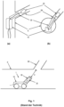
- Fig.1 shows a schematic representation of a channel inspection and/or maintenance system known from the prior art, which is arranged in a main channel K.
- a such a system is shown in a view from above, in figure (b) in a view from the front, and in figure (c) in a side view within a channel system.
- the guide device 30, designed as a guide tube, is arranged on the carriage 10, via which the satellite system 20 can be pushed from the main channel K into the side channel SK.
- the guide tube 30 is positioned or aligned in such a way that the front or free end of the guide tube 30 points towards the side channel SK to be inspected or slightly protrudes into this side channel or rests against it.
- the satellite system 20 is then pushed into the side channel SK from the carriage 10 via this guide tube and can then be pushed forward in the side channel SK for the purpose of inspection and/or maintenance.
- the disadvantage is that for a large number of different channel diameters, a corresponding number of guide pipes must be kept in stock in order to be able to equip a carriage with the guide pipe suitable for the respective channel diameter.
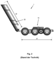
- Fig. 2 shows a concrete, state-of-the-art sewer inspection and/or maintenance system 1 from iPEK International GmbH, Sulzberg, Germany.
- This sewer inspection and/or maintenance system with the guide pipe 30 shown here is only suitable for use in sewers with a maximum diameter of 70 cm.
- the carriage 10 For use in sewers with a diameter of more than 70 cm, the carriage 10 must be equipped with a correspondingly longer guide pipe.
- the object of the present invention is therefore to provide solutions which at least partially avoid the disadvantages mentioned in the prior art and which largely make an exchange of guide tubes for the purpose of adapting the guide tube to the channel diameter superfluous.
- the extendable design of the guide device means that it can have very compact dimensions in the stowed position, so that the entire sewer inspection and/or maintenance system can be transported fully assembled through the shaft into the sewer. This avoids having to lower the carrier system and guide device separately through the shaft into the sewer.
- the effective length of the guide device in the channel can be changed so that the length of the guide device can be adapted to changing diameters of the main channel, for example. This avoids having to keep guide pipes or guide devices of different lengths for different channel diameters and having to mount a guide pipe of the appropriate length on the carriage or carrier system depending on the channel diameter.
- a first section of the guide device can be designed to be extendable and a second section of the guide device can be designed to be foldable.
- the guide device can have extendable and foldable and rollable sections.
- a stowed position of the guidance system is the position or state in which the guidance system has the smallest dimensions or the smallest effective length for guiding the satellite system. Depending on the specific design of the guidance system, it can also be used in the stowed position to guide the satellite system.
- a use position of the guidance system is that position or state in which the effective length along which the satellite system is guided is greater than that in the stowed position.
- the guide device is detachably coupled to the carrier system.
- the guide device Due to the detachable arrangement or coupling of the guide device to the support system, the guide device can be removed when not in use or in the event that the guide device is not required for inspection or maintenance.
- a guide device that is suitable for duct diameters of up to 1.5 meters for example, can be replaced by a guide device that is suitable for duct diameters of over 1.5 meters.
- the effective length of the guidance device along which the satellite system can be guided during a movement relative to the carrier system can be increased by extending the guidance device.
- the travel path of the satellite system relative to the guidance device can be increased.
- the travel path is greater when the guidance device is extended than when the guidance device is not extended.
- the guide device can be reversibly extendable from the stowed position into at least one use position.
- the guide device can be designed to be telescopic and can be extended from the stowed position into at least one use position.
- telescopic elements of the telescopic guide device that can be moved relative to one another are designed as solid tube profiles and/or as partial tube profiles.
- tubes with a round, elliptical or rectangular profile cross-section can be used as solid tube profiles for the telescopic elements.
- Partial pipe profiles are pipes with, for example, a round, an elliptical or a rectangular profile cross-section, where a part of the side wall of the pipe is recessed between one pipe end and the other pipe end. remains so that the remaining side wall of the pipe forms two profile edges that extend from one end of the pipe to the other.
- these profile edges run parallel to each other and parallel to the longitudinal axis of the pipe.
- Fig.7 Two examples of such a partial tube profile are shown.
- the guide device can have a number of pivoting elements which are coupled to one another in pairs and can be pivoted relative to one another, wherein the guide device can be folded open from the stowed position into the at least one use position.
- the swivel elements can be designed as solid tube profiles and/or as partial tube profiles.
- the guide device can comprise a roll-up spring plate, wherein the spring plate can be rolled out from the stowed position into the at least one use position.
- the spring plate can be adapted to take the form of a partial tubular profile in the position of use.
- the guide device can be associated with a drive unit which is adapted to extend the guide device from the stowed position into the at least one use position.
- the solution according to the invention makes it possible, on the one hand, to use one and the same guide device for channels with different diameters.
- the guide device can be brought into a stowed position so compactly that the carrier system, including the guide device arranged on it, can be brought into the channel through a shaft and can also be taken out of the channel again through the shaft.
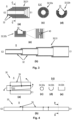
- Fig.3 shows a guide device 30 of a sewer inspection and/or maintenance system according to the invention, wherein the guide device 30 is designed here as a telescopic guide device 31.
- Figure (a) shows a longitudinal section of a telescopic guide device 31 in a stowed position in which the telescopic elements 32 which can be displaced relative to one another are fully retracted.
- Figure (b) shows the telescopic guide device 31 in a use position in which the telescopic elements 32 which can be displaced relative to one another are fully extended.
- the telescopic guide device 31 shown here has four telescopic elements 32 that can be moved relative to one another and are designed here as elements that can be moved into one another. If required, however, more than four or fewer than four telescopic elements 32 that can be moved relative to one another can also be provided.
- the effective guide length for guiding the satellite system can be increased by about four times. With a length of a telescopic element 32 of, for example, 50 centimeters, the effective length of the telescopic guide device 31 can be increased to up to about 2 meters, so that a channel inspection and/or maintenance system can be used in channels that have a diameter of between about 50 centimeters and 2 meters.
- Figure (c) shows a cross-section of the telescopic guide device 31 shown in figure (a) along the section axis CC.
- the telescopic guide device 31 consists of telescopic elements 32 that can be moved into one another and are each designed as a solid tube profile 32a with an approximately circular cross-section or profile cross-section.
- Other profile cross-sections are possible, such as elliptical or rectangular profile cross-sections.
- Figure (d) shows a cross-section of a telescopic guide device in which the telescopic elements 32 which can be moved into one another are designed as partial tubular profiles 32b. Examples of a partial tubular profile are given with reference to Fig.7
- the partial tube profiles 32b have axially and preferably parallel profile edges 33.
- Figure (e) shows a cross-section of a telescopic guide device 31, wherein the telescopic elements 32 which can be displaced into one another are designed as partial tubular profiles 32b, wherein the profile cross-sections have the shape of a U-profile.
- the telescopic guide device 31 can have guide means 40 along which the individual telescopic elements are moved relative to one another when extending or retracting.
- a tongue-and-groove linear guide 40 can be provided between two adjacent telescopic elements 32.
- Such guide means 40 can also be provided in the profile cross-sections shown in Figure (c) and Figure (d).
- telescopic elements designed as a solid tube profile 32a can be combined with telescopic elements designed as a partial tube profile 32b, so that the guide device 31 can, for example, be designed in sections as a solid tube profile and in sections as a partial tube profile.
- Fig.4 shows an embodiment of a guide device of a sewer inspection and/or maintenance system not according to the invention.
- the guide device 30 is designed here as a foldable guide device which has a number of pivoting elements 34.
- the pivoting elements 34 are coupled together in pairs so that they can be pivoted relative to one another and can be folded into a compact storage position, as shown in Figure (a).
- the guide device shown in Figure (a) is shown in Figure (b) in the position of use, ie in the unfolded state.
- the individual pivoting elements 34 of the guide device 30 can be coupled to one another, for example by means of hinges, which can be driven by adjusting means, preferably independently of one another.
- the pivoting elements 34 of the guide device 30 are preferably arranged relative to one another in such a way that the entire guide device 30 is aligned in a straight line, so that the satellite system 20 can be guided straight or linearly along the guide device 30.
- the pivoting elements 34 themselves can also have a slightly curved shape.
- FIG. 4 shows a swivel element 34 with a largely circular profile cross section.
- the solid tube profile according to figure (c) can also have an elliptical, rectangular or polygonal profile cross section.
- Figure (d) shows a swivel element 34 which is designed as a partial tube profile 32b.
- Figure (d) shows a swivel element 34 with a U-profile-shaped cross section.
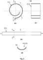
- Fig.5 shows an embodiment of a guide device 30 of a channel inspection and/or maintenance system not according to the invention.
- the guide device 30 here has a resilient or flexible element 35, which in the embodiment shown here is designed as a spring plate.
- the spring plate 35 is shown in a stowed position in which the spring plate 35 is rolled up.
- the spring plate 35 shown in Figure (a) is shown in a use position in which the spring plate 35 is completely rolled out.
- the spring plate 35 In the unrolled state, i.e. in the position of use, the spring plate 35 forms a largely straight or linear guide for the satellite system 20. However, it is also possible for the spring plate 35 to be slightly curved in the position of use, i.e. in the unrolled state, and thus enables a curved guide of the satellite system 20 along the guide device 30.
- the spring plate 35 In the stowed position, i.e. when rolled up, the spring plate 35 is largely flat, as can be seen in Figure (c), wherein Figure (c) shows a cross-section along the section axis E-E.
- Figure (d) shows a cross-section along the section axis F-F of the spring plate 35 in the unrolled state or in the position of use.
- the shape of the half-shell or the partial tubular profile shape in the unrolled state can be embossed into the spring plate 35, so that the spring plate 35 automatically assumes the shape of the half-shell or the partial tubular profile when rolled out or after rolling out.
- the spring plate 35 is designed in such a way that it can be brought back into the stowed position against its spring force, ie it can be rolled up.
- Fig.6 shows a sewer inspection and/or maintenance system 1 according to the invention with a guide device 30 according to the invention arranged thereon, wherein in figure (a) the guide device 30 is shown in a stowed position and in figure (b) the guide device 30 is shown in a use position.
- the guide device 30 shown is, for example, a telescopic guide device 31 which can be extended to increase the effective guide length.
- the telescopic guide device 31 shown has four telescopic elements 32 which can be moved into one another, so that the effective guide length d2 of the telescopic guide device 31 in the use position is approximately four times as long as the effective guide length d2 of the telescopic guide device 31 in the stowed position.
- the guide device 30 is arranged with its first end E1 on the carrier system 10, preferably pivotably arranged on the carrier system 10.
- the carrier system 10 is in the Figure 6
- the embodiment of the sewer inspection and/or maintenance system according to the invention shown is designed as a carriage.
- the guide devices shown can also be arranged with the first end E1 on the carrier system 10. These guide devices 30 can also be arranged pivotably on the carrier system.
- the guide device 30 shown can also be arranged with the second end E2 on the carrier system 10, so that the diameter of the guide device 30 in the position of use gradually increases in the direction of the free end of the guide device.
- a sliding eel can also be used as a carrier system, with the front, ie the guide device 30 can be arranged at the free end of the sliding eel, preferably can be arranged pivotably.
- the satellite system 20 is also brought into the channel and pushed forward in the channel. After reaching the side channel to be inspected, the satellite system 20 can be pushed into the side channel by the pusher eel via the guide device 30.
- actuating means or drive units can be provided with which the respective guide device 30 can be brought from a stowed position into a use position or from the use position back into the stowed position.
- These actuating means or drive units can be arranged either on the carrier system 10 or on the guide device 30 itself.
- spindle drives or Bowden cables can be used as adjusting means.
- the telescopic elements 32 themselves can be designed as a spindle, so that one telescopic element can be displaced relative to the other telescopic element by rotating about its longitudinal axis.
- servo motors In a foldable guide device 30 not according to the invention, servo motors, spring mechanisms, cables or Bowden cables as well as combinations thereof are also possible as adjusting means.
- a roller drive can be provided as an actuating means, which pushes the guide device out of a roll-up container.
- the satellite system 20 itself can also be used as an actuating means, so that moving the satellite system 20 along the guide device 30 causes the guide device 30 to extend.
- the satellite system 20 can, for example, be detachably coupled to the innermost of the telescopic elements 32 that can be moved into one another, so that the satellite system 20 takes the innermost of the telescopic elements 32 with it when it is advanced.
- the telescopic elements 32 can be coupled to one another in such a way that a telescopic element takes the next largest telescopic element with it.
- the satellite system 20 can be decoupled from the innermost telescopic element, so that the satellite system 20 can be moved relative to this telescopic element and pushed into the side channel.
- the satellite system can be coupled again with the innermost telescopic element 32, so that in the further course the telescopic elements 32 are again pushed into each other and the telescopic guide device 31 is thus brought back into the stowed position. After reaching the stowed position, the satellite system can be uncoupled again from the innermost telescopic element.
- the swivel elements 34 can be assigned spring elements that hold the swivel elements in the stowed position.
- the individual swivel elements can then be opened one after the other against the spring force of the spring elements. Due to the relatively high rigidity of the cable or the sliding eel of the satellite system, the opened swivel elements are held in the opened state.
- the opened swivel elements are released one after the other and the spring force of the spring elements causes the swivel elements to be folded together again.
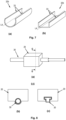
- the spring force of the spring plate 35 can be used.
- the spring plate is rolled out against its spring force.
- the spring force of the spring plate causes the spring plate to roll up automatically and thus return to the stowed position.
- Fig.7 shows two examples of a telescopic element 32 designed as a partial tubular profile 32b.
- the partial tubular profile 32b has a circular ring-segment-shaped cross-section, ie a section of the side wall of the tube is recessed between one end of the tube and the other end of the tube, so that the partial tubular profile 32b has two profile edges 33 running parallel to the longitudinal axis LA and parallel to one another.
- Figure (b) shows a partial tubular profile 32b which has a substantially U-shaped cross-section.
- This partial tubular profile 32b shown in Figure (b) also has two profile edges 33 which run parallel to one another and parallel to the longitudinal axis LA.
- the partial tubular profiles used for a guide device 30 can also have a different profile cross-section.
- the only requirement is that the profile is suitable for safely guiding the satellite system along the carrier system and that the individual elements of the guide device within the meaning of the present invention are extendable or foldable or retractable and foldable.
- Fig.8 shows a further embodiment of a guidance device according to the invention with a satellite system arranged thereon, wherein in figure (a) the system is shown in a perspective view, and wherein in figures (b) and (c) two possible cross sections of the system are shown.
- the guide device 30 shown is a telescopic guide device with telescopic elements that can be moved relative to one another, such as in Fig.3 shown.
- the guide device 30 shown in Figure (b) has a round cross-section, while the guide device 30 shown in Figure (c) has a T-shaped cross-section.
- the guide device can have different cross-sections, it only has to be ensured that the individual telescopic elements can be moved relative to one another.
- the telescopic elements that can be moved relative to one another can be moved into one another.
- the guide device 30 is encompassed by the satellite system 20 ( Figure (b)) or partially encompassed ( Figure (c)), so that the satellite system 20 can be moved along the guide device 30.
- the guide device 30 can also be designed as a fold-out or roll-out guide device in a non-inventive embodiment, as in Fig.4 or. Fig.5 shown. After unfolding or rolling out the guide device, the satellite system 20, which completely or partially surrounds the guide device 30, can be moved along the guide device.
Landscapes
- Engineering & Computer Science (AREA)
- General Engineering & Computer Science (AREA)
- Life Sciences & Earth Sciences (AREA)
- Hydrology & Water Resources (AREA)
- Public Health (AREA)
- Water Supply & Treatment (AREA)
- Health & Medical Sciences (AREA)
- Physics & Mathematics (AREA)
- Chemical & Material Sciences (AREA)
- Combustion & Propulsion (AREA)
- General Physics & Mathematics (AREA)
- Mechanical Engineering (AREA)
- Sewage (AREA)
Description
- Die Erfindung betrifft ein Kanalinspektions- und /oder Wartungssystem, das zumindest ein Trägersystem, ein Satellitensystem und eine Führungseinrichtung aufweist, wobei die Führungseinrichtung dazu vorgesehen ist, das Satellitensystem aus einem Hauptkanal in einen vom Hauptkanal abzweigenden Seitenkanal einzuführen.
- Auf dem Gebiet der Kanalinspektion bzw. Kanalwartung werden häufig sogenannte Satellitensysteme verwendet, die von einem Fahrwagen aus in einen, von einem Hauptkanal abgehenden, Seitenkanal eingeführt werden können. Das Satellitensystem kann hierbei als Schiebekamera ausgebildet sein, um den Seitenkanal zu inspizieren. Alternativ oder zusätzlich kann das Schiebesystem auch Manipulatoren aufweisen, um beispielsweise den Seitenkanal zu warten bzw. zu reinigen. Ein Beispiel eines solchen Manipulators ist eine Spüleinrichtung bzw. Spüldüse, mit der der Seitenkanal gereinigt werden kann.
- Bei größeren Abständen zwischen dem Fahrwagen und dem Seitenkanal weist der Fahrwagen üblicherweise eine als Führungsrohr ausgestaltete Führungseinrichtung auf, wobei das Führungsrohr eine bestimmte Länge aufweist. Über das Führungsrohr wird das Satellitensystem vom Fahrwagen aus in den Seitenkanal hineingeschoben.
-
Fig. 1 zeigt eine schematische Darstellung eines aus dem Stand der Technik bekannten Kanalinspektions- und/oder Wartungssystems, das in einem Hauptkanal K angeordnet ist. In Abbildung (a) ist ein solches System in einer Ansicht von oben, in Abbildung (b) in einer Ansicht von vorne, und in Abbildung (c) in einer Seitenansicht innerhalb eines Kanalsystems gezeigt. - An dem Fahrwagen 10 ist die als Führungsrohr ausgestaltete Führungseinrichtung 30 angeordnet, über die das Satellitensystem 20 vom Hauptkanal K aus in den Seitenkanal SK eingeschoben werden kann. Hierbei wird das Führungsrohr 30 so positioniert bzw. ausgerichtet, dass das vordere bzw. freie Ende des Führungsrohres 30 zum zu inspizierenden Seitenkanal SK zeigt bzw. leicht in diesen Seitenkanal hineinragt oder an diesem anliegt. Das Satellitensystem 20 wird dann über dieses Führungsrohr vom Fahrwagen 10 aus in den Seitenkanal SK eingeschoben und kann dann in dem Seitenkanal SK zum Zwecke der Inspektion und/oder Wartung vorgeschoben werden.
- Bei Hauptkanälen mit unterschiedlichen Durchmessern ist es im Stand der Technik erforderlich unterschiedlich lange Führungsrohre bzw. Führungseinrichtungen 30 zu verwenden, um ein sicheres Einführen des Satellitensystems in einen vom Hauptkanal abzweigenden Seitenkanal zu gewährleisten.
- Bei Hauptkanälen mit kleinen Durchmessern können keine langen Führungsrohre verwendet werden, da ein langes Führungsrohr nicht mehr zum Seitenkanal hin ausgerichtet werden kann.
- Bei Hauptkanälen mit großen Durchmessern können hingegen kurze Führungsrohre 30, wie in Abbildung (c) gezeigt, nicht verwendet werden. Denn das Führungsrohr 30 kann zwar zum Seitenkanal SK hin ausgerichtet werden. Das Satellitensystem 20 kann allerdings aufgrund der Distanz d zwischen dem freien Ende des Führungsrohres 30 und dem Zugang zum Seitenkanal SK nicht mehr sicher in den Seitenkanal eingebracht werden.
- Je nach Durchmesser des Hauptkanals ist es daher notwendig, den Fahrwagen mit einem Führungsrohr zu bestücken, dessen Länge an den Durchmesser des Hauptkanals angepasst ist. Bei sich verjüngenden Hauptkanälen bzw. bei Hauptkanälen deren Durchmesser sich ändert, kann es zudem erforderlich sein, das Führungsrohr während einer Wartung bzw. einer Inspektion auszutauschen, um ein für den jeweiligen Kanaldurchmesser geeignetes Führungsrohr zu verwenden.
- Nachteilig ist demnach, dass für eine Vielzahl von unterschiedlichen Kanaldurchmessern eine entsprechende Anzahl von Führungsrohren vorgehalten werden muss, um einen Fahrwagen mit dem jeweils für den Kanaldurchmesser geeigneten Führungsrohr bestücken zu können.
- Bei Kanälen mit sehr großen Kanaldurchmessern, beispielsweise von zwei Metern und mehr, müssen demnach entsprechend lange Führungsrohre an dem Fahrwagen angeordnet werden. Hierbei ist es ein Nachteil, dass der Fahrwagen samt Führungsrohr meist zu groß ist, um ihn in einem Stück durch einen Schacht in den Hauptkanal zu bringen. Der Anwender des Kanalinspektions- und/oder Wartungssystems ist dadurch gezwungen, den Fahrwagen und das Führungsrohr getrennt voneinander durch den Schacht in den Hauptkanal abzulassen und die Montage des Führungsrohrs an dem Fahrwagen im Kanal durchzuführen. Für den Anwender ist dies mit zusätzlichen Gefahren und Aufwand verbunden. Dasselbe Problem stellt sich auch beim Herausziehen des Kanalinspektions- und/oder Wartungssystems durch den Schacht, d.h. vor dem Herausziehen des Systems muss das Führungsrohr vom Fahrwagen getrennt werden und der Fahrwagen und das Führungsrohr müssen getrennt voneinander durch den Schacht herausgezogen werden. Zudem erfordern Vorschriften aus dem Bereich Arbeits- und Personenschutz weitreichende Absicherungsmaßnahmen, wenn ein Anwender in den Schacht hinabsteigen muss.
-
Fig. 2 zeigt ein konkretes, aus dem Stand der Technik bekanntes Kanalinspektions- und/oder Wartungssystem 1 der iPEK International GmbH, Sulzberg, Deutschland. - Das Führungsrohr 30, das hier eine Länge d2 von etwa 50 cm aufweist, ist an einem Fahrwagen 10, der ebenfalls eine Länge d1 von etwa 50 cm aufweist, angeordnet. Dieses Kanalinspektions- und/oder Wartungssystem mit dem hier gezeigten Führungsrohr 30 eignet sich lediglich für den Einsatz in Kanälen mit einem Durchmesser von maximal 70 cm. Für den Einsatz in Kanälen mit einem Durchmesser von mehr als 70 cm muss der Fahrwagen 10 mit einem entsprechend längeren Führungsrohr bestückt werden.
- Weitere Kanalinspektions- bzw. Wartungssysteme sind aus
US 5 018 545 A undDE 10 2009 031052 A1 bekannt. - Aufgabe der vorliegenden Erfindung ist es daher, Lösungen bereitzustellen, die die aus dem Stand der Technik genannten Nachteile zumindest teilweise vermeiden und die einen Austausch von Führungsrohren zum Zweck der Anpassung des Führungsrohrs an den Kanaldurchmesser weitgehend überflüssig machen.
- Erfindungsgemäß wird diese Aufgabe mit einem Kanalinspektions- und/oder Wartungssystem nach dem unabhängigen Anspruch gelöst. Vorteilhafte Ausgestaltungen der Erfindung sind in den abhängigen Ansprüchen angegeben.
- Bereitgestellt wird demnach ein Kanalinspektions- und/oder Wartungssystem, zumindest aufweisend
- ein Trägersystem,
- ein Satellitensystem, das relativ zum Trägersystem bewegbar ist, und
- eine mit dem Trägersystem gekoppelte Führungseinrichtung, entlang der das Satellitensystem während einer Bewegung relativ zum Trägersystem führbar ist,
- Durch die ausfahrbare Ausgestaltung der Führungseinrichtung kann diese in der Verstaustellung sehr kompakte Abmessungen aufweisen, sodass das gesamte Kanalinspektions- und/oder Wartungssystem vollständig montiert durch den Schacht in den Kanal verbracht werden kann. Ein getrenntes Ablassen von Trägersystem und Führungseinrichtung durch den Schacht in den Kanal wird dadurch vermieden.
- Zudem kann durch die ausfahrbare Ausgestaltung der Führungseinrichtung die effektive Länge der Führungseinrichtung (= Länge entlang der das Satellitensystem geführt werden kann) an den Durchmesser des Hauptkanals angepasst werden, und zwar nachdem das gesamte Inspektions- und/oder Wartungssystem durch den Schacht in den Kanal hinabgelassen wurde und ohne die Führungseinrichtung wechseln zu müssen. Zudem kann die effektive Länge der Führungseinrichtung im Kanal verändert werden, sodass die Länge der Führungseinrichtung beispielsweise an sich ändernde Durchmesser des Hauptkanals angepasst werden kann. Dadurch wird insgesamt vermieden, dass unterschiedlich lange Führungsrohre bzw. Führungseinrichtungen für unterschiedliche Kanaldurchmesser vorgehalten werden müssen und je nach Kanaldurchmesser ein Führungsrohr entsprechender Länge am Fahrwagen bzw. am Trägersystem montiert werden muss.
- Durch die ausfahrbare Ausgestaltung der Führungseinrichtung kann beispielsweise ein erster Abschnitt der Führungseinrichtung ausfahrbar und ein zweiter Abschnitt der Führungseinrichtung aufklappbar ausgestaltet werden. In einer besonderen Ausgestaltung der Erfindung kann die Führungseinrichtung ausfahrbare und aufklappbare und ausrollbare Abschnitte aufweisen.
- Eine Verstaustellung der Führungseinrichtung ist jene Stellung bzw. jener Zustand, bei dem die Führungseinrichtung die geringsten Abmessungen oder die geringste effektive Länge zur Führung des Satellitensystems aufweist. Je nach konkreter Ausgestaltung der Führungseinrichtung kann diese auch in der Verstaustellung zum Führen des Satellitensystems verwendet werden.
- Eine Gebrauchsstellung der Führungseinrichtung ist jene Stellung bzw. jener Zustand, bei dem die effektive Länge entlang der das Satellitensystem geführt wird, größer ist als jene in der Verstaustellung.
- Vorteilhaft ist es, wenn die Führungseinrichtung lösbar mit dem Trägersystem gekoppelt ist.
- Durch die lösbare Anordnung bzw. Koppelung der Führungseinrichtung an dem Trägersystem kann die Führungseinrichtung bei Nichtgebrauch oder für den Fall, dass die Führungseinrichtung für eine Inspektion bzw. Wartung nicht benötigt wird, abgenommen werden. Andererseits kann eine Führungseinrichtung, die beispielsweise für Kanaldurchmesser bis 1,5 Meter geeignet ist, durch eine Führungseinrichtung ersetzt werden, die für Kanaldurchmesser über 1,5 Meter geeignet ist.
- Die effektive Länge der Führungseinrichtung, entlang der das Satellitensystem während einer Bewegung relativ zum Trägersystem führbar ist, ist durch Ausfahren der Führungseinrichtung vergrößerbar.
- Das heißt, dass durch das Ausfahren der Führungseinrichtung der Verfahrweg des Satellitensystems relativ zur Führungseinrichtung vergrößert werden kann. So ist beispielsweise der Verfahrweg bei einer ausgefahrenen Führungseinrichtung größer als bei einer nicht ausgefahrenen Führungseinrichtung.
- Die Führungseinrichtung kann reversibel von der Verstaustellung in die wenigstens eine Gebrauchsstellung ausfahrbar sein.
- Dadurch kann die Führungseinrichtung wieder von der Gebrauchsstellung in die Verstaustellung gebracht werden, beispielsweise um das gesamte Inspektions- und/oder Wartungssystem durch den Schacht aus dem Kanal ziehen zu können. Eine Demontage der Führungseinrichtung von dem Trägersystem wird dadurch vermieden.
- In einer Ausgestaltung der Erfindung kann die Führungseinrichtung teleskopierbar ausgestaltet sein und von der Verstaustellung in die wenigstens eine Gebrauchsstellung ausfahrbar sein.
- Vorteilhaft ist es hierbei, wenn relativ zueinander verschiebbare Teleskopelemente der teleskopierbaren Führungseinrichtung als Vollrohrprofile und/oder als Teilrohrprofile ausgestaltet sind.
- Damit kann die teleskopierbare Führungseinrichtung entweder
- vollständig als Vollrohrprofil, oder
- vollständig als Teilrohrprofil, oder
- abschnittsweise als Vollrohrprofil und abschnittsweise als Teilrohrprofil ausgestaltet werden.
- Als Vollrohrprofile der Teleskopelemente können beispielsweise Rohre mit einem runden, einem elliptischen oder einem rechteckigen Profilquerschnitt verwendet werden.
- Teilrohrprofile sind Rohre mit beispielsweise einem runden, einem elliptischen oder einem rechteckigen Profilquerschnitt, wobei ein Teil der Seitenwandung des Rohres zwischen dem einem Rohrende und dem anderen Rohrende ausgespart bleibt, sodass die verbleibende Seitenwandung des Rohres zwei Profilkanten bildet, die sich von dem einem Rohrende zum anderen Rohrende erstrecken. Vorteilhafterweise verlaufen diese Profilkanten parallel zueinander und parallel zur Längsachse des Rohres. In
Fig. 7 sind zwei Beispiele eines solchen Teilrohrprofils gezeigt. - In einer Ausgestaltung außerhalb der Erfindung kann die Führungseinrichtung eine Anzahl von Schwenkelementen aufweisen, die paarweise miteinander gekoppelt und relativ zueinander schwenkbar sind, wobei die Führungseinrichtung von der Verstaustellung in die wenigstens eine Gebrauchsstellung aufklappbar ist.
- Die Schwenkelemente können als Vollrohrprofile und/oder als Teilrohrprofile ausgestaltet sein.
- In einer Ausgestaltung außerhalb der Erfindung kann die Führungseinrichtung ein aufrollbares Federblech umfassen, wobei das Federblech von der Verstaustellung in die wenigstens eine Gebrauchsstellung ausrollbar ist.
- Das Federblech kann angepasst sein in der Gebrauchsstellung die Form eines Teilrohrprofils anzunehmen.
- Der Führungseinrichtung kann eine Antriebseinheit zugeordnet sein, die angepasst ist, die Führungseinrichtung von der Verstaustellung in die wenigstens eine Gebrauchsstellung auszufahren.
- Mit der erfindungsgemäßen Lösung wird es einerseits ermöglicht ein und dieselbe Führungseinrichtung für Kanäle mit unterschiedlichen Durchmessern zu verwenden. Andererseits lässt sich die Führungseinrichtung so kompakt in eine Verstaustellung bringen, dass das Trägersystem samt daran angeordneter Führungseinrichtung durch einen Schacht in den Kanal verbracht werden kann und auch wieder durch den Schacht aus dem Kanal herausgenommen werden kann.
- Weitere Einzelheiten und Merkmale der Erfindung ergeben sich aus der nachfolgenden Beschreibung in Verbindung mit der Zeichnung. Es zeigt:
- Fig. 1
- eine schematische Darstellung eines aus dem Stand der Technik bekannten Kanalinspektions- und /oder Wartungssystems in einem Kanalsystem;
- Fig. 2
- eine konkretes aus dem Stand der Technik bekanntes Kanalinspektionsund /oder Wartungssystem,
- Fig. 3
- eine erste Ausgestaltung einer Führungseinrichtung eines erfindungsgemäßen Kanalinspektions- und /oder Wartungssystems;
- Fig. 4
- eine Ausgestaltung einer Führungseinrichtung eines nicht erfindungs-gemäßen Kanalinspektions- und /oder Wartungssystems;
- Fig. 5
- eine Ausgestaltung einer Führungseinrichtung eines nicht erfindungs-gemäßen Kanalinspektions- und /oder Wartungssystems;
- Fig. 6
- ein erfindungsgemäßes Kanalinspektions- und /oder Wartungssystem mit einer Führungseinrichtung gemäß der Erfindung;
- Fig. 7
- zwei Beispiele eines Teilrohrprofils; und
- Fig. 8
- eine weitere Ausgestaltung einer erfindungsgemäßen Führungseinrichtung mit einem daran angeordneten Teleskopelement;
-
Fig. 3 zeigt eine Führungseinrichtung 30 eines erfindungsgemäßen Kanalinspektions- und/oder Wartungssystems, wobei die Führungseinrichtung 30 hier als teleskopierbare Führungseinrichtung 31 ausgestaltet ist. - In Abbildung (a) ist ein Längsschnitt einer teleskopierbaren Führungseinrichtung 31 in einer Verstaustellung gezeigt, bei der die relativ zueinander verschiebbaren Teleskopelemente 32 vollständig eingefahren sind. Abbildung (b) zeigt die teleskopierbare Führungseinrichtung 31 in einer Gebrauchsstellung, bei der die relativ zueinander verschiebbaren Teleskopelemente 32 vollständig ausgefahren sind.
- Die hier gezeigte, teleskopierbare Führungseinrichtung 31 weist vier relativ zueinander verschiebbare Teleskopelemente 32 auf, die hier als ineinander verschiebbare Elemente ausgestaltet sind. Bei Bedarf können allerdings auch mehr als vier oder weniger als vier relativ zueinander verschiebbare Teleskopelemente 32 vorgesehen sein. Gegenüber der Verstaustellung kann die effektive Führungslänge zum Führen des Satellitensystems um etwa das Vierfache vergrößert werden. Bei einer Länge eines Teleskopelements 32 von beispielsweise 50 Zentimetern kann so die effektive Länge der teleskopierbaren Führungseinrichtung 31 auf bis etwa 2 Meter vergrößert werden, sodass ein Kanalinspektions- und/oder Wartungssystems in Kanälen eingesetzt werden kann, die einen Durchmesser von etwa zwischen 50 Zentimetern und 2 Metern aufweisen. Ein Wechsel der Führungseinrichtung für Kanäle mit diesen Durchmessern kann so effektiv vermieden werden. Aufgrund der kompakten Länge von etwas mehr als einem halben Meter der teleskopierbaren Führungseinrichtung 31 in der Verstaustellung kann das gesamte Kanalinspektions-und/oder Wartungssystems ohne Demontage der Führungseinrichtung 31 durch einen Schacht in den Kanal abgelassen und durch den Schacht wieder herausgezogen werden. Rüstzeiten können so erheblich reduziert werden.
- In Abbildung (c) ist ein Querschnitt der in Abbildung (a) gezeigten teleskopierbaren Führungseinrichtung 31 entlang der Schnittachse C-C gezeigt. Erkennbar ist hier, dass die teleskopierbare Führungseinrichtung 31 aus ineinander verschiebbaren Teleskopelementen 32 besteht, die jeweils als Vollrohrprofil 32a mit etwa kreisrundem Querschnitt bzw. Profilquerschnitt ausgestaltet sind. Andere Profilquerschnitte sind möglich, etwa elliptische oder rechteckige Profilquerschnitte.
- In Abbildung (d) ist ein Querschnitt einer teleskopierbaren Führungseinrichtung gezeigt, bei der die ineinander verschiebbaren Teleskopelemente 32 als Teilrohrprofile 32b ausgestaltet sind. Beispiele für ein Teilrohrprofil sind mit Bezug auf
Fig. 7 gezeigt. Die Teilrohrprofile 32b weisen axial und vorzugsweise parallel verlaufende Profilkanten 33 auf. - In Abbildung (e) ist ein Querschnitt einer teleskopierbaren Führungseinrichtung 31 gezeigt, wobei die ineinander verschiebbaren Teleskopelemente 32 als Teilrohrprofile 32b ausgestaltet sind, wobei die Profilquerschnitte die Form eines U-Profils aufweisen.
- Die teleskopierbare Führungseinrichtung 31 kann Führungsmittel 40 aufweisen, entlang der die einzelnen Teleskopelemente beim Ausfahren bzw. beim Einfahren relativ zueinander bewegt werden. Beispielsweise kann zwischen zwei benachbarten Teleskopelementen 32 eine Nut-Feder-Linearführung 40 vorgesehen sein. Mit Hilfe solcher Führungsmittel 40 wird einerseits eine exakte axiale Bewegung der Teleskopelemente relativ zueinander gewährleistet. Andererseits wird ein radiales Bewegen der Teleskopelemente relativ zueinander effektiv verhindert.
- Derartige Führungsmittel 40 können auch bei den in Abbildung (c) und in Abbildung (d) gezeigten Profilquerschnitten vorgesehen sein.
- In einer besonderen Ausgestaltung der teleskopierbaren Führungseinrichtung 31 können als Vollrohrprofil 32a ausgestaltete Teleskopelemente mit als Teilrohrprofil 32b ausgestalteten Teleskopelementen kombiniert werden, sodass die Führungseinrichtung 31 beispielsweise abschnittsweise als Vollrohrprofil und abschnittsweise als Teilrohrprofil ausgestaltet sein kann.
-
Fig. 4 zeigt eine Ausgestaltung einer Führungseinrichtung eines nicht erfindungsgemäßen Kanalinspektions- und/oder Wartungssystems. Die Führungseinrichtung 30 ist hier als aufklappbare Führungseinrichtung ausgestaltet, die eine Anzahl von Schwenkelementen 34 aufweist. Die Schwenkelemente 34 sind paarweise so miteinander gekoppelt, dass sie relativ zueinander schwenkbar sind und in eine kompakte Verstaustellung zusammengeklappt werden können, wie in Abbildung (a) gezeigt. Die in Abbildung (a) gezeigte Führungseinrichtung ist in Abbildung (b) in der Gebrauchsstellung, d.h. im aufgeklappten Zustand gezeigt. - Die einzelnen Schwenkelemente 34 der Führungseinrichtung 30 können beispielsweise mittels Scharnieren miteinander gekoppelt sein, die mit Stellmitteln, vorzugsweise unabhängig voneinander angetrieben werden können.
- In der Gebrauchsstellung, wie in Abbildung (b) gezeigt, sind die Schwenkelemente 34 der Führungseinrichtung 30 vorzugsweise so relativ zueinander angeordnet, dass die gesamte Führungseinrichtung 30 geradlinig ausgerichtet ist, sodass eine gerade bzw. lineare Führung des Satellitensystems 20 entlang der Führungseinrichtung 30 erfolgen kann. Möglich ist aber auch eine Anordnung der Schwenkelemente 34 derart relativ zueinander, dass die Führungseinrichtung 30 insgesamt leicht bogenförmig verläuft. Die Schwenkelemente 34 selbst können ebenfalls einen leicht bogenförmigen Verlauf aufweisen.
- In den Abbildungen (c), (d) und (e) der
Fig. 4 sind mögliche Querschnitte eines Schwenkelementes 34 entlang der Schnittachse D-D gezeigt. Abbildung (c) zeigt ein Schwenkelement 34 mit einem weitgehend kreisrunden Profilquerschnitt. Das Vollrohrprofil gemäß Abbildung (c) kann auch einen elliptischen, rechteckigen oder mehreckigen Profilquerschnitt aufweisen. In Abbildung (d) ist ein Schwenkelement 34 gezeigt, das als Teilrohrprofil 32b ausgestaltet ist. In Abbildung (d) ist ein Schwenkelement 34 mit einem U-profilförmigen Querschnitt gezeigt. -
Fig. 5 zeigt eine Ausgestaltung einer Führungseinrichtung 30 eines nicht erfindungsgemäßen Kanalinspektions- und/oder Wartungssystems. Die Führungseinrichtung 30 weist hier ein federndes bzw. biegsames Element 35 auf, das bei der hier gezeigten Ausgestaltung als Federblech ausgestaltet ist. - In Abbildung (a) ist das Federblech 35 in einer Verstaustellung gezeigt, bei der das Federblech 35 aufgerollt ist. In Abbildung (b) ist das in Abbildung (a) gezeigte Federblech 35 in einer Gebrauchsstellung gezeigt, bei der das Federblech 35 vollständig ausgerollt ist.
- Im ausgerollten Zustand, d.h. in der Gebrauchsstellung bildet das Federblech 35 eine weitgehend geradlinige bzw. lineare Führung für das Satellitensystem 20. Es ist aber auch möglich, dass das Federblech 35 in der Gebrauchsstellung, d.h. im ausgerollten Zustand leicht bogenförmig verläuft ist und dadurch eine bogenförmige Führung des Satellitensystems 20 entlang der Führungseinrichtung 30 ermöglicht.
- In der Verstaustellung, d. h. im aufgerollten Zustand ist das Federblech 35 weitgehend flach ausgestaltet, wie in Abbildung (c) ersichtlich ist, wobei die Abbildung (c) einen Querschnitt entlang der Schnittachse E-E zeigt. Im ausgerollten Zustand, d.h. in der Gebrauchsstellung kann sich das Federblech 35 zu einer Halbschale bzw. zu einem Teilrohrprofil verformen. Ein Querschnitt entlang der Schnittachse F-F des Federblechs 35 im ausgerollten Zustand bzw. in der Gebrauchsstellung ist in Abbildung (d) gezeigt. Die Form der Halbschale bzw. die Teilrohr-profilförmige Form im ausgerollten Zustand kann in dem Federblech 35 eingeprägt sein, sodass das Federblech 35 beim Ausrollen bzw. nach dem Ausrollen automatisch die Form der Halbschale bzw. des Teilrohrprofils einnimmt.
- Das Federblech 35 ist so ausgestaltet, dass es entgegen seiner Federkraft wieder in die Verstaustellung gebracht werden kann, d.h. aufgerollt werden kann.
-
Fig. 6 zeigt ein erfindungsgemäßes Kanalinspektions- und/oder Wartungssystem 1 mit einer daran angeordneten erfindungsgemäßen Führungseinrichtung 30, wobei in Abbildung (a) die Führungseinrichtung 30 in einer Verstaustellung und in Abbildung (b) die Führungseinrichtung 30 in einer Gebrauchsstellung gezeigt ist. - Bei der in
Fig. 6 gezeigten Führungseinrichtung 30 handelt es sich beispielhaft um eine teleskopierbare Führungseinrichtung 31, die zur Vergrößerung der effektiven Führungslänge ausgefahren werden kann. - Die in
Fig. 6 gezeigte teleskopierbare Führungseinrichtung 31 weist vier ineinander verschiebbare Teleskopelemente 32 auf, sodass die effektive Führungslänge d2 der teleskopierbaren Führungseinrichtung 31 in der Gebrauchsstellung etwa viermal so lang ist wie die effektive Führungslänge d2 der teleskopierbaren Führungseinrichtung 31 in der Verstaustellung. - Die Führungseinrichtung 30 ist mit ihrem ersten Ende E1 an dem Trägersystem 10 angeordnet, vorzugsweise schwenkbar an dem Trägersystem 10 angeordnet. Das Trägersystem 10 ist bei der in
Figur 6 gezeigten Ausgestaltung des erfindungsgemäßen Kanalinspektions- und/oder Wartungssystems als Fahrwagen ausgestaltet. - Die in
Fig. 3 bis Fig. 5 gezeigten Führungseinrichtungen können ebenfalls mit dem ersten Ende E1 an dem Trägersystem 10 angeordnet werden. Auch diese Führungseinrichtungen 30 können schwenkbar an dem Trägersystem angeordnet sein. - Die in
Fig. 3 gezeigte Führungseinrichtung 30 kann aber auch mit dem zweiten Ende E2 an dem Trägersystem 10 angeordnet werden, sodass sich der Durchmesser der Führungseinrichtung 30 in der Gebrauchsstellung in Richtung zum freien Ende der Führungseinrichtung allmählich vergrößert. - Anstelle eines als Fahrwagen ausgestalteten Trägersystems 10 kann beispielsweise auch ein Schiebeaal als Trägersystem verwendet werden, wobei an dem vorderen, d.h. an dem freien Ende des Schiebeaals die Führungseinrichtung 30 angeordnet sein kann, vorzugsweise schwenkbar angeordnet sein kann.
- Zusammen mit dem Schiebeaal wird auch das Satellitensystem 20 in den Kanal verbracht und in dem Kanal vorgeschoben. Nach Erreichen des zu inspizierenden Seitenkanals kann das Satellitensystem 20 von dem Schiebeaal aus über die Führungseinrichtung 30 in den Seitenkanal eingeschoben werden.
- Bei dem vorstehend gezeigten Kanalinspektions- und/oder Wartungssystem 1 können Stellmittel bzw. Antriebseinheiten vorgesehen sein, mit denen die jeweilige Führungseinrichtung 30 von einer Verstaustellung in eine Gebrauchsstellung bzw. von der Gebrauchsstellung zurück in die Verstaustellung gebracht werden kann. Diese Stellmittel bzw. Antriebseinheiten können entweder an dem Trägersystem 10 oder an der Führungseinrichtung 30 selbst angeordnet sein.
- Bei einer teleskopartigen Führungseinrichtung 30 (wie etwa in
Fig. 3 gezeigt) oder bei einer klappbaren Führungseinrichtung 30 (wie etwa inFig. 4 gezeigt) können als Stellmittel beispielsweise Spindelantriebe oder Bowdenzügen vorgesehen werden. - Bei einer teleskopartigen Führungseinrichtung 30 mit kreisrundem Querschnitt können die Teleskopelemente 32 selbst als Spindel ausgeführt werden, sodass ein Teleskopelement durch Drehen um seine Längsachse relativ zum anderen Teleskopelement verschoben werden kann.
- Bei einer nicht erfindungsgemäßen, klappbaren Führungseinrichtung 30 sind auch Servomotoren, Federmechanismen, Seilzüge oder Bowdenzügen sowie Kombinationen hiervon als Stellmittel möglich.
- Bei einer nicht erfindungsgemäßen, ausrollbaren Führungseinrichtung 30 (wie etwa in
Fig. 5 gezeigt) kann beispielsweise ein Rollantrieb als Stellmittel vorgesehen sein, der die Führungseinrichtung aus einem Aufrollbehälter herausschiebt. - In einer Ausgestaltung der Erfindung kann auch das Satellitensystem 20 selbst als Stellmittel verwendet werden, sodass ein Bewegen des Satellitensystems 20 entlang der Führungseinrichtung 30 ein Ausfahren der Führungseinrichtung 30 bewirkt.
- Bei einer teleskopierbaren Führungseinrichtung kann das Satellitensystem 20 beispielsweise mit dem innersten der ineinander verschiebbaren Teleskopelemente 32 lösbar gekoppelt sein, sodass das Satellitensystem 20 bei einem Vorschub das innerste der Teleskopelemente 32 mitnimmt. Die Teleskopelemente 32 können hierbei so miteinander gekoppelt sein, dass ein Teleskopelement jeweils das nächst größere Teleskopelement mitnimmt. Nach Erreichen der gewünschten Führungslänge der teleskopierbaren Führungseinrichtung 31 kann das Satellitensystem 20 von dem innersten Teleskopelement entkoppelt werden, sodass das Satellitensystem 20 relativ zu diesem Teleskopelement verschoben und in den Seitenkanal eingeschoben werden kann.
- In umgekehrter Richtung, d. h. beim Herausziehen des Satellitensystems 20 aus dem Seitenkanal, kann das Satellitensystem wieder mit dem innersten Teleskopelement 32 gekoppelt werden, sodass im weiteren Verlauf die Teleskopelemente 32 wieder ineinander verschoben werden und so die teleskopierbare Führungseinrichtung 31 wieder in die Verstaustellung gebracht wird. Nach Erreichen der Verstaustellung kann das Satellitensystem wieder von dem innersten Teleskopelement entkoppelt werden.
- Bei einer klappbaren Führungseinrichtung 30 (wie etwa in
Fig. 4 gezeigt) können den Schwenkelementen 34 Federelemente zugeordnet sein, die die Schwenkelemente in der Verstaustellung halten. Bei einem Vorschub des Satellitensystems 20 können die einzelnen Schwenkelemente dann nacheinander gegen die Federkraft der Federelemente aufgeklappt werden. Durch die relativ große Steifigkeit des Kabels bzw. des Schiebeaals des Satellitensystems werden die aufgeklappten Schwenkelemente im aufgeklappten Zustand gehalten. Bei Herausziehen des Satellitensystems aus dem Seitenkanal werden die aufgeklappten Schwenkelemente nacheinander wieder freigegeben und die Federkraft der Federelemente bewirkt, dass die Schwenkelemente wieder zusammengeklappt werden. - In ähnlicher Weise kann auch bei einer ausrollbaren Führungseinrichtung 30 (wie etwa in
Fig. 5 gezeigt) die Federkraft des Federblechs 35 genutzt werden. Bei einem Vorschub des Satellitensystems 20 wird das Federblech gegen seine Federkraft ausgerollt. Beim Herausziehen des Satellitensystems aus dem Seitenkanal bewirkt die Federkraft des Federblechs, dass sich das Federblech selbstständig aufrollt und so in die Verstaustellung zurückkehrt. -
Fig. 7 zeigt zwei Beispiele eines als Teilrohrprofil 32b ausgestalteten Teleskopelements 32. In Abbildung (a) weist das Teilrohrprofil 32b einen Kreisring-segmentförmigen Querschnitt auf, d.h. ein Abschnitt der Seitenwandung des Rohres ist zwischen dem einen Ende des Rohres und dem anderen Ende des Rohres ausgespart, sodass das Teilrohrprofil 32b zwei parallel zur Längsachse LA und zueinander parallel verlaufende Profilkanten 33 aufweist. - In Abbildung (b) ist ein Teilrohrprofil 32b gezeigt, das einen im Wesentlichen U-profilförmigen Querschnitt aufweist. Auch dieses in Abbildung (b) gezeigte Teilrohrprofil 32b weist zwei parallel zueinander und parallel zur Längsachse LA verlaufende Profilkanten 33 auf.
- Selbstverständlich können die für eine Führungseinrichtung 30 verwendeten Teilrohrprofile auch einen anderen Profilquerschnitt aufweisen. Voraussetzung ist lediglich, dass sich das Profil für eine sichere Führung des Satellitensystems entlang des Trägersystems eignet und dass die einzelnen Elemente der Führungseinrichtung im Sinne der vorliegenden Erfindung ausfahrbar oder aufklappbar bzw. einfahrbar und zusammenklappbar sind.
-
Fig. 8 zeigt eine weitere Ausgestaltung einer erfindungsgemäßen Führungseinrichtung mit einem daran angeordneten Satellitensystem, wobei in Abbildung (a) das System in einer perspektivische Ansicht gezeigt ist, und wobei in den Abbildungen (b) und (c) zwei mögliche Querschnitte des Systems gezeigt sind. - Bei der in
Fig. 8 gezeigten Führungseinrichtung 30 handelt es sich um eine teleskopierbare Führungseinrichtung mit relativ zueinander verschiebbaren Teleskopelementen, wie beispielsweise inFig. 3 gezeigt. In Abbildung (b) weist die Führungseinrichtung 30 einen runden Querschnitt auf, während die in Abbildung (c) gezeigte Führungseinrichtung 30 einen T-förmigen Querschnitt aufweist. Prinzipiell kann die Führungseinrichtung verschiedene Querschnitte aufweisen, wobei lediglich gewährleistet sein muss, dass sich die einzelnen Teleskopelemente relativ zueinander verschieben lassen. In einer Ausgestaltung der Erfindung sind die relativ zueinander verschiebbaren Teleskopelemente ineinander verschiebbar. - Bei der in
Fig. 8 gezeigten Ausgestaltung wird die Führungseinrichtung 30 von dem Satellitensystem 20 umgriffen (Abbildung (b)) bzw. teilweise umgriffen (Abbildung (c)), sodass das Satellitensystem 20 entlang der Führungseinrichtung 30 bewegt werden kann. - Bei dem in
Fig. 8 gezeigten System kann die Führungseinrichtung 30 in nicht erfindungsgemäßer Ausführung auch als ausklappbare oder ausrollbare Führungseinrichtung ausgestaltet sein, wie inFig. 4 bzw.Fig. 5 gezeigt. Nach dem Ausklappen bzw. Ausrollen der Führungseinrichtung kann das Satellitensystem 20, das die Führungseinrichtung 30 ganz oder teilweise umgreift, entlang der Führungseinrichtung bewegt werden. -
- 1
- Kanalinspektions- und/oder Wartungssystem
- 10
- Trägersystem (z.B. Fahrwagen) des Kanalinspektions- und/oder Wartungssystems 1
- 20
- Satellitensystem des Kanalinspektions- und/oder Wartungssystems 1
- 30
- Führungseinrichtung des Kanalinspektions- und/oder Wartungssystems 1
- 31
- teleskopierbare Führungseinrichtung, z.B. Teleskoprohr
- 32
- ineinander verschiebbare Teleskopelemente der teleskopierbaren Führungseinrichtung 31
- 32a
- Vollrohrprofil
- 32b
- Teilrohrprofil, z.B. Halbrohrprofil
- 33
- (axial und vorzugsweise parallel verlaufende) Profilkanten des Teilrohrprofils 32b
- 34
- Schwenkelemente
- 35
- Federblech
- 40
- Führungsmittel, z.B. Nut-Feder-Linearführung
- A
- Verstaustellung der Führungseinrichtung 30
- B
- Gebrauchsstellung der Führungseinrichtung 30
- d
- Abstand / Distanz zwischen dem freien Ende der Führungseinrichtung 30 und dem Zugang zum Seitenkanal SK
- d1
- Länge des Trägersystems 10
- d2
- Länge der Führungseinrichtung 30
- E1
- erstes Ende der Führungseinrichtung 30, an dem die Führungseinrichtung an dem Trägersystem (z.B. lösbar) befestigt wird
- E2
- zweites, freies Ende der Führungseinrichtung 30
- K
- Kanal bzw. Hauptkanal
- LA
- Längsachse
- SK
- Seitenkanal
die Führungseinrichtung von einer Verstaustellung in wenigstens eine Gebrauchsstellung ausfahrbar ist.
Claims (7)
- Kanalinspektions- und/oder Wartungssystem (1), zumindest aufweisend- ein Trägersystem (10),- ein Satellitensystem (20), das relativ zum Trägersystem bewegbar ist, und- eine mit dem Trägersystem (10) gekoppelte Führungseinrichtung (30), entlang der das Satellitensystem (20) während einer Bewegung relativ zum Trägersystem (10) führbar ist,dadurch gekennzeichnet, dass
die Führungseinrichtung (30) von einer Verstaustellung (A) in wenigstens eine Gebrauchsstellung (B) ausfahrbar ist. - System nach dem vorhergehenden Anspruch, wobei die Führungseinrichtung (30) lösbar mit dem Trägersystem (10) gekoppelt ist.
- System nach einem der vorhergehenden Ansprüche, wobei die effektive Länge der Führungseinrichtung (30), entlang der das Satellitensystem (20) während einer Bewegung relativ zum Trägersystem (10) führbar ist, durch Ausfahren der Führungseinrichtung (30) vergrößerbar ist.
- System nach einem der vorhergehenden Ansprüche, wobei die Führungseinrichtung (30) reversibel von der Verstaustellung (A) in die wenigstens eine Gebrauchsstellung (B) ausfahrbar ist.
- System nach einem der vorhergehenden Ansprüche, wobei die Führungseinrichtung (30) teleskopierbar ausgestaltet ist und von der Verstaustellung (A) in die wenigstens eine Gebrauchsstellung (B) ausfahrbar ist.
- System nach dem vorhergehenden Anspruch, wobei relativ zueinander verschiebbare Teleskopelemente (32) der teleskopierbaren Führungseinrichtung (31) als Vollrohrprofile (32a) und/oder als Teilrohrprofile (32b) ausgestaltet sind.
- System nach einem der vorhergehenden Ansprüche, wobei der Führungseinrichtung (31) eine Antriebseinheit zugeordnet ist, die angepasst ist, die Führungseinrichtung (30) von der Verstaustellung (A) in die wenigstens eine Gebrauchsstellung (B) auszufahren.
Priority Applications (2)
| Application Number | Priority Date | Filing Date | Title |
|---|---|---|---|
| EP19156998.7A EP3696335B1 (de) | 2019-02-13 | 2019-02-13 | Kanalinspektions- und/oder wartungssystem |
| US16/789,850 US11002399B2 (en) | 2019-02-13 | 2020-02-13 | Sewer inspection and/or maintenance system |
Applications Claiming Priority (1)
| Application Number | Priority Date | Filing Date | Title |
|---|---|---|---|
| EP19156998.7A EP3696335B1 (de) | 2019-02-13 | 2019-02-13 | Kanalinspektions- und/oder wartungssystem |
Publications (2)
| Publication Number | Publication Date |
|---|---|
| EP3696335A1 EP3696335A1 (de) | 2020-08-19 |
| EP3696335B1 true EP3696335B1 (de) | 2024-08-07 |
Family
ID=65440777
Family Applications (1)
| Application Number | Title | Priority Date | Filing Date |
|---|---|---|---|
| EP19156998.7A Active EP3696335B1 (de) | 2019-02-13 | 2019-02-13 | Kanalinspektions- und/oder wartungssystem |
Country Status (2)
| Country | Link |
|---|---|
| US (1) | US11002399B2 (de) |
| EP (1) | EP3696335B1 (de) |
Families Citing this family (2)
| Publication number | Priority date | Publication date | Assignee | Title |
|---|---|---|---|---|
| EP4086400B1 (de) * | 2021-05-04 | 2023-11-22 | iPEK International GmbH | Kanalinspektions- und/oder wartungssystem |
| CN117451556B (zh) * | 2023-11-13 | 2024-07-05 | 山东省路桥集团有限公司 | 一种混凝土雨污管道强度检测装置 |
Citations (1)
| Publication number | Priority date | Publication date | Assignee | Title |
|---|---|---|---|---|
| DE102009031052A1 (de) * | 2009-06-30 | 2011-01-27 | Jt-Elektronik Gmbh | Verfahren und Vorrichtung zur Inspektion und gegebenenfalls Sanierung von in die Straßendecke mündenden Schächten |
Family Cites Families (6)
| Publication number | Priority date | Publication date | Assignee | Title |
|---|---|---|---|---|
| US5018545A (en) * | 1990-01-19 | 1991-05-28 | Insituform Of North America, Inc. | Apparatus for cleaning interior of a lateral pipeline |
| DE4328575C2 (de) * | 1993-08-25 | 1996-09-05 | Daimler Benz Aerospace Ag | Vorrichtung zur Prüfung von Hohlräumen |
| EP0911452A3 (de) * | 1997-10-24 | 2000-03-01 | Shonan Gosei - Jushi Seisakusho K.K. | Antriebsvorrichtung, Methode zur Inspektion/Reinigung von abzweigenden Rohren und Vorrichtung zu ihrer Durchführung |
| DE29922616U1 (de) * | 1999-12-28 | 2001-05-10 | JT-Elektronik GmbH, 88131 Lindau | Vorrichtung zur Inspektion, Druckprüfung und gegebenenfalls Sanierung von Nebenkanälen mit einem Satellitenkopf |
| US7131791B2 (en) * | 2002-11-13 | 2006-11-07 | Redzone Robotics, Inc. | Pipeline rehabilitation systems |
| DE102013010584B4 (de) * | 2013-06-26 | 2021-06-24 | I.S.T. Innovative Sewer Technologies Gmbh | Kanalsanierungsverfahren und Kanalsanierungssystem |
-
2019
- 2019-02-13 EP EP19156998.7A patent/EP3696335B1/de active Active
-
2020
- 2020-02-13 US US16/789,850 patent/US11002399B2/en active Active
Patent Citations (1)
| Publication number | Priority date | Publication date | Assignee | Title |
|---|---|---|---|---|
| DE102009031052A1 (de) * | 2009-06-30 | 2011-01-27 | Jt-Elektronik Gmbh | Verfahren und Vorrichtung zur Inspektion und gegebenenfalls Sanierung von in die Straßendecke mündenden Schächten |
Also Published As
| Publication number | Publication date |
|---|---|
| US20200256502A1 (en) | 2020-08-13 |
| US11002399B2 (en) | 2021-05-11 |
| EP3696335A1 (de) | 2020-08-19 |
Similar Documents
| Publication | Publication Date | Title |
|---|---|---|
| DE3003304C2 (de) | Teleskopmast | |
| EP2194624A1 (de) | Einzieheinrichtung für ein Kabel in ein bestehendes Rohrnetz | |
| DE19833324A1 (de) | Verfahren und Vorrichtung zum Querteilen von Bändern oder Blechen in der Walz- bzw. Transportlinie | |
| AT409485B (de) | Teleskopausleger für ein fahrzeug oder ein hebezeug | |
| EP3696335A1 (de) | Kanalinspektions- und/oder wartungssystem | |
| DE10102056A1 (de) | Satellitenkamera und Führungsvorrichtung | |
| EP3590616A1 (de) | Verfahren und vorrichtung zum wechseln von stützwalzen an einem walzgerüst | |
| DE102009042687A1 (de) | Kanalreinigungsfahrzeug | |
| DE2945765A1 (de) | Reinigungsgeblaese | |
| DE19819406C2 (de) | Vorrichtung zum Spülen von Kanälen, insbesondere von Hausanschlußkanälen | |
| EP2678483B1 (de) | Schlitten für ein zentral in einem kanal zu führendes kanalreinigungsgerät | |
| DE202019100828U1 (de) | Kanalinspektions- und/oder Wartungssystem | |
| EP0996805B1 (de) | Versenkbare verlängerung der führungsschiene einer steigschutzvorrichtung | |
| EP3290855B1 (de) | Vorrichtung und verfahren zur hochdruckreinigung von rohren eines wärmeübertragers | |
| EP3056788B1 (de) | Ablenkeinrichtung für inspektionssysteme | |
| EP1398192A2 (de) | Sonnenrollo für ein Fahrzeugdach | |
| EP4021365B1 (de) | Fahrzeug-türkonstruktion mit integrierter rampe | |
| WO2024003342A1 (de) | Ausfaltbare rohrleitungsanordnung | |
| DE102012008202A1 (de) | Fahrwagen für die Inspektion und/oder Sanierung von Kanälen | |
| EP3272655A1 (de) | Stützmast zum abstützen von rohr- und/oder schlauchleitungsanordnungen eines flugzeugbetankungssystems | |
| DE10223599B4 (de) | Container | |
| DE102016106669B4 (de) | Kanalinspektionseinheit mit bewegbar gelagertem Führungsstäbchen | |
| EP1120623B1 (de) | Reinigungsanordnung von Heizrohren sowie Verfahren zur Reinigung von Heizrohren | |
| DE102008022648B4 (de) | Vorrichtung zum Bewegen eines Möbelteils, Möbelteil und Möbel | |
| DE9406570U1 (de) | Vorrichtung zur Leitungsführung |
Legal Events
| Date | Code | Title | Description |
|---|---|---|---|
| PUAI | Public reference made under article 153(3) epc to a published international application that has entered the european phase |
Free format text: ORIGINAL CODE: 0009012 |
|
| STAA | Information on the status of an ep patent application or granted ep patent |
Free format text: STATUS: THE APPLICATION HAS BEEN PUBLISHED |
|
| AK | Designated contracting states |
Kind code of ref document: A1 Designated state(s): AL AT BE BG CH CY CZ DE DK EE ES FI FR GB GR HR HU IE IS IT LI LT LU LV MC MK MT NL NO PL PT RO RS SE SI SK SM TR |
|
| AX | Request for extension of the european patent |
Extension state: BA ME |
|
| STAA | Information on the status of an ep patent application or granted ep patent |
Free format text: STATUS: REQUEST FOR EXAMINATION WAS MADE |
|
| 17P | Request for examination filed |
Effective date: 20210219 |
|
| RBV | Designated contracting states (corrected) |
Designated state(s): AL AT BE BG CH CY CZ DE DK EE ES FI FR GB GR HR HU IE IS IT LI LT LU LV MC MK MT NL NO PL PT RO RS SE SI SK SM TR |
|
| STAA | Information on the status of an ep patent application or granted ep patent |
Free format text: STATUS: EXAMINATION IS IN PROGRESS |
|
| 17Q | First examination report despatched |
Effective date: 20210517 |
|
| GRAP | Despatch of communication of intention to grant a patent |
Free format text: ORIGINAL CODE: EPIDOSNIGR1 |
|
| STAA | Information on the status of an ep patent application or granted ep patent |
Free format text: STATUS: GRANT OF PATENT IS INTENDED |
|
| INTG | Intention to grant announced |
Effective date: 20240305 |
|
| GRAS | Grant fee paid |
Free format text: ORIGINAL CODE: EPIDOSNIGR3 |
|
| GRAA | (expected) grant |
Free format text: ORIGINAL CODE: 0009210 |
|
| STAA | Information on the status of an ep patent application or granted ep patent |
Free format text: STATUS: THE PATENT HAS BEEN GRANTED |
|
| AK | Designated contracting states |
Kind code of ref document: B1 Designated state(s): AL AT BE BG CH CY CZ DE DK EE ES FI FR GB GR HR HU IE IS IT LI LT LU LV MC MK MT NL NO PL PT RO RS SE SI SK SM TR |
|
| REG | Reference to a national code |
Ref country code: GB Ref legal event code: FG4D Free format text: NOT ENGLISH |
|
| REG | Reference to a national code |
Ref country code: CH Ref legal event code: EP |
|
| REG | Reference to a national code |
Ref country code: IE Ref legal event code: FG4D Free format text: LANGUAGE OF EP DOCUMENT: GERMAN |
|
| REG | Reference to a national code |
Ref country code: DE Ref legal event code: R096 Ref document number: 502019011817 Country of ref document: DE |
|
| REG | Reference to a national code |
Ref country code: LT Ref legal event code: MG9D |
|
| REG | Reference to a national code |
Ref country code: NL Ref legal event code: MP Effective date: 20240807 |
|
| PG25 | Lapsed in a contracting state [announced via postgrant information from national office to epo] |
Ref country code: NO Free format text: LAPSE BECAUSE OF FAILURE TO SUBMIT A TRANSLATION OF THE DESCRIPTION OR TO PAY THE FEE WITHIN THE PRESCRIBED TIME-LIMIT Effective date: 20241107 |
|
| PG25 | Lapsed in a contracting state [announced via postgrant information from national office to epo] |
Ref country code: NL Free format text: LAPSE BECAUSE OF FAILURE TO SUBMIT A TRANSLATION OF THE DESCRIPTION OR TO PAY THE FEE WITHIN THE PRESCRIBED TIME-LIMIT Effective date: 20240807 Ref country code: PL Free format text: LAPSE BECAUSE OF FAILURE TO SUBMIT A TRANSLATION OF THE DESCRIPTION OR TO PAY THE FEE WITHIN THE PRESCRIBED TIME-LIMIT Effective date: 20240807 Ref country code: FI Free format text: LAPSE BECAUSE OF FAILURE TO SUBMIT A TRANSLATION OF THE DESCRIPTION OR TO PAY THE FEE WITHIN THE PRESCRIBED TIME-LIMIT Effective date: 20240807 Ref country code: GR Free format text: LAPSE BECAUSE OF FAILURE TO SUBMIT A TRANSLATION OF THE DESCRIPTION OR TO PAY THE FEE WITHIN THE PRESCRIBED TIME-LIMIT Effective date: 20241108 Ref country code: PT Free format text: LAPSE BECAUSE OF FAILURE TO SUBMIT A TRANSLATION OF THE DESCRIPTION OR TO PAY THE FEE WITHIN THE PRESCRIBED TIME-LIMIT Effective date: 20241209 |
|
| PG25 | Lapsed in a contracting state [announced via postgrant information from national office to epo] |
Ref country code: BG Free format text: LAPSE BECAUSE OF FAILURE TO SUBMIT A TRANSLATION OF THE DESCRIPTION OR TO PAY THE FEE WITHIN THE PRESCRIBED TIME-LIMIT Effective date: 20240807 |
|
| PG25 | Lapsed in a contracting state [announced via postgrant information from national office to epo] |
Ref country code: LV Free format text: LAPSE BECAUSE OF FAILURE TO SUBMIT A TRANSLATION OF THE DESCRIPTION OR TO PAY THE FEE WITHIN THE PRESCRIBED TIME-LIMIT Effective date: 20240807 |
|
| PG25 | Lapsed in a contracting state [announced via postgrant information from national office to epo] |
Ref country code: IS Free format text: LAPSE BECAUSE OF FAILURE TO SUBMIT A TRANSLATION OF THE DESCRIPTION OR TO PAY THE FEE WITHIN THE PRESCRIBED TIME-LIMIT Effective date: 20241207 |
|
| PG25 | Lapsed in a contracting state [announced via postgrant information from national office to epo] |
Ref country code: HR Free format text: LAPSE BECAUSE OF FAILURE TO SUBMIT A TRANSLATION OF THE DESCRIPTION OR TO PAY THE FEE WITHIN THE PRESCRIBED TIME-LIMIT Effective date: 20240807 |
|
| PG25 | Lapsed in a contracting state [announced via postgrant information from national office to epo] |
Ref country code: ES Free format text: LAPSE BECAUSE OF FAILURE TO SUBMIT A TRANSLATION OF THE DESCRIPTION OR TO PAY THE FEE WITHIN THE PRESCRIBED TIME-LIMIT Effective date: 20240807 Ref country code: RS Free format text: LAPSE BECAUSE OF FAILURE TO SUBMIT A TRANSLATION OF THE DESCRIPTION OR TO PAY THE FEE WITHIN THE PRESCRIBED TIME-LIMIT Effective date: 20241107 |
|
| PG25 | Lapsed in a contracting state [announced via postgrant information from national office to epo] |
Ref country code: RS Free format text: LAPSE BECAUSE OF FAILURE TO SUBMIT A TRANSLATION OF THE DESCRIPTION OR TO PAY THE FEE WITHIN THE PRESCRIBED TIME-LIMIT Effective date: 20241107 Ref country code: PT Free format text: LAPSE BECAUSE OF FAILURE TO SUBMIT A TRANSLATION OF THE DESCRIPTION OR TO PAY THE FEE WITHIN THE PRESCRIBED TIME-LIMIT Effective date: 20241209 Ref country code: PL Free format text: LAPSE BECAUSE OF FAILURE TO SUBMIT A TRANSLATION OF THE DESCRIPTION OR TO PAY THE FEE WITHIN THE PRESCRIBED TIME-LIMIT Effective date: 20240807 Ref country code: NO Free format text: LAPSE BECAUSE OF FAILURE TO SUBMIT A TRANSLATION OF THE DESCRIPTION OR TO PAY THE FEE WITHIN THE PRESCRIBED TIME-LIMIT Effective date: 20241107 Ref country code: NL Free format text: LAPSE BECAUSE OF FAILURE TO SUBMIT A TRANSLATION OF THE DESCRIPTION OR TO PAY THE FEE WITHIN THE PRESCRIBED TIME-LIMIT Effective date: 20240807 Ref country code: LV Free format text: LAPSE BECAUSE OF FAILURE TO SUBMIT A TRANSLATION OF THE DESCRIPTION OR TO PAY THE FEE WITHIN THE PRESCRIBED TIME-LIMIT Effective date: 20240807 Ref country code: IS Free format text: LAPSE BECAUSE OF FAILURE TO SUBMIT A TRANSLATION OF THE DESCRIPTION OR TO PAY THE FEE WITHIN THE PRESCRIBED TIME-LIMIT Effective date: 20241207 Ref country code: HR Free format text: LAPSE BECAUSE OF FAILURE TO SUBMIT A TRANSLATION OF THE DESCRIPTION OR TO PAY THE FEE WITHIN THE PRESCRIBED TIME-LIMIT Effective date: 20240807 Ref country code: GR Free format text: LAPSE BECAUSE OF FAILURE TO SUBMIT A TRANSLATION OF THE DESCRIPTION OR TO PAY THE FEE WITHIN THE PRESCRIBED TIME-LIMIT Effective date: 20241108 Ref country code: FI Free format text: LAPSE BECAUSE OF FAILURE TO SUBMIT A TRANSLATION OF THE DESCRIPTION OR TO PAY THE FEE WITHIN THE PRESCRIBED TIME-LIMIT Effective date: 20240807 Ref country code: ES Free format text: LAPSE BECAUSE OF FAILURE TO SUBMIT A TRANSLATION OF THE DESCRIPTION OR TO PAY THE FEE WITHIN THE PRESCRIBED TIME-LIMIT Effective date: 20240807 Ref country code: BG Free format text: LAPSE BECAUSE OF FAILURE TO SUBMIT A TRANSLATION OF THE DESCRIPTION OR TO PAY THE FEE WITHIN THE PRESCRIBED TIME-LIMIT Effective date: 20240807 |
|
| PG25 | Lapsed in a contracting state [announced via postgrant information from national office to epo] |
Ref country code: DK Free format text: LAPSE BECAUSE OF FAILURE TO SUBMIT A TRANSLATION OF THE DESCRIPTION OR TO PAY THE FEE WITHIN THE PRESCRIBED TIME-LIMIT Effective date: 20240807 Ref country code: RO Free format text: LAPSE BECAUSE OF FAILURE TO SUBMIT A TRANSLATION OF THE DESCRIPTION OR TO PAY THE FEE WITHIN THE PRESCRIBED TIME-LIMIT Effective date: 20240807 Ref country code: SM Free format text: LAPSE BECAUSE OF FAILURE TO SUBMIT A TRANSLATION OF THE DESCRIPTION OR TO PAY THE FEE WITHIN THE PRESCRIBED TIME-LIMIT Effective date: 20240807 |
|
| PG25 | Lapsed in a contracting state [announced via postgrant information from national office to epo] |
Ref country code: EE Free format text: LAPSE BECAUSE OF FAILURE TO SUBMIT A TRANSLATION OF THE DESCRIPTION OR TO PAY THE FEE WITHIN THE PRESCRIBED TIME-LIMIT Effective date: 20240807 |
|
| PG25 | Lapsed in a contracting state [announced via postgrant information from national office to epo] |
Ref country code: CZ Free format text: LAPSE BECAUSE OF FAILURE TO SUBMIT A TRANSLATION OF THE DESCRIPTION OR TO PAY THE FEE WITHIN THE PRESCRIBED TIME-LIMIT Effective date: 20240807 |
|
| PG25 | Lapsed in a contracting state [announced via postgrant information from national office to epo] |
Ref country code: SK Free format text: LAPSE BECAUSE OF FAILURE TO SUBMIT A TRANSLATION OF THE DESCRIPTION OR TO PAY THE FEE WITHIN THE PRESCRIBED TIME-LIMIT Effective date: 20240807 |
|
| REG | Reference to a national code |
Ref country code: DE Ref legal event code: R097 Ref document number: 502019011817 Country of ref document: DE |
|
| PLBE | No opposition filed within time limit |
Free format text: ORIGINAL CODE: 0009261 |
|
| STAA | Information on the status of an ep patent application or granted ep patent |
Free format text: STATUS: NO OPPOSITION FILED WITHIN TIME LIMIT |
|
| 26N | No opposition filed |
Effective date: 20250508 |
|
| PG25 | Lapsed in a contracting state [announced via postgrant information from national office to epo] |
Ref country code: SE Free format text: LAPSE BECAUSE OF FAILURE TO SUBMIT A TRANSLATION OF THE DESCRIPTION OR TO PAY THE FEE WITHIN THE PRESCRIBED TIME-LIMIT Effective date: 20240807 |
|
| PG25 | Lapsed in a contracting state [announced via postgrant information from national office to epo] |
Ref country code: MC Free format text: LAPSE BECAUSE OF FAILURE TO SUBMIT A TRANSLATION OF THE DESCRIPTION OR TO PAY THE FEE WITHIN THE PRESCRIBED TIME-LIMIT Effective date: 20240807 |
|
| REG | Reference to a national code |
Ref country code: CH Ref legal event code: PL |
|
| PG25 | Lapsed in a contracting state [announced via postgrant information from national office to epo] |
Ref country code: LU Free format text: LAPSE BECAUSE OF NON-PAYMENT OF DUE FEES Effective date: 20250213 |
|
| PG25 | Lapsed in a contracting state [announced via postgrant information from national office to epo] |
Ref country code: CH Free format text: LAPSE BECAUSE OF NON-PAYMENT OF DUE FEES Effective date: 20250228 |
|
| REG | Reference to a national code |
Ref country code: BE Ref legal event code: MM Effective date: 20250228 |
|
| PG25 | Lapsed in a contracting state [announced via postgrant information from national office to epo] |
Ref country code: BE Free format text: LAPSE BECAUSE OF NON-PAYMENT OF DUE FEES Effective date: 20250228 |
|
| PG25 | Lapsed in a contracting state [announced via postgrant information from national office to epo] |
Ref country code: IE Free format text: LAPSE BECAUSE OF NON-PAYMENT OF DUE FEES Effective date: 20250213 |
|
| PG25 | Lapsed in a contracting state [announced via postgrant information from national office to epo] |
Ref country code: IT Free format text: LAPSE BECAUSE OF FAILURE TO SUBMIT A TRANSLATION OF THE DESCRIPTION OR TO PAY THE FEE WITHIN THE PRESCRIBED TIME-LIMIT Effective date: 20240807 |
|
| PGFP | Annual fee paid to national office [announced via postgrant information from national office to epo] |
Ref country code: GB Payment date: 20260220 Year of fee payment: 8 |
|
| PGFP | Annual fee paid to national office [announced via postgrant information from national office to epo] |
Ref country code: DE Payment date: 20260218 Year of fee payment: 8 |
|
| PG25 | Lapsed in a contracting state [announced via postgrant information from national office to epo] |
Ref country code: AT Free format text: LAPSE BECAUSE OF NON-PAYMENT OF DUE FEES Effective date: 20250213 |
|
| REG | Reference to a national code |
Ref country code: AT Ref legal event code: MM01 Ref document number: 1711072 Country of ref document: AT Kind code of ref document: T Effective date: 20250213 |
|
| PGFP | Annual fee paid to national office [announced via postgrant information from national office to epo] |
Ref country code: FR Payment date: 20260218 Year of fee payment: 8 |
|
| PG25 | Lapsed in a contracting state [announced via postgrant information from national office to epo] |
Ref country code: CY Free format text: LAPSE BECAUSE OF FAILURE TO SUBMIT A TRANSLATION OF THE DESCRIPTION OR TO PAY THE FEE WITHIN THE PRESCRIBED TIME-LIMIT Effective date: 20240807 |
|
| PG25 | Lapsed in a contracting state [announced via postgrant information from national office to epo] |
Ref country code: LT Free format text: LAPSE BECAUSE OF FAILURE TO SUBMIT A TRANSLATION OF THE DESCRIPTION OR TO PAY THE FEE WITHIN THE PRESCRIBED TIME-LIMIT Effective date: 20240807 |
|
| PG25 | Lapsed in a contracting state [announced via postgrant information from national office to epo] |
Ref country code: TR Free format text: LAPSE BECAUSE OF FAILURE TO SUBMIT A TRANSLATION OF THE DESCRIPTION OR TO PAY THE FEE WITHIN THE PRESCRIBED TIME-LIMIT Effective date: 20240807 |