EP3696341A1 - Revêtement de mur et de plafond comprenant des panneaux acoustiques - Google Patents
Revêtement de mur et de plafond comprenant des panneaux acoustiques Download PDFInfo
- Publication number
- EP3696341A1 EP3696341A1 EP19157289.0A EP19157289A EP3696341A1 EP 3696341 A1 EP3696341 A1 EP 3696341A1 EP 19157289 A EP19157289 A EP 19157289A EP 3696341 A1 EP3696341 A1 EP 3696341A1
- Authority
- EP
- European Patent Office
- Prior art keywords
- wall
- plug
- ceiling
- acoustic
- panels
- Prior art date
- Legal status (The legal status is an assumption and is not a legal conclusion. Google has not performed a legal analysis and makes no representation as to the accuracy of the status listed.)
- Granted
Links
Images


Classifications
-
- E—FIXED CONSTRUCTIONS
- E04—BUILDING
- E04F—FINISHING WORK ON BUILDINGS, e.g. STAIRS, FLOORS
- E04F13/00—Coverings or linings, e.g. for walls or ceilings
- E04F13/07—Coverings or linings, e.g. for walls or ceilings composed of covering or lining elements; Sub-structures therefor; Fastening means therefor
- E04F13/08—Coverings or linings, e.g. for walls or ceilings composed of covering or lining elements; Sub-structures therefor; Fastening means therefor composed of a plurality of similar covering or lining elements
- E04F13/0801—Separate fastening elements
- E04F13/0803—Separate fastening elements with load-supporting elongated furring elements between wall and covering elements
- E04F13/081—Separate fastening elements with load-supporting elongated furring elements between wall and covering elements with additional fastening elements between furring elements and covering elements
- E04F13/0812—Separate fastening elements with load-supporting elongated furring elements between wall and covering elements with additional fastening elements between furring elements and covering elements fixed by means of spring action
-
- E—FIXED CONSTRUCTIONS
- E04—BUILDING
- E04F—FINISHING WORK ON BUILDINGS, e.g. STAIRS, FLOORS
- E04F13/00—Coverings or linings, e.g. for walls or ceilings
- E04F13/07—Coverings or linings, e.g. for walls or ceilings composed of covering or lining elements; Sub-structures therefor; Fastening means therefor
- E04F13/08—Coverings or linings, e.g. for walls or ceilings composed of covering or lining elements; Sub-structures therefor; Fastening means therefor composed of a plurality of similar covering or lining elements
- E04F13/0801—Separate fastening elements
- E04F13/0803—Separate fastening elements with load-supporting elongated furring elements between wall and covering elements
- E04F13/081—Separate fastening elements with load-supporting elongated furring elements between wall and covering elements with additional fastening elements between furring elements and covering elements
- E04F13/0816—Separate fastening elements with load-supporting elongated furring elements between wall and covering elements with additional fastening elements between furring elements and covering elements the additional fastening elements extending into the back side of the covering elements
-
- E—FIXED CONSTRUCTIONS
- E04—BUILDING
- E04F—FINISHING WORK ON BUILDINGS, e.g. STAIRS, FLOORS
- E04F13/00—Coverings or linings, e.g. for walls or ceilings
- E04F13/07—Coverings or linings, e.g. for walls or ceilings composed of covering or lining elements; Sub-structures therefor; Fastening means therefor
- E04F13/08—Coverings or linings, e.g. for walls or ceilings composed of covering or lining elements; Sub-structures therefor; Fastening means therefor composed of a plurality of similar covering or lining elements
- E04F13/0866—Coverings or linings, e.g. for walls or ceilings composed of covering or lining elements; Sub-structures therefor; Fastening means therefor composed of a plurality of similar covering or lining elements composed of several layers, e.g. sandwich panels or layered panels
-
- E—FIXED CONSTRUCTIONS
- E04—BUILDING
- E04F—FINISHING WORK ON BUILDINGS, e.g. STAIRS, FLOORS
- E04F13/00—Coverings or linings, e.g. for walls or ceilings
- E04F13/07—Coverings or linings, e.g. for walls or ceilings composed of covering or lining elements; Sub-structures therefor; Fastening means therefor
- E04F13/08—Coverings or linings, e.g. for walls or ceilings composed of covering or lining elements; Sub-structures therefor; Fastening means therefor composed of a plurality of similar covering or lining elements
- E04F13/0867—Coverings or linings, e.g. for walls or ceilings composed of covering or lining elements; Sub-structures therefor; Fastening means therefor composed of a plurality of similar covering or lining elements having acoustic absorption means on the visible surface
-
- E—FIXED CONSTRUCTIONS
- E04—BUILDING
- E04F—FINISHING WORK ON BUILDINGS, e.g. STAIRS, FLOORS
- E04F13/00—Coverings or linings, e.g. for walls or ceilings
- E04F13/07—Coverings or linings, e.g. for walls or ceilings composed of covering or lining elements; Sub-structures therefor; Fastening means therefor
- E04F13/08—Coverings or linings, e.g. for walls or ceilings composed of covering or lining elements; Sub-structures therefor; Fastening means therefor composed of a plurality of similar covering or lining elements
- E04F13/0889—Coverings or linings, e.g. for walls or ceilings composed of covering or lining elements; Sub-structures therefor; Fastening means therefor composed of a plurality of similar covering or lining elements characterised by the joints between neighbouring elements, e.g. with joint fillings or with tongue and groove connections
Definitions
- the invention relates to a wall and ceiling covering with an acoustic panel surface according to claim 1, a method for producing a wall and ceiling covering with an acoustic panel surface according to claim 10, and an assembly system for fastening acoustic panels according to claim 14.
- Wall and ceiling coverings made of panels are often applied to a wall or ceiling of a room for optical and / or acoustic reasons.
- Newer systems for wall and ceiling coverings use panels with adhesive-free locking profiles on the side edges to produce the covering surface in order to connect the individual panels to one another particularly securely.
- Such locking profiles are known, for example, from the area of floor coverings.
- the individual panels are fastened in rows on the wall and here mostly on a corresponding substructure. This is done, for example, by means of fastening means such as screws or nails or also by means of mounting clips that interact with a construction rail and for a largely concealed fastening, i.e. ensure that the panels are fastened in such a way that they are not visible from the visible side.
- the problem is the attachment of the first row of panels and the last row of panels with their respective outer edge.
- none of the known mounting clips can be used for a completely concealed fastening, since these are mostly designed to engage the locking profile or encompass the panel.
- the panels of the first row and the panels of the last row are therefore often fastened to the substructure with a screw or other fastening means in the area of the respective outer edge that faces the wall, ceiling or floor.
- the fastening means is from the outside through the surface in the Substructure or installed directly in the wall or ceiling. This means that, for example, the head of a screw or nail is visible on the outside.
- such fastening means produce an immovable fixation of the side edge of the panels in the transverse and / or longitudinal direction of the panels, whereby a completely floating installation of the panel surface is not possible.
- the invention is based on the object of providing a wall and ceiling covering with an acoustic panel surface, a method for producing a wall and ceiling covering with an acoustic panel surface, and an assembly system for a wall and ceiling covering with an acoustic panel surface, the panels of the first and last row of panels Acoustic panel surfaces are fastened in a concealed manner and are completely floating.
- the wall and ceiling covering according to the invention with an acoustic panel surface which comprises floating acoustic panels connected to one another via corresponding locking profiles without adhesive, has a mounting system with an insert body that is fastened in sections in an absorber of an acoustic panel and a mounting body that is attached to a wall or Ceiling attachable construction rail is clamped and fixed to the plug-in body.
- a core idea of the invention is the arrangement of the plug-in body in the absorber of the acoustic panel and the fixation of the assembly body on the plug-in body with the possibility of clamping it to the construction rail.
- the plug-in body, the assembly body and the construction rail represent the assembly system. It enables the acoustic panel to be clamped and fixed to the substructure with a rear fastening, without any fastening means being visible on the outside of the acoustic panel surface.
- the mounting system can be used in particular to attach the acoustic panels of the first and last row of panels of an acoustic panel surface in the area of the side edge of the respective acoustic panel, which is adjacent to a wall, ceiling or floor .
- the plug-in body forms a firm support for the assembly body, so that it cannot slip on the soft absorber or sink into it, but instead occupies a safe and permanently exact position, which means that the high demands on accuracy and safety during assembly can only be met.
- Fastening in an absorber is understood to mean that at least one section, preferably at least two sections, of the plug-in body are arranged and fastened in the absorber.
- the assembly body is the connecting element between the construction rail connected to the wall or ceiling and the plug-in body connected to the acoustic panel.
- the mounting body is fixed to the plug-in body before the mounting body is clamped onto the construction rail.
- the fixing is to be understood as a fastening of the assembly body in the direction perpendicular to the plane of the acoustic panel or the absorber.
- the construction rail can be designed as a bent sheet metal. It has, for example, a base body with a U-shaped cross section, in which the free ends of the profile legs of the u are angled outwards at a 90 ° angle to the profile legs and form webs.
- the construction rail is designed, for example, to be screwed directly onto the wall or ceiling.
- An acoustic panel is understood to be a panel that reduces room noise.
- An acoustic panel has a carrier plate with a decorative coating forming a visible side and an acoustically effective absorber on the rear side opposite the visible side.
- the carrier plate preferably comprises a wood material, such as a fiber board or chipboard, a mineral fiber material, an LVT (Luxury Vinyl Tiles), a WPC, PPC or BPC (Wood-Plastic-Composite, Paper-Plastic-Composite, bamboo-Plastic-Composite), an SPC (Solid-Polymer-Core or Stone-Polymer-Composite) or a fiber-cement material.
- the decorative layer can be based on synthetic resin, as a lacquer coating and / or film coating.
- the absorber is connected, for example glued, to the rear of the carrier plate.
- the absorber is designed to be soft, which is understood to mean that the plug-in body or sections provided for this purpose can be pressed into the absorber by hand. A prior shaping of recesses for inserting the plug-in body is not necessary.
- the absorber can be, for example, a wood fiber insulation board or a rock wool board.
- the absorber can also be a mineral wool board, a foam board, a fiber board made of, for example, plastic fibers or a mixed form of these, which is also soft, i.e. is designed in such a way that an insert body is pressed into the absorber by the fitter at least in sections when the acoustic panels are manually installed can be.
- a soft rock wool board within the meaning of the invention can, for example, have a bulk density (according to EN 1602) between 120 kg / m 3 and 200 kg / m 3 , in particular 150 kg / m 3 +/- 30 kg / m 3 , a compressibility d l -d b (according to EN 12431) ⁇ 3, in particular of 2.5 +/- 0.3 and a point load at 5 mm compression (according to EN 12430) ⁇ 500, in particular of 600 +/- 100.
- the acoustic panel has acoustically effective recesses (hereinafter also acoustic recesses) in the decorative layer and the carrier plate, so that room sound hitting the panel penetrates through the recesses into the carrier plate and into the absorber and is absorbed there.
- acoustic recesses hereinafter also acoustic recesses
- corresponding locking profiles on the side edges of the acoustic panel which connect the individual acoustic panels without the use of adhesives, ie without adhesives.
- the corresponding locking profiles are designed, for example, as rotating profiles, pivoting profiles and / or vertical locking profiles.
- the acoustic panels are connected to one another via the corresponding locking profiles on the longitudinal sides of the panels and / or on the transverse sides.
- the corresponding locking profiles connect the acoustic panels to one another in such a way that a permanently stepless (height offset between the connected acoustic panels) and permanently seamless (gap between the connected panels) locking connection is created without any further connection means, such as glue.
- the locking profiles are preferably arranged on the carrier plates of the acoustic panels.
- the absorber on the back of the carrier plates can be free of locking profiles.
- the absorbers of two acoustic panels connected to one another can, for example, be arranged at a distance from one another or also butt against one another.
- the fixing of the assembly body to the plug-in body is to be understood in particular as the fact that the assembly body is arranged immovably perpendicular to the plane of the acoustic panels. Depending on the type of construction of the fixing connection, however, a rotation of the assembly body relative to the plug-in body or a linear movement of the assembly body along the plug-in body may still be possible.
- Clamping is also to be understood as a fastening that clamps the mounting body perpendicular to the plane of the acoustic panel.
- a floating acoustic panel surface is understood to mean that it is fastened in such a way that it can, for example, carry out shrinkage and expansion movements of the acoustic panels due to climatic fluctuations.
- the plug-in body has a base body and two plug-in wings which, in particular, are largely aligned at right angles to the base body.
- the base body is preferably designed as a flat base plate, for example.
- the insert wings can be arranged at opposite ends of the base body.
- the length of the insert wings preferably corresponds to the thickness of the absorber or is slight compared to the thickness of the absorber, i.e. approx. 1-2 mm shorter. This allows the insert wings to penetrate into the absorber up to the rear of the carrier plate, whereby the insert body with its base body rests flat against the absorber, so that the stability of the connection between the absorber and the insert body is particularly high.
- right-angled means in particular an angle of 90 ° +/- 2 °.
- the insert wings can, for example, be designed as mandrels in order to facilitate manual assembly. For a secure installation of the acoustic panel in the area of the side edge, however, a sufficiently large holding force between the absorber and the insert wing is necessary. This can be achieved, for example, by additional gluing or by corresponding shaping of the mandrels.
- the insert wings are flat, for example plate-shaped, which unexpectedly results in a sufficiently high adhesive force between the surface of the insert wings and the absorber.
- the width of the insert wings (extends in the longitudinal direction of the base body) and the length of the base body can be at least largely the same.
- the insert wings are shorter than the base body, for example they are arranged to be slightly recessed on both sides.
- the free ends of the insert wings are preferably beveled slightly and / or have a radius in order to facilitate manual insertion of the insert body into the absorber.
- the insert body preferably has a width of at least 1.5 cm, advantageously of at least 2.3 cm, particularly advantageously between 1.5 cm and 3 cm, in particular 2.2 cm +/- 0.3 mm.
- the plug-in bodies are inserted into the absorber transversely to the longitudinal axis direction of the acoustic recesses, which ensures that the insert wings do not protrude into the acoustic recesses.
- this prevents the insert sash from being visible through the acoustic recesses, and on the other hand, it ensures that the insert wings do not exert any mechanical stress on the webs of the acoustic recesses.
- the insert wings are designed in one piece with the base body.
- the plug-in body can be designed as a bending body in which the free ends of the base body are bent over, in particular at an angle of 90 ° +/- 2 °, so that the bent-over free ends of the base body form the plug-in wings.
- the assembly body is designed to be clamped onto the construction rails.
- the assembly body particularly preferably encompasses a section of the construction rail with two clamp arms.
- the bracket arms are preferably arranged on opposite sides of the mounting body.
- the mounting body is also designed in particular in one piece with the clamp arms.
- the free ends of the assembly body can be shaped into bracket arms via a corresponding bend.
- the assembly body is advantageously a correspondingly bent sheet metal.
- the assembly body particularly preferably has an at least partially flat base plate, which rests with a flat outside on a flat inside of the base body of the plug-in body and is fastened to a support plate of the acoustic panel with a fastening means.
- the fastening means protrudes, for example, with a section through the base plate of the assembly body and the base body of the plug-in body into the carrier plate, where it is fastened.
- the fastening means can for example be designed as a nail, but preferably as a screw.
- a screw can rest with its screw head on the inside of the base plate of the assembly body and its threaded section protrudes through the base plate of the assembly body and the base body of the plug-in body and can be screwed into the carrier plate from the rear.
- the assembly body has an elongated hole, the longitudinal axis of which is aligned in the direction of the clamp arms.
- the fastening means can protrude through the elongated hole so that the acoustic panels can correspondingly slide along the fastening means when moving in the longitudinal axis direction of the elongated hole. Movement transversely to the longitudinal axis direction of the acoustic panel can be ensured by movably clamping the assembly body to the construction rail, for example via the bracket arms.
- the base body of the plug-in body has a positioning recess and positioning pins are arranged on the assembly body, which engage in the positioning recess on the plug-in body.
- the positioning recess is preferably circular and, for example, arranged centrally on the base body.
- the fastening means in particular also protrudes through the positioning recess.
- the positioning pins are preferably arranged on the assembly body in such a way that a portion of their outer surface of the positioning pins rest against the inner edge of the positioning recess.
- the maximum distance between the positioning pegs preferably corresponds to the diameter of the positioning recess, possibly minus a minimum play in order to facilitate the insertion of the pegs into the positioning recess.
- Two positioning pins are particularly preferably arranged in such a way that they engage opposite sections of the positioning recess.
- they can be arranged on opposite sides of the elongated hole in the base plate of the mounting body. This arrangement makes it possible for the assembly body with the positioning pins to be rotatably mounted in the positioning recess.
- the positioning pins prevent the assembly body from moving linearly along the plane of the base body (for example in the longitudinal or transverse axis direction of the acoustic panel).
- the positioning pegs can also be designed as notches which encompass the edge of the positioning recess at least in sections.
- Surrounding positioning pins can, for example, be designed as latching bodies which, after passing through the positioning recess, rest with a latch on the outside of the plug-in body and prevent movement of the assembly body perpendicular to the plane of the assembly body.
- Such positioning pins, which are designed as locking bodies can at the same time be viewed as fastening means, since further fastening via a screw, nail, etc. may not be necessary.
- Positioning pegs designed as locking bodies also enable the mounting body to be rotatably supported on the plug-in body.
- the fastening means can cause the assembly body to warp, making it difficult to clamp it to the construction rail, for example with the clamp arms.
- beads could be arranged, for example.
- the assembly body has two spreaders.
- the spreaders are designed in particular flat and can also be designed as bent sections of the base plate. They are preferably arranged on the opposite longitudinal side edges of the base plate and protrude perpendicular to the plane of the base plate, for example in the direction of the clamping arms.
- the method enables a particularly protected connection of the acoustic panels of the first and last row of panels of a panel surface in the area of the side edge, thereby avoiding the unintentional detachment of the panels in the area of the side edges and thus also preventing domino effects.
- the method simultaneously enables a completely concealed and thus invisible fastening of the acoustic panels, which also enables the acoustic panel surface to be mounted in a floating manner.
- the side edge of the acoustic panels is understood to mean the side edge of the acoustic panels of the first and last row of panels that point to a wall, ceiling or floor adjacent to the acoustic panel surface.
- Concealed fastening is understood to mean fastening to a wall / ceiling or substructure that is not visible on the visible side of the acoustic panel.
- the plug-in body To fasten the plug-in body, it is plugged into the absorber according to a further development of the invention. It is preferably inserted manually, for example by the fitter assembling the panel surface. The specified position results from the construction rails attached to the wall or ceiling, by means of which the fitter can determine the correct position on the back of the acoustic panel.
- the assembly body When applying, the assembly body is applied, for example with a flat section, to a flat section of the plug-in body.
- a section of a fastening means is then passed through the assembly body and the base body of the plug-in body and fastened, for example screwed, in a carrier plate of the acoustic panel by the absorber.
- a further development of the invention provides that the fastening means is guided with a section through an elongated hole in the assembly body and through a positioning recess in the plug-in body and connected to the carrier plate.
- the elongated hole thus enables the acoustic panel to move, for example, in its longitudinal axis direction.
- the fixation is thus preferably carried out by pressing the assembly body onto the plug-in body, for example by means of the fastening means.
- two clamp arms of the assembly body particularly preferably grip around a section of the construction rail.
- the acoustic panels can be pressed against the construction rail in a particularly simple manner by means of manual pressure, starting from the visible side, in order, for example, to snap around a section of the construction rail. That is, in the assembled position, the clamp arms encompass a section of the construction rail and hold the acoustic panel permanently and securely in position.
- a mounting that is movable in the direction of the longitudinal axis of the construction rail is also made possible in a particularly simple and permanent manner.
- a mounting system for concealed fastening of acoustic panels to a wall or ceiling comprising a plug-in body for plugging into an absorber of the acoustic panel and a mounting body for fixing to the plug-in body and for Clamping to a construction rail that can be attached to the wall or ceiling.
- the assembly body is clamped movably in the direction of the longitudinal axis of the construction rail, while the plug-in body with the panel is fixed on the assembly body, in particular transversely to the direction of the longitudinal axis.
- the side edges of an acoustic panel surface can be covered using the mounting system be attached to a substructure and a complete floating mounting of the acoustic panel surface formed from the acoustic panels is made possible in a simple manner. It also prevents domino effects emanating from the side edges.
- Figure 1 shows schematically in a perspective representation an insert body 1 with a base body 2 and two insert wings 3.
- the insert body 1 is designed as a bending body in which the free ends 6 of the base body 2 have been folded and now form the two insert wings 3.
- the insert wings 3 are arranged at two opposite ends of the base body 2.
- the inside 13 of the base body 2 is visible.
- the insert wings 3 and the base body 2 are each flat, here plate-shaped.
- the angle ⁇ between each insert wing 3 and the base body 2 is 90 ° +/- 2 °.
- the free ends 6 of the insert wings 3 point in the same direction.
- the insert wings 3 each have slight bevels 4 at their free ends 6 in order to facilitate insertion into the absorber (not shown here).
- the plug-in body 3 is formed from a metal sheet.
- the base body 2 and the insert wings 3 are formed in one piece.
- a positioning recess 5 is made in the base body 2.
- the positioning recess 5 is circular and is arranged here around the center point of the area (not shown here) of the base body 2.
- Figure 2 shows schematically in a perspective representation a mounting body 7 with a base plate 8 and two free ends 10 of the base plate 8 bent to form clamp arms 9, an inner side 13 of the mounting body 7, which points in the direction of the construction rail 21 in the assembled state.
- the distance between the clamp arms 9 and thus also the length of the base plate 8 are matched to the width of the construction rail and designed to accommodate the free ends 18 ( Figure 3 ) to reach around the construction rail 21.
- An elongated hole 11 is made in the center of the base plate 8 and is provided for the passage of a fastening means (not shown here).
- Positioning pins 12 are arranged in the transverse axis direction Q, in each case on opposite sides of the elongated hole 11.
- the positioning pins 12 are shown as round holes on the inside 13, while the pin-like elevations (not shown here) extend from the outside 14.
- the base plate 8 also has two spreaders 16 which are each arranged on opposite longitudinal edges 15 of the base plate 8 and which increase the stability of the base plate 8.
- the spreaders 16 are flat. They were produced by bending over sections of the base plate 8.
- the base plate 8, the spreaders 16 and the clamp arms 9 are thus formed in one piece.
- Figure 3 shows a construction rail 21 which is designed as a bent sheet metal.
- the construction rail 21 has a U-shaped base body 17 in cross section.
- the free ends 18 of the profile legs 19 of the u are angled at a 90 ° angle from the profile leg 19 and form webs 20.
- the two webs 20 are designed to encompass the clamp arms 9 of the assembly body 7.
- the construction rail 21 also has holes 22 which are provided, for example, for screwing the construction rail 21 onto a wall or ceiling (not shown here).
- the clamp arms 9 grip around the webs 20 and clamp the assembly body 7 to the construction rail 21.
- the clamp pressure generated in this way prevents the unintentional detachment of the assembly body 7 from the construction rail 21 in the direction perpendicular to the plane of the construction rail, or perpendicular to the plane of the acoustic panel 23 to be assembled (see Figure 4 ), but is designed in such a way that the assembly body 7 remains movable in the direction of the longitudinal axis of the construction rail 21.
- a completely floating mounting of the acoustic panels 23 of the first and last row of acoustic panels 25, 26 allows.
- Figure 4 shows schematically in a view an acoustic panel surface 22 made of individual acoustic panels 23 connected without adhesive via locking profiles (not shown here), which can be used as wall or ceiling covering 24.
- the outermost side edge 27 of the first and last row of panels 25, 26 each adjoin a wall, ceiling or floor (not shown here).
- Construction rails 21 are also indicated, which are attached to the wall or ceiling and arranged behind the acoustic panel surface 22.
- the acoustic panel surface 22 is attached at least with its side edges 27 by means of the plug-in body 1 and the mounting body 7 to the construction rail 21 and, for example, by the movable fixing of the mounting body 7 on the plug-in body 1 in the area of the side edges 27, is completely floating.
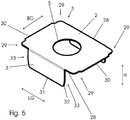
- FIG. 5 A particularly advantageous embodiment of the plug-in body 3 is shown in Figure 5 shown.
- This has a flat base body 2 with a length LG (shown by an arrow) of approx. 36 mm +/- 2 mm, a width BG (shown by an arrow) of approx. 26 mm +/- 2 mm and rounded corners 29 between the longitudinal side edges 28 and the broad side edges 30 with a radius of approximately 2 mm.
- This embodiment also has on the longitudinal side edges 28 arranged evenly in relation to the broad sides 30, flat insertable wings 3 with a width (extends in the direction of the length LG of the base body) of approx.
- the insert wings 3 are largely arranged at right angles to the base body 2.
- the side edges 32 of the insert wings 3 are beveled over a section 32 extending approximately 4 mm in length from the free end 31 in the direction of the base body 2 at an angle of 10 ° +/- 20. They also have a radius between the longitudinal edge of the free end 31 and the two side edges 32 (height direction) of approximately 1 mm.
- the plug-in body 3 also has a positioning recess 5, here a round hole.
- the diameter of the positioning recess 5 is approx. 13 mm +/- 2 mm. It is arranged in the center of the base body 2.
- the base body 2 and the insert wings 3 are formed in one piece.
- the plug-in body 2 is made as a bent shaped body, for example from a sheet metal approximately 0.5 mm +/- 0.2 mm thick.
- the plug-in body 3 could, for example, also consist of plastic or a composite material.
- Free end insert wing 11. Long hole 32. section 12. Positioning pin 33. Side edges 13th inside 14th Outside 15th Longitudinal edges 16.
- Spreader 17th Basic body construction rail 18th Free end 19th Profile leg 20th Bridges 21st Construction rail
Landscapes
- Engineering & Computer Science (AREA)
- Architecture (AREA)
- Civil Engineering (AREA)
- Structural Engineering (AREA)
- Physics & Mathematics (AREA)
- Acoustics & Sound (AREA)
- Building Environments (AREA)
- Finishing Walls (AREA)
Priority Applications (4)
| Application Number | Priority Date | Filing Date | Title |
|---|---|---|---|
| PL19157289T PL3696341T3 (pl) | 2019-02-14 | 2019-02-14 | Okładzina ścienna i sufitowa z paneli akustycznych |
| EP19157289.0A EP3696341B1 (fr) | 2019-02-14 | 2019-02-14 | Revêtement de mur et de plafond comprenant des panneaux acoustiques |
| ES19157289T ES2874662T3 (es) | 2019-02-14 | 2019-02-14 | Revestimiento de pared y techo que comprende paneles acústicos |
| PT191572890T PT3696341T (pt) | 2019-02-14 | 2019-02-14 | Revestimento de parede e de teto constituído por painéis acústicos |
Applications Claiming Priority (1)
| Application Number | Priority Date | Filing Date | Title |
|---|---|---|---|
| EP19157289.0A EP3696341B1 (fr) | 2019-02-14 | 2019-02-14 | Revêtement de mur et de plafond comprenant des panneaux acoustiques |
Publications (2)
| Publication Number | Publication Date |
|---|---|
| EP3696341A1 true EP3696341A1 (fr) | 2020-08-19 |
| EP3696341B1 EP3696341B1 (fr) | 2021-03-31 |
Family
ID=65440919
Family Applications (1)
| Application Number | Title | Priority Date | Filing Date |
|---|---|---|---|
| EP19157289.0A Active EP3696341B1 (fr) | 2019-02-14 | 2019-02-14 | Revêtement de mur et de plafond comprenant des panneaux acoustiques |
Country Status (4)
| Country | Link |
|---|---|
| EP (1) | EP3696341B1 (fr) |
| ES (1) | ES2874662T3 (fr) |
| PL (1) | PL3696341T3 (fr) |
| PT (1) | PT3696341T (fr) |
Cited By (1)
| Publication number | Priority date | Publication date | Assignee | Title |
|---|---|---|---|---|
| CN116357030A (zh) * | 2023-03-16 | 2023-06-30 | 陕西建工(安康)新型建材有限公司 | 一种岩板安装一体化预制构件及装配方法 |
Citations (5)
| Publication number | Priority date | Publication date | Assignee | Title |
|---|---|---|---|---|
| EP2003258A2 (fr) * | 2007-05-18 | 2008-12-17 | Plakabeton S.A. | Dispositif de fixation doté d'isolation acoustique à utiliser dans la construction d'immeubles |
| DE102009021904A1 (de) * | 2009-05-19 | 2010-12-30 | Michael Hanssen | Installationssystem zur Vorwandmontage, und Verfahren zur Herstellung |
| DE102014207852A1 (de) * | 2013-04-26 | 2014-10-30 | Holzwerke Ladenburger GmbH & Co. KG | Akustikabsorber-Bauelement |
| CN204001528U (zh) * | 2014-04-29 | 2014-12-10 | 张升锋 | 一种布艺吸声装置 |
| US20170044772A1 (en) * | 2015-08-12 | 2017-02-16 | Shraga Gestetner | Wall covering |
-
2019
- 2019-02-14 EP EP19157289.0A patent/EP3696341B1/fr active Active
- 2019-02-14 ES ES19157289T patent/ES2874662T3/es active Active
- 2019-02-14 PL PL19157289T patent/PL3696341T3/pl unknown
- 2019-02-14 PT PT191572890T patent/PT3696341T/pt unknown
Patent Citations (5)
| Publication number | Priority date | Publication date | Assignee | Title |
|---|---|---|---|---|
| EP2003258A2 (fr) * | 2007-05-18 | 2008-12-17 | Plakabeton S.A. | Dispositif de fixation doté d'isolation acoustique à utiliser dans la construction d'immeubles |
| DE102009021904A1 (de) * | 2009-05-19 | 2010-12-30 | Michael Hanssen | Installationssystem zur Vorwandmontage, und Verfahren zur Herstellung |
| DE102014207852A1 (de) * | 2013-04-26 | 2014-10-30 | Holzwerke Ladenburger GmbH & Co. KG | Akustikabsorber-Bauelement |
| CN204001528U (zh) * | 2014-04-29 | 2014-12-10 | 张升锋 | 一种布艺吸声装置 |
| US20170044772A1 (en) * | 2015-08-12 | 2017-02-16 | Shraga Gestetner | Wall covering |
Cited By (1)
| Publication number | Priority date | Publication date | Assignee | Title |
|---|---|---|---|---|
| CN116357030A (zh) * | 2023-03-16 | 2023-06-30 | 陕西建工(安康)新型建材有限公司 | 一种岩板安装一体化预制构件及装配方法 |
Also Published As
| Publication number | Publication date |
|---|---|
| PL3696341T3 (pl) | 2021-10-18 |
| ES2874662T3 (es) | 2021-11-05 |
| EP3696341B1 (fr) | 2021-03-31 |
| PT3696341T (pt) | 2021-06-09 |
Similar Documents
| Publication | Publication Date | Title |
|---|---|---|
| EP3321441B1 (fr) | Système de clip pour panneaux | |
| DE2908153C2 (fr) | ||
| DE202017102837U1 (de) | Paneele für ein dreidimensionales Dekor von Wand- und Deckenpaneelen | |
| DE69307916T2 (de) | Gipsplattenwand | |
| DE202021106266U1 (de) | Verbinder und ALC-Montageknotenstruktur | |
| DE102010051388B4 (de) | Verbindungsanordnung | |
| DE102013225173A1 (de) | Montageprofil für plattenförmige Module | |
| EP3696341B1 (fr) | Revêtement de mur et de plafond comprenant des panneaux acoustiques | |
| DE2610998B2 (de) | Halterung zur Befestigung von Bekleidungsplatten vor einer Bauwerkswand | |
| DE202017102839U1 (de) | Dreidimensionale Wand- oder Deckenverkleidung | |
| DE3239485A1 (de) | U-foermiges anschlussstueck fuer wandelemente | |
| DE2501330C3 (de) | Wand mit einem aus stabförmigen Bauelementen zusammengesetzten Traggerippe | |
| DE69610711T2 (de) | Stift- und gleitverfahren zur montage und befestigung einer verkleidung | |
| DE69923565T2 (de) | Verbindungsstruktur für vielfältige Teile | |
| EP1001103A2 (fr) | Profilé de bordure pour revêtement de mur | |
| EP0027196B1 (fr) | Structure de recouvrement avec dispositif de pinçage et élément de recouvrement | |
| EP1709887A2 (fr) | Garniture d'angle avec plinthes | |
| WO2020127770A1 (fr) | Attache de montage pour la fixation flottante de panneaux muraux et de plafond | |
| DE19730203A1 (de) | Überhangstreifen für ein Anschlußblech für Gebäude | |
| WO2008049540A1 (fr) | Système de fixation et procédé pour la fixation d'au moins un panneau par un bord et/ou par un coin | |
| DE202019103487U1 (de) | Spreizbarer Eckwinkel | |
| DE102012104000B4 (de) | Halter zur Fixierung eines Isolationskörpers an einer Pfosten- und Riegelanordnung und eine solche Pfosten- und Riegelanordnung | |
| DE19744340A1 (de) | Modulares Verkleidungssystem | |
| DE8516815U1 (de) | Befestigungselement | |
| EP1914358A2 (fr) | Moyen d'aide au montage |
Legal Events
| Date | Code | Title | Description |
|---|---|---|---|
| PUAI | Public reference made under article 153(3) epc to a published international application that has entered the european phase |
Free format text: ORIGINAL CODE: 0009012 |
|
| STAA | Information on the status of an ep patent application or granted ep patent |
Free format text: STATUS: REQUEST FOR EXAMINATION WAS MADE |
|
| 17P | Request for examination filed |
Effective date: 20191001 |
|
| AK | Designated contracting states |
Kind code of ref document: A1 Designated state(s): AL AT BE BG CH CY CZ DE DK EE ES FI FR GB GR HR HU IE IS IT LI LT LU LV MC MK MT NL NO PL PT RO RS SE SI SK SM TR |
|
| AX | Request for extension of the european patent |
Extension state: BA ME |
|
| GRAP | Despatch of communication of intention to grant a patent |
Free format text: ORIGINAL CODE: EPIDOSNIGR1 |
|
| STAA | Information on the status of an ep patent application or granted ep patent |
Free format text: STATUS: GRANT OF PATENT IS INTENDED |
|
| INTG | Intention to grant announced |
Effective date: 20201103 |
|
| GRAS | Grant fee paid |
Free format text: ORIGINAL CODE: EPIDOSNIGR3 |
|
| GRAA | (expected) grant |
Free format text: ORIGINAL CODE: 0009210 |
|
| STAA | Information on the status of an ep patent application or granted ep patent |
Free format text: STATUS: THE PATENT HAS BEEN GRANTED |
|
| AK | Designated contracting states |
Kind code of ref document: B1 Designated state(s): AL AT BE BG CH CY CZ DE DK EE ES FI FR GB GR HR HU IE IS IT LI LT LU LV MC MK MT NL NO PL PT RO RS SE SI SK SM TR |
|
| REG | Reference to a national code |
Ref country code: GB Ref legal event code: FG4D Free format text: NOT ENGLISH Ref country code: CH Ref legal event code: EP |
|
| REG | Reference to a national code |
Ref country code: DE Ref legal event code: R096 Ref document number: 502019001072 Country of ref document: DE Ref country code: AT Ref legal event code: REF Ref document number: 1377075 Country of ref document: AT Kind code of ref document: T Effective date: 20210415 |
|
| REG | Reference to a national code |
Ref country code: IE Ref legal event code: FG4D Free format text: LANGUAGE OF EP DOCUMENT: GERMAN |
|
| REG | Reference to a national code |
Ref country code: PT Ref legal event code: SC4A Ref document number: 3696341 Country of ref document: PT Date of ref document: 20210609 Kind code of ref document: T Free format text: AVAILABILITY OF NATIONAL TRANSLATION Effective date: 20210604 |
|
| REG | Reference to a national code |
Ref country code: NL Ref legal event code: FP |
|
| REG | Reference to a national code |
Ref country code: SE Ref legal event code: TRGR |
|
| REG | Reference to a national code |
Ref country code: LT Ref legal event code: MG9D |
|
| PG25 | Lapsed in a contracting state [announced via postgrant information from national office to epo] |
Ref country code: NO Free format text: LAPSE BECAUSE OF FAILURE TO SUBMIT A TRANSLATION OF THE DESCRIPTION OR TO PAY THE FEE WITHIN THE PRESCRIBED TIME-LIMIT Effective date: 20210630 Ref country code: BG Free format text: LAPSE BECAUSE OF FAILURE TO SUBMIT A TRANSLATION OF THE DESCRIPTION OR TO PAY THE FEE WITHIN THE PRESCRIBED TIME-LIMIT Effective date: 20210630 Ref country code: FI Free format text: LAPSE BECAUSE OF FAILURE TO SUBMIT A TRANSLATION OF THE DESCRIPTION OR TO PAY THE FEE WITHIN THE PRESCRIBED TIME-LIMIT Effective date: 20210331 Ref country code: HR Free format text: LAPSE BECAUSE OF FAILURE TO SUBMIT A TRANSLATION OF THE DESCRIPTION OR TO PAY THE FEE WITHIN THE PRESCRIBED TIME-LIMIT Effective date: 20210331 |
|
| PG25 | Lapsed in a contracting state [announced via postgrant information from national office to epo] |
Ref country code: LV Free format text: LAPSE BECAUSE OF FAILURE TO SUBMIT A TRANSLATION OF THE DESCRIPTION OR TO PAY THE FEE WITHIN THE PRESCRIBED TIME-LIMIT Effective date: 20210331 Ref country code: RS Free format text: LAPSE BECAUSE OF FAILURE TO SUBMIT A TRANSLATION OF THE DESCRIPTION OR TO PAY THE FEE WITHIN THE PRESCRIBED TIME-LIMIT Effective date: 20210331 |
|
| PG25 | Lapsed in a contracting state [announced via postgrant information from national office to epo] |
Ref country code: SM Free format text: LAPSE BECAUSE OF FAILURE TO SUBMIT A TRANSLATION OF THE DESCRIPTION OR TO PAY THE FEE WITHIN THE PRESCRIBED TIME-LIMIT Effective date: 20210331 Ref country code: EE Free format text: LAPSE BECAUSE OF FAILURE TO SUBMIT A TRANSLATION OF THE DESCRIPTION OR TO PAY THE FEE WITHIN THE PRESCRIBED TIME-LIMIT Effective date: 20210331 Ref country code: CZ Free format text: LAPSE BECAUSE OF FAILURE TO SUBMIT A TRANSLATION OF THE DESCRIPTION OR TO PAY THE FEE WITHIN THE PRESCRIBED TIME-LIMIT Effective date: 20210331 Ref country code: LT Free format text: LAPSE BECAUSE OF FAILURE TO SUBMIT A TRANSLATION OF THE DESCRIPTION OR TO PAY THE FEE WITHIN THE PRESCRIBED TIME-LIMIT Effective date: 20210331 |
|
| REG | Reference to a national code |
Ref country code: ES Ref legal event code: FG2A Ref document number: 2874662 Country of ref document: ES Kind code of ref document: T3 Effective date: 20211105 |
|
| PG25 | Lapsed in a contracting state [announced via postgrant information from national office to epo] |
Ref country code: SK Free format text: LAPSE BECAUSE OF FAILURE TO SUBMIT A TRANSLATION OF THE DESCRIPTION OR TO PAY THE FEE WITHIN THE PRESCRIBED TIME-LIMIT Effective date: 20210331 Ref country code: RO Free format text: LAPSE BECAUSE OF FAILURE TO SUBMIT A TRANSLATION OF THE DESCRIPTION OR TO PAY THE FEE WITHIN THE PRESCRIBED TIME-LIMIT Effective date: 20210331 Ref country code: IS Free format text: LAPSE BECAUSE OF FAILURE TO SUBMIT A TRANSLATION OF THE DESCRIPTION OR TO PAY THE FEE WITHIN THE PRESCRIBED TIME-LIMIT Effective date: 20210731 |
|
| REG | Reference to a national code |
Ref country code: DE Ref legal event code: R097 Ref document number: 502019001072 Country of ref document: DE |
|
| PG25 | Lapsed in a contracting state [announced via postgrant information from national office to epo] |
Ref country code: DK Free format text: LAPSE BECAUSE OF FAILURE TO SUBMIT A TRANSLATION OF THE DESCRIPTION OR TO PAY THE FEE WITHIN THE PRESCRIBED TIME-LIMIT Effective date: 20210331 Ref country code: AL Free format text: LAPSE BECAUSE OF FAILURE TO SUBMIT A TRANSLATION OF THE DESCRIPTION OR TO PAY THE FEE WITHIN THE PRESCRIBED TIME-LIMIT Effective date: 20210331 |
|
| PLBE | No opposition filed within time limit |
Free format text: ORIGINAL CODE: 0009261 |
|
| STAA | Information on the status of an ep patent application or granted ep patent |
Free format text: STATUS: NO OPPOSITION FILED WITHIN TIME LIMIT |
|
| 26N | No opposition filed |
Effective date: 20220104 |
|
| PG25 | Lapsed in a contracting state [announced via postgrant information from national office to epo] |
Ref country code: IS Free format text: LAPSE BECAUSE OF FAILURE TO SUBMIT A TRANSLATION OF THE DESCRIPTION OR TO PAY THE FEE WITHIN THE PRESCRIBED TIME-LIMIT Effective date: 20210731 |
|
| PG25 | Lapsed in a contracting state [announced via postgrant information from national office to epo] |
Ref country code: MC Free format text: LAPSE BECAUSE OF FAILURE TO SUBMIT A TRANSLATION OF THE DESCRIPTION OR TO PAY THE FEE WITHIN THE PRESCRIBED TIME-LIMIT Effective date: 20210331 |
|
| PG25 | Lapsed in a contracting state [announced via postgrant information from national office to epo] |
Ref country code: LU Free format text: LAPSE BECAUSE OF NON-PAYMENT OF DUE FEES Effective date: 20220214 |
|
| PG25 | Lapsed in a contracting state [announced via postgrant information from national office to epo] |
Ref country code: IE Free format text: LAPSE BECAUSE OF NON-PAYMENT OF DUE FEES Effective date: 20220214 |
|
| PGFP | Annual fee paid to national office [announced via postgrant information from national office to epo] |
Ref country code: NL Payment date: 20230220 Year of fee payment: 5 |
|
| PGFP | Annual fee paid to national office [announced via postgrant information from national office to epo] |
Ref country code: ES Payment date: 20230317 Year of fee payment: 5 |
|
| PGFP | Annual fee paid to national office [announced via postgrant information from national office to epo] |
Ref country code: TR Payment date: 20230209 Year of fee payment: 5 Ref country code: SE Payment date: 20230220 Year of fee payment: 5 Ref country code: PT Payment date: 20230202 Year of fee payment: 5 Ref country code: PL Payment date: 20230131 Year of fee payment: 5 Ref country code: IT Payment date: 20230228 Year of fee payment: 5 Ref country code: BE Payment date: 20230220 Year of fee payment: 5 |
|
| PG25 | Lapsed in a contracting state [announced via postgrant information from national office to epo] |
Ref country code: MK Free format text: LAPSE BECAUSE OF FAILURE TO SUBMIT A TRANSLATION OF THE DESCRIPTION OR TO PAY THE FEE WITHIN THE PRESCRIBED TIME-LIMIT Effective date: 20210331 Ref country code: CY Free format text: LAPSE BECAUSE OF FAILURE TO SUBMIT A TRANSLATION OF THE DESCRIPTION OR TO PAY THE FEE WITHIN THE PRESCRIBED TIME-LIMIT Effective date: 20210331 |
|
| PG25 | Lapsed in a contracting state [announced via postgrant information from national office to epo] |
Ref country code: HU Free format text: LAPSE BECAUSE OF FAILURE TO SUBMIT A TRANSLATION OF THE DESCRIPTION OR TO PAY THE FEE WITHIN THE PRESCRIBED TIME-LIMIT; INVALID AB INITIO Effective date: 20190214 |
|
| PG25 | Lapsed in a contracting state [announced via postgrant information from national office to epo] |
Ref country code: MT Free format text: LAPSE BECAUSE OF FAILURE TO SUBMIT A TRANSLATION OF THE DESCRIPTION OR TO PAY THE FEE WITHIN THE PRESCRIBED TIME-LIMIT Effective date: 20210331 |
|
| REG | Reference to a national code |
Ref country code: SE Ref legal event code: EUG |
|
| REG | Reference to a national code |
Ref country code: NL Ref legal event code: MM Effective date: 20240301 |
|
| PG25 | Lapsed in a contracting state [announced via postgrant information from national office to epo] |
Ref country code: PT Free format text: LAPSE BECAUSE OF NON-PAYMENT OF DUE FEES Effective date: 20240814 |
|
| PG25 | Lapsed in a contracting state [announced via postgrant information from national office to epo] |
Ref country code: PT Free format text: LAPSE BECAUSE OF NON-PAYMENT OF DUE FEES Effective date: 20240814 |
|
| PG25 | Lapsed in a contracting state [announced via postgrant information from national office to epo] |
Ref country code: NL Free format text: LAPSE BECAUSE OF NON-PAYMENT OF DUE FEES Effective date: 20240301 |
|
| PG25 | Lapsed in a contracting state [announced via postgrant information from national office to epo] |
Ref country code: NL Free format text: LAPSE BECAUSE OF NON-PAYMENT OF DUE FEES Effective date: 20240301 |
|
| REG | Reference to a national code |
Ref country code: BE Ref legal event code: MM Effective date: 20240229 |
|
| PG25 | Lapsed in a contracting state [announced via postgrant information from national office to epo] |
Ref country code: GR Free format text: LAPSE BECAUSE OF NON-PAYMENT OF DUE FEES Effective date: 20210331 |
|
| PG25 | Lapsed in a contracting state [announced via postgrant information from national office to epo] |
Ref country code: GR Free format text: LAPSE BECAUSE OF NON-PAYMENT OF DUE FEES Effective date: 20210331 |
|
| PG25 | Lapsed in a contracting state [announced via postgrant information from national office to epo] |
Ref country code: BE Free format text: LAPSE BECAUSE OF NON-PAYMENT OF DUE FEES Effective date: 20240229 |
|
| PG25 | Lapsed in a contracting state [announced via postgrant information from national office to epo] |
Ref country code: BE Free format text: LAPSE BECAUSE OF NON-PAYMENT OF DUE FEES Effective date: 20240229 |
|
| PG25 | Lapsed in a contracting state [announced via postgrant information from national office to epo] |
Ref country code: IT Free format text: LAPSE BECAUSE OF NON-PAYMENT OF DUE FEES Effective date: 20240214 |
|
| REG | Reference to a national code |
Ref country code: ES Ref legal event code: FD2A Effective date: 20250327 |
|
| PG25 | Lapsed in a contracting state [announced via postgrant information from national office to epo] |
Ref country code: ES Free format text: LAPSE BECAUSE OF NON-PAYMENT OF DUE FEES Effective date: 20240215 |
|
| PG25 | Lapsed in a contracting state [announced via postgrant information from national office to epo] |
Ref country code: SE Free format text: LAPSE BECAUSE OF NON-PAYMENT OF DUE FEES Effective date: 20240215 |
|
| PG25 | Lapsed in a contracting state [announced via postgrant information from national office to epo] |
Ref country code: PL Free format text: LAPSE BECAUSE OF NON-PAYMENT OF DUE FEES Effective date: 20240214 |
|
| REG | Reference to a national code |
Ref country code: CH Ref legal event code: U11 Free format text: ST27 STATUS EVENT CODE: U-0-0-U10-U11 (AS PROVIDED BY THE NATIONAL OFFICE) Effective date: 20260301 |
|
| PGFP | Annual fee paid to national office [announced via postgrant information from national office to epo] |
Ref country code: GB Payment date: 20260219 Year of fee payment: 8 |
|
| PGFP | Annual fee paid to national office [announced via postgrant information from national office to epo] |
Ref country code: DE Payment date: 20260223 Year of fee payment: 8 |
|
| PGFP | Annual fee paid to national office [announced via postgrant information from national office to epo] |
Ref country code: AT Payment date: 20260216 Year of fee payment: 8 |
|
| PGFP | Annual fee paid to national office [announced via postgrant information from national office to epo] |
Ref country code: FR Payment date: 20260223 Year of fee payment: 8 |
|
| PGFP | Annual fee paid to national office [announced via postgrant information from national office to epo] |
Ref country code: CH Payment date: 20260301 Year of fee payment: 8 |