EP3696362A1 - Dispositif de support d'éléments de fenêtre ou de porte - Google Patents
Dispositif de support d'éléments de fenêtre ou de porte Download PDFInfo
- Publication number
- EP3696362A1 EP3696362A1 EP20157435.7A EP20157435A EP3696362A1 EP 3696362 A1 EP3696362 A1 EP 3696362A1 EP 20157435 A EP20157435 A EP 20157435A EP 3696362 A1 EP3696362 A1 EP 3696362A1
- Authority
- EP
- European Patent Office
- Prior art keywords
- profile
- profile rail
- support element
- longitudinal end
- leg
- Prior art date
- Legal status (The legal status is an assumption and is not a legal conclusion. Google has not performed a legal analysis and makes no representation as to the accuracy of the status listed.)
- Granted
Links
Images


Classifications
-
- E—FIXED CONSTRUCTIONS
- E06—DOORS, WINDOWS, SHUTTERS, OR ROLLER BLINDS IN GENERAL; LADDERS
- E06B—FIXED OR MOVABLE CLOSURES FOR OPENINGS IN BUILDINGS, VEHICLES, FENCES OR LIKE ENCLOSURES IN GENERAL, e.g. DOORS, WINDOWS, BLINDS, GATES
- E06B1/00—Border constructions of openings in walls, floors, or ceilings; Frames to be rigidly mounted in such openings
- E06B1/56—Fastening frames to the border of openings or to similar contiguous frames
- E06B1/60—Fastening frames to the border of openings or to similar contiguous frames by mechanical means, e.g. anchoring means
- E06B1/6015—Anchoring means
- E06B1/6023—Anchoring means completely hidden between the frame and the border of the opening, at least part of the means being previously fixed to the wall
-
- E—FIXED CONSTRUCTIONS
- E06—DOORS, WINDOWS, SHUTTERS, OR ROLLER BLINDS IN GENERAL; LADDERS
- E06B—FIXED OR MOVABLE CLOSURES FOR OPENINGS IN BUILDINGS, VEHICLES, FENCES OR LIKE ENCLOSURES IN GENERAL, e.g. DOORS, WINDOWS, BLINDS, GATES
- E06B1/00—Border constructions of openings in walls, floors, or ceilings; Frames to be rigidly mounted in such openings
- E06B1/003—Cavity wall closers; Fastening door or window frames in cavity walls
Definitions
- window and door frames are an important task in modern multi-shell building envelopes, especially because a modern building envelope consists of a large number of functional materials of different thicknesses, strengths and resilience.
- a frame is placed in an area of the building envelope that is sensible in terms of energy technology or specified by building regulations, but which does not have to be identical to a load-bearing wall section.
- plate elements made of wood were previously placed at least at the lower limit of a wall opening and screwed to both the frame and the building envelope.
- assembly devices are often used that have both holding and adjusting elements.
- these are devices such as profile rails, in which a threaded rod is attached at right angles to one end.
- the threaded rod can in turn receive support plates or brackets that are adjustable along the longitudinal axis of the thread. This makes it possible to fasten it in a wall opening, usually on the reveal or parapet, but also to adjust the position of the component in three dimensions.
- Such adjustment elements are not favorable because of the additional functionality.
- the setting options for threaded elements are sensitive, but they also make it time-consuming.
- the utility model DE20 2011 108 043 shows a device for fixing a frame in a wall opening below. It recommends a combination of a profile rail with a mounting bracket, the legs of which have a plurality of holes. One of the legs is screwed to the profile rail, the other to the frame. The height adjustment of the frame in relation to the profile rail is carried out using blocks.
- the object of the present invention is to offer a system that is less complex than the prior art, which can be used with little effort, requires little adjustment effort on the construction site and can be produced efficiently.
- the device comprises at least one support element 10 and a rigid profile rail 20, 36 or 60.
- the support element 10 has an upper side 13 and a lower side 14; the terms above and below refer to the intended installation position at the bottom of the opening, on the parapet.
- the profile rail has a first longitudinal end 21 and a second longitudinal end 22; on, top and bottom are designated with the reference numerals 18 and 19 in a logic analogous to that of the support element. "Above" on the profile rail therefore corresponds to "above” on the support element if both are installed properly.
- the bottom of the profile rail faces the parapet (wall side), the top faces the window or door element to be installed.
- the first longitudinal end of the profile rail has openings for receiving fasteners.
- the openings are not necessarily arranged exclusively on the edge.
- Fasteners primarily mean screws including their variants and technical equivalents, which a specialist selects depending on the structure of the building wall, the floor, the weight of the window or Door elements or according to the requirements of statics, fire protection or a thermal insulation ordinance.
- openings are through bores, threaded holes or others, e.g. by embossing intended positions in which the setting of a fastener is possible. Shape and dimensions depend on the intended use (holes, elongated holes, etc.).
- the first longitudinal end is provided for fastening the profile rail to the parapet (on the reveal or on the floor), the second longitudinal end is used to accommodate the support element.
- a profile with ribs, bolts, depressions and / or pins is introduced at the second longitudinal end on the upper side. These can form a symmetrical or deliberately asymmetrical pattern.
- the named profile elements are used to define a specific positional relationship between the profile rail and support element.
- the top of the support element is flat like a table and the bottom has a complementary mating profile to the profile.
- This mating profile is designed in such a way that it forms a form fit with the profile at the second longitudinal end of the profile rail when the two elements are connected as intended.
- the profile rail has one or more longitudinal ribs
- the counter profile would be designed as corresponding grooves.
- the profile 26 consists of raised pins
- the counter profile would consist of holes or depressions into which the pins can engage.
- the profile rail and support element have elements that can interlock in a form-fitting manner.
- the device is preferably developed in such a way that the second longitudinal end of the profile rail has at least one receiving opening for (at least) one clamping element.
- This clamping element is provided accordingly on the support element.
- the connection is secured by the interlocking of the clamping element and the receiving opening.
- the clamping element on the support element can be wedge-shaped or conical and engages in the through-hole (receiving opening 17 in the profile rail) when it is (positively) fitted together and is held there by a friction fit.
- the clamping element can be designed as a tubular, longitudinally slotted sleeve. These sleeve segments can thus act as spring elements and, in conjunction with known retaining tongues, can be used as latching elements that can cause the receiving element and the profile rail to be locked.
- the profile rail addressed in the present invention can have a C, W, U, double-T cross-sectional profile, as is known from the prior art.
- the profile rail is designed as a tubular profile and has at least two opposing, flat, extended and parallel surfaces. The design described here in the basics would be a tube with a parallel flattened length.
- the profile rail is designed with a (essentially) rectangular cross-sectional profile, in particular as an essentially rectangular hollow cross-sectional profile.
- the rectangular cross-sectional profile can include further stiffening features, as in FIG Figure 3b shown.
- the rectangular-tubular cross-sectional profile / hollow cross-sectional profile allows a significantly better load-bearing capacity than a more rigid, simpler flat iron. Without running counter to this aim, cutouts, through-holes or recesses can be provided in the profile rail, depending on how the intended use requires.
- the statement "has a cross-sectional profile” is to be understood with the addition “over substantial parts of the total length”.
- the profile rail is preferably made predominantly of metal, in particular of steel.
- the profile rail can be provided with protective coatings made of zinc, lacquer or passivation processes or made of stainless steel.
- the manufacturing processes for steel profiles are well known. Hollow profiles of the type described above can be bent from flat metal strips or plates and longitudinally welded or formed from round tubes.
- the support element can also be made of metal (e.g. zinc die-cast, aluminum die-cast), but preferably of plastic, in particular of thermoplastic by injection molding, compression molding or the like. In this way, the profile described above can also be easily implemented in plastic.
- the underside of the support element can also have other features that serve to reinforce the support element. It is also possible to supplement those profile elements that allow the form fit with means that cause a clamping or locking with the profile rail. Improved handling can thereby be achieved.
- the surface of the upper side of the support element is preferably designed to be larger than its contact surface with the profile rail, in short, it protrudes on the sides. Due to the interlocking of profile / counter profile and the described design with a clamping element A widened support platform for the window or door frame is created at the second longitudinal end during assembly.
- the mating profile is preferably designed in such a way that it allows a form fit with the profile rail in exactly one position. This increases the application security because it helps prevent incorrect assembly.
- the clamping element especially when designed as a latching element, gives the user clear feedback when joining the profile rail and support element.
- the support element and profile rail are designed in such a way that the top of the support element is flush with the top side of the profile rail (reference 18, 32) in the positively connected state. This creates a continuous surface which, when assembling a door or window component, allows it to be moved without any steps.
- an assembly process will proceed in such a way that a fitter joins a support element and a profile rail and automatically secures it by means of the clamping element.
- the profile rail is attached to the parapet (soffit or on the floor) of a building opening according to the specifications of an installation or assembly plan.
- Fasteners such as screws that use the holes provided in the profile rail are usually used for this purpose. These can have different diameters and / or be designed as elongated holes.
- the second end of the profile rail with attached support element is arranged in the area of the building opening where the window or door element is to be located. After one or more such combinations have been attached to the parapet (or the floor), the window or door element can be lifted into place. Due to the (surface) flush transition between the profile rail and the support element, an imprecise initial setting is not critical, the window element can then be pushed into position without any problems.
- the support element according to the invention provides the fitter with a widened, flat working surface for fine adjustment.
- the window element does not rest on narrow webs or the profile rail itself, but on a surface that is flush with the profile rail. Should it be necessary to adjust the height using spacer blocks, it is also easier to provide or adjust them.
- This angle element has a first and a second leg arranged at right angles to one another.
- the task of the angle element is the mechanical connection of the profile rail and window or door element. It serves less to transfer the load of its own weight than to transfer dynamic loads such as pressure and suction from wind.
- the second leg has for this purpose two beveled edge guides arranged in parallel, the spacing of which essentially corresponds to the width of the profile rail on its upper side. These edge guides, which can be produced by folding the longitudinal edges of the second leg, act as a lateral guide when the bracket is placed on the profile rail.
- the first leg of the angle element is designed to be connected to the door or window component. As is known, this can be done with screws or self-tapping screws or, technically equivalent, with riveting, gluing or other connection techniques.
- the first leg can be provided with a plurality of bores. With bores, through bores, through openings or also blind holes can be meant, which merely represent guide aids for a fastener. The plurality of holes allows the fitter to select the best position for the fastener or fasteners for the application.
- the fastening of the second leg which rests on the profile rail as intended, can be carried out by precisely one screw which is inserted into the surface of the second leg facing the interior.
- This definition appears astonishing at first glance, since it deprives the fitter of a degree of freedom.
- this reduction to a target position allows the position that is optimized in terms of load transfer technology to be selected. Since the profile rail can have a (transverse) profile, this prevents a fitter from choosing an unfavorable location for the fastener.
- This specification of the position is achieved in that the second leg is provided with exactly one hole. What was said above applies analogously to the meaning of the term borehole.
- this individual bore is made eccentrically in the end area of the second leg facing away from the angle apex.
- the end area will preferably comprise a third of the leg length, and the eccentric position is chosen closer to the leg edge than in the middle.
- the angle element is used after the window element has been lifted and aligned in its desired position on the support element relative to the building opening.
- the angle element is placed with its second leg and is inevitably aligned by the edge guides surrounding the profile rail on the side. By sliding along the profile rail, the angle element is moved in the direction of the window element until the first leg hits the frame.
- Its leg length is chosen so that it ensures the necessary load dissipation, but does not impair the visual appearance of the window element.
- angle elements with different lengths of the first leg can be provided, while the second leg length (except for special designs) can be chosen the same for all variants.
- the arrangement of profile rail 20, 60, support element 10 and an angle element 40, 50 can be viewed in a second design.
- the angle element has a first and a second leg arranged at right angles to one another.
- the second leg has two parallel, beveled, edge guides pointing away from the interior of the angle, the clear spacing of which essentially corresponds to the width of the profile rail on its upper side.
- the beveled edge guides are therefore designed as flat guide webs which, in the assembled state, are arranged parallel to the side surfaces of the profile rail.
- the orientation is meant as described at the beginning.
- the folded edge guides have at least one opening (bore, through-hole, embossing), preferably at least one opening per edge guide.
- the surface of the second leg facing the interior can do without bores or through openings.
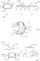
- Figure 1 shows a support element 10 according to the invention, in Figure 1a ) from the profiled underside 14 shown.
- Point 28 marked with an oval denotes the counter profile.
- the marked area does not designate the size of the area provided with the profile 28 but only a region thereof.
- the size and shape depend on the profile rail 20 and how much (in terms of area) the support element 10 is larger than an end region of a profile rail.
- the drawing shows a pattern of profile elements, ribs or stiffeners.
- the feature 29 denotes a longitudinal stop which serves as a receptacle for the longitudinal end 22 of the profile rail 20.
- Feature 12 marks the clamping element 12. In the side view of FIG Figure 1b ) this clamping element is recognizable as a pin-shaped or sleeve-shaped element.
- the upper side 13 is designed flat and table-like, whereas the lower side 14 has the profiling which allows the form fit with a longitudinal end 22 of the profile rail.
- Figure 2 shows a profile rail 20 according to the invention in 3 views (from top to bottom: top, side view, bottom).
- the first longitudinal end 21 is shown on the right, the second longitudinal end 22 on the left.
- the embodiment shown has a hollow cross-sectional profile and is partially open, that is to say cut open.
- the left (second) longitudinal end 22 has the profile 26. It was created by removing the top surface of the profile rail 20 in the end area; the profile therefore consists in this form (essentially) of two longitudinal webs and the receiving opening 17 for the clamping element 12. In the side view of Figure 2b ) it becomes clear that this creates a paragraph 31. At this point - after joining with a support element 10 - the profile rail passes over flush with the support element.
- the upper side 18 has further special features at the opposite, first longitudinal end 21. Here, several openings 23, 24, 25 are shown as examples, holes 23, 24 and elongated hole 25.
- the openings on the top 18 are partially oversized so that a screw head can penetrate the top and only then on the material of the underside is supported. This explains why the same openings 24, 25 on the underside 19 (cf. Figure 2c ) are shown smaller.
- Figure 1 shows one side of the support element 10 with counter profile 28 and longitudinal or transverse reinforcement elements. A longitudinal stop 29 is also shown, up to which the support element 10 can be pushed onto the profile rail 20.
- Figure 3a shows a tubular profile 30 'with two parallel, flat contact surfaces (surfaces) 32, 34 and side surfaces 37, 38.
- Figure 3b a variant 30 is shown as a rectangular hollow profile 36.
- the longitudinal profiling which leads to a further increase in the rigidity of the profile rail 20, is also clearly visible here.
- Figure 3c shows a profile rail 60 according to the prior art with a longitudinal reinforcement as in the hollow profile 36 of Figure 3b ).
- the synopsis of Figure 2a ) The longitudinal end 22 and the profile rail 60 makes it clear that the resulting profile 26, after removing a section of the top 18 from the rectangular hollow profile 36, resembles the classic profile of the profile rail 60. This opens up the possibility of using the support element 10 also with a classic profile rail 60, provided that a receiving opening 17 for the clamping element 12 is also provided in it.
- Figure 4 shows the angle element 40 in an oblique plan view.
- the first leg 41 intended to stop a window or door element, has a plurality of bores 43, 43 ', 43 ", ...
- the arrangement and diameter of the bores / openings is not mandatory, but is shown as an example.
- the second leg 42 of the angle element 40 is intended to rest on the top side 18/32 of a profile rail 20 or an angle profile 60 according to the prior art.
- the edge guides 45 and 46 encompass the upper side 18/32/60 and ensure handling safety.
- the individual bore 44 in the second leg 42 can be seen.
- FIG Figure 5 shown is a side view of the angle with the visible fold / edge guide 45 on the second leg 42.
- Figure 5b shows a plan view of the first leg 41 in a shortened variant compared to FIG Figure 4.
- Figure 5c shows a top view of the second leg 42 with the edge guides 45, 46 and the individual bore in the second leg.
- Figure 6 shows a support angle (angle element) 50 as a further improved version of the angle 40 Figure 4 .
- a second leg 54 is designed to be placed on a profile rail 20 or 60. For this purpose, it has guide edges or webs in the form of beveled edge guides 51, 53, which support an alignment / edge guide on the profile rail 20, 30 and 60, respectively.
- a first leg 52 is arranged essentially at right angles to the first leg 52.
- First and second legs 52, 54 enclose the interior of the angle between them.
- a plurality of openings allows the fitter to set one or more fasteners depending on the window or door element and to make the connection as intended or prescribed.
- the second leg 54 is designed such that the guide webs or edge guides 51, 53 provided laterally in the longitudinal extension of the angled leg encompass the profile rail 60, as in FIG Figure 7 shown.
- the clear space or the clear distance between the two lateral guide webs 51, 53 is selected so that the angle element is guided on the profile rail 60 with little play and remains longitudinally displaceable for adjustment.
- the guide webs 51, 53 each have at least one opening 58, preferably a through-hole, while the surface of the second leg 54 facing the interior manages without holes / through-openings.
- the opening 58 serves as a guide for a fastener which can connect the angle element 50 to the profile rail 60 in a non-positive manner. This can be done either from the left or the right, as defined above in the arrangement logic.
- the angle element 40 from Figure 4 uses the bore 44 for fastening to a profile rail, through which a fastener can be passed. Forces on the angle 40 can lead to a tipping load an axis which is at the apex of the angle 40. As a result, a fastener that has been placed in a profile rail through the bore 44 is subjected to tensile load and the thread must transfer this force to the profile rail.
- FIG. 7 an installation situation is shown with a profile rail 60 which is screwed at its first longitudinal end 21 through an opening 23 on the inner surface of a parapet 59.
- a support element 10 is attached to the second longitudinal end of the profile rail 60; its top is flush with the upper longitudinal edges (guide webs 51, 53) of the profile rail 60 (cf. Figure 3c ) from.
- An angle element 50 is placed on the profile rail in such a way that its guide webs 51, 53 come to lie parallel to the side surfaces 37, 38 of the profile rail 60.
- a fastener 57 uses the opening 58 to connect the angle element 50 to the profile rail.
- a window element (not shown) would be placed on the support element and screwed in a height-adjusted manner to the other leg of the bracket in the desired position.
Landscapes
- Engineering & Computer Science (AREA)
- Civil Engineering (AREA)
- Structural Engineering (AREA)
- Mechanical Engineering (AREA)
- Support Devices For Sliding Doors (AREA)
Priority Applications (1)
| Application Number | Priority Date | Filing Date | Title |
|---|---|---|---|
| PL20157435T PL3696362T3 (pl) | 2019-02-15 | 2020-02-14 | Urządzenie do podpierania elementów okiennych lub drzwiowych |
Applications Claiming Priority (1)
| Application Number | Priority Date | Filing Date | Title |
|---|---|---|---|
| EP19157329.4A EP3696361B8 (fr) | 2019-02-15 | 2019-02-15 | Dispositif de support d'éléments de fenêtre ou de porte |
Publications (3)
| Publication Number | Publication Date |
|---|---|
| EP3696362A1 true EP3696362A1 (fr) | 2020-08-19 |
| EP3696362B1 EP3696362B1 (fr) | 2022-03-30 |
| EP3696362B8 EP3696362B8 (fr) | 2022-05-04 |
Family
ID=65443691
Family Applications (2)
| Application Number | Title | Priority Date | Filing Date |
|---|---|---|---|
| EP19157329.4A Active EP3696361B8 (fr) | 2019-02-15 | 2019-02-15 | Dispositif de support d'éléments de fenêtre ou de porte |
| EP20157435.7A Active EP3696362B8 (fr) | 2019-02-15 | 2020-02-14 | Dispositif de support d'éléments de fenêtre ou de porte |
Family Applications Before (1)
| Application Number | Title | Priority Date | Filing Date |
|---|---|---|---|
| EP19157329.4A Active EP3696361B8 (fr) | 2019-02-15 | 2019-02-15 | Dispositif de support d'éléments de fenêtre ou de porte |
Country Status (2)
| Country | Link |
|---|---|
| EP (2) | EP3696361B8 (fr) |
| PL (2) | PL3696361T3 (fr) |
Citations (8)
| Publication number | Priority date | Publication date | Assignee | Title |
|---|---|---|---|---|
| EP0945577A2 (fr) | 1998-03-23 | 1999-09-29 | SFS Industrie Holding AG | Dispositif de support d'encadrements pour portes ou fenêtres à la périphérie d'une ouverture de paroi |
| EP1500767A2 (fr) | 2003-07-25 | 2005-01-26 | SFS intec Holding AG | Dispositif de support et de fixation d'encadrements pour portes ou fenêtres à la périphérie d'une ouverture de paroi |
| KR100899787B1 (ko) * | 2008-11-18 | 2009-05-28 | 데카코리아(주) | 고정브래킷 |
| KR20100001682U (ko) * | 2008-08-06 | 2010-02-17 | 김명근 | 창호 설치용 결속구 및 이 결속구에 설치되는 창틀간격조절구 |
| DE202011108043U1 (de) | 2011-11-18 | 2012-01-12 | Knelsen Gmbh | Vorrichtung zum Fixieren eines Baukörpers in einer Gebäudeöffnung |
| FR2966211A1 (fr) * | 2010-10-15 | 2012-04-20 | Tordo Belgrano Sa | Equerre de fixation et mode de pose |
| EP2896774A1 (fr) * | 2014-01-20 | 2015-07-22 | Knelsen GmbH | Dispositif de fixation d'un corps de construction |
| KR101583352B1 (ko) * | 2015-06-22 | 2016-01-19 | 주식회사 대진테크 | 창틀 고정용 브라켓 |
-
2019
- 2019-02-15 EP EP19157329.4A patent/EP3696361B8/fr active Active
- 2019-02-15 PL PL19157329.4T patent/PL3696361T3/pl unknown
-
2020
- 2020-02-14 PL PL20157435T patent/PL3696362T3/pl unknown
- 2020-02-14 EP EP20157435.7A patent/EP3696362B8/fr active Active
Patent Citations (8)
| Publication number | Priority date | Publication date | Assignee | Title |
|---|---|---|---|---|
| EP0945577A2 (fr) | 1998-03-23 | 1999-09-29 | SFS Industrie Holding AG | Dispositif de support d'encadrements pour portes ou fenêtres à la périphérie d'une ouverture de paroi |
| EP1500767A2 (fr) | 2003-07-25 | 2005-01-26 | SFS intec Holding AG | Dispositif de support et de fixation d'encadrements pour portes ou fenêtres à la périphérie d'une ouverture de paroi |
| KR20100001682U (ko) * | 2008-08-06 | 2010-02-17 | 김명근 | 창호 설치용 결속구 및 이 결속구에 설치되는 창틀간격조절구 |
| KR100899787B1 (ko) * | 2008-11-18 | 2009-05-28 | 데카코리아(주) | 고정브래킷 |
| FR2966211A1 (fr) * | 2010-10-15 | 2012-04-20 | Tordo Belgrano Sa | Equerre de fixation et mode de pose |
| DE202011108043U1 (de) | 2011-11-18 | 2012-01-12 | Knelsen Gmbh | Vorrichtung zum Fixieren eines Baukörpers in einer Gebäudeöffnung |
| EP2896774A1 (fr) * | 2014-01-20 | 2015-07-22 | Knelsen GmbH | Dispositif de fixation d'un corps de construction |
| KR101583352B1 (ko) * | 2015-06-22 | 2016-01-19 | 주식회사 대진테크 | 창틀 고정용 브라켓 |
Also Published As
| Publication number | Publication date |
|---|---|
| EP3696362B1 (fr) | 2022-03-30 |
| PL3696361T3 (pl) | 2022-07-25 |
| EP3696361A1 (fr) | 2020-08-19 |
| EP3696362B8 (fr) | 2022-05-04 |
| EP3696361B1 (fr) | 2022-03-30 |
| EP3696361B8 (fr) | 2022-05-04 |
| PL3696362T3 (pl) | 2022-06-20 |
Similar Documents
| Publication | Publication Date | Title |
|---|---|---|
| EP2186966B1 (fr) | Structure de façades | |
| EP0945577A2 (fr) | Dispositif de support d'encadrements pour portes ou fenêtres à la périphérie d'une ouverture de paroi | |
| DE102010022415B4 (de) | Montagelasche für abgehängte Decken | |
| WO2018024447A1 (fr) | Élément de liaison | |
| EP3235983A1 (fr) | Installation de porte coulissante et systeme a rails | |
| DE102008059464A1 (de) | Verbindungssystem und Verbindungsvorrichtung | |
| AT515020B1 (de) | Fensterbank-Anschlusseinheit | |
| EP3636844B1 (fr) | Cadre de construction en mur sec pour une porte coulissante | |
| DE202014102470U1 (de) | Befestigungseinrichtung für einen Holm oder eine Leiste an einem C-Profil | |
| DE102004037548B4 (de) | Ausrichtvorrichtung und/oder Aufhängevorrichtungssystem | |
| EP2933507A1 (fr) | Système de joint en bout, encadrement de fenêtre/de porte ou encadrement de vantail de porte/de fenêtre et élément de profilé d'encadrement | |
| WO2015042625A1 (fr) | Dispositif support pour coffrage à béton | |
| EP3696362B1 (fr) | Dispositif de support d'éléments de fenêtre ou de porte | |
| EP1785535B1 (fr) | Dispositif et procédé pour la connexion d'une poutre en bois avec une structure support en bois | |
| EP3293336B1 (fr) | Rail de retenue pour un balcon français ainsi que dispositif et système de retenue associés | |
| DE3241424C2 (de) | Verbindungseinrichtung | |
| DE10355495A1 (de) | Zerlegbares Gerüst | |
| DE202018103083U1 (de) | Befestigungssystem mit Kraftverteilung | |
| DE102019117190B4 (de) | Einrichtung zum stirnseitigen Abschluss einer Grabenverbau-Einheit | |
| EP3263788B1 (fr) | Liaison de deux poutres en bois | |
| DE102009013146A1 (de) | Beschlagelement | |
| DE102010020278A1 (de) | Vorrichtung zur Bereitstellung eines Befestigungspunktes an einem Profilelement | |
| EP1717452A1 (fr) | Dispositif de liaison de deux éléments de construction | |
| EP1201158B1 (fr) | Meuble de rangement, notament pour offices | |
| EP2927390A2 (fr) | Dispositif de maintien de façades |
Legal Events
| Date | Code | Title | Description |
|---|---|---|---|
| PUAI | Public reference made under article 153(3) epc to a published international application that has entered the european phase |
Free format text: ORIGINAL CODE: 0009012 |
|
| STAA | Information on the status of an ep patent application or granted ep patent |
Free format text: STATUS: THE APPLICATION HAS BEEN PUBLISHED |
|
| AK | Designated contracting states |
Kind code of ref document: A1 Designated state(s): AL AT BE BG CH CY CZ DE DK EE ES FI FR GB GR HR HU IE IS IT LI LT LU LV MC MK MT NL NO PL PT RO RS SE SI SK SM TR |
|
| AX | Request for extension of the european patent |
Extension state: BA ME |
|
| STAA | Information on the status of an ep patent application or granted ep patent |
Free format text: STATUS: REQUEST FOR EXAMINATION WAS MADE |
|
| 17P | Request for examination filed |
Effective date: 20210219 |
|
| RBV | Designated contracting states (corrected) |
Designated state(s): AL AT BE BG CH CY CZ DE DK EE ES FI FR GB GR HR HU IE IS IT LI LT LU LV MC MK MT NL NO PL PT RO RS SE SI SK SM TR |
|
| GRAP | Despatch of communication of intention to grant a patent |
Free format text: ORIGINAL CODE: EPIDOSNIGR1 |
|
| STAA | Information on the status of an ep patent application or granted ep patent |
Free format text: STATUS: GRANT OF PATENT IS INTENDED |
|
| INTG | Intention to grant announced |
Effective date: 20211123 |
|
| GRAS | Grant fee paid |
Free format text: ORIGINAL CODE: EPIDOSNIGR3 |
|
| GRAA | (expected) grant |
Free format text: ORIGINAL CODE: 0009210 |
|
| STAA | Information on the status of an ep patent application or granted ep patent |
Free format text: STATUS: THE PATENT HAS BEEN GRANTED |
|
| REG | Reference to a national code |
Ref country code: DE Ref legal event code: R081 Ref document number: 502020000851 Country of ref document: DE Owner name: SFS GROUP INTERNATIONAL AG, CH Free format text: FORMER OWNER: SFS INTEC HOLDING AG, HEERBRUGG, CH |
|
| AK | Designated contracting states |
Kind code of ref document: B1 Designated state(s): AL AT BE BG CH CY CZ DE DK EE ES FI FR GB GR HR HU IE IS IT LI LT LU LV MC MK MT NL NO PL PT RO RS SE SI SK SM TR |
|
| REG | Reference to a national code |
Ref country code: GB Ref legal event code: FG4D Free format text: NOT ENGLISH |
|
| REG | Reference to a national code |
Ref country code: CH Ref legal event code: EP |
|
| RAP4 | Party data changed (patent owner data changed or rights of a patent transferred) |
Owner name: SFS GROUP INTERNATIONAL AG |
|
| REG | Reference to a national code |
Ref country code: CH Ref legal event code: PK Free format text: BERICHTIGUNG B8 Ref country code: DE Ref legal event code: R096 Ref document number: 502020000851 Country of ref document: DE |
|
| REG | Reference to a national code |
Ref country code: AT Ref legal event code: REF Ref document number: 1479340 Country of ref document: AT Kind code of ref document: T Effective date: 20220415 |
|
| REG | Reference to a national code |
Ref country code: IE Ref legal event code: FG4D Free format text: LANGUAGE OF EP DOCUMENT: GERMAN |
|
| REG | Reference to a national code |
Ref country code: SE Ref legal event code: TRGR |
|
| REG | Reference to a national code |
Ref country code: LT Ref legal event code: MG9D |
|
| PG25 | Lapsed in a contracting state [announced via postgrant information from national office to epo] |
Ref country code: RS Free format text: LAPSE BECAUSE OF FAILURE TO SUBMIT A TRANSLATION OF THE DESCRIPTION OR TO PAY THE FEE WITHIN THE PRESCRIBED TIME-LIMIT Effective date: 20220330 Ref country code: NO Free format text: LAPSE BECAUSE OF FAILURE TO SUBMIT A TRANSLATION OF THE DESCRIPTION OR TO PAY THE FEE WITHIN THE PRESCRIBED TIME-LIMIT Effective date: 20220630 Ref country code: LT Free format text: LAPSE BECAUSE OF FAILURE TO SUBMIT A TRANSLATION OF THE DESCRIPTION OR TO PAY THE FEE WITHIN THE PRESCRIBED TIME-LIMIT Effective date: 20220330 Ref country code: HR Free format text: LAPSE BECAUSE OF FAILURE TO SUBMIT A TRANSLATION OF THE DESCRIPTION OR TO PAY THE FEE WITHIN THE PRESCRIBED TIME-LIMIT Effective date: 20220330 Ref country code: BG Free format text: LAPSE BECAUSE OF FAILURE TO SUBMIT A TRANSLATION OF THE DESCRIPTION OR TO PAY THE FEE WITHIN THE PRESCRIBED TIME-LIMIT Effective date: 20220630 |
|
| REG | Reference to a national code |
Ref country code: NL Ref legal event code: MP Effective date: 20220330 |
|
| PG25 | Lapsed in a contracting state [announced via postgrant information from national office to epo] |
Ref country code: LV Free format text: LAPSE BECAUSE OF FAILURE TO SUBMIT A TRANSLATION OF THE DESCRIPTION OR TO PAY THE FEE WITHIN THE PRESCRIBED TIME-LIMIT Effective date: 20220330 Ref country code: GR Free format text: LAPSE BECAUSE OF FAILURE TO SUBMIT A TRANSLATION OF THE DESCRIPTION OR TO PAY THE FEE WITHIN THE PRESCRIBED TIME-LIMIT Effective date: 20220701 Ref country code: FI Free format text: LAPSE BECAUSE OF FAILURE TO SUBMIT A TRANSLATION OF THE DESCRIPTION OR TO PAY THE FEE WITHIN THE PRESCRIBED TIME-LIMIT Effective date: 20220330 |
|
| PG25 | Lapsed in a contracting state [announced via postgrant information from national office to epo] |
Ref country code: NL Free format text: LAPSE BECAUSE OF FAILURE TO SUBMIT A TRANSLATION OF THE DESCRIPTION OR TO PAY THE FEE WITHIN THE PRESCRIBED TIME-LIMIT Effective date: 20220330 |
|
| PG25 | Lapsed in a contracting state [announced via postgrant information from national office to epo] |
Ref country code: SM Free format text: LAPSE BECAUSE OF FAILURE TO SUBMIT A TRANSLATION OF THE DESCRIPTION OR TO PAY THE FEE WITHIN THE PRESCRIBED TIME-LIMIT Effective date: 20220330 Ref country code: SK Free format text: LAPSE BECAUSE OF FAILURE TO SUBMIT A TRANSLATION OF THE DESCRIPTION OR TO PAY THE FEE WITHIN THE PRESCRIBED TIME-LIMIT Effective date: 20220330 Ref country code: RO Free format text: LAPSE BECAUSE OF FAILURE TO SUBMIT A TRANSLATION OF THE DESCRIPTION OR TO PAY THE FEE WITHIN THE PRESCRIBED TIME-LIMIT Effective date: 20220330 Ref country code: PT Free format text: LAPSE BECAUSE OF FAILURE TO SUBMIT A TRANSLATION OF THE DESCRIPTION OR TO PAY THE FEE WITHIN THE PRESCRIBED TIME-LIMIT Effective date: 20220801 Ref country code: ES Free format text: LAPSE BECAUSE OF FAILURE TO SUBMIT A TRANSLATION OF THE DESCRIPTION OR TO PAY THE FEE WITHIN THE PRESCRIBED TIME-LIMIT Effective date: 20220330 Ref country code: EE Free format text: LAPSE BECAUSE OF FAILURE TO SUBMIT A TRANSLATION OF THE DESCRIPTION OR TO PAY THE FEE WITHIN THE PRESCRIBED TIME-LIMIT Effective date: 20220330 Ref country code: CZ Free format text: LAPSE BECAUSE OF FAILURE TO SUBMIT A TRANSLATION OF THE DESCRIPTION OR TO PAY THE FEE WITHIN THE PRESCRIBED TIME-LIMIT Effective date: 20220330 |
|
| PG25 | Lapsed in a contracting state [announced via postgrant information from national office to epo] |
Ref country code: IS Free format text: LAPSE BECAUSE OF FAILURE TO SUBMIT A TRANSLATION OF THE DESCRIPTION OR TO PAY THE FEE WITHIN THE PRESCRIBED TIME-LIMIT Effective date: 20220730 Ref country code: AL Free format text: LAPSE BECAUSE OF FAILURE TO SUBMIT A TRANSLATION OF THE DESCRIPTION OR TO PAY THE FEE WITHIN THE PRESCRIBED TIME-LIMIT Effective date: 20220330 |
|
| REG | Reference to a national code |
Ref country code: DE Ref legal event code: R097 Ref document number: 502020000851 Country of ref document: DE |
|
| PG25 | Lapsed in a contracting state [announced via postgrant information from national office to epo] |
Ref country code: DK Free format text: LAPSE BECAUSE OF FAILURE TO SUBMIT A TRANSLATION OF THE DESCRIPTION OR TO PAY THE FEE WITHIN THE PRESCRIBED TIME-LIMIT Effective date: 20220330 |
|
| PLBE | No opposition filed within time limit |
Free format text: ORIGINAL CODE: 0009261 |
|
| STAA | Information on the status of an ep patent application or granted ep patent |
Free format text: STATUS: NO OPPOSITION FILED WITHIN TIME LIMIT |
|
| 26N | No opposition filed |
Effective date: 20230103 |
|
| PG25 | Lapsed in a contracting state [announced via postgrant information from national office to epo] |
Ref country code: SI Free format text: LAPSE BECAUSE OF FAILURE TO SUBMIT A TRANSLATION OF THE DESCRIPTION OR TO PAY THE FEE WITHIN THE PRESCRIBED TIME-LIMIT Effective date: 20220330 |
|
| PG25 | Lapsed in a contracting state [announced via postgrant information from national office to epo] |
Ref country code: IT Free format text: LAPSE BECAUSE OF FAILURE TO SUBMIT A TRANSLATION OF THE DESCRIPTION OR TO PAY THE FEE WITHIN THE PRESCRIBED TIME-LIMIT Effective date: 20220330 |
|
| P01 | Opt-out of the competence of the unified patent court (upc) registered |
Effective date: 20230622 |
|
| PG25 | Lapsed in a contracting state [announced via postgrant information from national office to epo] |
Ref country code: MC Free format text: LAPSE BECAUSE OF FAILURE TO SUBMIT A TRANSLATION OF THE DESCRIPTION OR TO PAY THE FEE WITHIN THE PRESCRIBED TIME-LIMIT Effective date: 20220330 |
|
| REG | Reference to a national code |
Ref country code: CH Ref legal event code: PL |
|
| REG | Reference to a national code |
Ref country code: BE Ref legal event code: MM Effective date: 20230228 |
|
| PG25 | Lapsed in a contracting state [announced via postgrant information from national office to epo] |
Ref country code: LU Free format text: LAPSE BECAUSE OF NON-PAYMENT OF DUE FEES Effective date: 20230214 Ref country code: LI Free format text: LAPSE BECAUSE OF NON-PAYMENT OF DUE FEES Effective date: 20230228 Ref country code: CH Free format text: LAPSE BECAUSE OF NON-PAYMENT OF DUE FEES Effective date: 20230228 |
|
| REG | Reference to a national code |
Ref country code: IE Ref legal event code: MM4A |
|
| PG25 | Lapsed in a contracting state [announced via postgrant information from national office to epo] |
Ref country code: IE Free format text: LAPSE BECAUSE OF NON-PAYMENT OF DUE FEES Effective date: 20230214 |
|
| PG25 | Lapsed in a contracting state [announced via postgrant information from national office to epo] |
Ref country code: BE Free format text: LAPSE BECAUSE OF NON-PAYMENT OF DUE FEES Effective date: 20230228 |
|
| PGFP | Annual fee paid to national office [announced via postgrant information from national office to epo] |
Ref country code: AT Payment date: 20250417 Year of fee payment: 5 |
|
| PGFP | Annual fee paid to national office [announced via postgrant information from national office to epo] |
Ref country code: PL Payment date: 20250205 Year of fee payment: 6 |
|
| PG25 | Lapsed in a contracting state [announced via postgrant information from national office to epo] |
Ref country code: CY Free format text: LAPSE BECAUSE OF FAILURE TO SUBMIT A TRANSLATION OF THE DESCRIPTION OR TO PAY THE FEE WITHIN THE PRESCRIBED TIME-LIMIT; INVALID AB INITIO Effective date: 20200214 |
|
| PG25 | Lapsed in a contracting state [announced via postgrant information from national office to epo] |
Ref country code: HU Free format text: LAPSE BECAUSE OF FAILURE TO SUBMIT A TRANSLATION OF THE DESCRIPTION OR TO PAY THE FEE WITHIN THE PRESCRIBED TIME-LIMIT; INVALID AB INITIO Effective date: 20200214 |
|
| PG25 | Lapsed in a contracting state [announced via postgrant information from national office to epo] |
Ref country code: TR Free format text: LAPSE BECAUSE OF FAILURE TO SUBMIT A TRANSLATION OF THE DESCRIPTION OR TO PAY THE FEE WITHIN THE PRESCRIBED TIME-LIMIT Effective date: 20220330 |
|
| PGFP | Annual fee paid to national office [announced via postgrant information from national office to epo] |
Ref country code: SE Payment date: 20260218 Year of fee payment: 7 |
|
| PGFP | Annual fee paid to national office [announced via postgrant information from national office to epo] |
Ref country code: GB Payment date: 20260219 Year of fee payment: 7 |
|
| PGFP | Annual fee paid to national office [announced via postgrant information from national office to epo] |
Ref country code: DE Payment date: 20260217 Year of fee payment: 7 |
|
| PG25 | Lapsed in a contracting state [announced via postgrant information from national office to epo] |
Ref country code: AT Free format text: LAPSE BECAUSE OF NON-PAYMENT OF DUE FEES Effective date: 20250214 |
|
| REG | Reference to a national code |
Ref country code: AT Ref legal event code: MM01 Ref document number: 1479340 Country of ref document: AT Kind code of ref document: T Effective date: 20250214 |
|
| PGFP | Annual fee paid to national office [announced via postgrant information from national office to epo] |
Ref country code: FR Payment date: 20260219 Year of fee payment: 7 |