EP3696452B1 - Régulateur de pression - Google Patents
Régulateur de pression Download PDFInfo
- Publication number
- EP3696452B1 EP3696452B1 EP20157621.2A EP20157621A EP3696452B1 EP 3696452 B1 EP3696452 B1 EP 3696452B1 EP 20157621 A EP20157621 A EP 20157621A EP 3696452 B1 EP3696452 B1 EP 3696452B1
- Authority
- EP
- European Patent Office
- Prior art keywords
- closure member
- pressure regulator
- rotatable actuator
- pressure
- gas
- Prior art date
- Legal status (The legal status is an assumption and is not a legal conclusion. Google has not performed a legal analysis and makes no representation as to the accuracy of the status listed.)
- Active
Links
Images
Classifications
-
- G—PHYSICS
- G05—CONTROLLING; REGULATING
- G05D—SYSTEMS FOR CONTROLLING OR REGULATING NON-ELECTRIC VARIABLES
- G05D16/00—Control of fluid pressure
- G05D16/04—Control of fluid pressure without auxiliary power
- G05D16/06—Control of fluid pressure without auxiliary power the sensing element being a flexible membrane, yielding to pressure, e.g. diaphragm, bellows, capsule
- G05D16/063—Control of fluid pressure without auxiliary power the sensing element being a flexible membrane, yielding to pressure, e.g. diaphragm, bellows, capsule the sensing element being a membrane
- G05D16/0675—Control of fluid pressure without auxiliary power the sensing element being a flexible membrane, yielding to pressure, e.g. diaphragm, bellows, capsule the sensing element being a membrane the membrane acting on the obturator through a lever
- G05D16/0683—Control of fluid pressure without auxiliary power the sensing element being a flexible membrane, yielding to pressure, e.g. diaphragm, bellows, capsule the sensing element being a membrane the membrane acting on the obturator through a lever using a spring-loaded membrane
-
- F—MECHANICAL ENGINEERING; LIGHTING; HEATING; WEAPONS; BLASTING
- F16—ENGINEERING ELEMENTS AND UNITS; GENERAL MEASURES FOR PRODUCING AND MAINTAINING EFFECTIVE FUNCTIONING OF MACHINES OR INSTALLATIONS; THERMAL INSULATION IN GENERAL
- F16K—VALVES; TAPS; COCKS; ACTUATING-FLOATS; DEVICES FOR VENTING OR AERATING
- F16K17/00—Safety valves; Equalising valves, e.g. pressure relief valves
- F16K17/20—Excess-flow valves
- F16K17/22—Excess-flow valves actuated by the difference of pressure between two places in the flow line
- F16K17/32—Excess-flow valves actuated by the difference of pressure between two places in the flow line acting on a servo-mechanism or on a catch-releasing mechanism
-
- F—MECHANICAL ENGINEERING; LIGHTING; HEATING; WEAPONS; BLASTING
- F16—ENGINEERING ELEMENTS AND UNITS; GENERAL MEASURES FOR PRODUCING AND MAINTAINING EFFECTIVE FUNCTIONING OF MACHINES OR INSTALLATIONS; THERMAL INSULATION IN GENERAL
- F16K—VALVES; TAPS; COCKS; ACTUATING-FLOATS; DEVICES FOR VENTING OR AERATING
- F16K31/00—Actuating devices; Operating means; Releasing devices
- F16K31/44—Mechanical actuating means
- F16K31/52—Mechanical actuating means with crank, eccentric, or cam
- F16K31/524—Mechanical actuating means with crank, eccentric, or cam with a cam
- F16K31/52408—Mechanical actuating means with crank, eccentric, or cam with a cam comprising a lift valve
Definitions
- the present invention relates to a pressure regulator of the type comprising a safety device which is suitable for operating in the event of excess pressures.
- pressure regulators which are capable of supplying the gas at a controlled and regulated pressure.
- such gases are stored in barrels, or other similar containers, at high pressures which can vary in accordance with the level of filling of the barrel while for the applications for which they are intended, for example, a gasfired kitchen oven, it is necessary for the gas to be supplied at low pressure and that this pressure be maintained at a substantially constant value.
- the pressure regulators are therefore used in such a manner as to intercept a gas supply pipe between the barrel and the gas equipment, thereby supplying thereto a gas flow at a constant flow rate and pressure.
- a reactivation device which is capable of bringing the closure member back into the open position after the occurrence of the interruption of the gas flow.
- the excess pressure may be a result of a transient phenomenon, as occurs in the majority of cases, after all, and, once the device has been reactivated, the regulator device can return to operation in a normal manner.
- the reactivation device described in FR 2984448 has some limitations in terms of reliability and structural robustness.
- a push-button with an axis perpendicular to the axis of the closure member, the pressure of which generates a movement of the closure member in the direction of opening of the passage.
- the conversion of the linear movement of the push-button into a movement of the closure member in a perpendicular direction is brought about by using a sphere which acts on an oblique surface.
- the movement of the push-button used to actuate the reactivation device can also be readily subject to problems, taking into account the fact that these regulators are often used in external environments and dusty environments, such as, for example, for the burner of a barbecue.
- the problem addressed by the present invention is to provide a pressure regulator which is structurally and functionally configured to at least partially overcome one or more of the disadvantages set out with reference to the cited prior art.
- Another object is to provide a pressure regulator which is provided with a system for protection from excess pressures which is robust and reliable.
- Another object of the present invention is to provide a pressure regulator which is provided with a system for protection from excess pressures which is particularly suitable for operating in dusty environments.
- An object of the present invention is also to provide a pressure regulator which is provided with a system for protection from excess pressures in which there is no need to use reactivation push-buttons with linear movement.
- a pressure regulator comprising a main body inside which there is defined at least one chamber, an inlet opening for introducing into the at least one chamber gas at high pressure and an outlet opening for discharging gas at a reduced pressure, means for reducing the pressure of the gas and a safety device comprising a closure member which is capable of intercepting the inlet opening in the event of excess pressures inside the at least one chamber and a reactivation assembly which is configured to reactivate the safety device into an operating condition such that the flow of gas is again allowed inside the at least one chamber, the reactivation assembly comprising a rotatable actuator which is configured so as to urge the closure member in an opening direction of the inlet opening following a rotation thereof about a respective rotation axis, wherein the rotatable actuator comprises a cam which is configured so as to abut the closure member following the rotation of the rotatable actuator, and wherein the cam defines a peripheral surface which includes a concave portion and a conve
- the pressure regulator according to the present invention comprises a safety device, which operates in the event of excess pressures by intercepting the inlet opening where applicable by means of a closure member and which can be reactivated by means of a rotatable actuator, which is capable of urging the closure member in the opening direction of the inlet opening.
- the closure member is configured so as to be urged in the opening direction of the inlet opening by means of movement along a respective translation axis, thereby providing an effective and reliable solution for the closure of the inlet opening in the event of excess pressures.
- the rotatable actuator comprises an operating portion which is operatively connected to the closure member so as to convert the rotation about the rotation axis of the rotatable actuator into a linear movement of the closure member along the translation axis, contributing to the reliability of the safety device which can advantageously operate so as to close the inlet opening by means of translational movement of the closure member, where applicable urged by the action of a spring.
- the operating portion is eccentric with respect to the rotation axis of the actuator.
- the operating portion comprises the cam which is configured so as to abut an end surface of a rod of the closure member following the rotation of the actuator. In this manner, the conversion of the movement is obtained in a simple, precise and reliable manner.
- the cam is formed at an end of the rotatable actuator, thereby contributing to making the construction of this component simpler.
- the operating portion is defined by the cam-type end.
- the end surface is planar and preferably this planar surface is perpendicular to the translation axis of the closure member. It will be appreciated that this feature makes it possible to construct the closure member with a simple processing operation without requiring complex geometries.
- the cam defines a peripheral surface which includes a concave portion and a convex portion.
- the concave portion is directed towards the rotation axis of the actuator.
- the closure member is of the linear type, the rotation axis of the rotatable actuator being perpendicular to the translation axis of the closure member.
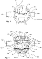
- a pressure regulator according to the present invention is generally designated 100.
- the pressure regulator 100 comprises a main body 1, for example constructed by means of a metal casing.
- the regulator 100 further comprises an inlet opening 101, through which there is introduced inside the regulator a gas at high pressure and an outlet opening 102, through which the gas is discharged once the regulation of pressure and flow rate has been carried out. Therefore, it will be appreciated that the inlet opening 101 is intended to be connected to a gas source at high pressure, such as, for example, a barrel, while the outlet opening 102 is intended to be connected to the burner of a gas apparatus, for example, an oven or a barbecue.
- a gas source at high pressure such as, for example, a barrel
- the outlet opening 102 is intended to be connected to the burner of a gas apparatus, for example, an oven or a barbecue.
- gas pressure reduction means 2 which, in a preferred embodiment, are of the type with a resilient membrane.
- the pressure regulator 100 comprises a first membrane and a second membrane 21, 22.
- the membranes 21 and 22 together with the main body 1 define a chamber 11.
- the membranes 21 and 22 form opposite walls of the chamber 11.
- the chamber 11 is in communication with the inlet opening 101, from which it receives the gas which is intended to be subjected to the pressure reduction, and with the outlet opening 102.
- the resilient membranes 21 and 22 form an example of the pressure reduction means 2 mentioned above, acting on the gas by regulating the pressure thereof in a manner known per se.
- pressure reduction means 2 based, for example, on a single resilient membrane or with other pressure regulation elements.
- the inlet opening 101 communicates with the chamber 11 through a passage 13 which can be selectively opened or closed by means of a closure element 12 which is operatively connected to the membrane 21.
- the closure element 12 is formed by a lever 14 which pivots on a pin 15.
- the lever 14 also has an opening 13A which allows a limited passage of gas, even when the lever is in a closed position on the passage 13.
- An arm of the lever cooperates with the first resilient membrane 21 in such a manner that the action of a spring 21A which is connected to the resilient membrane 21 urges the closure element 12 so as to open.
- the regulator of the present invention further comprises a safety device 3 which is capable of intervening in the event of a condition of excess pressure in the pressure regulator 100.
- the safety device 3 comprises a closure member 30 which is capable of intercepting the inlet opening 101 in the event of a condition of excess pressure, as will be set out in greater detail below.
- the closure member 30 is of the linear type and can move from a closure position of the inlet opening 101 to an open position thereof by means of translation along an axis Y.
- the axis Y coincides with the axis of an inlet pipe 101A which faces the inlet opening 101 and through which the gas is introduced into the chamber 11.
- the closure member 30 further comprises a rod 31 which extends inside the chamber 11 and which is also movable along the translation axis Y.
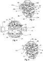
- the closure member 30 is illustrated in Figures 1 to 4 in an open position, that is to say, in a position in which the inlet opening 101 is not intercepted, and therefore in which the gas can be introduced inside the chamber 11.
- closure member 30 is illustrated in a closed position, that is to say, in a position in which the inlet opening 101 is instead intercepted and the flow of the gas inside the chamber 101 is prevented.
- the movement of the closure member 30 from the open position to the closed position is carried out automatically after the occurrence of an excess pressure inside the chamber 101.
- the closure member 30 is operatively connected with the pressure reduction means 2 and preferably with the second membrane 22.
- the rod 31 of the closure member 30 comprises a seat 33, on which a pin 23 which is connected to the second membrane 23 is engaged.
- the seat 33 has at least one inclined surface 33A, which is advantageously directed towards the closure member 30.
- This inclined surface 33A is orientated in such a manner that the seat 33 widens towards the outer edge thereof.
- a sphere 24 which facilitates the movement of the rod 31, the sphere 24 being capable of more easily leaving the seat 33.
- the second membrane 22 urges the pin 23 with the sphere 24 inside the respective seat 33, thereby preventing the axial movement of the rod 31 and, consequently, of the closure member 30.
- the closure member 30 is further urged in the closure direction by means of an additional spring 34.
- the position of the seat 33 is such that, when the sphere 24 is retained inside the seat 33, the closure member 30 is retained in an open position.
- the sphere 24 can leave the seat 33, so that the closure member 30 which is urged by the spring 34 can move into a closure position, thereby intercepting the inlet opening 101 and interrupting the gas flow inside the regulator.
- the pressure regulator 100 of the present invention further comprises a reactivation assembly 4 which is configured to reactivate the safety device 3 in an operative condition so that the gas flow is again allowed inside the chamber 11.
- a reactivation assembly 4 which is configured to reactivate the safety device 3 in an operative condition so that the gas flow is again allowed inside the chamber 11.
- the reactivation assembly 4 comprises a rotatable actuator 40 which can be rotated by the user of the regulator 101 about the rotation axis X thereof, so as to urge the closure member 30 in this opening direction of the inlet opening 101 following the rotation thereof about.
- the rotatable actuator 40 may comprise an operating portion 40A which is operatively connected to the closure member 30 so as to convert the rotation about the rotation axis X of the rotatable actuator 40 into a linear movement of the closure member 30 along the translation axis Y.
- the operating portion 40A includes a cam 41, which is preferably eccentric with respect to the axis X and which is configured so as to abut an end surface 32 of the rod 31 following the rotation of the actuator 40. Therefore, following the rotation of the actuator 40, the cam 41 will have a different position along the axis Y and, moving into contact with the end 32 of the rod 31, it will be positioned so as to consequently move it along the translation axis Y thereof.
- the actuator 40 is free to rotate if it is not urged by external actions by the operator and, therefore, when an excess pressure situation arises, the movement of the rod 31 and closure member 30 is not prevented by the presence of the cam 41 or more generally the operating portion 40A.
- a rotation action of the actuator 40 can urge the closure member 3 so as to open, overcoming the urging action applied by the spring 34.
- the end surface 32 is planar and preferably this planar surface is perpendicular to the translation axis of the closure member.
- the cam 41 defines a peripheral surface which includes a concave portion 41A and a convex portion 41B.
- the concave portion 41A is directed towards the rotation axis of the actuator.
- the concave portion 41A is opposite the convex portion with respect to the rotation axis of the actuator.
- the concave portion 41A can also be formed by a planar portion, which is always preferably opposite the convex portion.
- the convex portion 41B is configured so as to abut the end surface 32 during the reactivation operations of the regulator, preferably sliding along it during the rotation and urging the closure member to move in translation along the translation axis thereof.
- the concave portion 41A instead allows definition of a receiving space for the end of the rod 31, or more generally the closure member 3, when the regulator is blocked when the following safety mechanism becomes operative. This situation is described in an embodiment of the present invention in Figure 5 .
- the gas at high pressure which is supplied, for example, from a barrel which is connected to the inlet opening 101, thereby arrives at the regulator 101 and passes through the opening 13A.
- the user can carry out a reactivation of the regulator by means of the reactivation assembly 4.
- the regulator according to the present invention allows to get a high level of safety and overcomes any temporary malfunctions in a simple and effective manner.
Landscapes
- Engineering & Computer Science (AREA)
- General Engineering & Computer Science (AREA)
- Mechanical Engineering (AREA)
- Physics & Mathematics (AREA)
- Fluid Mechanics (AREA)
- General Physics & Mathematics (AREA)
- Automation & Control Theory (AREA)
- Control Of Fluid Pressure (AREA)
- Fluid-Pressure Circuits (AREA)
- Fuel-Injection Apparatus (AREA)
Claims (15)
- Régulateur de pression (100) comprenant un corps principal (1) à l'intérieur duquel il est défini au moins une chambre (11, 12), une ouverture d'entrée (101) pour introduire dans la au moins une chambre (11, 12) du gaz à haute pression et une ouverture de sortie (102) pour évacuer du gaz à une pression réduite, des moyens pour réduire la pression du gaz (2) et un dispositif de sécurité (3) comprenant un élément de fermeture (30) qui est capable d'intercepter l'ouverture d'entrée (101) en cas de pressions excessives à l'intérieur de la au moins une chambre (11, 12) afin d'empêcher l'écoulement de gaz à l'intérieur de la au moins une chambre (11, 12) et un ensemble de réactivation (4) qui est configuré pour réactiver le dispositif de sécurité (3) dans un état de fonctionnement de sorte que l'écoulement de gaz est à nouveau autorisé à l'intérieur de la au moins une chambre (11, 12), dans lequel l'ensemble de réactivation (4) comprend un organe de commande rotatif (40) qui est configuré de manière à pousser l'élément de fermeture (30) dans une direction d'ouverture de l'ouverture d'entrée (101) après une rotation de celui-ci autour d'un axe de rotation respectif (X), dans lequel l'organe de commande rotatif (40) comprend une came (41) qui est configurée de manière à buter contre l'élément de fermeture (30) après la rotation de l'organe de commande rotatif (40), caractérisé en ce que la came (41) définit une surface périphérique qui inclut une partie concave (41A) et une partie convexe (41B).
- Régulateur de pression (100) selon la revendication 1, dans lequel l'élément de fermeture (30) est configuré pour être poussé, au moyen de l'organe de commande rotatif (40), dans la direction d'ouverture de l'ouverture d'entrée (101) au moyen d'un mouvement le long d'un axe de translation respectif (Y).
- Régulateur de pression (100) selon la revendication 1 ou la revendication 2, dans lequel la came (41) est formée au niveau d'une partie active (40A) qui est fonctionnellement reliée à l'élément de fermeture (30) de manière à convertir la rotation autour de l'axe de rotation (X) de l'organe de commande rotatif (40) en un mouvement linéaire de l'élément de fermeture (30) le long de l'axe de translation (Y).
- Régulateur de pression (100) selon l'une quelconque des revendications 1 à 3, dans lequel la came (41) est configurée de manière à buter contre une surface d'extrémité (32) de l'élément de fermeture (30) après la rotation de l'organe de commande rotatif (40).
- Régulateur de pression (100) selon la revendication 4, dans lequel l'élément de fermeture (30) comprend une tige (31), la surface d'extrémité (32) étant de préférence définie sur la tige (31).
- Régulateur de pression (100) selon la revendication 4 ou la revendication 5, dans lequel la surface d'extrémité (32) est plane.
- Régulateur de pression (100) selon l'une quelconque des revendications précédentes, dans lequel l'élément de fermeture (30) est du type linéaire de manière à définir un axe de translation (Y) de l'élément de fermeture (30).
- Régulateur de pression (100) selon la revendication 7, dans lequel l'axe de rotation (X) de l'organe de commande rotatif (40) est perpendiculaire à l'axe de translation (Y) de l'élément de fermeture (30).
- Régulateur de pression (100) selon la revendication 7 ou la revendication 8, lorsqu'elle dépend de la revendication 5 ou de la revendication 6, dans lequel la surface d'extrémité (32) est sensiblement perpendiculaire à l'axe de translation de l'élément de fermeture.
- Régulateur de pression (100) selon l'une quelconque des revendications précédentes, dans lequel la partie concave (41A) est dirigée vers l'axe de rotation de l'organe de commande rotatif (40).
- Régulateur de pression (100) selon l'une quelconque des revendications précédentes, dans lequel la partie concave (41A) est opposée à la partie convexe (41B) par rapport à l'axe de rotation de l'organe de commande rotatif (40).
- Régulateur de pression (100) selon l'une quelconque des revendications 3 à 7, dans lequel la partie active (40A) est excentrée par rapport à l'axe de rotation (X) de l'organe de commande rotatif (40).
- Régulateur de pression (100) selon l'une quelconque des revendications précédentes, dans lequel l'organe de commande rotatif (40) comprend une extrémité (43) qui fait saillie vers l'extérieur depuis le corps principal (1) de manière à pouvoir être manipulée par un utilisateur.
- Régulateur de pression (100) selon l'une quelconque des revendications précédentes, dans lequel l'élément de fermeture (30) comprend un siège (33), sur lequel un ergot (23) qui est relié à une membrane (22) du moyen de réduction de pression de gaz (2) est engagé.
- Régulateur de pression (100) selon l'une quelconque des revendications précédentes, dans lequel le siège (33) a au moins une surface inclinée (33A).
Applications Claiming Priority (1)
| Application Number | Priority Date | Filing Date | Title |
|---|---|---|---|
| IT102019000002275A IT201900002275A1 (it) | 2019-02-15 | 2019-02-15 | Regolatore di pressione |
Publications (2)
| Publication Number | Publication Date |
|---|---|
| EP3696452A1 EP3696452A1 (fr) | 2020-08-19 |
| EP3696452B1 true EP3696452B1 (fr) | 2022-07-27 |
Family
ID=66589743
Family Applications (1)
| Application Number | Title | Priority Date | Filing Date |
|---|---|---|---|
| EP20157621.2A Active EP3696452B1 (fr) | 2019-02-15 | 2020-02-17 | Régulateur de pression |
Country Status (3)
| Country | Link |
|---|---|
| EP (1) | EP3696452B1 (fr) |
| ES (1) | ES2928805T3 (fr) |
| IT (1) | IT201900002275A1 (fr) |
Family Cites Families (5)
| Publication number | Priority date | Publication date | Assignee | Title |
|---|---|---|---|---|
| US3424194A (en) * | 1966-07-26 | 1969-01-28 | American Meter Co | Overpressure shutoff device |
| FR2813945B1 (fr) * | 2000-09-14 | 2002-10-11 | Novacomet | Robinet-detendeur a montage rapide sur une bouteille de gaz |
| WO2006098577A1 (fr) * | 2005-03-17 | 2006-09-21 | Hucons Technology Co., Ltd. | Regulateur pour gpl a basse pression avec fonction de fermeture automatique |
| FR2984448B1 (fr) | 2011-12-20 | 2014-11-21 | Clesse Ind | Detendeur de gaz a securite de surpression integree |
| US9593782B2 (en) * | 2014-04-30 | 2017-03-14 | Emerson Process Management Regulator Technologies, Inc. | Fluid regulator with field convertible slam-shut device |
-
2019
- 2019-02-15 IT IT102019000002275A patent/IT201900002275A1/it unknown
-
2020
- 2020-02-17 EP EP20157621.2A patent/EP3696452B1/fr active Active
- 2020-02-17 ES ES20157621T patent/ES2928805T3/es active Active
Also Published As
| Publication number | Publication date |
|---|---|
| ES2928805T3 (es) | 2022-11-22 |
| IT201900002275A1 (it) | 2020-08-15 |
| EP3696452A1 (fr) | 2020-08-19 |
Similar Documents
| Publication | Publication Date | Title |
|---|---|---|
| US8550105B2 (en) | Valve system of high pressure tank for vehicle | |
| KR920006495B1 (ko) | 가스 감압장치 | |
| EP2901056B1 (fr) | Soupape de décharge actionnée par pilote avec deux régulateurs pilotes | |
| US3487852A (en) | Relief valve | |
| KR101770023B1 (ko) | 수동 개폐 밸브 | |
| US5103861A (en) | Sealing means for a two-stage gas regulator for liquefied-gas containers | |
| EP3546830A1 (fr) | Robinet à gaz avec une soupape de sûreté destinée à un appareil de cuisson au gaz et appareil de cuisson au gaz intégrant ledit robinet à gaz | |
| EP3696452B1 (fr) | Régulateur de pression | |
| JP7455143B2 (ja) | 係止フックを備えたレバー式バルブ | |
| JP4346610B2 (ja) | 複合弁 | |
| CN101166927A (zh) | 误动作防止手动阀 | |
| CN112212042B (zh) | 气体自动切断装置 | |
| US6564827B1 (en) | Shut-off device for the filling device of a pressure tank | |
| KR102103592B1 (ko) | 가스용기용 밸브 | |
| US11249496B1 (en) | Gas pressure regulator valve | |
| US12147250B2 (en) | Gas-pressure regulator | |
| US4286768A (en) | Stepped pressure gas valve apparatus | |
| US4180241A (en) | Solenoid operated valve and shut-off device | |
| JP4296494B2 (ja) | レギュレータ | |
| KR200330696Y1 (ko) | 보일러용 안전밸브의 배압조절 구조 | |
| JP7084170B2 (ja) | 安全弁及び圧力調整器 | |
| US12487615B2 (en) | Gas-pressure regulator | |
| US5323799A (en) | Fully mechanical pressure relief system | |
| CN108571607B (zh) | 具有相对于容器进料入口定位的阀入口的内部阀系统 | |
| WO2026012753A1 (fr) | Dispositif modulaire de régulation d'un débit de gaz sur une bouteille de gaz à partie réglable |
Legal Events
| Date | Code | Title | Description |
|---|---|---|---|
| PUAI | Public reference made under article 153(3) epc to a published international application that has entered the european phase |
Free format text: ORIGINAL CODE: 0009012 |
|
| STAA | Information on the status of an ep patent application or granted ep patent |
Free format text: STATUS: THE APPLICATION HAS BEEN PUBLISHED |
|
| AK | Designated contracting states |
Kind code of ref document: A1 Designated state(s): AL AT BE BG CH CY CZ DE DK EE ES FI FR GB GR HR HU IE IS IT LI LT LU LV MC MK MT NL NO PL PT RO RS SE SI SK SM TR |
|
| AX | Request for extension of the european patent |
Extension state: BA ME |
|
| STAA | Information on the status of an ep patent application or granted ep patent |
Free format text: STATUS: REQUEST FOR EXAMINATION WAS MADE |
|
| 17P | Request for examination filed |
Effective date: 20210218 |
|
| RBV | Designated contracting states (corrected) |
Designated state(s): AL AT BE BG CH CY CZ DE DK EE ES FI FR GB GR HR HU IE IS IT LI LT LU LV MC MK MT NL NO PL PT RO RS SE SI SK SM TR |
|
| GRAP | Despatch of communication of intention to grant a patent |
Free format text: ORIGINAL CODE: EPIDOSNIGR1 |
|
| STAA | Information on the status of an ep patent application or granted ep patent |
Free format text: STATUS: GRANT OF PATENT IS INTENDED |
|
| RIC1 | Information provided on ipc code assigned before grant |
Ipc: F16K 17/32 20060101AFI20220314BHEP |
|
| INTG | Intention to grant announced |
Effective date: 20220401 |
|
| GRAJ | Information related to disapproval of communication of intention to grant by the applicant or resumption of examination proceedings by the epo deleted |
Free format text: ORIGINAL CODE: EPIDOSDIGR1 |
|
| STAA | Information on the status of an ep patent application or granted ep patent |
Free format text: STATUS: REQUEST FOR EXAMINATION WAS MADE |
|
| GRAS | Grant fee paid |
Free format text: ORIGINAL CODE: EPIDOSNIGR3 |
|
| STAA | Information on the status of an ep patent application or granted ep patent |
Free format text: STATUS: GRANT OF PATENT IS INTENDED |
|
| GRAP | Despatch of communication of intention to grant a patent |
Free format text: ORIGINAL CODE: EPIDOSNIGR1 |
|
| GRAA | (expected) grant |
Free format text: ORIGINAL CODE: 0009210 |
|
| STAA | Information on the status of an ep patent application or granted ep patent |
Free format text: STATUS: THE PATENT HAS BEEN GRANTED |
|
| INTC | Intention to grant announced (deleted) | ||
| INTG | Intention to grant announced |
Effective date: 20220610 |
|
| AK | Designated contracting states |
Kind code of ref document: B1 Designated state(s): AL AT BE BG CH CY CZ DE DK EE ES FI FR GB GR HR HU IE IS IT LI LT LU LV MC MK MT NL NO PL PT RO RS SE SI SK SM TR |
|
| REG | Reference to a national code |
Ref country code: CH Ref legal event code: EP |
|
| REG | Reference to a national code |
Ref country code: DE Ref legal event code: R096 Ref document number: 602020004130 Country of ref document: DE |
|
| REG | Reference to a national code |
Ref country code: AT Ref legal event code: REF Ref document number: 1507267 Country of ref document: AT Kind code of ref document: T Effective date: 20220815 |
|
| REG | Reference to a national code |
Ref country code: IE Ref legal event code: FG4D |
|
| REG | Reference to a national code |
Ref country code: LT Ref legal event code: MG9D |
|
| REG | Reference to a national code |
Ref country code: ES Ref legal event code: FG2A Ref document number: 2928805 Country of ref document: ES Kind code of ref document: T3 Effective date: 20221122 |
|
| REG | Reference to a national code |
Ref country code: NL Ref legal event code: MP Effective date: 20220727 |
|
| PG25 | Lapsed in a contracting state [announced via postgrant information from national office to epo] |
Ref country code: SE Free format text: LAPSE BECAUSE OF FAILURE TO SUBMIT A TRANSLATION OF THE DESCRIPTION OR TO PAY THE FEE WITHIN THE PRESCRIBED TIME-LIMIT Effective date: 20220727 Ref country code: RS Free format text: LAPSE BECAUSE OF FAILURE TO SUBMIT A TRANSLATION OF THE DESCRIPTION OR TO PAY THE FEE WITHIN THE PRESCRIBED TIME-LIMIT Effective date: 20220727 Ref country code: PT Free format text: LAPSE BECAUSE OF FAILURE TO SUBMIT A TRANSLATION OF THE DESCRIPTION OR TO PAY THE FEE WITHIN THE PRESCRIBED TIME-LIMIT Effective date: 20221128 Ref country code: NO Free format text: LAPSE BECAUSE OF FAILURE TO SUBMIT A TRANSLATION OF THE DESCRIPTION OR TO PAY THE FEE WITHIN THE PRESCRIBED TIME-LIMIT Effective date: 20221027 Ref country code: NL Free format text: LAPSE BECAUSE OF FAILURE TO SUBMIT A TRANSLATION OF THE DESCRIPTION OR TO PAY THE FEE WITHIN THE PRESCRIBED TIME-LIMIT Effective date: 20220727 Ref country code: LV Free format text: LAPSE BECAUSE OF FAILURE TO SUBMIT A TRANSLATION OF THE DESCRIPTION OR TO PAY THE FEE WITHIN THE PRESCRIBED TIME-LIMIT Effective date: 20220727 Ref country code: LT Free format text: LAPSE BECAUSE OF FAILURE TO SUBMIT A TRANSLATION OF THE DESCRIPTION OR TO PAY THE FEE WITHIN THE PRESCRIBED TIME-LIMIT Effective date: 20220727 Ref country code: FI Free format text: LAPSE BECAUSE OF FAILURE TO SUBMIT A TRANSLATION OF THE DESCRIPTION OR TO PAY THE FEE WITHIN THE PRESCRIBED TIME-LIMIT Effective date: 20220727 |
|
| REG | Reference to a national code |
Ref country code: AT Ref legal event code: MK05 Ref document number: 1507267 Country of ref document: AT Kind code of ref document: T Effective date: 20220727 |
|
| PG25 | Lapsed in a contracting state [announced via postgrant information from national office to epo] |
Ref country code: PL Free format text: LAPSE BECAUSE OF FAILURE TO SUBMIT A TRANSLATION OF THE DESCRIPTION OR TO PAY THE FEE WITHIN THE PRESCRIBED TIME-LIMIT Effective date: 20220727 Ref country code: IS Free format text: LAPSE BECAUSE OF FAILURE TO SUBMIT A TRANSLATION OF THE DESCRIPTION OR TO PAY THE FEE WITHIN THE PRESCRIBED TIME-LIMIT Effective date: 20221127 Ref country code: HR Free format text: LAPSE BECAUSE OF FAILURE TO SUBMIT A TRANSLATION OF THE DESCRIPTION OR TO PAY THE FEE WITHIN THE PRESCRIBED TIME-LIMIT Effective date: 20220727 Ref country code: GR Free format text: LAPSE BECAUSE OF FAILURE TO SUBMIT A TRANSLATION OF THE DESCRIPTION OR TO PAY THE FEE WITHIN THE PRESCRIBED TIME-LIMIT Effective date: 20221028 |
|
| PG25 | Lapsed in a contracting state [announced via postgrant information from national office to epo] |
Ref country code: SM Free format text: LAPSE BECAUSE OF FAILURE TO SUBMIT A TRANSLATION OF THE DESCRIPTION OR TO PAY THE FEE WITHIN THE PRESCRIBED TIME-LIMIT Effective date: 20220727 Ref country code: RO Free format text: LAPSE BECAUSE OF FAILURE TO SUBMIT A TRANSLATION OF THE DESCRIPTION OR TO PAY THE FEE WITHIN THE PRESCRIBED TIME-LIMIT Effective date: 20220727 Ref country code: DK Free format text: LAPSE BECAUSE OF FAILURE TO SUBMIT A TRANSLATION OF THE DESCRIPTION OR TO PAY THE FEE WITHIN THE PRESCRIBED TIME-LIMIT Effective date: 20220727 Ref country code: CZ Free format text: LAPSE BECAUSE OF FAILURE TO SUBMIT A TRANSLATION OF THE DESCRIPTION OR TO PAY THE FEE WITHIN THE PRESCRIBED TIME-LIMIT Effective date: 20220727 Ref country code: AT Free format text: LAPSE BECAUSE OF FAILURE TO SUBMIT A TRANSLATION OF THE DESCRIPTION OR TO PAY THE FEE WITHIN THE PRESCRIBED TIME-LIMIT Effective date: 20220727 |
|
| REG | Reference to a national code |
Ref country code: DE Ref legal event code: R097 Ref document number: 602020004130 Country of ref document: DE |
|
| PG25 | Lapsed in a contracting state [announced via postgrant information from national office to epo] |
Ref country code: SK Free format text: LAPSE BECAUSE OF FAILURE TO SUBMIT A TRANSLATION OF THE DESCRIPTION OR TO PAY THE FEE WITHIN THE PRESCRIBED TIME-LIMIT Effective date: 20220727 Ref country code: EE Free format text: LAPSE BECAUSE OF FAILURE TO SUBMIT A TRANSLATION OF THE DESCRIPTION OR TO PAY THE FEE WITHIN THE PRESCRIBED TIME-LIMIT Effective date: 20220727 |
|
| PLBE | No opposition filed within time limit |
Free format text: ORIGINAL CODE: 0009261 |
|
| STAA | Information on the status of an ep patent application or granted ep patent |
Free format text: STATUS: NO OPPOSITION FILED WITHIN TIME LIMIT |
|
| PG25 | Lapsed in a contracting state [announced via postgrant information from national office to epo] |
Ref country code: AL Free format text: LAPSE BECAUSE OF FAILURE TO SUBMIT A TRANSLATION OF THE DESCRIPTION OR TO PAY THE FEE WITHIN THE PRESCRIBED TIME-LIMIT Effective date: 20220727 |
|
| 26N | No opposition filed |
Effective date: 20230502 |
|
| PG25 | Lapsed in a contracting state [announced via postgrant information from national office to epo] |
Ref country code: SI Free format text: LAPSE BECAUSE OF FAILURE TO SUBMIT A TRANSLATION OF THE DESCRIPTION OR TO PAY THE FEE WITHIN THE PRESCRIBED TIME-LIMIT Effective date: 20220727 |
|
| REG | Reference to a national code |
Ref country code: DE Ref legal event code: R119 Ref document number: 602020004130 Country of ref document: DE |
|
| PG25 | Lapsed in a contracting state [announced via postgrant information from national office to epo] |
Ref country code: MC Free format text: LAPSE BECAUSE OF FAILURE TO SUBMIT A TRANSLATION OF THE DESCRIPTION OR TO PAY THE FEE WITHIN THE PRESCRIBED TIME-LIMIT Effective date: 20220727 |
|
| REG | Reference to a national code |
Ref country code: CH Ref legal event code: PL |
|
| REG | Reference to a national code |
Ref country code: BE Ref legal event code: MM Effective date: 20230228 |
|
| PG25 | Lapsed in a contracting state [announced via postgrant information from national office to epo] |
Ref country code: LU Free format text: LAPSE BECAUSE OF NON-PAYMENT OF DUE FEES Effective date: 20230217 Ref country code: LI Free format text: LAPSE BECAUSE OF NON-PAYMENT OF DUE FEES Effective date: 20230228 Ref country code: CH Free format text: LAPSE BECAUSE OF NON-PAYMENT OF DUE FEES Effective date: 20230228 |
|
| REG | Reference to a national code |
Ref country code: IE Ref legal event code: MM4A |
|
| PG25 | Lapsed in a contracting state [announced via postgrant information from national office to epo] |
Ref country code: IE Free format text: LAPSE BECAUSE OF NON-PAYMENT OF DUE FEES Effective date: 20230217 Ref country code: FR Free format text: LAPSE BECAUSE OF NON-PAYMENT OF DUE FEES Effective date: 20230228 Ref country code: DE Free format text: LAPSE BECAUSE OF NON-PAYMENT OF DUE FEES Effective date: 20230901 |
|
| PG25 | Lapsed in a contracting state [announced via postgrant information from national office to epo] |
Ref country code: BE Free format text: LAPSE BECAUSE OF NON-PAYMENT OF DUE FEES Effective date: 20230228 |
|
| PG25 | Lapsed in a contracting state [announced via postgrant information from national office to epo] |
Ref country code: IT Free format text: LAPSE BECAUSE OF FAILURE TO SUBMIT A TRANSLATION OF THE DESCRIPTION OR TO PAY THE FEE WITHIN THE PRESCRIBED TIME-LIMIT Effective date: 20220727 |
|
| PG25 | Lapsed in a contracting state [announced via postgrant information from national office to epo] |
Ref country code: BG Free format text: LAPSE BECAUSE OF FAILURE TO SUBMIT A TRANSLATION OF THE DESCRIPTION OR TO PAY THE FEE WITHIN THE PRESCRIBED TIME-LIMIT Effective date: 20220727 |
|
| PG25 | Lapsed in a contracting state [announced via postgrant information from national office to epo] |
Ref country code: BG Free format text: LAPSE BECAUSE OF FAILURE TO SUBMIT A TRANSLATION OF THE DESCRIPTION OR TO PAY THE FEE WITHIN THE PRESCRIBED TIME-LIMIT Effective date: 20220727 |
|
| PGFP | Annual fee paid to national office [announced via postgrant information from national office to epo] |
Ref country code: ES Payment date: 20250331 Year of fee payment: 6 |
|
| PG25 | Lapsed in a contracting state [announced via postgrant information from national office to epo] |
Ref country code: CY Free format text: LAPSE BECAUSE OF FAILURE TO SUBMIT A TRANSLATION OF THE DESCRIPTION OR TO PAY THE FEE WITHIN THE PRESCRIBED TIME-LIMIT; INVALID AB INITIO Effective date: 20200217 |
|
| PG25 | Lapsed in a contracting state [announced via postgrant information from national office to epo] |
Ref country code: HU Free format text: LAPSE BECAUSE OF FAILURE TO SUBMIT A TRANSLATION OF THE DESCRIPTION OR TO PAY THE FEE WITHIN THE PRESCRIBED TIME-LIMIT; INVALID AB INITIO Effective date: 20200217 |
|
| PG25 | Lapsed in a contracting state [announced via postgrant information from national office to epo] |
Ref country code: TR Free format text: LAPSE BECAUSE OF FAILURE TO SUBMIT A TRANSLATION OF THE DESCRIPTION OR TO PAY THE FEE WITHIN THE PRESCRIBED TIME-LIMIT Effective date: 20220727 |
|
| PGFP | Annual fee paid to national office [announced via postgrant information from national office to epo] |
Ref country code: GB Payment date: 20260220 Year of fee payment: 7 |