EP3696464A1 - Gashahn, der für eine gaskupplung verwendet werden kann - Google Patents
Gashahn, der für eine gaskupplung verwendet werden kann Download PDFInfo
- Publication number
- EP3696464A1 EP3696464A1 EP20156878.9A EP20156878A EP3696464A1 EP 3696464 A1 EP3696464 A1 EP 3696464A1 EP 20156878 A EP20156878 A EP 20156878A EP 3696464 A1 EP3696464 A1 EP 3696464A1
- Authority
- EP
- European Patent Office
- Prior art keywords
- cavity
- inlet
- gas
- outlet
- passage
- Prior art date
- Legal status (The legal status is an assumption and is not a legal conclusion. Google has not performed a legal analysis and makes no representation as to the accuracy of the status listed.)
- Withdrawn
Links
- 230000033228 biological regulation Effects 0.000 claims abstract description 43
- 230000001105 regulatory effect Effects 0.000 claims abstract description 33
- 239000000463 material Substances 0.000 claims description 7
- 229910052782 aluminium Inorganic materials 0.000 claims description 6
- XAGFODPZIPBFFR-UHFFFAOYSA-N aluminium Chemical compound [Al] XAGFODPZIPBFFR-UHFFFAOYSA-N 0.000 claims description 6
- 229910001369 Brass Inorganic materials 0.000 claims description 4
- 239000010951 brass Substances 0.000 claims description 4
- 238000007789 sealing Methods 0.000 claims description 4
- RYGMFSIKBFXOCR-UHFFFAOYSA-N Copper Chemical compound [Cu] RYGMFSIKBFXOCR-UHFFFAOYSA-N 0.000 claims description 3
- 238000003780 insertion Methods 0.000 claims description 3
- 230000037431 insertion Effects 0.000 claims description 3
- 229910000831 Steel Inorganic materials 0.000 claims description 2
- 239000010949 copper Substances 0.000 claims description 2
- 229910052802 copper Inorganic materials 0.000 claims description 2
- 239000010959 steel Substances 0.000 claims description 2
- 239000007789 gas Substances 0.000 abstract description 152
- 235000021183 entrée Nutrition 0.000 description 41
- 208000031968 Cadaver Diseases 0.000 description 12
- 241000920340 Pion Species 0.000 description 4
- ATUOYWHBWRKTHZ-UHFFFAOYSA-N Propane Chemical compound CCC ATUOYWHBWRKTHZ-UHFFFAOYSA-N 0.000 description 4
- VNWKTOKETHGBQD-UHFFFAOYSA-N methane Chemical compound C VNWKTOKETHGBQD-UHFFFAOYSA-N 0.000 description 4
- 230000000295 complement effect Effects 0.000 description 3
- 238000010438 heat treatment Methods 0.000 description 3
- 238000007373 indentation Methods 0.000 description 3
- 235000021168 barbecue Nutrition 0.000 description 2
- 239000001273 butane Substances 0.000 description 2
- 239000000314 lubricant Substances 0.000 description 2
- IJDNQMDRQITEOD-UHFFFAOYSA-N n-butane Chemical compound CCCC IJDNQMDRQITEOD-UHFFFAOYSA-N 0.000 description 2
- OFBQJSOFQDEBGM-UHFFFAOYSA-N n-pentane Natural products CCCCC OFBQJSOFQDEBGM-UHFFFAOYSA-N 0.000 description 2
- 239000003345 natural gas Substances 0.000 description 2
- 239000001294 propane Substances 0.000 description 2
- 229910001018 Cast iron Inorganic materials 0.000 description 1
- 230000006978 adaptation Effects 0.000 description 1
- 239000004411 aluminium Substances 0.000 description 1
- 238000005452 bending Methods 0.000 description 1
- 238000002485 combustion reaction Methods 0.000 description 1
- 230000007423 decrease Effects 0.000 description 1
- 238000004512 die casting Methods 0.000 description 1
- 210000005069 ears Anatomy 0.000 description 1
- 230000003631 expected effect Effects 0.000 description 1
- 230000014509 gene expression Effects 0.000 description 1
- 230000003993 interaction Effects 0.000 description 1
- 230000007774 longterm Effects 0.000 description 1
- 230000007246 mechanism Effects 0.000 description 1
- 229910052751 metal Inorganic materials 0.000 description 1
- 239000002184 metal Substances 0.000 description 1
- 230000002093 peripheral effect Effects 0.000 description 1
- 230000000750 progressive effect Effects 0.000 description 1
Images


Classifications
-
- F—MECHANICAL ENGINEERING; LIGHTING; HEATING; WEAPONS; BLASTING
- F23—COMBUSTION APPARATUS; COMBUSTION PROCESSES
- F23N—REGULATING OR CONTROLLING COMBUSTION
- F23N1/00—Regulating fuel supply
- F23N1/007—Regulating fuel supply using mechanical means
-
- F—MECHANICAL ENGINEERING; LIGHTING; HEATING; WEAPONS; BLASTING
- F16—ENGINEERING ELEMENTS AND UNITS; GENERAL MEASURES FOR PRODUCING AND MAINTAINING EFFECTIVE FUNCTIONING OF MACHINES OR INSTALLATIONS; THERMAL INSULATION IN GENERAL
- F16K—VALVES; TAPS; COCKS; ACTUATING-FLOATS; DEVICES FOR VENTING OR AERATING
- F16K27/00—Construction of housing; Use of materials therefor
- F16K27/06—Construction of housing; Use of materials therefor of taps or cocks
- F16K27/062—Construction of housing; Use of materials therefor of taps or cocks with conical plugs
-
- F—MECHANICAL ENGINEERING; LIGHTING; HEATING; WEAPONS; BLASTING
- F16—ENGINEERING ELEMENTS AND UNITS; GENERAL MEASURES FOR PRODUCING AND MAINTAINING EFFECTIVE FUNCTIONING OF MACHINES OR INSTALLATIONS; THERMAL INSULATION IN GENERAL
- F16K—VALVES; TAPS; COCKS; ACTUATING-FLOATS; DEVICES FOR VENTING OR AERATING
- F16K5/00—Plug valves; Taps or cocks comprising only cut-off apparatus having at least one of the sealing faces shaped as a more or less complete surface of a solid of revolution, the opening and closing movement being predominantly rotary
- F16K5/02—Plug valves; Taps or cocks comprising only cut-off apparatus having at least one of the sealing faces shaped as a more or less complete surface of a solid of revolution, the opening and closing movement being predominantly rotary with plugs having conical surfaces; Packings therefor
- F16K5/0207—Plug valves; Taps or cocks comprising only cut-off apparatus having at least one of the sealing faces shaped as a more or less complete surface of a solid of revolution, the opening and closing movement being predominantly rotary with plugs having conical surfaces; Packings therefor with special plug arrangement, e.g. special shape or built in means
-
- F—MECHANICAL ENGINEERING; LIGHTING; HEATING; WEAPONS; BLASTING
- F16—ENGINEERING ELEMENTS AND UNITS; GENERAL MEASURES FOR PRODUCING AND MAINTAINING EFFECTIVE FUNCTIONING OF MACHINES OR INSTALLATIONS; THERMAL INSULATION IN GENERAL
- F16K—VALVES; TAPS; COCKS; ACTUATING-FLOATS; DEVICES FOR VENTING OR AERATING
- F16K5/00—Plug valves; Taps or cocks comprising only cut-off apparatus having at least one of the sealing faces shaped as a more or less complete surface of a solid of revolution, the opening and closing movement being predominantly rotary
- F16K5/08—Details
- F16K5/10—Means for additional adjustment of the rate of flow
- F16K5/103—Means for additional adjustment of the rate of flow specially adapted for gas valves
-
- F—MECHANICAL ENGINEERING; LIGHTING; HEATING; WEAPONS; BLASTING
- F23—COMBUSTION APPARATUS; COMBUSTION PROCESSES
- F23K—FEEDING FUEL TO COMBUSTION APPARATUS
- F23K2900/00—Special features of, or arrangements for fuel supplies
- F23K2900/05002—Valves for gaseous fuel supply lines
-
- F—MECHANICAL ENGINEERING; LIGHTING; HEATING; WEAPONS; BLASTING
- F23—COMBUSTION APPARATUS; COMBUSTION PROCESSES
- F23N—REGULATING OR CONTROLLING COMBUSTION
- F23N2235/00—Valves, nozzles or pumps
- F23N2235/02—Air or combustion gas valves or dampers
-
- F—MECHANICAL ENGINEERING; LIGHTING; HEATING; WEAPONS; BLASTING
- F23—COMBUSTION APPARATUS; COMBUSTION PROCESSES
- F23N—REGULATING OR CONTROLLING COMBUSTION
- F23N2235/00—Valves, nozzles or pumps
- F23N2235/12—Fuel valves
- F23N2235/24—Valve details
-
- F—MECHANICAL ENGINEERING; LIGHTING; HEATING; WEAPONS; BLASTING
- F23—COMBUSTION APPARATUS; COMBUSTION PROCESSES
- F23N—REGULATING OR CONTROLLING COMBUSTION
- F23N2239/00—Fuels
- F23N2239/04—Gaseous fuels
Definitions
- the present description relates to a gas valve making it possible to regulate a gas flow rate selection range and usable for a gas pair.
- a gas valve is used in particular to convey an incoming gas to an outlet in the direction of burners, for example for a gas stove or a gas barbecue.
- a gas valve can use natural gas otherwise called town gas (or NG gas) and / or enriched gas, such as butane or propane (called LP gas).
- NG gas town gas
- LP gas enriched gas
- Most gas valves are designed regardless of the gas used (NG or LP). Indeed, the quantity of gas to be supplied to the burners at the outlet of the valve for an appropriate use differs according to the type of gas.
- the gas valve of the present invention has a cavity diversion system, otherwise known as a bypass system, allowing the valve to be used for a couple of gases.
- Such a gas valve is intended to be used, for example, on a usual gas stove which comprises means for igniting the gas leaving the valve as well as the burners.
- a user may wish to change the type of gas for a more or less dense gas having a greater or lesser calorific value, for example during a move causing him to have a gas supplied by his municipality more or less dense with a more or less important calorific value, or not to have town gas and to have to use LP gas, more dense and supplied in bottle. He then wishes to be able to use the gas available on the same stove, while maintaining a calorific value independent of the gas used, by a simple adaptation without having to change the gas valve.
- the document US 4947891 describes an example of such a gas valve, which conventionally comprises an outgoing gas flow regulating valve with a rotary selector lever, to regulate the outgoing gas flow from a low regulation range called low outgoing flow up to a high regulation range called full outflow.
- the valve aims to provide an additional flow rate to the low outgoing flow rate regulation range, in particular to prevent a gas of too low density from having its ignition extinguish in the low outgoing flow rate regulation range.
- Such a valve comprises a rotating conical part with a screw thread, accessible by a screwdriver along a central axis of the rotary selection lever which makes it possible to regulate the outgoing gas flow, making it possible to provide or not an additional flow over the low range. outgoing gas flow.
- the conical part can be more or less inserted thanks to its screw thread within an internal cavity of the gas valve.
- the internal volume of this cavity is regulated by the volume occupied by the conical part more or less inserted into the cavity.
- such a gas valve is not very effective in adding or removing the additional outgoing gas flow rate to the main outgoing gas flow rate range with a minimum of operation as is desired when changing the type of gas, because it requires tightening a screw to such a length that several turns of the screwdriver are required.
- the aim of the present description is in particular to overcome the aforementioned drawbacks.
- the present gas valve is a solution allowing the user to adapt the entire range of regulation of the gas flow leaving the gas valve by means of a rotary shutter.
- the rotary shutter is of the quarter turn type.
- the rotary shutter is of the one-eighth turn type.
- the rotating shutter is accessible from an open face of the valve, to be turned using a commercial tool.
- a conventionally used tool can for example be a screwdriver, thus adjusting the entire range of gas flow rate exiting in a single movement of rotation of the shutter.
- a gas valve such as the present with a first gas qualified as denser, richer, more concentrated, with a higher calorific value released during its combustion, compared to a second gas
- the The user will have to adapt the flow leaving the tap when he wants to switch to using the second gas with the same tap.
- an outgoing gas flow for a defined intermediate position is insufficient with the second gas and can completely prevent its essential ignition prior to its use to obtain an equivalent power for the intermediate position.
- the gas valve of the present invention thus makes it possible to obtain a constant flow rate, for a given position of the control lever, regardless of the density of the gas used.
- the gas valve presented here thus sees an improved comfort of use compared to the already existing valves.
- the second ignited gas can generate a flame temperature which is insufficiently satisfactory to heat for the same intermediate position.
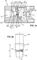
- the terms “interior” and “exterior” and their synonyms are understood to relate to the interior and exterior of the housing 10 (or bearing in industrial jargon), of a cavity, of a corridor, passage or chamber of gas flow control valve 1 or gas tap 7 when said tap 7 is in its final assembled state with valve 1 (visible in figure 1a ).
- the internal volumes of tap 7 are communicating with the external volumes of tap 7 only via an inlet E and an outlet S of tap 7 illustrated on figure 1b .
- a valve 1 as described in the present invention is used to regulate the flow of gas leaving a valve 7 in the direction of burners, for example for a gas stove or a gas barbecue.
- a valve 7 can use natural gas otherwise called town gas or NG gas and / or enriched gas, such as butane or propane otherwise called LP gas.
- the valve 7 of the present invention has a diversion system, otherwise called a bypass system, making it possible to guarantee the same heating power for a pair of gases (GN or LP) whatever the position of the control lever.
- This system consists in providing an additional output flow to a gas of insufficient density. Such an additional flow is obtained by the use of an auxiliary passage P2 additional to a first passage P1, visible in figures 1c and 1d .
- the auxiliary corridor P2 leads to an additional cavity B which joins the following cavity C towards the outlet S of the tap 7, thus adding the flow of the auxiliary corridor P2 to the outlet flow S of the tap 7 via the cavity B.
- the tap 7 may include a notched valve 1 which allows the user an accurate and repeatable selection of the outgoing gas flow rate.
- the figure 1c illustrates a selective sectional view of the valve 7 comprising the valve 1 and the rotary shutter V.
- the valve 1 is out of the selective section and therefore shown fully.
- the shutter V is here in the closed position and the valve 7 does not deliver an additional flow rate leaving the outlet S.
- This valve 7 is in the configuration to favorably use a dense gas, such as an LP gas, not requiring of additional outflow for proper use for a particular gas appliance.
- the valve 7 comprises a body 100 which is made of a material containing aluminum or brass and made for example generally in a core, wire or die casting foundry. This body 100 is provided with the gas inlet E and the gas outlet S.
- the inlet E is intended to receive the gas leaving distribution supplied, for example via a pipe connecting the outlet of an LP gas cylinder to said inlet E.
- the outlet S of the gas valve is intended to be connected to the burners of the gas stove from which the gas to be ignited for heating comes out.
- the body 100 is hollow and comprises a plurality of cavities, corridors and passages intended to connect the gas inlet E to the gas outlet S.
- Each of the so-called cavities, each of the corridors and each of the passages could all indiscriminately be among others called without loss of meaning "cavity”, “corridor”, “passage”, or even “chamber”, “opening”, “hole”, “empty”, “clearance”, “channel”, “gallery”, “ conduit “or” hoses “, to denote a hollow interior volume of the body of the gas valve.
- a first cavity A of the plurality of cavities, corridors and passages extends along a first longitudinal axis Z and has an inlet Ae and a first outlet As1.
- This first cavity A is connected by its inlet Ae to the gas inlet E of the body 100.
- the inlet Ae can be provided along the longitudinal axis Z. Alternatively, the inlet Ae can be provided transversely to the longitudinal axis. Z.
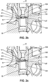
- a regulation cone 103 visible in figures 1c and 1d , extends along the first longitudinal axis Z and has an outer surface Sr. This cone 103 is housed in the inlet Ae and in the first outlet As1 of the first cavity A, so that the outer surface Sr of said cone 103 mouth the first outlet As1 from the first cavity A.
- the regulation cone 103 is able to rotate on itself along the first longitudinal axis Z in the cavity A.
- the first cavity A has a size and a shape adapted to the outer surface Sr of the cone 103, for example a conical shape complementary to said outer surface Sr.
- Known means make it possible to obtain an adequate rotation of the cone 103 in the first cavity A, that is to say sufficiently regular, constant and precise for regulating the gas flow, while wishing to maintain this functionality in the long term.
- a ball bearing or a plain bearing for example can be provided between the cone 103 and the first cavity A.
- a lubricant may be placed in contact with the outer surface Sr of the cone 103 to promote its sliding against the first cavity A.
- the cone 103 is intended to be rotated by the user via a rotary selector lever (not illustrated ) mounted on the valve 7.
- the tap 7 comprises the first corridor P1 after the first cavity A.
- the first corridor P1 has an entrance P1e and an exit P1s.
- the input P1e is directly connected to the first output As1 of the first cavity A.
- the tap 7 further comprises a second cavity B which has a first input Be1 and an output Bs, the first input Be1 of said second cavity B being directly connected to the P1s exit of the first corridor P1.
- the regulation cone 103 makes it possible to regulate the flow of gas in the valve.
- the regulation cone 103 can rotate along the first Z axis in the first cavity A.
- the first range of angular positions of the regulation cone 103 enables the valve 7 to be opened. , that is to say to allow a non-zero flow of gas at the outlet S of the valve 7.
- the second range of angular positions of the regulation cone 103 makes it possible to close the valve 7, that is to say that is to say to prevent any gas flow at the outlet S of the valve 7. It is thus defined that the regulating cone 103 has a first angular position O1 included in the main range U1 of the opening angle of the gas valve.
- the main range U1 is between 90 degrees and approximately 270 to 300 degrees.
- the valve 7 comprises a passage Pr provided in the regulation cone 103 making it possible to connect the inlet Ae of the first cavity A to its first outlet As1, only when said regulation cone 103 is in the first angular position O1.
- the passage Pr does not make it possible to connect the input Ae of the first cavity A to the first output As1 of the first cavity A, because the outer surface Sr of the regulation cone 103 obstructs the first outlet As1 of the first cavity A.
- the regulation cone 103 has a second angular position O2 included in the secondary angle range U2, in which angular position O2 the passage Pr provided in the regulation cone 103 diverges from the first outlet As1 of the first cavity A.
- the passage Pr provided in the regulation cone 103 is such that the main range U1 of opening angle of the valve 7 represents approximately three-quarters of a turn and the secondary range U2 of the closing angle of the valve 7 represents approximately one quarter turn around a given circumference 111 (visible in figure 2a ) of the control cone 103.
- the main angle range U1 of the control cone 103 thus makes it possible to open the valve 7 over approximately three quarters of the range of rotation of the selection lever, that is to say by example about 270 ° to 300 °.
- the range U1 can be between 160 and 250 °, for example 180 ° to 210 °.
- the secondary angle range U2 of the regulation cone 103 makes it possible to close the gas valve over about a quarter of the range of rotation of the rotary selection lever.
- the passage Pr provided in the control cone 103 has a specific shape to obtain a variable regulation according to the second angular position O2 of the regulation cone 103.
- the passage Pr extends around said circumference 111 of the regulation cone 103, and, by definition over any the main angle range U1 which corresponds to the opening of the gas flow.
- a portion 104 of the cone 103 is housed in the first cavity A. Said portion 104 is conical and has a height H along the first longitudinal axis Z.
- the main range U1 of opening angle of the valve 7 represents approximately three quarters.
- the passage Pr provided in the regulation cone 103 has a specific shape to obtain a variable regulation according to the second angular position O2 of the regulation cone 103.
- the circumference 111 is chosen along the first longitudinal axis Z at approximately half the height H of the portion 104 of the cone 103.
- the passage Pr when the cone 103 is inserted into the first cavity A, the passage Pr is substantially centered in height in the first cavity A.
- the passage Pr is thus located opposite both the input Ae and the outputs As1 and As2, when the cone 3 is in the first angle position O1.
- Said passage Pr has a section continuously widening in one direction along said circumference 111.
- the passage Pr when the regulating cone 103 is oriented in the second angular position O2 (valve open), the passage Pr has a certain section K1 opposite the first output As1.
- the opening section K1 increases during a rotation along the first longitudinal axis Z of the cone 103 in a first direction.
- the passage Pr then has a larger section K2 opposite the first exit As1 (see figure 2c ).
- the flow rate exiting the valve 7 is thus increased.
- the opening section K2 decreases during a rotation of the cone 103 in the second direction opposite to the first direction (see figure 2b ).
- the passage Pr then has a smaller section K1 opposite the first output As1.
- the flow rate of the valve 7 is thus reduced.
- Sections K1 and K2 can extend a minimum of 1.5mm.
- Sections K1 and K2 can extend a maximum of 3mm.
- Section K2 can be double the section K1.
- the passage Pr is made in the cone 103 so that the gas flow leaving the valve 7 is adjusted approximately according to a progressive ramp during a continuous rotation of the cone 3.
- the addition of the notch on the bottom of the valve 1 creates defined, stable and repeatable positions of this regulation.
- the passage Pr provided in the cone 103 leads to the first exit As1 which is directly linked to the entry P1e of the first corridor P1.
- the first corridor P1 opens through its output P1s into the second cavity B through its input Be1.
- the cavity B opens directly onto the outlet S of the body 100.
- the second cavity B therefore opens onto the outside of the body 100.
- the auxiliary corridor P2 connects a second outlet As2 of the first cavity A to the inlet Ce a third cavity C.
- the corridors P1 and P2 are cylindrical.
- the second cavity B here opens onto a face F1 called the upper face of the body 100. Said upper face F1 is an exterior face of the body 100.
- the upper face F1 is preferably chosen on an exterior face of the body 100.
- body 100 different from the input face FE E of the body 100 and different from the outlet face FS S of the body 100.
- the shutter V is housed in the cavity B and has a face Fv which opens onto the outside of the body 100 by the outer face F1.
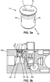
- the figure 3a is a perspective view of the shutter V.
- the shutter V can have an indentation T provided on said face Fv making it possible to rotate the shutter V.
- the indentation T therefore faces the outside of the body 100. It may for example be a slot for flat screwdriver as shown.
- the recess T can also be made in the shape of a cross for a Phillips screwdriver, be a square-shaped blind hole.
- the V shutter may contain brass.
- the body 100 can be of a material containing aluminum. As shown on the figure 3b , a gap J0 may exist in the third cavity C between said body 100 and the shutter V.
- a sealing system J1 can be provided on the shutter V as illustrated on figure 3c .
- the sealing system is for example a seal.
- the seal J1 is thus designed to plug the gap J0 which may exist between the shutter V and the third cavity C.
- the seal J1 can be circular and surrounds the shutter V.
- the valve 7 retains its seal despite the third cavity C opening onto the outside of the body 100 and even in the event of rotation of the shutter V .
- the first longitudinal axis Z passes through the first cavity A at its center and represents the longitudinal axis of the cylindrical housing 100 and of the conical portion 104 of the regulation cone 103.
- the shutter V can rotate about a second longitudinal axis Z '.
- the second longitudinal axis Z ' is parallel to the first longitudinal axis Z and passes through the second cavity B at its center.
- the second longitudinal axis Z ' is coaxial with the shutter V.
- the shutter V closes the additional flow because its outer surface blocks the entrance Ce to the third cavity C.
- FIG 3b On the figure 3b is illustrated a passage Pv provided in the shutter V, defining its input Ve and its output Vs.
- the shutter V is here in an open position, as on the figure 3c , for use of the valve 7 with a gas requiring an additional flow rate at the outlet S, such as NG gas for example.
- the figure 3c shows a cross section of the third cavity C comprising the rotary shutter V and the seal J1 in the gap J0. Entrance Ve is directly opposite exit P2s of the auxiliary corridor P2.
- the shutter V can advantageously comprise a hollow part in the form of a cylinder of revolution, as illustrated in figure 3c .
- the passage Pv then comprises a first hole corresponding to the entry Ve, located on the lateral curved surface Vc of the cylindrical part of the shutter V, and a second hole corresponding to the outlet Vs, located on the disk Vd corresponding to the base which is inside the valve 7 of the cylindrical shape.
- the inlet Ve and the outlet Vs are substantially at right angles.
- the rotary shutter V can thus be rotated from the through position, in which Ve is opposite the inlet Ce, to the closed position, in about a quarter of a turn of the shutter V.
- the figures 4a and 4b are perspective and top views of a gas flow control valve 1, in particular such a valve 1 comprising a notch.
- the valve 1 comprises a housing 10 and a rod 5 (push button).
- the figure 5a shows a housing 10 of the valve 1 having a side wall 2 and a bottom 3.
- This housing 10 can be commonly referred to as a “bearing”.
- This housing 10 can advantageously be metallic. It may contain cast iron or aluminum. It is preferably produced in a foundry, with or without a core or in sheet metal work.
- the side wall 2 is cylindrical and extends along the first longitudinal axis Z to the bottom 3.
- the bottom 3 and the side wall 2 define that the housing 10 is cylindrical and define its interior and its exterior.
- the bottom 3 is circular therefore the housing 10 is a cylinder with a circular base and the interior of the housing 10 is the set of points included on the normals to the concave surface of the side wall 2, the exterior of the housing 10 being all of the points not included inside the housing 10.
- the bottom 3 may be of a non-circular shape, in particular of an elliptical or polygonal shape.
- the bottom 3 is further provided with a through opening 4 which is coaxial with the first longitudinal axis Z along which the cylindrical housing 10 extends. Thus, the opening 4 is centered relative to the bottom 3 of the housing 10.
- the through opening 4 illustrated on figure 5a may be circular and have a diameter of between 40% and 70% of the smallest length of the bottom 3 of the housing 10.
- a rod 5 extends along the first longitudinal axis Z. It is inserted or fitted into the through opening 4 It can slide along the first longitudinal axis Z in the through opening 4. It can turn on itself 360 ° in the through opening 4 along the first longitudinal axis Z.
- the rod 5 may be metallic.
- the rod 5 is an actuator member intended to be rotated along the first axis Z by the user via a rotary selection lever (not shown here). Lubricant may be provided in the through opening 4 in order to facilitate the movements of the rod 5 in the through opening 4.
- a first end T1 of the rod 5 is included in the interior of the housing 10, the second end T2 of the rod 5 being included opposite and outside the housing 10.
- the second end T2 is intended to accommodate the rotary selection handle (not shown here) .
- the second end T2 can in this regard comprise at least one asymmetry, in particular a flat 13 as shown in figure 4a .
- This asymmetry can also for example include an asperity, a bump, a projection, a bore, an indentation, a groove or a chamfer, namely any complementary shape of a rotary selection lever which would accommodate said asymmetry.
- a pin 6 is provided on the rod 5.
- the pin 6 When the rod 5 is disposed in the through opening, the pin 6 extends radially in the direction of the side wall 2 along an axis transverse to the longitudinal axis Z.
- the pin 6 can be in one piece with the rod 5 or be an attached piece fixed to the rod 5.
- the pin 6 is positioned near the first end T1.
- the pin is located at a distance from the first end T1 less than a quarter of the length of the rod 5.
- the pin may be cylindrical in shape. According to other embodiments not shown, the pin 6 can be semi-cylindrical, conical, rounded, have flats or chamfers.
- the pin 6 drives the cone 103 in rotation by a form provided for this purpose in said cone 103.
- the figure 1b shows a groove 20 provided in the cone 103 intended to house the pin 6.
- the cone 103, the pin 6 and the rod 5 can thus be rotated together along the first longitudinal axis Z.
- the integral rotation of these three elements takes place on a corner tertiary shelf U3.
- the tertiary angle range U3 comprises a main range U1 of angles corresponding to the opening of the valve and a secondary range U2 of angles corresponding to the closing of the valve.
- the valve can thus be opened or closed on the tertiary range U3 by turning the rod 5.
- a transverse wall 8 is additionally provided inside the housing 10.
- the transverse wall 8 extends inside the latter along a transverse axis X normal to the first longitudinal axis Z.
- the transverse wall 8 extends inside the latter. from the side wall 2 to the bottom 3.
- the transverse wall 8 replaces one of the projections S1, S2, ... Sn and one of the hollows C1, C2, ... Cn.
- This transverse wall 8 prevents the rotation of the rod 5 over part of the secondary range U2 of total rotation.
- the main range U1 and the secondary range U2 are therefore reduced by the presence of the transverse wall 8.
- transverse wall 8 is an obstacle limiting the range U3 on which the rod 5 can turn is known to man. of the trade to define in particular the closed position and the minimum open position of the gas flow when the pin 6 is on one side or the other of said transverse wall 8. As seen in figure 4a , the pin 6 abuts against the wall 8. Such a device then imposes a first rotational direction for opening the gas flow and, on the other hand, a second rotational direction for closing the gas flow.
- the position of maximum gas flow is advantageously placed at an angle of rotation of the rod 5 which is directly consecutive to the closed position of the gas flow when the user turns the rotary knob for the gas flow in the first rotational direction.
- the rod 5 can translate along the first longitudinal axis Z in the direction of its first end T1 towards its second end T2, until it is blocked when its pin 6 abuts against the bottom 3.
- the rod 5 In the opposite direction of translation , namely from its second end T2 to its first end T1, the rod 5 is blocked when its first end T1 abuts against the valve 7, which stops the translation of the rod 5.
- a means for maintaining the rod 5 at the bottom 3 of the housing 10, that is to say for keeping the pin 6 in abutment against the bottom 3 of the housing 10, can be provided.
- a flange 15 can be provided at the first end T1 of the rod 5.
- said rim 15 may in particular be provided in the extension along the longitudinal axis Z of the peripheral edge of the first end T1.
- the rim 15 can accommodate a support means, for example a spring, (not shown) of the first end T1 against a part of the valve 7 on which the valve 1 is fixed.
- a support means for example a spring, (not shown) of the first end T1 against a part of the valve 7 on which the valve 1 is fixed.
- the pin 6 is intended to be pressed against the bottom 3.
- the bottom 3 of the housing 10 comprises an alternation of projections S1, S2, ... Sn and hollows C1, C2, ... Cn which define a notch.
- the projections S1, S2, ... Sn and the recesses C1, C2, ... Cn each extend radially along a Y axis transverse to the first longitudinal axis Z.
- the transverse axis Y is a radial axis of the housing 10 if the latter is cylindrical.
- the transverse axis Y is substantially close to the bottom 3 and transverse to the first longitudinal axis Z. In particular, it can be orthogonal to the first longitudinal axis Z.
- Each of said hollows is defined as a recess relating to a projection and is positioned between two projections adjacent.
- Each of the sets of a protrusion and a hollow which follow one another defines a notch of the notch.
- the notching is distributed over the whole of the third range U3 for selecting the gas flow rate leaving the valve 1.
- the pin 6 pressed against the base 3 is therefore in direct interaction with the hollows and the projections during a rotation of the rod 5.
- the pin 6 is intended to be housed in and dislodged from successive notches.
- the person skilled in the art chooses a suitable support means.
- a spring can be chosen with a sufficiently low stiffness constant such that a minimum force is necessary to dislodge the pin 6 by a notch.
- the pin 6 provided in the rod 5 therefore comes to bear on the alternation of projections S1, S2, ... Sn and hollows C1, C2, ... Cn.
- the shape of the pin 6 is complementary to the shapes of the projections S1, S2, ... Sn and of the hollows C1, C2, ... Cn to obtain the expected effect of keeping the pin 6 in a notch.
- the diameter of the pin 6 is of the order of magnitude of the height of the projections S1, S2, ... Sn and the depth of the hollows C1, C2, ...
- the pin 6 is cylindrical and has a diameter substantially of the same order of magnitude as the diameter of the hollows C1, C2, ... Cn.
- the figure 6b shows a notch profile according to the embodiment of the figure 6a and how pawn 6 can be accommodated in such a notch.
- pin 6 thus sees its outer cylindrical surface Sp offer maximum contact with the cylindrical interior Sc of the hollow in which it is housed, whereby the dislodgement of the pin 6 from said hollow is limited by friction generated in opposition to this dislodgement.
- the projections and the recesses may advantageously contain fillets, flats and chamfers so as to modulate, during the positioning of the pin 6 in a notch, the areas of friction of the pin 6 with the projections and thus advantageously to modulate the force necessary to the user for dislodging the pin 6 from said notch.
- the figure 4b is a view of the interior of the valve 1 comprising a notch according to an embodiment in which the hollows C1, C2, ... Cn are all identical. According to this embodiment, the hollows C1, C2, ... Cn are semi-cylinders.
- the projections S1, S2, ... Sn extend radially along the Y axis transverse to the first longitudinal axis Z only over a part of the distance from the bottom 3 between the intersection of the through opening 4 with the bottom 3 and the side wall 2 of the housing 10.
- the projections S1, S2, ... Sn are all identical here.
- the projections S1, S2, ... Sn are here half-spheres.
- the projections can be of different geometric shape, for example conical, pyramidal or of rounded shape.
- the figure 5b shows a notch profile according to the embodiment of the figure 5a and how pawn 6 can be accommodated in such a notch.
- the projections and the hollows extend radially from the intersection of the through opening 4 with the bottom 3 and up to the side wall 2 of the housing 10.
- the projections S1, S2, ... Sn are all identical.
- the projections S1, S2, ... Sn each comprise two chamfers, a flat and two fillets which allow the user to hold the cylindrical pin 6 in a hollow between the two chamfers of the hollow.
- the figure 6b shows a notch profile according to the embodiment of the figure 6a and how pawn 6 can be accommodated in such a notch.
- the pin 6 is dislodged from the hollow by driving the rod 5 in rotation and translation along the first longitudinal axis Z.
- figure 7c thus shows the pawn 6 can be dislodged by a notch.
- the chamfers participate by their inclination with respect to the bottom 3 of the housing 10 in accompanying the dislodgement of the pin 6.
- the housing 10 may have an ear 11 as an integral extension of said housing 10 towards the outside.
- the housing 10 can advantageously have two ears.
- Each lug 11 may represent a surplus of material, a surface, a fold, which serves to accommodate a means for fixing said housing 10 on a tap 7, for example a screw for fixing by screwing or a surplus of material for stamping, riveting, bending or clipping.
Landscapes
- Engineering & Computer Science (AREA)
- General Engineering & Computer Science (AREA)
- Mechanical Engineering (AREA)
- Chemical & Material Sciences (AREA)
- Combustion & Propulsion (AREA)
- Taps Or Cocks (AREA)
Applications Claiming Priority (1)
| Application Number | Priority Date | Filing Date | Title |
|---|---|---|---|
| FR1901435A FR3092639A1 (fr) | 2019-02-13 | 2019-02-13 | Robinet de gaz utilisable pour un couple de gaz |
Publications (1)
| Publication Number | Publication Date |
|---|---|
| EP3696464A1 true EP3696464A1 (de) | 2020-08-19 |
Family
ID=67660190
Family Applications (1)
| Application Number | Title | Priority Date | Filing Date |
|---|---|---|---|
| EP20156878.9A Withdrawn EP3696464A1 (de) | 2019-02-13 | 2020-02-12 | Gashahn, der für eine gaskupplung verwendet werden kann |
Country Status (2)
| Country | Link |
|---|---|
| EP (1) | EP3696464A1 (de) |
| FR (1) | FR3092639A1 (de) |
Cited By (1)
| Publication number | Priority date | Publication date | Assignee | Title |
|---|---|---|---|---|
| EP4279809A1 (de) * | 2022-05-20 | 2023-11-22 | Vaillant GmbH | Heizgerät und verwendung einer einstellanordnung |
Citations (5)
| Publication number | Priority date | Publication date | Assignee | Title |
|---|---|---|---|---|
| US3915378A (en) * | 1973-01-08 | 1975-10-28 | Emerson Electric Co | Manifold valve for domestic gas ovens |
| US4947891A (en) | 1987-07-15 | 1990-08-14 | Robertshaw Controls Company | Fuel control device, fuel control system using the device and method of making the device |
| WO2009010400A1 (de) * | 2007-07-13 | 2009-01-22 | BSH Bosch und Siemens Hausgeräte GmbH | Einstellvorrichtung |
| US20110174405A1 (en) * | 2010-01-21 | 2011-07-21 | Lincoln Brass Works, Inc. | Gas valve with dual outlets |
| US20180306436A1 (en) * | 2017-04-21 | 2018-10-25 | Grand Mate Co., Ltd. | Switching device of gas valve |
-
2019
- 2019-02-13 FR FR1901435A patent/FR3092639A1/fr not_active Ceased
-
2020
- 2020-02-12 EP EP20156878.9A patent/EP3696464A1/de not_active Withdrawn
Patent Citations (5)
| Publication number | Priority date | Publication date | Assignee | Title |
|---|---|---|---|---|
| US3915378A (en) * | 1973-01-08 | 1975-10-28 | Emerson Electric Co | Manifold valve for domestic gas ovens |
| US4947891A (en) | 1987-07-15 | 1990-08-14 | Robertshaw Controls Company | Fuel control device, fuel control system using the device and method of making the device |
| WO2009010400A1 (de) * | 2007-07-13 | 2009-01-22 | BSH Bosch und Siemens Hausgeräte GmbH | Einstellvorrichtung |
| US20110174405A1 (en) * | 2010-01-21 | 2011-07-21 | Lincoln Brass Works, Inc. | Gas valve with dual outlets |
| US20180306436A1 (en) * | 2017-04-21 | 2018-10-25 | Grand Mate Co., Ltd. | Switching device of gas valve |
Cited By (1)
| Publication number | Priority date | Publication date | Assignee | Title |
|---|---|---|---|---|
| EP4279809A1 (de) * | 2022-05-20 | 2023-11-22 | Vaillant GmbH | Heizgerät und verwendung einer einstellanordnung |
Also Published As
| Publication number | Publication date |
|---|---|
| FR3092639A1 (fr) | 2020-08-14 |
Similar Documents
| Publication | Publication Date | Title |
|---|---|---|
| EP3696463A1 (de) | Gasdurchsatz-kontrollventil und hahn, der ein solches ventil umfasst | |
| EP1048997A1 (de) | Kartusche für ein Mischventil mit Temperaturbegrenzung | |
| EP1376292A1 (de) | Einarmige thermostatische Kartusche mit Keramikscheiben | |
| FR2807813A1 (fr) | Boitier de vanne de melange de robinet muni de clapets de retenue et d'un filtre | |
| CH631790A5 (fr) | Robinet a cartouche avec plaque rotative. | |
| EP3696464A1 (de) | Gashahn, der für eine gaskupplung verwendet werden kann | |
| EP0667940A1 (de) | Kugel-oder kükenregelventil. | |
| FR2792256A1 (fr) | Aerateur, notamment pour habitacle de vehicule automobile | |
| FR3001001A1 (fr) | Soupape de regulation de pression d'accumulateur de carburant haute pression | |
| FR2828547A3 (fr) | Soupape de securite a double fonction | |
| EP3845807B1 (de) | Verbesserter gaszufuhrhahn für brenner eines gas-kochgeräts | |
| BE1003819A6 (fr) | Boitier en matiere plastique forme d'au moins trois parties pour un coude de conduite de distribution d'eau, et coude de conduite de distribution d'eau destine a etre muni d'un tel boitier. | |
| EP2821168A1 (de) | System für Innenbearbeitung | |
| FR2611849A1 (fr) | Dispositif de reglage interchangeable pour robinet thermostatique | |
| FR2802834A1 (fr) | Dispositif de commande de debit d'eau | |
| EP0000850B1 (de) | Kraftverstärkungs-Mechanismus und damit versehenes Absperrventil | |
| FR2700597A1 (fr) | Clapet de distribution de fluide. | |
| CA3144688A1 (fr) | Robinet a soupape | |
| EP3446192A1 (de) | Mischeinheit und mischarmatur mit solch einer mischeinheit | |
| EP0993583B1 (de) | Ventil für ein gasgerät, und verfahren zum kalibrieren eines solchen ventils | |
| EP1807643B1 (de) | Verschlussstopfen für ein zylindergehäuse | |
| EP1429121A1 (de) | Durchflussregelvorrichtung | |
| EP0533514A1 (de) | Regelungsmittel für Heizungsflüssigkeit | |
| EP3380681B1 (de) | Verankerungselement für ein sanitärbefestigungselement | |
| FR2842463A1 (fr) | Aerateur pour vehicule automobile a debit d'air reglable et flux orientable, et vehicule equipe d'un tel aerateur |
Legal Events
| Date | Code | Title | Description |
|---|---|---|---|
| PUAI | Public reference made under article 153(3) epc to a published international application that has entered the european phase |
Free format text: ORIGINAL CODE: 0009012 |
|
| STAA | Information on the status of an ep patent application or granted ep patent |
Free format text: STATUS: THE APPLICATION HAS BEEN PUBLISHED |
|
| AK | Designated contracting states |
Kind code of ref document: A1 Designated state(s): AL AT BE BG CH CY CZ DE DK EE ES FI FR GB GR HR HU IE IS IT LI LT LU LV MC MK MT NL NO PL PT RO RS SE SI SK SM TR |
|
| AX | Request for extension of the european patent |
Extension state: BA ME |
|
| STAA | Information on the status of an ep patent application or granted ep patent |
Free format text: STATUS: THE APPLICATION IS DEEMED TO BE WITHDRAWN |
|
| 18D | Application deemed to be withdrawn |
Effective date: 20210220 |