EP3696498B1 - Instrument de surveillance et procédé d'étalonnage d'un instrument de surveillance - Google Patents
Instrument de surveillance et procédé d'étalonnage d'un instrument de surveillance Download PDFInfo
- Publication number
- EP3696498B1 EP3696498B1 EP19157547.1A EP19157547A EP3696498B1 EP 3696498 B1 EP3696498 B1 EP 3696498B1 EP 19157547 A EP19157547 A EP 19157547A EP 3696498 B1 EP3696498 B1 EP 3696498B1
- Authority
- EP
- European Patent Office
- Prior art keywords
- axis
- measuring instrument
- alidade
- optical measuring
- instrument
- Prior art date
- Legal status (The legal status is an assumption and is not a legal conclusion. Google has not performed a legal analysis and makes no representation as to the accuracy of the status listed.)
- Active
Links
Images





Classifications
-
- G—PHYSICS
- G01—MEASURING; TESTING
- G01S—RADIO DIRECTION-FINDING; RADIO NAVIGATION; DETERMINING DISTANCE OR VELOCITY BY USE OF RADIO WAVES; LOCATING OR PRESENCE-DETECTING BY USE OF THE REFLECTION OR RERADIATION OF RADIO WAVES; ANALOGOUS ARRANGEMENTS USING OTHER WAVES
- G01S7/00—Details of systems according to groups G01S13/00, G01S15/00, G01S17/00
- G01S7/48—Details of systems according to groups G01S13/00, G01S15/00, G01S17/00 of systems according to group G01S17/00
- G01S7/497—Means for monitoring or calibrating
-
- G—PHYSICS
- G01—MEASURING; TESTING
- G01C—MEASURING DISTANCES, LEVELS OR BEARINGS; SURVEYING; NAVIGATION; GYROSCOPIC INSTRUMENTS; PHOTOGRAMMETRY OR VIDEOGRAMMETRY
- G01C15/00—Surveying instruments or accessories not provided for in groups G01C1/00 - G01C13/00
- G01C15/002—Active optical surveying means
- G01C15/004—Reference lines, planes or sectors
- G01C15/006—Detectors therefor
-
- G—PHYSICS
- G01—MEASURING; TESTING
- G01C—MEASURING DISTANCES, LEVELS OR BEARINGS; SURVEYING; NAVIGATION; GYROSCOPIC INSTRUMENTS; PHOTOGRAMMETRY OR VIDEOGRAMMETRY
- G01C1/00—Measuring angles
- G01C1/02—Theodolites
- G01C1/04—Theodolites combined with cameras
-
- G—PHYSICS
- G01—MEASURING; TESTING
- G01C—MEASURING DISTANCES, LEVELS OR BEARINGS; SURVEYING; NAVIGATION; GYROSCOPIC INSTRUMENTS; PHOTOGRAMMETRY OR VIDEOGRAMMETRY
- G01C15/00—Surveying instruments or accessories not provided for in groups G01C1/00 - G01C13/00
- G01C15/002—Active optical surveying means
-
- G—PHYSICS
- G01—MEASURING; TESTING
- G01C—MEASURING DISTANCES, LEVELS OR BEARINGS; SURVEYING; NAVIGATION; GYROSCOPIC INSTRUMENTS; PHOTOGRAMMETRY OR VIDEOGRAMMETRY
- G01C25/00—Manufacturing, calibrating, cleaning, or repairing instruments or devices referred to in the other groups of this subclass
- G01C25/005—Manufacturing, calibrating, cleaning, or repairing instruments or devices referred to in the other groups of this subclass initial alignment, calibration or starting-up of inertial devices
-
- G—PHYSICS
- G01—MEASURING; TESTING
- G01S—RADIO DIRECTION-FINDING; RADIO NAVIGATION; DETERMINING DISTANCE OR VELOCITY BY USE OF RADIO WAVES; LOCATING OR PRESENCE-DETECTING BY USE OF THE REFLECTION OR RERADIATION OF RADIO WAVES; ANALOGOUS ARRANGEMENTS USING OTHER WAVES
- G01S17/00—Systems using the reflection or reradiation of electromagnetic waves other than radio waves, e.g. lidar systems
- G01S17/02—Systems using the reflection of electromagnetic waves other than radio waves
- G01S17/06—Systems determining position data of a target
- G01S17/42—Simultaneous measurement of distance and other co-ordinates
-
- G—PHYSICS
- G01—MEASURING; TESTING
- G01S—RADIO DIRECTION-FINDING; RADIO NAVIGATION; DETERMINING DISTANCE OR VELOCITY BY USE OF RADIO WAVES; LOCATING OR PRESENCE-DETECTING BY USE OF THE REFLECTION OR RERADIATION OF RADIO WAVES; ANALOGOUS ARRANGEMENTS USING OTHER WAVES
- G01S17/00—Systems using the reflection or reradiation of electromagnetic waves other than radio waves, e.g. lidar systems
- G01S17/88—Lidar systems specially adapted for specific applications
- G01S17/89—Lidar systems specially adapted for specific applications for mapping or imaging
-
- G—PHYSICS
- G01—MEASURING; TESTING
- G01S—RADIO DIRECTION-FINDING; RADIO NAVIGATION; DETERMINING DISTANCE OR VELOCITY BY USE OF RADIO WAVES; LOCATING OR PRESENCE-DETECTING BY USE OF THE REFLECTION OR RERADIATION OF RADIO WAVES; ANALOGOUS ARRANGEMENTS USING OTHER WAVES
- G01S7/00—Details of systems according to groups G01S13/00, G01S15/00, G01S17/00
- G01S7/48—Details of systems according to groups G01S13/00, G01S15/00, G01S17/00 of systems according to group G01S17/00
- G01S7/481—Constructional features, e.g. arrangements of optical elements
-
- G—PHYSICS
- G01—MEASURING; TESTING
- G01S—RADIO DIRECTION-FINDING; RADIO NAVIGATION; DETERMINING DISTANCE OR VELOCITY BY USE OF RADIO WAVES; LOCATING OR PRESENCE-DETECTING BY USE OF THE REFLECTION OR RERADIATION OF RADIO WAVES; ANALOGOUS ARRANGEMENTS USING OTHER WAVES
- G01S7/00—Details of systems according to groups G01S13/00, G01S15/00, G01S17/00
- G01S7/48—Details of systems according to groups G01S13/00, G01S15/00, G01S17/00 of systems according to group G01S17/00
- G01S7/481—Constructional features, e.g. arrangements of optical elements
- G01S7/4811—Constructional features, e.g. arrangements of optical elements common to transmitter and receiver
-
- G—PHYSICS
- G01—MEASURING; TESTING
- G01S—RADIO DIRECTION-FINDING; RADIO NAVIGATION; DETERMINING DISTANCE OR VELOCITY BY USE OF RADIO WAVES; LOCATING OR PRESENCE-DETECTING BY USE OF THE REFLECTION OR RERADIATION OF RADIO WAVES; ANALOGOUS ARRANGEMENTS USING OTHER WAVES
- G01S7/00—Details of systems according to groups G01S13/00, G01S15/00, G01S17/00
- G01S7/48—Details of systems according to groups G01S13/00, G01S15/00, G01S17/00 of systems according to group G01S17/00
- G01S7/497—Means for monitoring or calibrating
- G01S7/4972—Alignment of sensor
-
- G—PHYSICS
- G01—MEASURING; TESTING
- G01C—MEASURING DISTANCES, LEVELS OR BEARINGS; SURVEYING; NAVIGATION; GYROSCOPIC INSTRUMENTS; PHOTOGRAMMETRY OR VIDEOGRAMMETRY
- G01C1/00—Measuring angles
- G01C1/02—Theodolites
Definitions
- a surveying instrument typically comprises a base, an alidade rotatable about a first axis relative to the base, and an optical measuring instrument having a measuring axis rotatable about a second axis relative to the alidade.
- the base is used for mounting the instrument on the ground, a floor, a wall, or any other object and may include, for example, a tripod.
- the base defines the first axis about which the alidade is rotatable relative to the base.
- the base is mounted such that the first axis is orientated in the vertical direction.
- the alidade defines the second axis about which the optical measuring instrument is rotatable relative to the alidade.
- the first and second axes are orthogonal to each other.
- the optical instrument defines the measuring axis which is an axis of the measuring instrument along which a measurement can be performed using the optical instrument.
- the optical measuring instrument can be of a type emitting a laser beam along the measuring axis and detecting laser light of the beam reflected from an object in order to determine the distance between the object and the optical measuring instrument.
- the measuring axis and the second axis are typically orientated orthogonal to each other.
- the provided beam path between the light source and the detector includes the portion extending between the component fixed to the base and the component fixed to the measuring instrument, and it may include further portions upstream or downstream of this particular portion. Again, these further portions of the beam path can be defined using other components, such as lenses, beam splitters and mirrors, mounted on the base, the alidade and the optical measuring instrument.
- the beam path further exists for a second range of rotational positions of the optical measuring instrument about the second axis, wherein the second range is different from the first range.
- the orientation of the measuring instrument relative to alidade has to be changed by more than ⁇ /10 or ⁇ /2 between a first orientation in which the measuring instrument is orientated at the center of the first range and a second orientation at which the measuring instrument is orientated at the center of the second range.
- the beam path is not required to exist for orientations other than orientations within the first and second ranges.
- the beam path may also exist for other orientations outside the first and second ranges.
- the at least one error includes a deviation of an angle between the measuring axis and the second axis and an expected angle between the measuring axis and the second axis. This error is referred to as collimation error in the art.
- the optical measuring instrument When the surveying instrument is used, the optical measuring instrument is oriented such that the measuring light beam points to a desired location on the distant object, and the measuring light beam can be used to perform a measurement, such as to determine the distance of the selected location from the surveying instrument.
- the image of the object recorded using the detector can be monitored.
- the image may include a representation of a reticle or similar element indicating the position in the image corresponding to the location on the distant object onto which the measuring light beam is directed.
- it is desirable that the position in the image indicated by the reticle exactly corresponds to the location on the distant object onto which the measuring light beam is directed.
- the method allows to determine a pixel of the detector onto which the location of the distant object is imaged onto which the beam of measuring light is directed. This pixel is also referred to as the center pixel of the detector in the art.
- FIGS 1A to 1D are schematic illustrations of an exemplary surveying instrument wherein each figure illustrates a certain type of axis error of the surveying instrument 1.
- the surveying instrument 1 is a theodolite in the illustrated example.
- the surveying instrument 1 comprises a base 3 which includes a tripod 5, and an alidade 7 which is rotatable relative to the base 3 about a first axis 9.
- the tripod 5 is used to adjust the orientation of the base 3 such that the first axis 9 is parallel to the vertical direction defined by the gravity vector at the location of the instrument 1.
- the surveying instrument 1 further comprises an optical measuring instrument 11 which is mounted on the alidade 7 such that it is rotatable relative to the alidade 7 about a second axis 13.
- the illustrated surveying instrument is designed such that the second axis 13 is orientated orthogonally to the first axis 9.
- the measuring instrument includes optics 15, such as a telescope, defining a measuring axis 17 along which a measurement can be performed using the optical measuring instrument 11.
- the measuring axis 17 can be indicated by a reticle in the visual field of the telescope, and the user can direct the measuring axis 17 to an object of interest in the visual field of the telescope by rotating the measuring instrument 11 about the second axis 9 and the alidade 7 about the first axis 9.
- the user can then determine the orientations about the first and second axes 9, 13 by reading scales provided on the instrument or electronic signals generated by encoders associated with the first and second axes 9, 13 in the surveying instrument 1. Based on these readings, an angular position of the object of interest can be determined relative to a coordinate system associated with the base 3. The calculation of this orientation depends on the readings of the rotational positions about the first and second axes 9, 13 as inputs. The calculation further depends on assumptions on the geometry of the surveying instrument 1. The assumptions on the geometry include the orientations of the first axis, the second axis and the measuring axis relative to each other. If the configuration of the surveying instrument 1 deviates from these assumptions, this will result in an inaccurate calculation of the orientation of the measuring axis in the coordinate system.
- Figure 1C illustrates a type of error known as the trunnion axis error in the art. This error is indicative of an angle 25 between the second axis 13 and a direction 27 which is exactly orthogonal to the first axis 9.
- Figure 1D illustrates an error known as the tilting axis error in the art, which is indicative of an angle 29 between the second axis 9 and the vertical direction 31 as defined by gravity at the location of the instrument 1.
- the tilting axis error is a set-up error introduced by the user when mounting the instrument 1 and cannot be eliminated by a calibration of the instrument itself.
- the other three errors, the vertical index error, the collimation error, and the trunnion axis error depend only on the configuration of the surveying instrument 1 itself and are errors intrinsic to the instrument.
- the embodiments of calibration methods illustrated below seek to determine these or other types of errors of a surveying instrument.
- FIG 2 is a schematic illustration of a surveying instrument 1.
- the surveying instrument 1 comprises a base 3 and an alidade 7 which is mounted on the base 3 such that it is rotatable relative to the base 3 about a first axis 9.
- the surveying instrument 1 further comprises an optical measuring instrument 11 which is mounted on the alidade 7 such that it is rotatable about a second axis 13 relative to the alidade 7.
- the second axis 13 is substantially orthogonal to the first axis 9.
- the measuring instrument 11 includes optics, such as a telescope, which is schematically represented by a front lens 35 in figure 2 .
- the optics mounted on the measuring instrument defines a measuring axis 17 which is substantially orthogonal to the second axis 13.
- the measuring instrument 11 is further orientated about the second axis 13 relative to the alidade 7 such that the measuring axis 17 is orthogonal to the first axis 9 and the plane of the drawing.
- the surveying instrument 1 further comprises a calibration system 37 which can be used to determine properties of the surveying instrument 1. These properties may in particular include information on the relative orientations of the first axis 9, the second axis 13 and the measuring axis 17.
- the calibration system 37 comprises optical components providing a beam path between a light source 5 and a detector 41.
- the optical components may include, apart from the light source 39 and the detector 41, lenses, mirrors and beam splitters or other suitable optical components which can be used to provide a suitable beam path between the light source 31 and the detector 41.
- the light emitted from the light source 39 traverses a pinhole 45 including a plate having a small opening such that a divergent beam of light is formed downstream of the pinhole 45. This beam is collimated by a lens 43.
- LED light emitting diode
- the calibration system 37 comprises an actuator 44 controlled by the controller 55 and configured to displace the collimating lens 43 in a direction of its optical axis as indicated by arrow 46 in figure 2 .
- the actuator 44 can be controlled in order to adjust the collimation of the beam generated from light source 39 and to adjust a focus generated on the detector 41 from an incoming beam.
- the light beam is subsequently incident on a beam splitter 47 from which a portion of the light beam is reflected.
- the portion of the light beam reflected from the beam splitter 47 is incident on a beam splitter 49 having a mirror surface 50 reflecting the light beam.
- the mirror surface 50 is positioned such that the first axis 9 intersects the mirror surface 50, and it is orientated such that the light beam reflected from the mirror surface 50 travels in a direction substantially parallel to the first axis 9.
- the light beam reflected from the mirror surface 50 traverses the alidade 7 and is incident on a mirror surface 51 provided on a mirror 52.
- the mirror 52 can be provided by a glass plate having two parallel main surfaces, wherein one surface carries a metal layer.
- the metal layer has two opposite reflective surfaces 51 and 51' wherein light beam is reflected from the reflective surface 51 in the situation shown in figure 2 .
- the mirror 52 is fixed to the measuring instrument 11 such that it has a fixed mechanical position and orientation relative to the measuring axis 17.
- the light of the light beam incident on the mirror 52 and reflected from the mirror surface 51 travels back to the beam splitter 49 where it is reflected from the mirror surface 50 such that it is directed to the beam splitter 47, traversing the collimation lens 43. A portion of this light traverses the beam splitter 47 without being reflected such that it is incident on the detector 41.
- the detector 41 is arranged at a same distance from the collimation lens 43 as the pin hole 45 such that the beam is substantially focused on the detector 41.
- the illustrated beam path of the light beam from the light source 39 to the detector 41 comprises plural portions: a portion between the light source 39 and the beam splitter 47, a portion extending from the beam splitter 47 to the beam splitter 49 mounted on the base 3, a portion extending from the beam splitter 49 to the mirror 52 mounted on the optical measuring instrument 11, a portion extending from the mirror 52 mounted on the measuring instrument 11 to the beam splitter 49 mounted on the base 3, a portion extending from the beam splitter 49 to the beam splitter 47, and a portion extending from the beam splitter 47 to the detector 41.
- the detector 41 is a position sensitive detector such that a position at which the light beam is focused on the detector 41 can be determined from signals generated by the detector 41.
- the detector 41 comprises an array of detector pixels wherein each detector pixel provides a light detector.
- the position of the incident light beam on the detector can be determined from detection signals generated by the array of detector pixels.
- the light beam can be simultaneously incident on plural detector pixels.
- the determination of the position of the light beam on the detector may include a determination of a center of gravity of the light intensity incident on the detector 41 and detected by the detector 41.
- the surveying instrument 1 may include a controller 55 including a calculator, such as a microcomputer, analyzing the detection signals generated by the detector and generating light position data representing the position on the detector 41 where the light beam is incident on the detector 41.
- the light position data can be generated based on the center of gravity of the detected light intensity as illustrated above.
- the positions of incidence of the light beam on the detector 41 will be arranged on a substantially straight line on the detector 41.
- Figure 3 is an illustration of measuring results obtained with the calibration system 37 of the surveying instrument shown in figure 2 .
- the performing of one measurement includes orienting the alidade 7 to a given rotational position about the first axis 9, orienting the measuring instrument 11 to a given rotational position relative to the alidade 7 about the second axis 13, reading a detected image from the detector 41, determining the position of the incident light beam within the read image, and recording the light position data corresponding to the determined position.
- one measurement is characterized by two rotational positions and the light position data associated with these two rotational positions.
- the light beam is reflected from the reflective surface 51' while it is reflected from the other reflective surface 51 in the situation shown in figure 2 .
- the mirror 52 is advantageously arranged on the optical measuring instrument 11 such that it does not interfere with the function provided by the optical measuring instrument 11.
- the mirror 52 can be arranged outside of the beam path of the telescope 35 of the measuring instrument 11.
- the surveying instrument 1 differs from this ideal configuration in that the second axis 13 is not exactly orthogonal to the first axis 9 and in that the flat mirror surface 51 is not exactly parallel to the second axis 13. Both deviations contribute to the minimum radii r1 and r2 of the circles 64 illustrated above.
- the first deviation which is the deviation of the angle between the first and second axes 9 and 13, respectively, from 90°, is the trunnion axis error k of the surveying instrument 1.
- the second deviation which is the deviation of the orientation of the mirror surface 51 from parallel to the second axis 13, can be referred to as a "collimation error" cx of the mirror 52.
- the trunnion axis error k determined based on the two sets of measurements illustrated above is important information relating to the performance of the surveying instrument 1 and can be used to correct measurements performed using the surveying instrument 1.
- Figure 6 shows further details of the optical measuring instrument 11.
- the optical measuring instrument 11 comprises a measuring light source 71 emitting a measuring light beam which traverses a beam splitter 73 and is collimated and further shaped by optics not shown in figure 6 .
- the measuring light beam is emitted from the optical measuring instrument 11 through a front lens 35.
- the light beam emitted from the optical measuring instrument 11 is directed to an object of interest, and light reflected back from the object of interest is received through the front lens 35 and directed onto a detector 75 by the beam splitter 73.
- the detector can be of a type suitable for performing the function of the surveying instrument 11.
- the detector 75 can be configured to determine a time when a light pulse is received back from the object of interest to determine the distance of the object of interest from the measuring instrument 11 if the surveying instrument 11 is an electronic distance meter, or the detector 75 can be a position sensitive detector if the surveying instrument 11 is a total station.
- a set of sixteen measurements is performed using the calibration system 37 in the configuration shown in figure 6 . Again, the sixteen measurements are performed at four different rotational positions of the optical measuring instrument 11 about the second axis 13 and four different rotational positions of the alidade 7 about the first axis 9. The positions of incidence of the light beam on the detector 41 obtained from these measurements are illustrated in figure 7 showing these positions in the coordinate system of the detector 41 corresponding to figures 3 and 5 . It is apparent from figure 7 that light positions obtained from measurements performed at the same given rotational positions of the alidade 7 about the first axis 9 but different given rotational positions of the optical measuring instrument 11 about the second axis 13 are also arranged on straight lines 61 shown in figure 7 , similar to figures 3 and 5 .
- Both the collimation error c of the surveying instrument 1 and the trunnion axis error k are important information relating to the performance of the surveying instrument 1 and can be used to correct measurements performed using the surveying instrument 1.
- FIG 8 schematically illustrates a surveying instrument 1 according to a second embodiment comprising a calibration system 37 which can be used to determine some errors of the surveying instrument 1.
- the surveying instrument 1 shown in figure 8 is similar to the surveying instrument illustrated with reference to figures 2 to 7 in that it comprises a base 3, an alidade 7 rotatable relative to the base 3 about a first axis 9, and an optical measuring instrument 11 rotatable relative to the alidade 7 about a second axis 13.
- the surveying instrument 1 is also configured to provide a calibration beam path between a light source 39 and a detector 41 for two different ranges of rotational positions of the optical measuring instrument 11 about the second axis 13.
- the light beam is reflected from the mirror 91 and traverses the beam splitter 87 wherein it is transmitted through the semitransparent surface 88.
- the light beam then traverses the beam splitter 83 wherein it traverses the semi-transparent surface 84 to be incident on a reflecting surface 51 of a mirror 52 fixed to the measuring instrument 11.
- Light reflected from the mirror 52 travels back to the beam splitter 83 wherein it is reflected from the semitransparent surface 84 towards the beam splitter 47.
- the light traverses the collimating lens 43 and the beam splitter 47 and is incident on the detector 41.
- a set of plural measurements is performed at different rotational positions of the alidade about the first axis and different rotational positions of the optical measuring instrument 11 about the second axis 13 when the optical measuring instrument 11 is in the configuration in which the mirror 52 is in the upper position shown in broken lines in figure 8 .
- a set of sixteen measurements can be performed with four different rotational positions of the measuring instrument 11 and for different rotational positions of the alidade 7 such that the corresponding detected light positions on the detector 41 are arranged along straight lines 61 and circles 63 as shown in figure 5 .
- a radius r2 of a smallest possible circle 64 can be determined from this set of measurements.
- the trunnion axis error k of the surveying instrument 1 can be determined using formulas (3) and (4) above based on the values of r1 and r2 obtained from the two sets of measurements.
- the collimation error c of the surveying instrument 1 can then be determined using formula (6) based of the determined radius r3 and the previously determined trunnion axis error k of the surveying instrument 1.
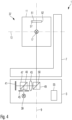
- the optical measuring instrument 11 of the surveying instrument 1 shown in figure 9 is oriented such that the measuring axis is oriented substantially parallel to the first axis 9, and measuring light generated by the light source 71 of the optical measuring instrument 11 is directed towards the alidade 7 and base 3.
- the light beam emitted from a front lens 35 of the optical measuring instrument 11 is incident on a prism 101 having an internal semitransparent surface 102 and a reflecting inner surface 103 arranged at a distance from the semitransparent surface 102.
- the light beam incident of the prism 101 in figure 9 traverses the prism 101 wherein it traverses the semitransparent surface 102 and is incident on a detector 41 fixed to the base 3.
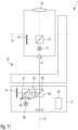
- the optical measuring instrument 11 of the surveying instrument 1 shown in figure 9 is oriented as shown in figure 10 where the light beam emitted from the optical measuring instrument 11 is incident on the reflecting inner surface 103 of the prism 101.
- the reflecting inner surface 103 is oriented such that the light beam reflected from the reflecting inner surface 103 is incident on the semitransparent surface 102 of the prism 101 and reflected therefrom towards the detector 41.
- the radii r1 and r2 can be advantageously used to determine errors of the surveying system 1.
- r1 and r2 were used to determine the trunnion axis error k of the surveying instrument 1 and the collimation error cx of the mirror 52. It was assumed that the collimation error cx of the mirror 52 entered formulas (1) and (2) with opposite signs since the two rotational positions of the measuring instrument relative to the alidade were opposite positions differing by 180°.
- the measurement is not made against an additional mirror (mirror 52) fixed to the measuring instrument 11 but by using the light source of the measuring instrument 11 itself.
- the retroreflector 111 can be mounted on the optical measuring instrument 11 at any suitable location such that there exists an orientation of the optical measuring instrument 11 about the second axis 13 relative to the alidade 7 such that a beam path exists between the retroreflector 111 provided on the optical measuring instrument 11 and the light source 39 of the calibration system 37.
- the light source 39 of the calibration system 37 is provided on the base 3, together with the detector 41 of the calibration system 39.
- the light source of the calibration system can be mounted on the alidade, such as in the embodiment illustrated with reference to figure 8 above, wherein a portion of the beam path of the calibration system 37 extends between a component mounted on the base and a component mounted on the alidade, or a component mounted on the base and the retroreflector 111 mounted on the measuring instrument 11, for example.
- Light generated by the light source 39 and emitted from the pinhole 45 is collimated by the lens 43, reflected from the reflecting surface 50 of the beam splitter 49 such that a beam of measuring light is directed towards the retroreflector 111.
- This beam is inverted in its direction by the retroreflector 111 such that it travels back towards the beam splitter 49, which directs the beam to the lens 43 which focuses the beam on the detector 41.
- the detection signals of the detector 41 can be evaluated in order to determine light positions indicating the location of incidence of the focused beam on the detector 41.
- Figure 12 shows the location of incidence of the focused beam on the detector 41 in the configuration shown in figure 11 in the two-dimensional coordinate system already used in figures 3 , 5 and 7 at reference numeral 113.
- Reference numeral 115 in figure 12 indicates the location of the centers 65 of the circles derived from the measurements illustrated with reference to figure 7 above.
- the surveying instrument 1 is in the configuration shown in figure 6 in which the optical measuring instrument 11 is oriented about the second axis 13 such that the beam of light generated by the light source 71 of the optical measuring instrument 11 is focused on the detector 41.
- the location of the centers of the circles are determined by an angle between the optical axis of the collimation lens 43 and the first axis 9 of rotation of the alidade 7 about the base 3.
- Figure 6 further shows a mirror 121 provided on the base to establish a beam path from the light source 71 of the optical measuring instrument 11 via the mirror 121 to the detector 75 of the optical measuring instrument 11. Moreover, a beam path can also be established between the light source 71 the optical measuring instrument 11 to the detector 41 of the calibration system 37.
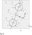
- Figure 13 is an illustration of a detection surface 122 of the detector 75 of the optical measuring instrument 11.
- the detection surface 122 includes an array of pixels 123.
- a first set of measurements is performed at plural different orientations of the alidade 7 about the first axis 9 and at a same first orientation of the optical measuring instrument 11 about the second axis 13.
- the orientation of the optical measuring instrument 11 about the second axis 13 can be 199 gon.
- Reference numerals 125 in figure 13 indicate positions on the detection surface 122 determined as the positions of the light beam based on the light intensities detected by the pixels 123 of the detector 75 in plural measurements of the first set of measurements.
- Reference numeral 129 in figure 13 indicates a center of a circle 130 fitted through the plural positions 125.
- reference numeral 131 in figure 13 indicates a center of a circle 132 fitted through the plural positions 127.
- Reference numeral 135 in figure 13 indicates a line fitted through the plural centers 129 and 131 of the circles 130 and 132, respectively.
- the line 135 represents those locations on the detection surface 122 of the detector 75 where the first axis 9 intersects the detection surface.
- the intersection of the first axis 9 with the detection surface 122 is to be understood such that the first axis 9 is folded by the beam splitter 73 as it were a light beam.
- Figure 13 further shows a vector c oriented parallel to line 139 and attached to the head of vector k.
- the length of the vector c is determined based on the collimation error c determined as illustrated above.
- the length of the sum of the vectors k and c corresponds to the sum of the trunnion axis error and the collimation error.
- Figure 13 further shows a vector i oriented parallel to line 135 and attached to the head of vector c.
- the length of the vector i is determined based on the vertical index error i determined as illustrated above.
Landscapes
- Engineering & Computer Science (AREA)
- Physics & Mathematics (AREA)
- General Physics & Mathematics (AREA)
- Radar, Positioning & Navigation (AREA)
- Remote Sensing (AREA)
- Computer Networks & Wireless Communication (AREA)
- Electromagnetism (AREA)
- Manufacturing & Machinery (AREA)
- Length Measuring Devices By Optical Means (AREA)
- Photometry And Measurement Of Optical Pulse Characteristics (AREA)
- Measurement Of Optical Distance (AREA)
Claims (14)
- Procédé d'étalonnage d'un instrument d'arpentage (1), dans lequel l'instrument d'arpentage (1) comprend : une base (3) ;
une alidade (7) pouvant tourner autour d'un premier axe (9) par rapport à la base (3) ; et
un instrument de mesure optique (11) ayant un axe de mesure (17), l'instrument de mesure optique (11) pouvant tourner autour d'un second axe (13) par rapport à l'alidade (7) ;
dans lequel le procédé comprend :la fourniture d'un trajet de faisceau pour un faisceau lumineux à l'aide des composants comportant une source lumineuse (39) pour émettre le faisceau lumineux, zéro ou plusieurs lentilles (43) pour collimater le faisceau lumineux, zéro ou plusieurs miroirs (50, 52) pour plier le trajet de faisceau, zéro ou plusieurs diviseurs de faisceau (47) et un détecteur sensible à la position (41) pour détecter la lumière du faisceau lumineux, dans lequel la source lumineuse est fixée à l'un de la base, de l'alidade et de l'instrument de mesure optique, dans lequel le détecteur est fixé à l'un de la base, de l'alidade et de l'instrument de mesure optique, dans lequel au moins une partie du trajet de faisceau s'étend entre l'un des composants, qui est fixé à la base, et l'un des composants, qui est fixé à l'instrument de mesure optique, et dans lequel le trajet de faisceau existe pour au moins une première plage de positions de rotation de l'instrument de mesure optique autour du second axe ;la réalisation d'une pluralité de mesures ; etla détermination d'au moins une erreur de l'instrument d'arpentage sur la base de la pluralité de mesures ;dans lequel chaque mesure comporte la détection, à l'aide du détecteur, de la lumière du faisceau lumineux se déplaçant de la source lumineuse le long du trajet de faisceau jusqu'au détecteur lorsque l'alidade se trouve dans une position de rotation donnée autour du premier axe et l'instrument optique se trouve dans une position de rotation donnée autour du second axe. - Procédé selon la revendication 1,
dans lequel un premier ensemble de mesures comprend au moins trois mesures réalisées au niveau d'au moins deux paires différentes de positions de rotation données de l'alidade autour du premier axe et de positions de rotation données dans la première plage de l'instrument de mesure optique autour du second axe. - Procédé selon la revendication 2,
dans lequel les au moins deux paires différentes de positions de rotation données de l'alidade autour du premier axe et de positions de rotation données de l'instrument de mesure optique autour du second axe du premier ensemble de mesures comprennent au moins deux paires ayant une même position de rotation donnée de l'instrument de mesure optique autour du second axe mais des positions de rotation données différentes de l'alidade autour du premier axe, et au moins deux paires ayant une même position de rotation donnée de l'alidade autour du premier axe mais des positions de rotation données différentes de l'instrument de mesure optique autour du second axe. - Procédé selon l'une des revendications 1 à 3,dans lequel le trajet de faisceau existe pour une seconde plage de positions de rotation de l'instrument de mesure optique autour du second axe, dans lequel la seconde plage est différente de la première plage ; etdans lequel le procédé comprend en outre:la réalisation d'un second ensemble de mesures ; etla détermination d'au moins une erreur de l'instrument d'arpentage sur la base du second ensemble de mesures ;dans lequel le second ensemble de mesures comprend au moins trois mesures réalisées au niveau d'au moins deux paires différentes de positions de rotation données de l'alidade autour du premier axe et de positions de rotation données dans la seconde plage de l'instrument de mesure optique autour du second axe.
- Procédé selon la revendication 4,
dans lequel les au moins deux paires différentes de positions de rotation données de l'alidade autour du premier axe et de positions de rotation données de l'instrument de mesure optique autour du second axe du second ensemble de mesures comprennent au moins deux paires ayant une même position de rotation donnée de l'instrument de mesure optique autour du second axe mais des positions de rotation données différentes de l'alidade autour du premier axe, et au moins deux paires ayant une même position de rotation donnée de l'alidade autour du premier axe mais des positions de rotation données différentes de l'instrument de mesure optique autour du second axe. - Procédé selon l'une des revendications 1 à 5,
dans lequel la source lumineuse est fixée à l'une de la base et de l'alidade. - Procédé selon la revendication 6,
dans lequel les composants comportent des premier et second miroirs fixés à l'instrument de mesure optique. - Procédé selon l'une des revendications 1 à 7,
dans lequel le détecteur est fixé à l'une de la base et de l'alidade. - Procédé d'étalonnage d'un instrument d'arpentage, selon l'une des revendications 1 à 7,dans lequel l'instrument de mesure optique est configuré pour émettre un faisceau de lumière de mesure le long d'un axe de mesure de l'instrument de mesure optique ;dans lequel l'instrument de mesure optique comprend un détecteur sensible à la position et une optique pour imager un objet à distance sur le détecteur ; dans lequel le procédé comprend :la réalisation d'une pluralité de mesures au niveau de différentes positions de rotation de l'alidade autour du premier axe et d'une pluralité de positions de rotation de l'instrument de mesure optique autour du second axe, dans lequel, dans chacune de la pluralité de mesures, l'instrument de mesure optique est orienté de telle sorte que le faisceau lumineux de mesure est produit par une source lumineuse fixée à la base et incidente sur le détecteur; etla détermination de l'au moins une propriété d'une transformation de coordonnées entre un système de coordonnées du détecteur et un système de coordonnées de l'instrument d'arpentage sur la base de la pluralité de mesures.
- Instrument d'arpentage, comprenant :une base ;une alidade pouvant tourner autour d'un premier axe par rapport à la base ;un instrument de mesure optique ayant un axe de mesure, l'instrument de mesure optique pouvant tourner autour d'un second axe par rapport à l'alidade ;dans lequel l'instrument d'arpentage est conçu pour fournir un trajet de faisceau pour un faisceau lumineux fourni par des composants comportant une source lumineuse pour émettre la lumière du faisceau lumineux, zéro ou plusieurs lentilles pour collimater le faisceau lumineux, zéro ou plusieurs miroirs pour plier le trajet de faisceau, zéro ou plusieurs diviseurs de faisceau et un détecteur sensible à la position pour détecter la lumière du faisceau lumineux, dans lequel la source lumineuse est fixée à l'un de la base, de l'alidade et de l'instrument de mesure optique, dans lequel le détecteur est fixé à l'un de la base, l'alidade et l'instrument de mesure optique, dans lequel au moins une partie du trajet de faisceau s'étend entre l'un des composants fixés à la base et l'un des composants fixés à l'instrument de mesure optique ; etdans lequel ce chemin de faisceau existe pour au moins une première position de rotation de l'instrument de mesure optique autour du second axe et une seconde position de rotation de l'instrument de mesure optique autour du second axe qui est différente de la première position de rotation.
- Instrument d'arpentage selon la revendication 10,
dans lequel l'instrument de mesure optique comprend une source lumineuse de mesure conçue pour émettre un faisceau lumineux de mesure le long de l'axe de mesure. - Instrument d'arpentage selon la revendication 10 ou 11,dans lequel l'instrument de mesure optique comprend un télescope ; dans lequel le télescope comprend au moins deux lentilles et un premier actionneur ;dans lequel le premier actionneur est conçu pour modifier une distance entre les au moins deux lentilles le long de l'axe de mesure, en particulier pour modifier une distance focale du télescope ; etdans lequel le trajet de faisceau existe entre la source lumineuse de mesure et un détecteur fixé à l'alidade ou à la base.
- Instrument d'arpentage selon la revendication 12,dans lequel le trajet de faisceau est en outre fourni par une lentille montée sur l'alidade et la base, respectivement,dans lequel l'instrument d'arpentage comprend en outre un second actionneur conçu pour modifier une distance de la lentille par rapport au détecteur.
- Instrument d'arpentage, selon l'une des revendications 10 à 13, dans lequel l'instrument d'arpentage comprend :une source lumineuse pour émettre un faisceau lumineux montée sur la base ou l'alidade ;un miroir monté sur l'instrument de mesure optique ; etun détecteur pour détecter le faisceau lumineux émis par la source lumineuse et monté sur la base ou l'alidade ;dans lequel il existe deux orientations opposées de l'instrument de mesure optique autour du second axe de telle sorte que le faisceau lumineux émis par la source lumineuse est incident sur le miroir et que le faisceau lumineux réfléchi par le miroir est incident sur le détecteur.
Priority Applications (5)
| Application Number | Priority Date | Filing Date | Title |
|---|---|---|---|
| EP19157547.1A EP3696498B1 (fr) | 2019-02-15 | 2019-02-15 | Instrument de surveillance et procédé d'étalonnage d'un instrument de surveillance |
| EP25167475.0A EP4553538A3 (fr) | 2019-02-15 | 2019-02-15 | Instrument d'arpentage et procédé d'étalonnage d'un instrument d'arpentage |
| US16/601,412 US11493340B2 (en) | 2019-02-15 | 2019-10-14 | Surveying instrument and method of calibrating a survey instrument |
| CN202010096875.1A CN111580072B (zh) | 2019-02-15 | 2020-02-17 | 测绘仪器和校准测绘仪器的方法 |
| US16/829,992 US11566897B2 (en) | 2019-02-15 | 2020-03-25 | Surveying instrument and method of calibrating a survey instrument |
Applications Claiming Priority (1)
| Application Number | Priority Date | Filing Date | Title |
|---|---|---|---|
| EP19157547.1A EP3696498B1 (fr) | 2019-02-15 | 2019-02-15 | Instrument de surveillance et procédé d'étalonnage d'un instrument de surveillance |
Related Child Applications (1)
| Application Number | Title | Priority Date | Filing Date |
|---|---|---|---|
| EP25167475.0A Division EP4553538A3 (fr) | 2019-02-15 | 2019-02-15 | Instrument d'arpentage et procédé d'étalonnage d'un instrument d'arpentage |
Publications (2)
| Publication Number | Publication Date |
|---|---|
| EP3696498A1 EP3696498A1 (fr) | 2020-08-19 |
| EP3696498B1 true EP3696498B1 (fr) | 2025-04-09 |
Family
ID=65443797
Family Applications (2)
| Application Number | Title | Priority Date | Filing Date |
|---|---|---|---|
| EP19157547.1A Active EP3696498B1 (fr) | 2019-02-15 | 2019-02-15 | Instrument de surveillance et procédé d'étalonnage d'un instrument de surveillance |
| EP25167475.0A Pending EP4553538A3 (fr) | 2019-02-15 | 2019-02-15 | Instrument d'arpentage et procédé d'étalonnage d'un instrument d'arpentage |
Family Applications After (1)
| Application Number | Title | Priority Date | Filing Date |
|---|---|---|---|
| EP25167475.0A Pending EP4553538A3 (fr) | 2019-02-15 | 2019-02-15 | Instrument d'arpentage et procédé d'étalonnage d'un instrument d'arpentage |
Country Status (3)
| Country | Link |
|---|---|
| US (2) | US11493340B2 (fr) |
| EP (2) | EP3696498B1 (fr) |
| CN (1) | CN111580072B (fr) |
Families Citing this family (13)
| Publication number | Priority date | Publication date | Assignee | Title |
|---|---|---|---|---|
| EP3640590B1 (fr) | 2018-10-17 | 2021-12-01 | Trimble Jena GmbH | Appareil d'arpentage pour examiner un objet |
| EP3640677B1 (fr) | 2018-10-17 | 2023-08-02 | Trimble Jena GmbH | Suiveur d'appareil d'étude de suivi pour suivre une cible |
| CN109737986B (zh) * | 2018-12-25 | 2021-06-15 | 中国科学院长春光学精密机械与物理研究所 | 光电经纬仪的成像质量检测系统 |
| EP3696498B1 (fr) | 2019-02-15 | 2025-04-09 | Trimble Jena GmbH | Instrument de surveillance et procédé d'étalonnage d'un instrument de surveillance |
| CN112798019B (zh) | 2020-12-31 | 2025-04-11 | 美国西北仪器公司 | 用于校准激光扫平仪的装置 |
| EP4092379B1 (fr) * | 2021-05-20 | 2025-04-30 | Hexagon Technology Center GmbH | Dispositif de surveillance doté d'un évaluateur d'image permettant de déterminer une pose spatiale de l'axe cible |
| CN115079133B (zh) * | 2022-06-14 | 2023-05-12 | 山东沂蒙地理信息有限公司 | 一种基于激光测距技术的校准测距仪及其运行方法 |
| CN120435646A (zh) * | 2023-01-11 | 2025-08-05 | 天宝公司 | 校准全站仪的方法及全站仪 |
| CN116147597B (zh) * | 2023-04-24 | 2023-06-20 | 四川跃航智能设备制造有限公司 | 一种电动汽车充电桩安装基准测量装置及方法 |
| EP4464983B1 (fr) | 2023-05-19 | 2026-04-01 | Hexagon Innovation Hub GmbH | Instrument de surveillance opto-électronique géodésique |
| CN121752871A (zh) * | 2023-08-21 | 2026-03-27 | 天宝公司 | 确定全站仪的内部校准基准 |
| CN117190986B (zh) * | 2023-09-11 | 2025-07-15 | 中国核工业二三建设有限公司 | 核电站预埋板复测装置 |
| CN119354873B (zh) * | 2024-04-28 | 2025-12-09 | 上海中科飞测半导体科技有限公司 | 一种调节装置及光学设备 |
Family Cites Families (59)
| Publication number | Priority date | Publication date | Assignee | Title |
|---|---|---|---|---|
| JP3621123B2 (ja) | 1993-12-28 | 2005-02-16 | 株式会社トプコン | 測量機 |
| FR2734911B1 (fr) | 1995-06-01 | 1997-08-01 | Aerospatiale | Procede et dispositif pour detecter le mouvement d'une cible et leurs applications |
| AU715284B2 (en) | 1996-09-05 | 2000-01-20 | Rudolf Schwarte | Method and apparatus for determining the phase and/or amplitude information of an electromagnetic wave |
| JP3696346B2 (ja) | 1996-10-29 | 2005-09-14 | 株式会社トプコン | レーザセオドライト |
| DE19733491B4 (de) | 1997-08-01 | 2009-04-16 | Trimble Jena Gmbh | Verfahren zur Zielsuche für geodätische Geräte |
| US6069656A (en) | 1997-12-17 | 2000-05-30 | Raytheon Company | Method and apparatus for stabilization of images by closed loop control |
| WO1999034235A1 (fr) | 1997-12-23 | 1999-07-08 | Siemens Aktiengesellschaft | Procede et dispositif pour la prise d'une vue tridimensionnelle permettant la mesure d'une distance |
| US6670913B1 (en) * | 1998-07-24 | 2003-12-30 | Trimble Navigation Limited | Self-calibrating electronic distance measurement instrument |
| EP2259569B1 (fr) | 1999-11-08 | 2012-06-06 | Casio Computer Co., Ltd. | Système photodétecteur et procédé de commande d'attaque dudit système |
| JP2001324327A (ja) | 2000-05-12 | 2001-11-22 | Asahi Optical Co Ltd | 分岐光学系を用いたaf測量機 |
| EP1273928A1 (fr) | 2001-07-06 | 2003-01-08 | Leica Geosystems AG | Procédé et dispositif pour la suppression de rayonnement d'arrière-plan électromagnétique dans une image |
| US6753951B2 (en) | 2001-08-06 | 2004-06-22 | Nikon Trimble Co., Ltd. | Focusing type distance measurement apparatus |
| ATE519092T1 (de) | 2002-01-16 | 2011-08-15 | Faro Tech Inc | Lasergestützte koordinatenmessapparatur und lasergestütztes koordinatenmessverfahren |
| SE524655C2 (sv) | 2002-06-19 | 2004-09-14 | Trimble Ab | Elektronisk avstånds- och vinkelmätningsanordning |
| US20040096095A1 (en) | 2002-07-18 | 2004-05-20 | August Technology Corp. | Inspection tool with partial framing/windowing camera |
| JP4228132B2 (ja) | 2002-10-18 | 2009-02-25 | 株式会社トプコン | 位置測定装置 |
| JP4255682B2 (ja) | 2002-11-22 | 2009-04-15 | 株式会社トプコン | 反射体自動追尾装置 |
| EP1515152A1 (fr) | 2003-09-12 | 2005-03-16 | Leica Geosystems AG | Procède pour la détermination de la direction d'un objet a mesurer |
| DE10359415A1 (de) * | 2003-12-16 | 2005-07-14 | Trimble Jena Gmbh | Verfahren zur Kalibrierung eines Vermessungsgeräts |
| US9094615B2 (en) | 2004-04-16 | 2015-07-28 | Intheplay, Inc. | Automatic event videoing, tracking and content generation |
| EP1681533A1 (fr) | 2005-01-14 | 2006-07-19 | Leica Geosystems AG | Procédé et dispositif géodésique pour arpenter aux moins une cible |
| JP4218670B2 (ja) | 2005-09-27 | 2009-02-04 | オムロン株式会社 | 前方撮影装置 |
| EP2261601B1 (fr) * | 2006-01-13 | 2013-06-26 | Leica Geosystems AG | Dispositif de mesure de coordonnées |
| DE202006005643U1 (de) | 2006-03-31 | 2006-07-06 | Faro Technologies Inc., Lake Mary | Vorrichtung zum dreidimensionalen Erfassen eines Raumbereichs |
| FR2908874B1 (fr) | 2006-11-21 | 2009-01-23 | Mbda France Sa | Systeme de visee a ecartometre integre. |
| EP2097716B1 (fr) * | 2006-12-27 | 2013-07-31 | Trimble AB | Instrument géodétique et procédé connexe |
| WO2009106144A1 (fr) * | 2008-02-29 | 2009-09-03 | Trimble | Étalonnage automatique d'un instrument d'étude |
| JP5124319B2 (ja) | 2008-03-21 | 2013-01-23 | 株式会社トプコン | 測量機、測量システム、測定対象の検出方法、および測定対象の検出プログラム |
| JP2011191221A (ja) | 2010-03-16 | 2011-09-29 | Sanyo Electric Co Ltd | 物体検出装置および情報取得装置 |
| US8692889B2 (en) | 2010-03-17 | 2014-04-08 | Drs Rsta, Inc. | Image magnitude differential based system and method for tracking cooperative, non-incandescent sources |
| EP2523017A1 (fr) * | 2011-05-13 | 2012-11-14 | Hexagon Technology Center GmbH | Procédé de calibrage pour un appareil doté d'une fonctionnalité de balayage |
| EP2570769A1 (fr) | 2011-09-13 | 2013-03-20 | Hexagon Technology Center GmbH | Système de mesure géodésique et procédé doté d'une fonctionnalité de suivi de cible multiple |
| EP2687866A1 (fr) * | 2012-07-19 | 2014-01-22 | Leica Geosystems AG | Appareil de suivi laser avec unité de calibrage pour calibrage automatique |
| DE102012107329B4 (de) * | 2012-08-09 | 2020-04-23 | Trimble Jena Gmbh | Distanzmesssystem |
| EP2706376A1 (fr) | 2012-09-07 | 2014-03-12 | Leica Geosystems AG | Appareil de suivi laser avec procédé de représentation hybride destiné à agrandir la portée de mesure |
| JP6120521B2 (ja) | 2012-10-19 | 2017-04-26 | 株式会社トプコン | 3次元測量装置及び3次元測量システム |
| WO2014067579A1 (fr) | 2012-11-01 | 2014-05-08 | Trimble Ab | Unité de suiveur et procédé dans une unité de suiveur |
| US9177384B2 (en) | 2013-07-31 | 2015-11-03 | Trimble Navigation Limited | Sequential rolling bundle adjustment |
| EP2789972B1 (fr) | 2013-04-12 | 2017-08-16 | Hexagon Technology Center GmbH | Appareil de mesure avec élément optique déformable |
| US10401498B2 (en) | 2013-06-06 | 2019-09-03 | Ams Sensors Singapore Pte. Ltd. | Sensor system with active illumination |
| JP6211876B2 (ja) | 2013-10-01 | 2017-10-11 | 株式会社トプコン | 測定方法及び測定装置 |
| WO2015084247A1 (fr) | 2013-12-05 | 2015-06-11 | Delaval Holding Ab | Système de caméra de temps de vol, système de robot de traite comprenant un système de caméra de temps de vol et procédé de fonctionnement du système de caméra de temps de vol |
| DE102013227101B3 (de) | 2013-12-23 | 2015-05-21 | Trimble Jena Gmbh | Optisches System zur Nachverfolgung eines Ziels |
| JP6253973B2 (ja) | 2013-12-27 | 2017-12-27 | 株式会社トプコン | 測量装置 |
| WO2015136099A2 (fr) | 2014-03-14 | 2015-09-17 | Mesa Imaging Ag | Modules d'imagerie optique et modules de détection optique comprenant un capteur de temps de vol |
| CN106471336B (zh) | 2014-07-15 | 2019-10-29 | 特林布尔有限公司 | 用于目标检测和/或识别的方法和测量仪器 |
| EP2998698B1 (fr) | 2014-09-17 | 2017-02-01 | Leica Geosystems AG | Dispositif d'arpentage doté d'une fonction d'étalonnage des positions d'optique de focalisation réglables en fonction de la distance |
| JP6557548B2 (ja) | 2015-08-12 | 2019-08-07 | 株式会社トプコン | 自動測量機 |
| EP3165876A3 (fr) | 2015-11-03 | 2017-07-26 | Hexagon Technology Center GmbH | Appareil de mesure optoélectronique |
| EP3173816B1 (fr) | 2015-11-06 | 2019-01-09 | Aisin Seiki Kabushiki Kaisha | Dispositif de mesure de distance |
| JP6777987B2 (ja) | 2015-12-10 | 2020-10-28 | 株式会社トプコン | 測定装置 |
| EP3199913B1 (fr) | 2016-01-28 | 2019-04-03 | Leica Geosystems AG | Dispositif de recherche automatique d'un objet cible geodesique mobile |
| US10389957B2 (en) | 2016-12-20 | 2019-08-20 | Microsoft Technology Licensing, Llc | Readout voltage uncertainty compensation in time-of-flight imaging pixels |
| US20190004619A1 (en) | 2017-06-30 | 2019-01-03 | Hilti Aktiengesellschaft | System and Method for Measuring Position and Orientation of a Rigid Body |
| EP3640677B1 (fr) | 2018-10-17 | 2023-08-02 | Trimble Jena GmbH | Suiveur d'appareil d'étude de suivi pour suivre une cible |
| EP3640590B1 (fr) | 2018-10-17 | 2021-12-01 | Trimble Jena GmbH | Appareil d'arpentage pour examiner un objet |
| EP3640678B1 (fr) | 2018-10-17 | 2022-11-09 | Trimble Jena GmbH | Suiveur, appareil d'arpentage et procédé de suivi d'une cible |
| EP3660451B1 (fr) * | 2018-11-28 | 2022-04-27 | Hexagon Technology Center GmbH | Module de stationnement intelligent |
| EP3696498B1 (fr) | 2019-02-15 | 2025-04-09 | Trimble Jena GmbH | Instrument de surveillance et procédé d'étalonnage d'un instrument de surveillance |
-
2019
- 2019-02-15 EP EP19157547.1A patent/EP3696498B1/fr active Active
- 2019-02-15 EP EP25167475.0A patent/EP4553538A3/fr active Pending
- 2019-10-14 US US16/601,412 patent/US11493340B2/en active Active
-
2020
- 2020-02-17 CN CN202010096875.1A patent/CN111580072B/zh active Active
- 2020-03-25 US US16/829,992 patent/US11566897B2/en active Active
Also Published As
| Publication number | Publication date |
|---|---|
| EP3696498A1 (fr) | 2020-08-19 |
| US11566897B2 (en) | 2023-01-31 |
| US11493340B2 (en) | 2022-11-08 |
| EP4553538A3 (fr) | 2025-08-13 |
| EP4553538A2 (fr) | 2025-05-14 |
| US20200263984A1 (en) | 2020-08-20 |
| US20200263986A1 (en) | 2020-08-20 |
| CN111580072A (zh) | 2020-08-25 |
| CN111580072B (zh) | 2023-09-12 |
Similar Documents
| Publication | Publication Date | Title |
|---|---|---|
| EP3696498B1 (fr) | Instrument de surveillance et procédé d'étalonnage d'un instrument de surveillance | |
| CN104838233B (zh) | 激光束水平精度测试装置和对应方法 | |
| CN1829899B (zh) | 用于检查或校准高精度试件的角相关对准的方法 | |
| CN103547939B (zh) | 用于具有扫描功能的装置的校准方法 | |
| US20200141729A1 (en) | Target Instrument And Surveying System | |
| EP2353025B1 (fr) | Calibrage télescopique d'un scanner optique tridimensionnel | |
| US7797120B2 (en) | Telescope based calibration of a three dimensional optical scanner | |
| EP3772633B1 (fr) | Instrument de surveillance | |
| EP2250461B1 (fr) | Capteur d'inclinaison destiné à un instrument de mesure | |
| US11635490B2 (en) | Surveying system having a rotating mirror | |
| WO2024149456A1 (fr) | Procédé d'étalonnage d'une station totale et station totale associée | |
| US7212294B2 (en) | Method for determination of the level of two or more measurement points, and an arrangement for this purpose | |
| US20230168354A1 (en) | Method and system for aligning surveying instruments |
Legal Events
| Date | Code | Title | Description |
|---|---|---|---|
| PUAI | Public reference made under article 153(3) epc to a published international application that has entered the european phase |
Free format text: ORIGINAL CODE: 0009012 |
|
| STAA | Information on the status of an ep patent application or granted ep patent |
Free format text: STATUS: THE APPLICATION HAS BEEN PUBLISHED |
|
| AK | Designated contracting states |
Kind code of ref document: A1 Designated state(s): AL AT BE BG CH CY CZ DE DK EE ES FI FR GB GR HR HU IE IS IT LI LT LU LV MC MK MT NL NO PL PT RO RS SE SI SK SM TR |
|
| AX | Request for extension of the european patent |
Extension state: BA ME |
|
| STAA | Information on the status of an ep patent application or granted ep patent |
Free format text: STATUS: REQUEST FOR EXAMINATION WAS MADE |
|
| 17P | Request for examination filed |
Effective date: 20210218 |
|
| RBV | Designated contracting states (corrected) |
Designated state(s): AL AT BE BG CH CY CZ DE DK EE ES FI FR GB GR HR HU IE IS IT LI LT LU LV MC MK MT NL NO PL PT RO RS SE SI SK SM TR |
|
| STAA | Information on the status of an ep patent application or granted ep patent |
Free format text: STATUS: EXAMINATION IS IN PROGRESS |
|
| 17Q | First examination report despatched |
Effective date: 20210705 |
|
| GRAP | Despatch of communication of intention to grant a patent |
Free format text: ORIGINAL CODE: EPIDOSNIGR1 |
|
| STAA | Information on the status of an ep patent application or granted ep patent |
Free format text: STATUS: GRANT OF PATENT IS INTENDED |
|
| INTG | Intention to grant announced |
Effective date: 20221107 |
|
| GRAS | Grant fee paid |
Free format text: ORIGINAL CODE: EPIDOSNIGR3 |
|
| GRAJ | Information related to disapproval of communication of intention to grant by the applicant or resumption of examination proceedings by the epo deleted |
Free format text: ORIGINAL CODE: EPIDOSDIGR1 |
|
| GRAL | Information related to payment of fee for publishing/printing deleted |
Free format text: ORIGINAL CODE: EPIDOSDIGR3 |
|
| STAA | Information on the status of an ep patent application or granted ep patent |
Free format text: STATUS: EXAMINATION IS IN PROGRESS |
|
| INTC | Intention to grant announced (deleted) | ||
| GRAP | Despatch of communication of intention to grant a patent |
Free format text: ORIGINAL CODE: EPIDOSNIGR1 |
|
| STAA | Information on the status of an ep patent application or granted ep patent |
Free format text: STATUS: GRANT OF PATENT IS INTENDED |
|
| INTG | Intention to grant announced |
Effective date: 20230509 |
|
| GRAJ | Information related to disapproval of communication of intention to grant by the applicant or resumption of examination proceedings by the epo deleted |
Free format text: ORIGINAL CODE: EPIDOSDIGR1 |
|
| STAA | Information on the status of an ep patent application or granted ep patent |
Free format text: STATUS: EXAMINATION IS IN PROGRESS |
|
| INTC | Intention to grant announced (deleted) | ||
| P01 | Opt-out of the competence of the unified patent court (upc) registered |
Effective date: 20230922 |
|
| GRAP | Despatch of communication of intention to grant a patent |
Free format text: ORIGINAL CODE: EPIDOSNIGR1 |
|
| STAA | Information on the status of an ep patent application or granted ep patent |
Free format text: STATUS: GRANT OF PATENT IS INTENDED |
|
| INTG | Intention to grant announced |
Effective date: 20231108 |
|
| GRAJ | Information related to disapproval of communication of intention to grant by the applicant or resumption of examination proceedings by the epo deleted |
Free format text: ORIGINAL CODE: EPIDOSDIGR1 |
|
| STAA | Information on the status of an ep patent application or granted ep patent |
Free format text: STATUS: EXAMINATION IS IN PROGRESS |
|
| INTC | Intention to grant announced (deleted) | ||
| GRAP | Despatch of communication of intention to grant a patent |
Free format text: ORIGINAL CODE: EPIDOSNIGR1 |
|
| STAA | Information on the status of an ep patent application or granted ep patent |
Free format text: STATUS: GRANT OF PATENT IS INTENDED |
|
| INTG | Intention to grant announced |
Effective date: 20241104 |
|
| GRAS | Grant fee paid |
Free format text: ORIGINAL CODE: EPIDOSNIGR3 |
|
| GRAA | (expected) grant |
Free format text: ORIGINAL CODE: 0009210 |
|
| STAA | Information on the status of an ep patent application or granted ep patent |
Free format text: STATUS: THE PATENT HAS BEEN GRANTED |
|
| AK | Designated contracting states |
Kind code of ref document: B1 Designated state(s): AL AT BE BG CH CY CZ DE DK EE ES FI FR GB GR HR HU IE IS IT LI LT LU LV MC MK MT NL NO PL PT RO RS SE SI SK SM TR |
|
| REG | Reference to a national code |
Ref country code: GB Ref legal event code: FG4D |
|
| REG | Reference to a national code |
Ref country code: CH Ref legal event code: EP |
|
| REG | Reference to a national code |
Ref country code: DE Ref legal event code: R096 Ref document number: 602019068327 Country of ref document: DE |
|
| REG | Reference to a national code |
Ref country code: IE Ref legal event code: FG4D |
|
| RAP2 | Party data changed (patent owner data changed or rights of a patent transferred) |
Owner name: TRIMBLE INC. |
|
| REG | Reference to a national code |
Ref country code: GB Ref legal event code: 732E Free format text: REGISTERED BETWEEN 20250710 AND 20250716 |
|
| REG | Reference to a national code |
Ref country code: NL Ref legal event code: MP Effective date: 20250409 |
|
| REG | Reference to a national code |
Ref country code: DE Ref legal event code: R081 Ref document number: 602019068327 Country of ref document: DE Owner name: TRIMBLE INC., WESTMINSTER, US Free format text: FORMER OWNER: TRIMBLE JENA GMBH, 07745 JENA, DE |
|
| PG25 | Lapsed in a contracting state [announced via postgrant information from national office to epo] |
Ref country code: NL Free format text: LAPSE BECAUSE OF FAILURE TO SUBMIT A TRANSLATION OF THE DESCRIPTION OR TO PAY THE FEE WITHIN THE PRESCRIBED TIME-LIMIT Effective date: 20250409 |
|
| REG | Reference to a national code |
Ref country code: AT Ref legal event code: MK05 Ref document number: 1783860 Country of ref document: AT Kind code of ref document: T Effective date: 20250409 |
|
| PG25 | Lapsed in a contracting state [announced via postgrant information from national office to epo] |
Ref country code: PT Free format text: LAPSE BECAUSE OF FAILURE TO SUBMIT A TRANSLATION OF THE DESCRIPTION OR TO PAY THE FEE WITHIN THE PRESCRIBED TIME-LIMIT Effective date: 20250811 Ref country code: FI Free format text: LAPSE BECAUSE OF FAILURE TO SUBMIT A TRANSLATION OF THE DESCRIPTION OR TO PAY THE FEE WITHIN THE PRESCRIBED TIME-LIMIT Effective date: 20250409 Ref country code: ES Free format text: LAPSE BECAUSE OF FAILURE TO SUBMIT A TRANSLATION OF THE DESCRIPTION OR TO PAY THE FEE WITHIN THE PRESCRIBED TIME-LIMIT Effective date: 20250409 |
|
| REG | Reference to a national code |
Ref country code: LT Ref legal event code: MG9D |
|
| PG25 | Lapsed in a contracting state [announced via postgrant information from national office to epo] |
Ref country code: GR Free format text: LAPSE BECAUSE OF FAILURE TO SUBMIT A TRANSLATION OF THE DESCRIPTION OR TO PAY THE FEE WITHIN THE PRESCRIBED TIME-LIMIT Effective date: 20250710 Ref country code: NO Free format text: LAPSE BECAUSE OF FAILURE TO SUBMIT A TRANSLATION OF THE DESCRIPTION OR TO PAY THE FEE WITHIN THE PRESCRIBED TIME-LIMIT Effective date: 20250709 |
|
| PG25 | Lapsed in a contracting state [announced via postgrant information from national office to epo] |
Ref country code: PL Free format text: LAPSE BECAUSE OF FAILURE TO SUBMIT A TRANSLATION OF THE DESCRIPTION OR TO PAY THE FEE WITHIN THE PRESCRIBED TIME-LIMIT Effective date: 20250409 |
|
| PG25 | Lapsed in a contracting state [announced via postgrant information from national office to epo] |
Ref country code: BG Free format text: LAPSE BECAUSE OF FAILURE TO SUBMIT A TRANSLATION OF THE DESCRIPTION OR TO PAY THE FEE WITHIN THE PRESCRIBED TIME-LIMIT Effective date: 20250409 |
|
| PG25 | Lapsed in a contracting state [announced via postgrant information from national office to epo] |
Ref country code: HR Free format text: LAPSE BECAUSE OF FAILURE TO SUBMIT A TRANSLATION OF THE DESCRIPTION OR TO PAY THE FEE WITHIN THE PRESCRIBED TIME-LIMIT Effective date: 20250409 |
|
| PG25 | Lapsed in a contracting state [announced via postgrant information from national office to epo] |
Ref country code: AT Free format text: LAPSE BECAUSE OF FAILURE TO SUBMIT A TRANSLATION OF THE DESCRIPTION OR TO PAY THE FEE WITHIN THE PRESCRIBED TIME-LIMIT Effective date: 20250409 |
|
| PG25 | Lapsed in a contracting state [announced via postgrant information from national office to epo] |
Ref country code: RS Free format text: LAPSE BECAUSE OF FAILURE TO SUBMIT A TRANSLATION OF THE DESCRIPTION OR TO PAY THE FEE WITHIN THE PRESCRIBED TIME-LIMIT Effective date: 20250709 |
|
| PG25 | Lapsed in a contracting state [announced via postgrant information from national office to epo] |
Ref country code: IS Free format text: LAPSE BECAUSE OF FAILURE TO SUBMIT A TRANSLATION OF THE DESCRIPTION OR TO PAY THE FEE WITHIN THE PRESCRIBED TIME-LIMIT Effective date: 20250809 |
|
| PG25 | Lapsed in a contracting state [announced via postgrant information from national office to epo] |
Ref country code: LV Free format text: LAPSE BECAUSE OF FAILURE TO SUBMIT A TRANSLATION OF THE DESCRIPTION OR TO PAY THE FEE WITHIN THE PRESCRIBED TIME-LIMIT Effective date: 20250409 |
|
| REG | Reference to a national code |
Ref country code: DE Ref legal event code: R097 Ref document number: 602019068327 Country of ref document: DE |
|
| PG25 | Lapsed in a contracting state [announced via postgrant information from national office to epo] |
Ref country code: DK Free format text: LAPSE BECAUSE OF FAILURE TO SUBMIT A TRANSLATION OF THE DESCRIPTION OR TO PAY THE FEE WITHIN THE PRESCRIBED TIME-LIMIT Effective date: 20250409 Ref country code: SM Free format text: LAPSE BECAUSE OF FAILURE TO SUBMIT A TRANSLATION OF THE DESCRIPTION OR TO PAY THE FEE WITHIN THE PRESCRIBED TIME-LIMIT Effective date: 20250409 |
|
| PG25 | Lapsed in a contracting state [announced via postgrant information from national office to epo] |
Ref country code: CZ Free format text: LAPSE BECAUSE OF FAILURE TO SUBMIT A TRANSLATION OF THE DESCRIPTION OR TO PAY THE FEE WITHIN THE PRESCRIBED TIME-LIMIT Effective date: 20250409 |
|
| PG25 | Lapsed in a contracting state [announced via postgrant information from national office to epo] |
Ref country code: EE Free format text: LAPSE BECAUSE OF FAILURE TO SUBMIT A TRANSLATION OF THE DESCRIPTION OR TO PAY THE FEE WITHIN THE PRESCRIBED TIME-LIMIT Effective date: 20250409 |
|
| PG25 | Lapsed in a contracting state [announced via postgrant information from national office to epo] |
Ref country code: RO Free format text: LAPSE BECAUSE OF FAILURE TO SUBMIT A TRANSLATION OF THE DESCRIPTION OR TO PAY THE FEE WITHIN THE PRESCRIBED TIME-LIMIT Effective date: 20250409 Ref country code: SK Free format text: LAPSE BECAUSE OF FAILURE TO SUBMIT A TRANSLATION OF THE DESCRIPTION OR TO PAY THE FEE WITHIN THE PRESCRIBED TIME-LIMIT Effective date: 20250409 |
|
| PG25 | Lapsed in a contracting state [announced via postgrant information from national office to epo] |
Ref country code: IT Free format text: LAPSE BECAUSE OF FAILURE TO SUBMIT A TRANSLATION OF THE DESCRIPTION OR TO PAY THE FEE WITHIN THE PRESCRIBED TIME-LIMIT Effective date: 20250409 |
|
| PLBE | No opposition filed within time limit |
Free format text: ORIGINAL CODE: 0009261 |
|
| STAA | Information on the status of an ep patent application or granted ep patent |
Free format text: STATUS: NO OPPOSITION FILED WITHIN TIME LIMIT |
|
| REG | Reference to a national code |
Ref country code: CH Ref legal event code: L10 Free format text: ST27 STATUS EVENT CODE: U-0-0-L10-L00 (AS PROVIDED BY THE NATIONAL OFFICE) Effective date: 20260218 |
|
| REG | Reference to a national code |
Ref country code: CH Ref legal event code: U11 Free format text: ST27 STATUS EVENT CODE: U-0-0-U10-U11 (AS PROVIDED BY THE NATIONAL OFFICE) Effective date: 20260301 |
|
| 26N | No opposition filed |
Effective date: 20260112 |
|
| PGFP | Annual fee paid to national office [announced via postgrant information from national office to epo] |
Ref country code: GB Payment date: 20260223 Year of fee payment: 8 |
|
| PGFP | Annual fee paid to national office [announced via postgrant information from national office to epo] |
Ref country code: DE Payment date: 20260220 Year of fee payment: 8 |
|
| PGFP | Annual fee paid to national office [announced via postgrant information from national office to epo] |
Ref country code: FR Payment date: 20260224 Year of fee payment: 8 |
|
| PGFP | Annual fee paid to national office [announced via postgrant information from national office to epo] |
Ref country code: CH Payment date: 20260301 Year of fee payment: 8 |