EP3697105A1 - Unité de haut-parleur - Google Patents
Unité de haut-parleur Download PDFInfo
- Publication number
- EP3697105A1 EP3697105A1 EP18866099.7A EP18866099A EP3697105A1 EP 3697105 A1 EP3697105 A1 EP 3697105A1 EP 18866099 A EP18866099 A EP 18866099A EP 3697105 A1 EP3697105 A1 EP 3697105A1
- Authority
- EP
- European Patent Office
- Prior art keywords
- diaphragm
- inner peripheral
- voice coil
- speaker unit
- peripheral portion
- Prior art date
- Legal status (The legal status is an assumption and is not a legal conclusion. Google has not performed a legal analysis and makes no representation as to the accuracy of the status listed.)
- Pending
Links
Images



Classifications
-
- H—ELECTRICITY
- H04—ELECTRIC COMMUNICATION TECHNIQUE
- H04R—LOUDSPEAKERS, MICROPHONES, GRAMOPHONE PICK-UPS OR LIKE ACOUSTIC ELECTROMECHANICAL TRANSDUCERS; ELECTRIC HEARING AIDS; PUBLIC ADDRESS SYSTEMS
- H04R9/00—Transducers of moving-coil, moving-strip, or moving-wire type
- H04R9/02—Details
- H04R9/025—Magnetic circuit
-
- H—ELECTRICITY
- H04—ELECTRIC COMMUNICATION TECHNIQUE
- H04R—LOUDSPEAKERS, MICROPHONES, GRAMOPHONE PICK-UPS OR LIKE ACOUSTIC ELECTROMECHANICAL TRANSDUCERS; ELECTRIC HEARING AIDS; PUBLIC ADDRESS SYSTEMS
- H04R7/00—Diaphragms for electromechanical transducers; Cones
- H04R7/02—Diaphragms for electromechanical transducers; Cones characterised by the construction
- H04R7/12—Non-planar diaphragms or cones
-
- H—ELECTRICITY
- H04—ELECTRIC COMMUNICATION TECHNIQUE
- H04R—LOUDSPEAKERS, MICROPHONES, GRAMOPHONE PICK-UPS OR LIKE ACOUSTIC ELECTROMECHANICAL TRANSDUCERS; ELECTRIC HEARING AIDS; PUBLIC ADDRESS SYSTEMS
- H04R7/00—Diaphragms for electromechanical transducers; Cones
- H04R7/02—Diaphragms for electromechanical transducers; Cones characterised by the construction
-
- H—ELECTRICITY
- H04—ELECTRIC COMMUNICATION TECHNIQUE
- H04R—LOUDSPEAKERS, MICROPHONES, GRAMOPHONE PICK-UPS OR LIKE ACOUSTIC ELECTROMECHANICAL TRANSDUCERS; ELECTRIC HEARING AIDS; PUBLIC ADDRESS SYSTEMS
- H04R9/00—Transducers of moving-coil, moving-strip, or moving-wire type
- H04R9/02—Details
-
- H—ELECTRICITY
- H04—ELECTRIC COMMUNICATION TECHNIQUE
- H04R—LOUDSPEAKERS, MICROPHONES, GRAMOPHONE PICK-UPS OR LIKE ACOUSTIC ELECTROMECHANICAL TRANSDUCERS; ELECTRIC HEARING AIDS; PUBLIC ADDRESS SYSTEMS
- H04R9/00—Transducers of moving-coil, moving-strip, or moving-wire type
- H04R9/02—Details
- H04R9/04—Construction, mounting, or centering of coil
Definitions
- the present invention relates to a speaker unit, particularly to a thin speaker unit.
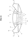
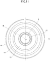
- FIGS. 10 and 11 are examples of a speaker unit that is made thin.
- FIG. 10 is a cross-sectional view of the speaker unit taken along line B-O-C in FIG. 11, and FIG. 11 is a top view of the speaker unit from which a dust cap shown in FIG. 10 is removed.
- a magnetic circuit 8 includes a bottomed cylindrical yoke 4 one end face of which is open, a disc-like magnet 7 provided on an inner bottom surface of the yoke 4, and a disc-shaped center pole 6 stacked on the magnet 7.
- a cylindrical portion of the yoke 4 has six slits 5 which are arranged at a pitch of 60 degrees along the circumferential direction and extend from an end of the open face toward the bottom.
- a gap is formed between outer peripheral surfaces of the magnet 7 and the center pole 6 and an inner peripheral surface of the cylindrical portion of the yoke 4, and a gap between the outer peripheral surface of the center pole 6 and the inner peripheral surface of the yoke 4 serves as a magnetic gap.
- a voice coil 3 arranged in the magnetic gap includes a cylindrical bobbin 1, and a coil 2 wound around a peripheral surface of the bobbin 1.
- a double ring 12 includes an outer ring 10 facing an outer peripheral surface of the yoke 4 with a gap interposed therebetween, an inner ring 9 connected to the bobbin 1 of the voice coil 3, and six joints 11 connecting the outer ring 10 and the inner ring 9.
- the joints 11 are arranged to correspond to the slits 5 of the magnetic circuit 8.
- An inner peripheral portion of a diaphragm 13 is connected to a lower portion of the outer ring 10 of the double ring 12.
- An outer peripheral portion of the diaphragm 13 is attached to a frame 16 via an edge portion 15.
- the double ring 12 and the voice coil 3 are movable in a non-contact manner with the yoke 4.
- a dust cap 17 that covers the bobbin 1 and the double ring 12 is arranged at a center portion of the diaphragm 13.
- a magnetic field is generated in the magnetic gap of the magnetic circuit 8.
- a voice signal is supplied to the coil 2 of the voice coil 3 arranged in the magnetic gap
- a driving force is generated in the voice coil 3 due to the Fleming's left-hand rule, which vibrates the diaphragm 13, and sound is emitted.
- an inner peripheral surface of the diaphragm 13 is connected to the lower portion of the outer ring 10 of the double ring 12. This can make the speaker unit thin.
- Patent Document 1 Japanese Unexamined Patent Publication No. 2002-78082
- the speaker unit configured as shown in FIGS. 10 and 11 can be made thin, the double ring 12 is still necessary, and the following problems arise.
- the present invention has been achieved in view of the above problems, and an object of the present invention is to provide a speaker unit which is low in cost, good in sound quality, and can be made thin.
- a speaker unit according to claim 1 of the present invention that achieves the object includes:
- the speaker unit of claim 1 of the present invention can provide the following advantages.
- FIG. 1 is an exploded perspective view illustrating a speaker unit according to a first embodiment of the present invention.
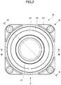
- FIG. 2 is a front view illustrating the components shown in FIG. 1 in an assembled state.
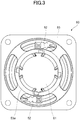
- FIG. 3 is a rear view of the assembly of FIG. 2 .
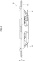
- FIG. 4 is a view taken in a direction of arrow IV of FIG. 2 .
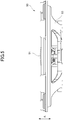
- FIG. 5 is a cross-sectional view taken in a direction of arrow V in FIG. 2 .
- FIG. 6 is a cross-sectional view taken along line VI-VI in FIG. 2 .
- FIG. 7 is a cross-sectional view taken along line VII-VII in FIG. 2 .
- An outer peripheral portion 51b of a diaphragm 51 is attached to a frame 53 via an edge portion 55.
- the diaphragm 51 is shaped to be recessed at a center thereof from the outer peripheral portion 51b to an inner peripheral portion 51c, and has a round center hole 51a that penetrates the center (inner peripheral portion 51c) of the diaphragm 51 in a thickness direction thereof.
- the frame 53 is shaped to be recessed in the same direction as the diaphragm 51 is recessed, and has a bottom 53a at a center thereof.
- a hole 53b is formed to penetrate the bottom 53a in a thickness direction thereof.
- a magnetic circuit 61 is provided on the bottom 53a of the frame 53.
- the magnetic circuit 61 includes a yoke 63, a magnet 65, and a pole piece 66.
- the yoke 63 is a bottomed cylindrical member made of a soft magnetic material, one of end faces of which is open.
- the yoke 63 has a base portion 67 mounted in the hole 53b at the bottom 53a of the frame 53, and a cylindrical portion 69 that extends from a peripheral edge of the base portion 67 in a direction away from the bottom 53a of the frame 53 along a vibration direction of the diaphragm 51 (a direction of arrows A in FIGS. 1 and 4 to 7 ) and functions as an outer cylindrical portion of the magnetic circuit 61 (see FIG. 6 ). That is, the cylindrical portion 69 is an outer cylindrical portion according to the present invention.
- the cylindrical portion 69 is provided with a plurality of standing walls 69c extending from an end of the open end face of the cylindrical portion 69 to the base portion 67 along the vibration direction of the diaphragm 51 (the direction of arrows A), and a plurality of slits 69a.
- the slits 69a of the present embodiment includes four slits 69a arranged at a pitch of 90° along a circumferential direction of the cylindrical portion 69.
- the cylindrical portion 69 includes the four slits 69a and four standing walls 69c divided by the four slits 69a.
- the base portion 67 is provided with four mounting portions 67a extending outward to correspond to the slits 69a.
- the four mounting portions 67a are fitted into four mounting recesses 53c formed in the periphery of the hole 53b of the frame 53, thereby positioning the magnetic circuit 61 with respect to the frame 53.
- the magnet 65 is formed in a disc shape, and placed on the base portion 67 of the yoke 63.
- the magnet 65 is magnetized in the vibration direction of the diaphragm 51 (the direction of arrows A).
- a disc-shaped pole piece 66 made of a soft magnetic material is placed on the magnet 65.
- an annular space is formed between an inner peripheral surface of the cylindrical portion 69 of the yoke 63 and an outer peripheral surface of the pole piece 66.
- This annular space serves as a magnetic gap G in which a substantially uniform magnetic field is generated in the circumferential direction.
- the inner peripheral portion 51c of the diaphragm 51 is provided with four insert holes 57 in each of which an associated one of the standing walls 69c of the yoke 63 of the magnetic circuit 61 is inserted, and four insert portions 59 each of which is inserted into an associated one of the slits 69a of the yoke 63 of the magnetic circuit 61.
- the insert holes 57 and the insert portions 59 are alternately arranged in the circumferential direction.
- the insert holes 57 penetrate the diaphragm 51 in the vibration direction (thickness direction).
- Each insert hole 57 serves as a standing wall receiving portion of the present invention.
- the inner peripheral portion 51c of the diaphragm 51 includes a ring-shaped inner annular portion 591 formed inward of the insert holes 57 in a radial direction of the diaphragm 51, and a ring-shaped outer annular portion 592 formed outward of the insert holes 57 in the radial direction of the diaphragm 51. Accordingly, the insert holes 57 are formed between the inner annular portion 591 and the outer annular portion 592.
- the center hole 51a of the diaphragm 51 is formed by an inner peripheral surface of the inner annular portion 591 (an inner peripheral surface of the inner peripheral portion 51c).
- the inner peripheral surface of the inner annular portion 591 is connected to a voice coil 85.
- the insert hole 57 of the diaphragm 51 serving as the standing wall receiving portion of the diaphragm 51 may be replaced with a notch formed to open in an inner peripheral surface of the center hole 51a of the diaphragm 51.
- an inner peripheral surface of each insert portion 59 may be connected to the voice coil 85 without forming the inner annular portion 591.
- the voice coil 85 includes a cylindrical bobbin 81 arranged between an inner peripheral surface of the cylindrical portion 69 (the standing walls 69c) of the yoke 63 and outer peripheral surfaces of the magnet 65 and the pole piece 66, and a coil 83 wound around an outer peripheral surface of the bobbin 81.
- the bobbin 81 and the inner peripheral surface of the center hole 51a of the diaphragm 51 are connected to each other so that the coil 83 is positioned in the magnetic gap G of the magnetic circuit 61.
- the inner peripheral surface of the inner peripheral portion 51c of the diaphragm 51 (the inner peripheral surface of the inner annular portion 591) is connected to the voice coil 85 via the slits 69a of the yoke 63 of the magnetic circuit 61.
- the inner peripheral surface of the center hole 51a of the diaphragm 51 (the inner peripheral surface of the inner peripheral portion 51c of the diaphragm 51) is connected to a lower portion of the bobbin 81.
- the inner peripheral surface of the center hole 51a of the diaphragm 51 (the inner peripheral surface of the inner peripheral portion 51c of the diaphragm 51) is connected to an outer peripheral surface of the bobbin 81 near the base portion 67 of the yoke 63, i.e., the outer peripheral surface of the bobbin 81 below the coil 83.
- the outer and inner peripheral portions 51b and 51c of the diaphragm 51 are integrated with each other.
- the inner peripheral portion 51c of the diaphragm 51 is greater in thickness (thicker) than the outer peripheral portion 51b.
- the inner peripheral portion 51c of the diaphragm 51 is shaped to gradually decrease in diameter toward the lower side in the vibration direction (the direction of arrows A), and the inner annular portion 591 is arranged below the outer annular portion 592 in the vibration direction (the direction of arrows A) in the inner peripheral portion 51c of the diaphragm 51.
- the surface of the diaphragm 51 and the surface of the bobbin 81 bonded to each other has a dimension (t1) which is larger than (thicker than) the thickness (t2) of the outer peripheral portion 51b.
- a dust cap 91 constituting part of the diaphragm 51 is used to keep dust or the like from entering the speaker unit from the center hole 51a of the diaphragm 51.
- the dust cap 91 includes a dome portion 91c which is in the shape of a dome that covers the opening of the bobbin 81, a diaphragm connecting portion 91a which is connected to the diaphragm 51, and a voice coil connecting portion 91b which is connected to the voice coil 85.
- the diaphragm connecting portion 91a is an outermost peripheral portion of the dust cap 91, and covers the inner peripheral portion 51c of the diaphragm 51 from above.
- the voice coil connecting portion 91b is a portion formed radially inward of the diaphragm connecting portion 91a.
- the voice coil connecting portion 91b of the dust cap 91 is connected to the outer peripheral surface of the bobbin 81 (an upper portion of the bobbin 81) located above the coil 83 of the voice coil 85.
- an outer peripheral edge of the diaphragm connecting portion 91a of the dust cap 91 is connected to an outer periphery of the inner peripheral portion 51c near the boundary between the inner and outer peripheral portions 51c and 51b of the diaphragm 51.
- the inner peripheral surface of the center hole 51a of the diaphragm 51 (the inner peripheral surface of the inner annular portion 591) is connected to the outer peripheral surface of the bobbin 81 below the coil 83.
- the inner peripheral surface of the inner peripheral portion 51c of the diaphragm 51 is connected to the lower portion of the bobbin 81; the outer periphery of the inner peripheral portion 51c is connected to the outer peripheral edge of the diaphragm connecting portion 91a of the dust cap 91; and the voice coil connecting portion 91b of the dust cap 91 is connected to the upper portion of the bobbin 81.
- the frame 53 is provided with a terminal 52.
- the terminal 52 and the coil 83 of the voice coil 85 are electrically connected to each other by a tinsel wire (lead wire) which is not shown.
- An electric signal inputted to the terminal 52 flows through the coil 83 of the voice coil 85 via the tinsel wire.
- the coil 83 is arranged in the magnetic field generated by the magnetic circuit 61.
- the diaphragm 51 is driven by the driving force generated in the coil 83 (the voice coil 85) and vibrates in the directions of arrows A, and sound is emitted.
- the first embodiment has been directed to the speaker unit 50 having no damper for supporting the voice coil.
- the speaker unit may further include a damper for supporting the voice coil.
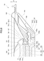
- FIG. 8 is a half cross-sectional view of a speaker unit 150 according to a second embodiment of the present invention
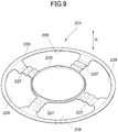
- FIG. 9 is a perspective view illustrating a damper 201 shown in FIG. 8 .
- An outer peripheral portion 151b of a diaphragm 151 is attached to a frame 153 via an edge portion 155.
- the diaphragm 151 is shaped to be recessed at a center thereof from the outer peripheral portion 151b to an inner peripheral portion 151c, and has a round center hole 151a that penetrates the center (inner peripheral portion 151c) of the diaphragm 151 in a thickness direction thereof.
- the frame 153 is shaped to be recessed in the same direction as the diaphragm 151 is recessed, and has a bottom 153a at a center thereof.
- a hole 153b is formed to penetrate the bottom 153a in a thickness direction thereof.
- a magnetic circuit 161 is provided on the bottom 153a of the frame 153.
- the magnetic circuit 161 includes a yoke 163, a magnet 165, and a pole piece 166.
- the yoke 163 is a bottomed cylindrical member made of a soft magnetic material, one of end faces of which is open.
- the yoke 163 has a base portion 167 mounted in the hole 153b at the bottom 153a of the frame 153, and a cylindrical portion 169 that extends from a peripheral edge of the base portion 167 in a direction away from the bottom 153a of the frame 153 along a vibration direction of the diaphragm 151 (a direction of arrows A' in FIG. 8 ) and functions as an outer cylindrical portion of the magnetic circuit 161. That is, the cylindrical portion 169 is an outer cylindrical portion according to the present invention.
- the cylindrical portion 169 is provided with a plurality of standing walls 169c extending from an end of the open end face of the cylindrical portion 169 to the base portion 167 along the vibration direction of the diaphragm 151 (the direction of arrows A'), and a plurality of slits 169a.
- the slits 169a of the present embodiment includes four slits 169a arranged at a pitch of 90° along a circumferential direction of the cylindrical portion 169.
- the cylindrical portion 169 includes four slits 169a and four standing walls 169c divided by the four slits 169a.
- the magnet 165 is formed in a disc shape, and placed on the base portion 167 of the yoke 163.
- the magnet 165 is magnetized in the vibration direction of the diaphragm 151 (the direction of arrows A').
- a disc-shaped pole piece 166 made of a soft magnetic material is placed on the magnet 165.
- an annular space is formed between an inner peripheral surface of the cylindrical portion 169 of the yoke 163 and an outer peripheral surface of the pole piece 166.
- This annular space serves as a magnetic gap G' in which a substantially uniform magnetic field is generated in the circumferential direction.
- the diaphragm 151 has the same shape as the diaphragm 51 of the first embodiment.
- the inner peripheral portion 151c of the diaphragm 151 is provided with four insert holes (standing wall receiving portions) 157 in each of which an associated one of the standing walls 169c of the yoke 163 of the magnetic circuit 161 is inserted, and four insert portions 159 each of which is inserted in an associated one of the slits 169a of the yoke 163 of the magnetic circuit 161.
- the insert holes 157 and the insert portions 159 are alternately arranged in the circumferential direction.
- the insert holes 157 penetrate the diaphragm 151 in the vibration direction (thickness direction).
- a voice coil 185 includes a cylindrical bobbin 181 arranged between an inner peripheral surface of the cylindrical portion 169 (the standing walls 169c) of the yoke 163 and outer peripheral surfaces of the magnet 165 and the pole piece 166, and a coil 183 wound around an outer peripheral surface of the bobbin 181.
- the bobbin 181 and the inner peripheral surface of the center hole 151a of the diaphragm 151 are connected to each other so that the coil 183 is positioned in the magnetic gap G' of the magnetic circuit 161. That is, the inner peripheral surface of the inner peripheral portion 151c of the diaphragm 151 is connected to the voice coil 185 via the slits 169a of the yoke 163 of the magnetic circuit 161.
- the inner peripheral surface of the center hole 151a of the diaphragm 151 (the inner peripheral surface of the inner peripheral portion 151c of the diaphragm 151) is connected to a lower portion of the bobbin 181.
- the inner peripheral surface of the center hole 151a of the diaphragm 151 (the inner peripheral surface of the inner peripheral portion 151c of the diaphragm 151) is connected to an outer peripheral surface of the bobbin 181 near the base portion 167 of the yoke 163, i.e., the outer peripheral surface of the bobbin 181 below the coil 183.
- the outer and inner peripheral portions 151b and 151c of the diaphragm 151 are integrated with each other.
- the inner peripheral portion 151c of the diaphragm 151 is greater in thickness (thicker) than the outer peripheral portion 151b.
- a dust cap 191 constituting part of the diaphragm 151 is used to keep dust or the like from entering the speaker unit from center hole 151a of the diaphragm 151.
- the dust cap 191 includes a dome portion 191c which is in the shape of a dome that covers the opening of the bobbin 181, a diaphragm connecting portion 191a which is connected to the diaphragm 151, and a voice coil connecting portion 191b which is connected to the voice coil 185.
- the diaphragm connecting portion 191a is an outermost peripheral portion of the dust cap 191, and covers the inner peripheral portion 151c of the diaphragm 151 from above.
- the voice coil connecting portion 191b is a portion formed radially inward of the diaphragm connecting portion 191a.
- the voice coil connecting portion 191b of the dust cap 191 is connected to the outer peripheral surface of the bobbin 181 (an upper portion of the bobbin 181) located above the coil 183 of the voice coil 185.
- an outer peripheral edge of the diaphragm connecting portion 191a of the dust cap 191 is connected to an outer periphery of the inner peripheral portion 151c near the boundary between the inner and outer peripheral portions 151c and 151b of the diaphragm 151.
- the inner peripheral surface of the center hole 151a of the diaphragm 151 is connected to the outer peripheral surface of the bobbin 181 below the coil 183.
- the inner peripheral surface of the inner peripheral portion 151c of the diaphragm 151 is connected to the lower portion of the bobbin 181; the outer periphery of the inner peripheral portion 151c is connected to the outer peripheral edge of the diaphragm connecting portion 191a of the dust cap 191; and the voice coil connecting portion 191b of the dust cap 191 is connected to the upper portion of the bobbin 181.
- a damper 201 supports the voice coil 185.
- the damper 201 includes an outer ring portion 203 connected to the frame 153, an inner ring portion 205 connected to the voice coil 185, bridge portions 207 that bridge over the outer ring portion 203 and the inner ring portion 205, and openings 209 each of which is surrounded by the outer ring portion 203, the inner ring portion 205, and the bridge portions 207.
- the outer ring portion 203 and the inner ring portion 205 are concentrically formed, and the inner ring portion 205 is arranged inside the outer ring portion 203.
- the outer ring portion 203 is connected to a lower portion of the frame 153, i.e., connected to the frame 153 below the edge portion 155.
- the inner ring portion 205 is connected to a portion of the bobbin 181 of the voice coil 185 below a junction between the bobbin 181 and the diaphragm 151.
- Each bridge portion 207 extends in a radial direction of the outer ring portion 203, and bridges over the outer ring portion 203 and the inner ring portion 205.
- the damper 201 has four bridge portions 207.
- the openings 209 penetrate the diaphragm 151 in the vibration direction (the thickness direction of the damper 201), and include four openings 209, equal to the number of bridge portions 207.
- the number of bridge portions 207 and openings 209 is not limited to four, and may be any other number.
- Each bridge portion 207 is inserted into an associated one of the slits 169a of the yoke 163 of the magnetic circuit 161.
- the bridge portion 207 is corrugated when viewed in section taken along the radial direction.
- the voice coil 185 supported by the damper 201 can move in the direction of arrows A'.
- an associated one of the standing walls 169c of the yoke 163 of the magnetic circuit 161 is inserted.
- An electric signal flows through the coil 183 of the voice coil 185.
- the coil 183 is arranged in the magnetic field generated by the magnetic circuit 161.
- the diaphragm 151 is driven by the driving force generated in the coil 183 (the voice coil 185) and vibrates in the direction of arrows A', and sound is emitted.
Landscapes
- Engineering & Computer Science (AREA)
- Physics & Mathematics (AREA)
- Acoustics & Sound (AREA)
- Signal Processing (AREA)
- Multimedia (AREA)
- Audible-Bandwidth Dynamoelectric Transducers Other Than Pickups (AREA)
Applications Claiming Priority (2)
| Application Number | Priority Date | Filing Date | Title |
|---|---|---|---|
| JP2017199021 | 2017-10-13 | ||
| PCT/JP2018/030983 WO2019073697A1 (fr) | 2017-10-13 | 2018-08-22 | Unité de haut-parleur |
Publications (2)
| Publication Number | Publication Date |
|---|---|
| EP3697105A1 true EP3697105A1 (fr) | 2020-08-19 |
| EP3697105A4 EP3697105A4 (fr) | 2020-12-09 |
Family
ID=66101419
Family Applications (1)
| Application Number | Title | Priority Date | Filing Date |
|---|---|---|---|
| EP18866099.7A Pending EP3697105A4 (fr) | 2017-10-13 | 2018-08-22 | Unité de haut-parleur |
Country Status (5)
| Country | Link |
|---|---|
| US (1) | US11284198B2 (fr) |
| EP (1) | EP3697105A4 (fr) |
| JP (1) | JP6990250B2 (fr) |
| CN (1) | CN111194560B (fr) |
| WO (1) | WO2019073697A1 (fr) |
Families Citing this family (2)
| Publication number | Priority date | Publication date | Assignee | Title |
|---|---|---|---|---|
| CN213462307U (zh) * | 2020-07-06 | 2021-06-15 | 瑞声科技(新加坡)有限公司 | 扬声器 |
| CN118317229A (zh) * | 2022-12-30 | 2024-07-09 | 迪芬尼香港有限公司 | 振膜组件、制造振膜组件的方法及射出成型的模具 |
Family Cites Families (30)
| Publication number | Priority date | Publication date | Assignee | Title |
|---|---|---|---|---|
| JPS5856600A (ja) * | 1981-09-30 | 1983-04-04 | Hitachi Ltd | 平面形スピ−カ |
| JPS60155278A (ja) | 1983-11-21 | 1985-08-15 | Somar Corp | 粉体塗料用エポキシ樹脂組成物 |
| JPS61396U (ja) * | 1984-06-04 | 1986-01-06 | オンキヨー株式会社 | 平板型スピ−カ− |
| JPH01225299A (ja) * | 1988-03-04 | 1989-09-08 | Mitsubishi Electric Corp | コーンスピーカーの振動板結合装置 |
| DE3929266C1 (fr) * | 1989-09-02 | 1991-01-03 | Mercedes-Benz Aktiengesellschaft, 7000 Stuttgart, De | |
| JPH07154896A (ja) * | 1993-11-29 | 1995-06-16 | Matsushita Electric Ind Co Ltd | スピーカ |
| JP3260062B2 (ja) * | 1995-09-04 | 2002-02-25 | 株式会社ケンウッド | スピーカ |
| CN1179692A (zh) * | 1996-05-23 | 1998-04-22 | 日本先锋公司 | 扬声器 |
| JP3505037B2 (ja) * | 1996-05-23 | 2004-03-08 | パイオニア株式会社 | スピーカ |
| JPH09327087A (ja) * | 1996-06-06 | 1997-12-16 | Matsushita Electric Ind Co Ltd | ダブルコーンスピーカ |
| US6842529B2 (en) * | 2000-09-04 | 2005-01-11 | Matsushita Electric Industrial Co., Ltd. | Speaker |
| JP2002078082A (ja) | 2000-09-04 | 2002-03-15 | Matsushita Electric Ind Co Ltd | スピーカ |
| JP4557412B2 (ja) * | 2000-11-20 | 2010-10-06 | パナソニック株式会社 | スピーカ |
| US7209570B2 (en) * | 2001-06-11 | 2007-04-24 | Matsushita Electric Industrial Co., Ltd. | Speaker |
| US6968071B2 (en) * | 2003-01-15 | 2005-11-22 | Chao-Lang Wang | Speaker having magnetic member installed on diaphragm |
| JP3651470B2 (ja) * | 2003-03-31 | 2005-05-25 | 松下電器産業株式会社 | スピーカ |
| JP2005159506A (ja) * | 2003-11-21 | 2005-06-16 | Pioneer Electronic Corp | スピーカ装置 |
| JP4610890B2 (ja) * | 2003-12-24 | 2011-01-12 | パイオニア株式会社 | スピーカ装置 |
| JP2005252924A (ja) * | 2004-03-08 | 2005-09-15 | Matsushita Electric Ind Co Ltd | スピーカ |
| CN200973173Y (zh) | 2006-11-16 | 2007-11-07 | 常州美欧电子有限公司 | 振动发声器 |
| CN200997173Y (zh) | 2006-12-05 | 2007-12-26 | 哈尔滨自动化仪表研究所 | 供热温度检测仪 |
| JP2011004308A (ja) * | 2009-06-22 | 2011-01-06 | Foster Electric Co Ltd | スピーカ装置 |
| JP5190033B2 (ja) * | 2009-07-03 | 2013-04-24 | ホシデン株式会社 | 振動センサ |
| CN101626535B (zh) * | 2009-08-17 | 2014-06-18 | 瑞声声学科技(深圳)有限公司 | 发声器 |
| CN102932716A (zh) * | 2011-08-08 | 2013-02-13 | 美隆工业股份有限公司 | 内支架喇叭结构 |
| US9078059B2 (en) | 2012-08-07 | 2015-07-07 | Jabil Circuit (Beijing), Ltd. | Transducer |
| CN103118320B (zh) * | 2013-01-18 | 2015-11-11 | 歌尔声学股份有限公司 | 一种超薄扬声器模组 |
| CN104822115B (zh) * | 2015-05-08 | 2018-11-02 | 歌尔股份有限公司 | 一种扬声器装置 |
| JPWO2017149984A1 (ja) * | 2016-02-29 | 2018-12-20 | パナソニックIpマネジメント株式会社 | スピーカ |
| JP2020114308A (ja) | 2019-01-18 | 2020-07-30 | 株式会社三共 | 遊技機 |
-
2018
- 2018-08-22 WO PCT/JP2018/030983 patent/WO2019073697A1/fr not_active Ceased
- 2018-08-22 US US16/755,622 patent/US11284198B2/en active Active
- 2018-08-22 JP JP2019547935A patent/JP6990250B2/ja active Active
- 2018-08-22 EP EP18866099.7A patent/EP3697105A4/fr active Pending
- 2018-08-22 CN CN201880065429.5A patent/CN111194560B/zh active Active
Also Published As
| Publication number | Publication date |
|---|---|
| EP3697105A4 (fr) | 2020-12-09 |
| JPWO2019073697A1 (ja) | 2020-10-22 |
| CN111194560B (zh) | 2022-02-22 |
| JP6990250B2 (ja) | 2022-01-12 |
| US20200336838A1 (en) | 2020-10-22 |
| WO2019073697A1 (fr) | 2019-04-18 |
| CN111194560A (zh) | 2020-05-22 |
| US11284198B2 (en) | 2022-03-22 |
Similar Documents
| Publication | Publication Date | Title |
|---|---|---|
| EP2262281B1 (fr) | Haut-parleur | |
| EP2131606B1 (fr) | Haut-parleur | |
| US8290199B2 (en) | Loudspeaker suspension | |
| EP2512155B1 (fr) | Transducteur de haut-parleur à profil bas | |
| CN107079221B (zh) | 电声变换器 | |
| EP2512154B1 (fr) | Aimant de haut-parleur doté d'un canal | |
| EP2512153B1 (fr) | Ensemble d'aimant de haut-parleur | |
| WO2002021880A1 (fr) | Haut-parleur | |
| EP3697105A1 (fr) | Unité de haut-parleur | |
| EP2512156B1 (fr) | Haut-parleur à profil bas | |
| US20080285787A1 (en) | Thin loudspeaker | |
| CN115769600B (zh) | 电声换能器 | |
| US9398375B2 (en) | Electrodynamic electroacoustic transducer, diaphragm thereof, and method of manufacturing the same | |
| JP2019106580A (ja) | 加振器およびこれを構成する弾性連結部材 | |
| KR102085840B1 (ko) | 음향 변환 장치 | |
| JP2002078082A (ja) | スピーカ | |
| JPWO2009063567A1 (ja) | スピーカ装置 | |
| JP4592382B2 (ja) | スピーカ | |
| JP2005295354A (ja) | 振動板、その製造方法、および、スピーカ装置 | |
| JP2001016687A (ja) | スピーカ用キャップ一体型ダンパ | |
| WO2016158285A1 (fr) | Dispositif de production de son | |
| JP2017169006A (ja) | 電気音響変換器 | |
| JP2013157691A (ja) | 薄型スピーカ |
Legal Events
| Date | Code | Title | Description |
|---|---|---|---|
| STAA | Information on the status of an ep patent application or granted ep patent |
Free format text: STATUS: THE INTERNATIONAL PUBLICATION HAS BEEN MADE |
|
| PUAI | Public reference made under article 153(3) epc to a published international application that has entered the european phase |
Free format text: ORIGINAL CODE: 0009012 |
|
| STAA | Information on the status of an ep patent application or granted ep patent |
Free format text: STATUS: REQUEST FOR EXAMINATION WAS MADE |
|
| 17P | Request for examination filed |
Effective date: 20200504 |
|
| AK | Designated contracting states |
Kind code of ref document: A1 Designated state(s): AL AT BE BG CH CY CZ DE DK EE ES FI FR GB GR HR HU IE IS IT LI LT LU LV MC MK MT NL NO PL PT RO RS SE SI SK SM TR |
|
| AX | Request for extension of the european patent |
Extension state: BA ME |
|
| A4 | Supplementary search report drawn up and despatched |
Effective date: 20201105 |
|
| RIC1 | Information provided on ipc code assigned before grant |
Ipc: H04R 7/12 20060101ALI20201030BHEP Ipc: H04R 9/04 20060101ALI20201030BHEP Ipc: H04R 9/02 20060101AFI20201030BHEP |
|
| DAV | Request for validation of the european patent (deleted) | ||
| DAX | Request for extension of the european patent (deleted) | ||
| STAA | Information on the status of an ep patent application or granted ep patent |
Free format text: STATUS: EXAMINATION IS IN PROGRESS |
|
| 17Q | First examination report despatched |
Effective date: 20220531 |
|
| GRAP | Despatch of communication of intention to grant a patent |
Free format text: ORIGINAL CODE: EPIDOSNIGR1 |
|
| STAA | Information on the status of an ep patent application or granted ep patent |
Free format text: STATUS: GRANT OF PATENT IS INTENDED |