EP3697177B1 - Capteur tactile pourvu de conduit de lumière intégré - Google Patents
Capteur tactile pourvu de conduit de lumière intégré Download PDFInfo
- Publication number
- EP3697177B1 EP3697177B1 EP19157220.5A EP19157220A EP3697177B1 EP 3697177 B1 EP3697177 B1 EP 3697177B1 EP 19157220 A EP19157220 A EP 19157220A EP 3697177 B1 EP3697177 B1 EP 3697177B1
- Authority
- EP
- European Patent Office
- Prior art keywords
- light
- light guide
- coupled
- rocker
- tactile sensor
- Prior art date
- Legal status (The legal status is an assumption and is not a legal conclusion. Google has not performed a legal analysis and makes no representation as to the accuracy of the status listed.)
- Active
Links
Images



Classifications
-
- H—ELECTRICITY
- H01—ELECTRIC ELEMENTS
- H01H—ELECTRIC SWITCHES; RELAYS; SELECTORS; EMERGENCY PROTECTIVE DEVICES
- H01H23/00—Tumbler or rocker switches, i.e. switches characterised by being operated by rocking an operating member in the form of a rocker button
- H01H23/02—Details
- H01H23/025—Light-emitting indicators
-
- H—ELECTRICITY
- H05—ELECTRIC TECHNIQUES NOT OTHERWISE PROVIDED FOR
- H05B—ELECTRIC HEATING; ELECTRIC LIGHT SOURCES NOT OTHERWISE PROVIDED FOR; CIRCUIT ARRANGEMENTS FOR ELECTRIC LIGHT SOURCES, IN GENERAL
- H05B45/00—Circuit arrangements for operating light-emitting diodes [LED]
- H05B45/20—Controlling the colour of the light
-
- H—ELECTRICITY
- H01—ELECTRIC ELEMENTS
- H01H—ELECTRIC SWITCHES; RELAYS; SELECTORS; EMERGENCY PROTECTIVE DEVICES
- H01H2219/00—Legends
- H01H2219/036—Light emitting elements
- H01H2219/039—Selective or different modes of illumination
-
- H—ELECTRICITY
- H01—ELECTRIC ELEMENTS
- H01H—ELECTRIC SWITCHES; RELAYS; SELECTORS; EMERGENCY PROTECTIVE DEVICES
- H01H2219/00—Legends
- H01H2219/036—Light emitting elements
- H01H2219/044—Edge lighting of layer
-
- H—ELECTRICITY
- H01—ELECTRIC ELEMENTS
- H01H—ELECTRIC SWITCHES; RELAYS; SELECTORS; EMERGENCY PROTECTIVE DEVICES
- H01H2219/00—Legends
- H01H2219/054—Optical elements
- H01H2219/06—Reflector
-
- H—ELECTRICITY
- H01—ELECTRIC ELEMENTS
- H01H—ELECTRIC SWITCHES; RELAYS; SELECTORS; EMERGENCY PROTECTIVE DEVICES
- H01H2219/00—Legends
- H01H2219/054—Optical elements
- H01H2219/062—Light conductor
Definitions
- the invention is based on a push button sensor with a circuit board carrier for surface mounting, a circuit board mounted on the circuit board carrier on which at least one switching element and at least two light sources are arranged, and with at least one operating rocker for actuating the switching element, the operating rocker having at least one Has light guide, via which light generated by the light sources is guided to a control surface of the rocker switch.
- a push button sensor is from the DE 20 2008 015 052 U1 known.
- Other devices are known from EP 2 461 238 A2 , EP 1 005 055 A2 , EP 3 407 369 A1 such as US 2006/201796 A1 .
- Such touch sensors often have several of the light guides described above, for example to indicate different switching states.
- White light diodes are sometimes used as light sources, which due to manufacturing tolerances, however, emit a light spectrum that varies from diode to diode, so that with the touch sensors known from the prior art there can be color differences between the spectrum of the light sources of the touch sensor, which is sufficient aesthetic reasons is undesirable.
- the touch sensors known from the prior art have the disadvantage that the color spectrum emitted by the light sources can only be varied to a limited extent. However, if, for example, an RGB diode is used as the light source instead of a white light diode, it is often impossible to generate satisfactory white light.
- the light guide has a first light entry face and a second light entry face separated from the first light entry face, light generated by a first of the light sources being coupled into the light guide through the first light entry face, and light generated by a second of the light sources through the second light entry surface is coupled into the light guide, with a first reflector of the first light entry surface of the light guide and a second reflector in front of the second light entry surface for light coupling into the light guide, and each of the two reflectors being a reflective boundary wall of a separate light mixing chamber, the a first of the light sources generated light is coupled into a first of the two separate light mixing chambers and the light generated by a second of the light sources is coupled into a second of the two separate light mixing chambers, with between hen the circuit board and the at least one rocker switch, a rocker mount is arranged to which the at least one rocker switch is pivotably attached.
- a light guide that is designed for the coupling of at least two light sources, which can be designed as different light sources, it is possible on the one hand to expand the light spectrum that can be generated and, on the other hand, to precisely generate one via the light guide by mutually coordinating the light sources with one another To realize control surface guided spectrum of the mixed light of both light sources.
- the mixed light from both light sources can emerge on the control surface via a common light exit surface.
- the light source is an RGB diode
- the light spectrum emitted by the RGB diode it is expedient for the light spectrum emitted by the RGB diode to be mixed before it enters the light guide in order to homogenize the spectrum.
- the light mixing chamber can have further reflectors or light-mixing means, for example materials that scatter the light, such as reflective microparticles.
- the light mixing chamber can enclose the light source, the light of which is coupled into the light mixing chamber, with an opening via which the light is coupled into the light mixing chamber, in particular radiated into it.
- At least one of the light sources can have a plurality of partial light sources which differ from one another with regard to the spectrum of their respective emitted light.
- the light source can be an RGB diode, for example.
- the two light entry surfaces can each be perpendicular to a light exit surface which is arranged in the operating surface of the rocker switch or at least parallel thereto.
- Both the light coupled into the light guide via the first light entry surface and also the light coupled into the light guide via the second light entry surface can be coupled out of the light guide via the same light exit surface.
- the light coupled into the light guide via the first light entry surface and the light coupled into the light guide via the second light entry surface can be decoupled from the light guide as mixed light after multiple reflections within the light guide.
- a rocker mount to which the at least one control rocker is pivotably attached, can be arranged between the board and the at least one operating rocker.
- the first and the second reflector and / or a respective light mixing chamber can each extend through the rocker mount up to the respectively assigned light source. It can be provided that at least one of the light sources protrudes into the respectively assigned light mixing chamber. Alternatively, the light source can be directly upstream of the light mixing chamber, in particular the opening of the light mixing chamber.
- a reflector of the light mixing chamber can be designed as a parabolic mirror, the light source being arranged at the focal point of the parabolic mirror.
- the light guide can be arranged on the edge of the rocker switch and have a first light exit surface, which is arranged in the rocker control surface or at least parallel to it, and a second light exit surface, which is arranged perpendicular to the first light exit surface and on the outer circumference of the rocker switch.
- the first and the second light exit surface can be formed in one piece and in particular merge without interruption at an edge of the rocker switch, thereby ensuring that the pushbutton sensor can be easily recognized in the dark, even from the side.
- the rocker switch can have a cutout, preferably a substantially U-shaped cutout, into which the light guide is inserted.
- a light exit surface of the light guide can in turn be arranged in the operating surface of the operating rocker or at least parallel thereto.
- One of the two light sources can be a white light source, preferably a white light-emitting diode, and the other a light source with an adjustable emission spectrum, preferably an RGB light-emitting diode.
- the light guide can consist of a plastic or glass with embedded reflective microparticles, at least in the beam path of the coupled light, in order to improve the mixing of the light spectra of the light sources.
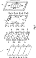
- the Figure 1 shows a first embodiment of a touch sensor 1 according to the invention.
- This has a circuit board carrier 2 for receiving a circuit board 3, the circuit board 3 having four arrangements of a switching element 4 and each associated with a first light source 5.1 and a second light source 5.2 on opposite longitudinal edges at regular intervals.
- the two light sources 5.1, 5.2 can differ in at least one property, in particular with regard to the light spectrum they emit.
- the first light source 5.1 can be a white light LED
- the second light source 5.2 is an RGB LED.
- the arrangements, each comprising a switching element 4 and two light sources 5.1, 5.2 are arranged opposite one another in pairs. In total, eight of the previously described arrangements are provided on the circuit board 3 opposite one another in pairs, with four arrangements each on each of two opposite edges of the circuit board.
- a rocker mount 14 covers the board 3, so that the board 3 is arranged between the board carrier 2 and the rocker mount 14.
- the rocker carrier 14 has reset elements 23 opposite one another in relation to the pivot axis 24.
- the switching elements 4 can be operated individually by pivoting the operating rockers 6 about the pivot axis 24 via openings 27 through the rocker mount 14.
- the light emitted by the light sources 5.1, 5.2 can also are coupled through the openings 27 into the light guides 7 arranged in the rocker switches 6.
- the rocker switch 6 is designed in four parts, therefore four rocker switches 6 that can be operated separately are provided; each of the four rocker switches 6 can be pivoted around the pivot axis 24 independently of the other rocker switches 6 in order to activate one of the switching elements 4 opposite in pairs.
- the four-part rocker switch 6 has a light guide 7 on each of its four subsegments on opposite edges of the respective subsegment, via which light from respectively assigned light sources 5.1, 5.2 is guided to the control surface 8 of the rocker switch 6 and to the side edge of the rocker switch 6.
- the operating rockers 6 can therefore be clearly identified both in the front view and in the side view in the dark.
- status information can be displayed about a light color or intensity of the light emitted via the light guide 7, for example about a switching status of an actuator of a building automation system.
- FIG. 2 an exemplary embodiment of a rocker switch 6 is shown.
- it can be one of the four subsegments of the rocker switch 6 according to FIG Figure 1 act.
- the rocker switch 6 consists essentially of a decorative part 25 which is fixed on a lower part 19 via an adhesion promoter 18, for example an adhesive film.
- the lower part 19 has a locking receptacle 21 in the center in the longitudinal direction for receiving a pivot axis, around which the operating rocker 6 for actuating the switching elements 4 (see Fig. Figure 1 ) is pivotable.
- the lower part 19 has a receptacle 20 for receiving a light guide 7.
- the receptacles 20 are open towards the decorative part 25, so that when the decorative part 25 is fixed on the lower part 19, the light guides 7 are fixed in the receptacles 20.
- the light guides 7 each have 2 light entry surfaces 9, one of which is used for coupling the light from one of the two light sources 5.1, 5.2 (see FIG. Figure 1 ) is provided.
- the light guide 7 also has a mounting web 22 over which the light guide 7 is locked in the receptacle 20.
- the light guide 7 also has a first light exit surface 13, which is aligned with the control surface 8 of the decorative part 25, and a second light exit surface 15, which is perpendicular to the first light exit surface 13 and is aligned with an outer circumference of the rocker switch 6.
- the two light exit surfaces 13, 15 merge into one another in one piece.
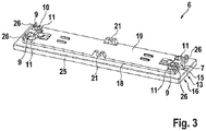
- FIG 3 is the in Figure 2 Control rocker 6 shown from the rear.
- a light mixing chamber 11 is located in front of each light guide 7 of each of the two light entry surfaces 9.
- the light mixing chamber 11 is provided to mix the light emitted by the light source 5, for example an RGB LED, which is respectively assigned to the light mixing chamber 11, before it is coupled into the light guide 7 via the light entry surface 9.
- the light mixing chamber 11 thus serves to further homogenize the spectrum of the light coupled into the light guide.
- a first of the two light mixing chambers 11 can be assigned an RGB LED, while the second light mixing chamber 11 is assigned a white light LED.
- the rocker switch 6 has, at its opposite ends, a light guide 7, the respective light entry surfaces 9 of which are assigned to separate light mixing chambers 11.
- a separate light source is assigned to each of the light mixing chambers 11, wherein at least one of the light sources, as already mentioned, can in turn be a light source composed of several partial light sources, for example an RGB LED.
- the lower part 19 has two locking pieces 26 associated with the light guides 7, by means of which the operating rocker 6 can be locked in the longitudinal direction of the operating rocker 6, with corresponding receptacles for the locking pieces 26 on the rocker mount 14 (see Fig. Figure 1 ) are designed in the manner of a slot in order to enable the rocker 6 to pivot about the pivot axis received in the latching receptacle 21.
- FIG. 4 a detailed view of a lower part 19 with light guides 7 received therein is shown from the underside, that is to say with a view of the side which faces the rocker mount 14 when the rocker switch 6 is mounted on the rocker mount 14.
- the light entry surfaces 9 of the light guide 7 are each enclosed by a light mixing chamber 11.
- the light mixing chamber 11 has a delimiting surface which is designed as a reflector 10. The light radiated into the light mixing chamber 11 is deflected by about 90 ° by the reflector and is coupled into the light guide 7 essentially perpendicular to the light entry surface 9.
- the light guide 7 has the two light exit surfaces 13, 15, which are aligned perpendicular to one another and which, as has already been described by way of example with reference to the previous figures, each with an outer side of a decorative part 25 (see Figure 3 ) the rocker switch 6 can be aligned.
- the light mixing chamber 11 is accessible on one side via an opening 12, via which light can be radiated into the light mixing chamber 11 from a respective light source 5.
- the light mixing chamber 11 and in particular its reflector 10 can be designed to effectively couple directional light, such as is generated, for example, by a light-emitting diode, via the light entry surfaces 9 into the light guide 7, i.e. to deflect the light in the light mixing chamber 11 in such a way that it preferably strikes the light entry surfaces 9 essentially perpendicularly.
- the Figure 5 shows the in Figure 4 The illustrated embodiment of a lower part 19 from the opposite side, that is to say from the side facing the decorative part 25.
- the receptacle 20, in which the light guide 7 is received in the lower part 19, is open on this side. Viewed from the end face of the lower part 19, the receptacle 20 is designed with an undercut, so that when the lower part 19 is glued to the decorative part 25, the light guide 7 is captively received in the receptacle 20.
- Latching pieces 26 are provided on the front side in order to lock the operating rocker 6 on the rocker receptacle 14 in the longitudinal direction of the operating rocker 6.
- the geometry of the light mixing chamber 11 in relation to the light inlet surface 9 of the light guide 7 and the positioning of the illuminant 5.1 in relation to the light mixing chamber 11 are shown using an exemplary embodiment.
- the lighting means 5.1 is a light-emitting diode, it radiates essentially perpendicularly into the light mixing chamber 11.
- a boundary wall 10 of the light mixing chamber 11 forms a reflector, via which the light radiated from the LED into the light mixing chamber 11 is coupled into the light guide 7 essentially perpendicular to the light entry surface 9.
- the reflector 10 can, for example, have the geometry of a parabolic mirror.
- different light colors can be generated via the two light mixing chambers 11 assigned to the light guide 7, for example by assigning a white LED to a first of the two light mixing chambers 11, while the second light mixing chamber 11 is assigned an RGB LED.
- the LEDs radiate vertically upwards, each into the separate light mixing chamber 11 assigned to it.
- the light mixing chamber 11 mixes and homogenizes, in particular, the light from the RGB LED and reflects it into the light guide 7.
- the light guide 7 can for example consist of light-scattering material, whereby the color mixing is further improved.
- the light can be deflected to the light exit surface 13 by internal reflections.
Landscapes
- Planar Illumination Modules (AREA)
- Switch Cases, Indication, And Locking (AREA)
Claims (12)
- Palpeur (1) avec un support de platine (2) pour un montage en surface, une platine (3) montée sur le support de platine (2), sur laquelle sont disposés au moins un élément de commutation (4) et au moins deux sources de lumière (5.1, 5.2), et avec au moins une bascule de commande (6) pour l'actionnement de l'élément de commutation (4), dans lequel l'au moins une bascule de commande (6) comprend au moins une fibre optique (7) par l'intermédiaire de laquelle la lumière générée par les sources de lumière (5.1, 5.2) est conduite vers une surface de commande (8) de la bascule de commande (6), caractérisé en ce que la fibre optique (7) comprend une première surface d'entrée de lumière (9) et une deuxième surface d'entrée de lumière (9) distincte de la première surface d'entrée de lumière (9), dans lequel la lumière générée par une première des sources de lumière (5.1, 5.2) est introduite à travers la première surface d'entrée de lumière (9) dans la fibre optique (7) et dans lequel la lumière générée par une deuxième des sources de lumière (5.1, 5.2) est introduite à travers la deuxième surface d'entrée de lumière (9) dans la fibre optique (7), dans lequel, pour l'introduction de la lumière dans la fibre optique (7), un premier réflecteur (10) est disposé en amont de la première surface d'entrée de lumière (9) et un deuxième réflecteur (10) est disposé en amont de la deuxième surface d'entrée de lumière (9), et dans lequel chacun des deux réflecteurs (10) est une paroi de limitation réfléchissante d'une chambre de mélange de lumière séparée (11), dans lequel la lumière générée par une première des sources de lumière (5.1, 5.2) est introduite dans une première des deux chambres de mélange de lumière séparées (11) et la lumière générée par une deuxième des sources de lumière (5.1, 5.2) est introduite dans une deuxième des deux chambres de mélange de lumière séparées (11), dans lequel, entre la platine (3) et l'au moins une bascule de commande (6), est disposé un logement de bascule (14) auquel l'au moins une bascule de commande (6) est fixée de manière pivotante.
- Palpeur (1) selon la revendication 1, dans lequel la chambre de mélange de lumière (11) entoure la source de lumière dont la lumière est introduite dans la chambre de mélange de lumière (11), avec une ouverture (12) par l'intermédiaire de laquelle la lumière est introduite dans la chambre de mélange de lumière (11).
- Palpeur (1) selon l'une des revendications précédentes, dans lequel au moins une des sources de lumière (5.1, 5.2) comprend plusieurs sources de lumière partielles (5.1, 5.2) qui se distinguent entre elles par le spectre de la lumière qu'elles émettent.
- Palpeur (1) selon l'une des revendications précédentes, dans lequel les deux surfaces d'entrée de lumière (9) sont chacune perpendiculaires à une surface de sortie de lumière (13) de la fibre optique (7), qui est disposée dans la surface de commande (8) de la bascule de commande (6) ou au moins parallèlement à celle-ci.
- Palpeur (1) selon la revendication 4, dans lequel aussi bien la lumière introduite par l'intermédiaire de la première surface d'entrée de lumière (9) que la lumière introduite par l'intermédiaire de la deuxième surface d'entrée de lumière (9) dans la fibre optique (7) est évacuée par l'intermédiaire de la même surface de sortie de lumière (13) hors de la fibre optique (7).
- Palpeur (1) selon la revendication 5, dans lequel la lumière introduite par l'intermédiaire de la première surface d'entrée de lumière (9) et la lumière introduite par l'intermédiaire de la deuxième surface d'entrée de lumière (9) dans la fibre optique (7) est évacuée hors de la fibre optique (7) après de multiples réflexions à l'intérieur de la fibre optique (7) sous la forme d'une lumière mélangée.
- Palpeur (1) selon l'une des revendications précédentes, dans lequel les premier et deuxième réflecteurs (10) et/ou une chambre de mélange de lumière (11) correspondante s'étend respectivement à travers le logement de bascule (14) jusqu'à la source de lumière (5.1, 5.2) correspondante.
- Palpeur (1) selon la revendication 4, dans lequel la fibre optique (7) est disposée sur le bord de la bascule de commande (6) et comprend la première surface de sortie de lumière (13), qui est disposée dans la surface de commande (8) de la bascule de commande (6) au moins parallèlement à celle-ci, et comprend une deuxième surface de sortie de lumière (15) qui est disposée perpendiculairement à la première surface de sortie de lumière (13) et sur la circonférence externe de la bascule de commande (6).
- Palpeur (1) selon la revendication 8, dans lequel les première et deuxième surfaces de sortie de lumière (13, 15) sont constituées d'une seule pièce et plus particulièrement présentent une transition l'une vers l'autre sans interruption au niveau d'une arête (16) de la bascule de commande (6).
- Palpeur (1) selon la revendication 1, dans lequel la bascule de commande (6) comprend, à partir de sa circonférence externe, une découpe (17), de préférence une découpe globalement en forme de U, dans laquelle la fibre optique (7) est insérée, dans lequel une surface de sortie de lumière (13) de la fibre optique (7) est disposée dans la surface de commande (8) de la bascule de commande (6) ou est au moins disposée parallèlement à celle-ci.
- Palpeur (1) selon l'une des revendications précédentes, dans lequel une des deux sources de lumière (5.1, 5.2) est une source de lumière blanche, de préférence une diode électroluminescente blanche et l'autre est une source de lumière à spectre d'émission réglable, de préférence une diode électroluminescente RVB.
- Palpeur (1) selon l'une des revendications précédentes, dans lequel la fibre optique (7) est constituée, au moins dans le trajet des faisceaux, d'une matière plastique ou de verre avec des microparticules réfléchissantes intégrées.
Priority Applications (1)
| Application Number | Priority Date | Filing Date | Title |
|---|---|---|---|
| EP19157220.5A EP3697177B1 (fr) | 2019-02-14 | 2019-02-14 | Capteur tactile pourvu de conduit de lumière intégré |
Applications Claiming Priority (1)
| Application Number | Priority Date | Filing Date | Title |
|---|---|---|---|
| EP19157220.5A EP3697177B1 (fr) | 2019-02-14 | 2019-02-14 | Capteur tactile pourvu de conduit de lumière intégré |
Publications (2)
| Publication Number | Publication Date |
|---|---|
| EP3697177A1 EP3697177A1 (fr) | 2020-08-19 |
| EP3697177B1 true EP3697177B1 (fr) | 2021-01-13 |
Family
ID=65493818
Family Applications (1)
| Application Number | Title | Priority Date | Filing Date |
|---|---|---|---|
| EP19157220.5A Active EP3697177B1 (fr) | 2019-02-14 | 2019-02-14 | Capteur tactile pourvu de conduit de lumière intégré |
Country Status (1)
| Country | Link |
|---|---|
| EP (1) | EP3697177B1 (fr) |
Families Citing this family (1)
| Publication number | Priority date | Publication date | Assignee | Title |
|---|---|---|---|---|
| AU2021429717A1 (en) | 2021-02-25 | 2023-08-17 | Razer (Asia-Pacific) Pte. Ltd. | Illumination panel device |
Family Cites Families (5)
| Publication number | Priority date | Publication date | Assignee | Title |
|---|---|---|---|---|
| IT1302883B1 (it) * | 1998-11-27 | 2000-10-10 | G & A Eng Srl | Pulsante luminoso con colorazione variabile elettronicamente. |
| DE202005003663U1 (de) * | 2005-03-08 | 2005-07-21 | Trw Automotive Electronics & Components Gmbh & Co. Kg | Elektrischer Tastschalter |
| EP2063511A2 (fr) * | 2007-11-26 | 2009-05-27 | Berker GmbH & Co KG | Appareil d'installation électrique/électronique |
| US9218115B2 (en) * | 2010-12-02 | 2015-12-22 | Lg Electronics Inc. | Input device and image display apparatus including the same |
| ES2780973T3 (es) * | 2017-05-24 | 2020-08-27 | Flex Automotive Gmbh | Dispositivo, sistema y procedimiento para la representación un símbolo de luz flotante |
-
2019
- 2019-02-14 EP EP19157220.5A patent/EP3697177B1/fr active Active
Non-Patent Citations (1)
| Title |
|---|
| None * |
Also Published As
| Publication number | Publication date |
|---|---|
| EP3697177A1 (fr) | 2020-08-19 |
Similar Documents
| Publication | Publication Date | Title |
|---|---|---|
| EP0780265A2 (fr) | Feu arrière pour véhicule | |
| EP1232910A2 (fr) | Feu de véhicule | |
| EP2986893B1 (fr) | Dispositif d'éclairage | |
| EP3150908B1 (fr) | Luminaire de système de chemin lumineux avec réflecteur, système de chemin lumineux et lentille optique | |
| EP2871407B1 (fr) | Système d'émission de lumière et éclairage doté d'un tel système | |
| EP3697177A1 (fr) | Capteur tactile pourvu de conduit de lumière intégré | |
| EP3477193A1 (fr) | Couvercle pour un module lumineux et module lumineux | |
| EP2982903B1 (fr) | Système d'éclairage et dispositif d'éclairage equipé dudit système | |
| DE102010005806A1 (de) | Beleuchtungseinrichtung | |
| EP2166276B1 (fr) | Agencement de formation d'une source lumineuse longitudinale | |
| EP3602595B1 (fr) | Capot de module pour un module de touche pour une touche, module de touche pour une touche et procédé servant à produire une touche | |
| EP3853518A1 (fr) | Module d'éclairage, notamment destiné à être utilisé dans un dispositif d'éclairage pour véhicule automobile | |
| EP2257733A1 (fr) | Bloc de composants luminescents | |
| DE102015218134A1 (de) | Leuchten-Lichtmodul für ein Kraftfahrzeug | |
| EP3283820A1 (fr) | Système optique et ensemble d'émission de lumière | |
| EP2657083A2 (fr) | Lampe pour l'éclairage intérieur de véhicule avec un réflecteur principal et un réflecteur auxiliaire | |
| EP3869093B1 (fr) | Luminaire à lumière à émission lumineuse directe et indirecte | |
| EP2787282A1 (fr) | Dispositif d'éclairage de l'espace intérieur d'un appareil ménager et appareil ménager doté d'un tel dispositif d'éclairage | |
| WO2017129503A1 (fr) | Système optique destiné à influer sur l'émission de lumière d'une source de lumière | |
| DE102012202121B4 (de) | Leuchte | |
| DE102013102598B3 (de) | Elektrisches/elektronisches Installationsgerät | |
| DE102023136663A1 (de) | Lichtleitendes Element, damit versehene LED-Leuchte, sowie Komponenten-Set | |
| EP2063511A2 (fr) | Appareil d'installation électrique/électronique | |
| AT17593U1 (de) | Leuchte | |
| DE102007015299A1 (de) | Beleuchtungsanordnung mit mehrfarbiger Lichtabstrahlung |
Legal Events
| Date | Code | Title | Description |
|---|---|---|---|
| PUAI | Public reference made under article 153(3) epc to a published international application that has entered the european phase |
Free format text: ORIGINAL CODE: 0009012 |
|
| STAA | Information on the status of an ep patent application or granted ep patent |
Free format text: STATUS: REQUEST FOR EXAMINATION WAS MADE |
|
| 17P | Request for examination filed |
Effective date: 20191204 |
|
| AK | Designated contracting states |
Kind code of ref document: A1 Designated state(s): AL AT BE BG CH CY CZ DE DK EE ES FI FR GB GR HR HU IE IS IT LI LT LU LV MC MK MT NL NO PL PT RO RS SE SI SK SM TR |
|
| AX | Request for extension of the european patent |
Extension state: BA ME |
|
| REG | Reference to a national code |
Ref country code: DE Ref legal event code: R079 Ref document number: 502019000661 Country of ref document: DE Free format text: PREVIOUS MAIN CLASS: H05B0033080000 Ipc: H05B0045200000 |
|
| RIC1 | Information provided on ipc code assigned before grant |
Ipc: H01H 23/02 20060101ALI20200820BHEP Ipc: H05B 45/20 20200101AFI20200820BHEP |
|
| GRAP | Despatch of communication of intention to grant a patent |
Free format text: ORIGINAL CODE: EPIDOSNIGR1 |
|
| STAA | Information on the status of an ep patent application or granted ep patent |
Free format text: STATUS: GRANT OF PATENT IS INTENDED |
|
| INTG | Intention to grant announced |
Effective date: 20201012 |
|
| GRAS | Grant fee paid |
Free format text: ORIGINAL CODE: EPIDOSNIGR3 |
|
| GRAA | (expected) grant |
Free format text: ORIGINAL CODE: 0009210 |
|
| STAA | Information on the status of an ep patent application or granted ep patent |
Free format text: STATUS: THE PATENT HAS BEEN GRANTED |
|
| AK | Designated contracting states |
Kind code of ref document: B1 Designated state(s): AL AT BE BG CH CY CZ DE DK EE ES FI FR GB GR HR HU IE IS IT LI LT LU LV MC MK MT NL NO PL PT RO RS SE SI SK SM TR |
|
| REG | Reference to a national code |
Ref country code: GB Ref legal event code: FG4D Free format text: NOT ENGLISH |
|
| REG | Reference to a national code |
Ref country code: CH Ref legal event code: EP |
|
| REG | Reference to a national code |
Ref country code: IE Ref legal event code: FG4D Free format text: LANGUAGE OF EP DOCUMENT: GERMAN |
|
| REG | Reference to a national code |
Ref country code: DE Ref legal event code: R096 Ref document number: 502019000661 Country of ref document: DE |
|
| REG | Reference to a national code |
Ref country code: AT Ref legal event code: REF Ref document number: 1355507 Country of ref document: AT Kind code of ref document: T Effective date: 20210215 |
|
| REG | Reference to a national code |
Ref country code: NL Ref legal event code: FP |
|
| REG | Reference to a national code |
Ref country code: LT Ref legal event code: MG9D |
|
| PG25 | Lapsed in a contracting state [announced via postgrant information from national office to epo] |
Ref country code: LT Free format text: LAPSE BECAUSE OF FAILURE TO SUBMIT A TRANSLATION OF THE DESCRIPTION OR TO PAY THE FEE WITHIN THE PRESCRIBED TIME-LIMIT Effective date: 20210113 Ref country code: PT Free format text: LAPSE BECAUSE OF FAILURE TO SUBMIT A TRANSLATION OF THE DESCRIPTION OR TO PAY THE FEE WITHIN THE PRESCRIBED TIME-LIMIT Effective date: 20210513 Ref country code: NO Free format text: LAPSE BECAUSE OF FAILURE TO SUBMIT A TRANSLATION OF THE DESCRIPTION OR TO PAY THE FEE WITHIN THE PRESCRIBED TIME-LIMIT Effective date: 20210413 Ref country code: BG Free format text: LAPSE BECAUSE OF FAILURE TO SUBMIT A TRANSLATION OF THE DESCRIPTION OR TO PAY THE FEE WITHIN THE PRESCRIBED TIME-LIMIT Effective date: 20210413 Ref country code: HR Free format text: LAPSE BECAUSE OF FAILURE TO SUBMIT A TRANSLATION OF THE DESCRIPTION OR TO PAY THE FEE WITHIN THE PRESCRIBED TIME-LIMIT Effective date: 20210113 Ref country code: GR Free format text: LAPSE BECAUSE OF FAILURE TO SUBMIT A TRANSLATION OF THE DESCRIPTION OR TO PAY THE FEE WITHIN THE PRESCRIBED TIME-LIMIT Effective date: 20210414 Ref country code: FI Free format text: LAPSE BECAUSE OF FAILURE TO SUBMIT A TRANSLATION OF THE DESCRIPTION OR TO PAY THE FEE WITHIN THE PRESCRIBED TIME-LIMIT Effective date: 20210113 |
|
| PG25 | Lapsed in a contracting state [announced via postgrant information from national office to epo] |
Ref country code: SE Free format text: LAPSE BECAUSE OF FAILURE TO SUBMIT A TRANSLATION OF THE DESCRIPTION OR TO PAY THE FEE WITHIN THE PRESCRIBED TIME-LIMIT Effective date: 20210113 Ref country code: RS Free format text: LAPSE BECAUSE OF FAILURE TO SUBMIT A TRANSLATION OF THE DESCRIPTION OR TO PAY THE FEE WITHIN THE PRESCRIBED TIME-LIMIT Effective date: 20210113 Ref country code: LV Free format text: LAPSE BECAUSE OF FAILURE TO SUBMIT A TRANSLATION OF THE DESCRIPTION OR TO PAY THE FEE WITHIN THE PRESCRIBED TIME-LIMIT Effective date: 20210113 Ref country code: PL Free format text: LAPSE BECAUSE OF FAILURE TO SUBMIT A TRANSLATION OF THE DESCRIPTION OR TO PAY THE FEE WITHIN THE PRESCRIBED TIME-LIMIT Effective date: 20210113 |
|
| PG25 | Lapsed in a contracting state [announced via postgrant information from national office to epo] |
Ref country code: IS Free format text: LAPSE BECAUSE OF FAILURE TO SUBMIT A TRANSLATION OF THE DESCRIPTION OR TO PAY THE FEE WITHIN THE PRESCRIBED TIME-LIMIT Effective date: 20210513 |
|
| REG | Reference to a national code |
Ref country code: DE Ref legal event code: R097 Ref document number: 502019000661 Country of ref document: DE |
|
| REG | Reference to a national code |
Ref country code: BE Ref legal event code: MM Effective date: 20210228 |
|
| PG25 | Lapsed in a contracting state [announced via postgrant information from national office to epo] |
Ref country code: EE Free format text: LAPSE BECAUSE OF FAILURE TO SUBMIT A TRANSLATION OF THE DESCRIPTION OR TO PAY THE FEE WITHIN THE PRESCRIBED TIME-LIMIT Effective date: 20210113 Ref country code: CZ Free format text: LAPSE BECAUSE OF FAILURE TO SUBMIT A TRANSLATION OF THE DESCRIPTION OR TO PAY THE FEE WITHIN THE PRESCRIBED TIME-LIMIT Effective date: 20210113 Ref country code: LU Free format text: LAPSE BECAUSE OF NON-PAYMENT OF DUE FEES Effective date: 20210214 Ref country code: MC Free format text: LAPSE BECAUSE OF FAILURE TO SUBMIT A TRANSLATION OF THE DESCRIPTION OR TO PAY THE FEE WITHIN THE PRESCRIBED TIME-LIMIT Effective date: 20210113 Ref country code: SM Free format text: LAPSE BECAUSE OF FAILURE TO SUBMIT A TRANSLATION OF THE DESCRIPTION OR TO PAY THE FEE WITHIN THE PRESCRIBED TIME-LIMIT Effective date: 20210113 |
|
| PLBE | No opposition filed within time limit |
Free format text: ORIGINAL CODE: 0009261 |
|
| STAA | Information on the status of an ep patent application or granted ep patent |
Free format text: STATUS: NO OPPOSITION FILED WITHIN TIME LIMIT |
|
| PG25 | Lapsed in a contracting state [announced via postgrant information from national office to epo] |
Ref country code: DK Free format text: LAPSE BECAUSE OF FAILURE TO SUBMIT A TRANSLATION OF THE DESCRIPTION OR TO PAY THE FEE WITHIN THE PRESCRIBED TIME-LIMIT Effective date: 20210113 Ref country code: RO Free format text: LAPSE BECAUSE OF FAILURE TO SUBMIT A TRANSLATION OF THE DESCRIPTION OR TO PAY THE FEE WITHIN THE PRESCRIBED TIME-LIMIT Effective date: 20210113 Ref country code: SK Free format text: LAPSE BECAUSE OF FAILURE TO SUBMIT A TRANSLATION OF THE DESCRIPTION OR TO PAY THE FEE WITHIN THE PRESCRIBED TIME-LIMIT Effective date: 20210113 |
|
| 26N | No opposition filed |
Effective date: 20211014 |
|
| PG25 | Lapsed in a contracting state [announced via postgrant information from national office to epo] |
Ref country code: ES Free format text: LAPSE BECAUSE OF FAILURE TO SUBMIT A TRANSLATION OF THE DESCRIPTION OR TO PAY THE FEE WITHIN THE PRESCRIBED TIME-LIMIT Effective date: 20210113 Ref country code: IE Free format text: LAPSE BECAUSE OF NON-PAYMENT OF DUE FEES Effective date: 20210214 Ref country code: AL Free format text: LAPSE BECAUSE OF FAILURE TO SUBMIT A TRANSLATION OF THE DESCRIPTION OR TO PAY THE FEE WITHIN THE PRESCRIBED TIME-LIMIT Effective date: 20210113 Ref country code: FR Free format text: LAPSE BECAUSE OF NON-PAYMENT OF DUE FEES Effective date: 20210313 |
|
| PG25 | Lapsed in a contracting state [announced via postgrant information from national office to epo] |
Ref country code: IT Free format text: LAPSE BECAUSE OF FAILURE TO SUBMIT A TRANSLATION OF THE DESCRIPTION OR TO PAY THE FEE WITHIN THE PRESCRIBED TIME-LIMIT Effective date: 20210113 |
|
| PG25 | Lapsed in a contracting state [announced via postgrant information from national office to epo] |
Ref country code: IS Free format text: LAPSE BECAUSE OF FAILURE TO SUBMIT A TRANSLATION OF THE DESCRIPTION OR TO PAY THE FEE WITHIN THE PRESCRIBED TIME-LIMIT Effective date: 20210513 |
|
| PG25 | Lapsed in a contracting state [announced via postgrant information from national office to epo] |
Ref country code: BE Free format text: LAPSE BECAUSE OF NON-PAYMENT OF DUE FEES Effective date: 20210228 |
|
| REG | Reference to a national code |
Ref country code: CH Ref legal event code: PL |
|
| PG25 | Lapsed in a contracting state [announced via postgrant information from national office to epo] |
Ref country code: LI Free format text: LAPSE BECAUSE OF NON-PAYMENT OF DUE FEES Effective date: 20220228 Ref country code: CH Free format text: LAPSE BECAUSE OF NON-PAYMENT OF DUE FEES Effective date: 20220228 |
|
| P01 | Opt-out of the competence of the unified patent court (upc) registered |
Effective date: 20230425 |
|
| PG25 | Lapsed in a contracting state [announced via postgrant information from national office to epo] |
Ref country code: CY Free format text: LAPSE BECAUSE OF FAILURE TO SUBMIT A TRANSLATION OF THE DESCRIPTION OR TO PAY THE FEE WITHIN THE PRESCRIBED TIME-LIMIT Effective date: 20210113 |
|
| PG25 | Lapsed in a contracting state [announced via postgrant information from national office to epo] |
Ref country code: SI Free format text: LAPSE BECAUSE OF FAILURE TO SUBMIT A TRANSLATION OF THE DESCRIPTION OR TO PAY THE FEE WITHIN THE PRESCRIBED TIME-LIMIT Effective date: 20210113 Ref country code: HU Free format text: LAPSE BECAUSE OF FAILURE TO SUBMIT A TRANSLATION OF THE DESCRIPTION OR TO PAY THE FEE WITHIN THE PRESCRIBED TIME-LIMIT; INVALID AB INITIO Effective date: 20190214 |
|
| GBPC | Gb: european patent ceased through non-payment of renewal fee |
Effective date: 20230214 |
|
| PG25 | Lapsed in a contracting state [announced via postgrant information from national office to epo] |
Ref country code: GB Free format text: LAPSE BECAUSE OF NON-PAYMENT OF DUE FEES Effective date: 20230214 |
|
| PG25 | Lapsed in a contracting state [announced via postgrant information from national office to epo] |
Ref country code: GB Free format text: LAPSE BECAUSE OF NON-PAYMENT OF DUE FEES Effective date: 20230214 |
|
| PG25 | Lapsed in a contracting state [announced via postgrant information from national office to epo] |
Ref country code: MK Free format text: LAPSE BECAUSE OF FAILURE TO SUBMIT A TRANSLATION OF THE DESCRIPTION OR TO PAY THE FEE WITHIN THE PRESCRIBED TIME-LIMIT Effective date: 20210113 |
|
| PG25 | Lapsed in a contracting state [announced via postgrant information from national office to epo] |
Ref country code: TR Free format text: LAPSE BECAUSE OF FAILURE TO SUBMIT A TRANSLATION OF THE DESCRIPTION OR TO PAY THE FEE WITHIN THE PRESCRIBED TIME-LIMIT Effective date: 20210113 |
|
| PG25 | Lapsed in a contracting state [announced via postgrant information from national office to epo] |
Ref country code: MT Free format text: LAPSE BECAUSE OF FAILURE TO SUBMIT A TRANSLATION OF THE DESCRIPTION OR TO PAY THE FEE WITHIN THE PRESCRIBED TIME-LIMIT Effective date: 20210113 |
|
| PGFP | Annual fee paid to national office [announced via postgrant information from national office to epo] |
Ref country code: NL Payment date: 20260220 Year of fee payment: 8 |
|
| PGFP | Annual fee paid to national office [announced via postgrant information from national office to epo] |
Ref country code: DE Payment date: 20260220 Year of fee payment: 8 |
|
| PGFP | Annual fee paid to national office [announced via postgrant information from national office to epo] |
Ref country code: AT Payment date: 20260218 Year of fee payment: 8 |