EP3697184A1 - Élément de dissipation de chaleur en forme de film, dispositif d'affichage pliable, et appareil d'équipement terminal - Google Patents
Élément de dissipation de chaleur en forme de film, dispositif d'affichage pliable, et appareil d'équipement terminal Download PDFInfo
- Publication number
- EP3697184A1 EP3697184A1 EP18869197.6A EP18869197A EP3697184A1 EP 3697184 A1 EP3697184 A1 EP 3697184A1 EP 18869197 A EP18869197 A EP 18869197A EP 3697184 A1 EP3697184 A1 EP 3697184A1
- Authority
- EP
- European Patent Office
- Prior art keywords
- heat dissipation
- film
- region
- dissipation member
- bendable
- Prior art date
- Legal status (The legal status is an assumption and is not a legal conclusion. Google has not performed a legal analysis and makes no representation as to the accuracy of the status listed.)
- Pending
Links
Images









Classifications
-
- H—ELECTRICITY
- H05—ELECTRIC TECHNIQUES NOT OTHERWISE PROVIDED FOR
- H05K—PRINTED CIRCUITS; CASINGS OR CONSTRUCTIONAL DETAILS OF ELECTRIC APPARATUS; MANUFACTURE OF ASSEMBLAGES OF ELECTRICAL COMPONENTS
- H05K7/00—Constructional details common to different types of electric apparatus
- H05K7/20—Modifications to facilitate cooling, ventilating, or heating
- H05K7/2039—Modifications to facilitate cooling, ventilating, or heating characterised by the heat transfer by conduction from the heat generating element to a dissipating body
- H05K7/20436—Inner thermal coupling elements in heat dissipating housings, e.g. protrusions or depressions integrally formed in the housing
- H05K7/20445—Inner thermal coupling elements in heat dissipating housings, e.g. protrusions or depressions integrally formed in the housing the coupling element being an additional piece, e.g. thermal standoff
- H05K7/20472—Sheet interfaces
-
- H—ELECTRICITY
- H05—ELECTRIC TECHNIQUES NOT OTHERWISE PROVIDED FOR
- H05K—PRINTED CIRCUITS; CASINGS OR CONSTRUCTIONAL DETAILS OF ELECTRIC APPARATUS; MANUFACTURE OF ASSEMBLAGES OF ELECTRICAL COMPONENTS
- H05K7/00—Constructional details common to different types of electric apparatus
- H05K7/20—Modifications to facilitate cooling, ventilating, or heating
- H05K7/2039—Modifications to facilitate cooling, ventilating, or heating characterised by the heat transfer by conduction from the heat generating element to a dissipating body
- H05K7/20436—Inner thermal coupling elements in heat dissipating housings, e.g. protrusions or depressions integrally formed in the housing
- H05K7/20445—Inner thermal coupling elements in heat dissipating housings, e.g. protrusions or depressions integrally formed in the housing the coupling element being an additional piece, e.g. thermal standoff
- H05K7/20472—Sheet interfaces
- H05K7/20481—Sheet interfaces characterised by the material composition exhibiting specific thermal properties
-
- G—PHYSICS
- G06—COMPUTING OR CALCULATING; COUNTING
- G06F—ELECTRIC DIGITAL DATA PROCESSING
- G06F1/00—Details not covered by groups G06F3/00 - G06F13/00 and G06F21/00
- G06F1/16—Constructional details or arrangements
- G06F1/1613—Constructional details or arrangements for portable computers
- G06F1/1633—Constructional details or arrangements of portable computers not specific to the type of enclosures covered by groups G06F1/1615 - G06F1/1626
- G06F1/1637—Details related to the display arrangement, including those related to the mounting of the display in the housing
- G06F1/1652—Details related to the display arrangement, including those related to the mounting of the display in the housing the display being flexible, e.g. mimicking a sheet of paper, or rollable
-
- F—MECHANICAL ENGINEERING; LIGHTING; HEATING; WEAPONS; BLASTING
- F28—HEAT EXCHANGE IN GENERAL
- F28F—DETAILS OF HEAT-EXCHANGE AND HEAT-TRANSFER APPARATUS, OF GENERAL APPLICATION
- F28F3/00—Plate-like or laminated elements; Assemblies of plate-like or laminated elements
- F28F3/02—Elements or assemblies thereof with means for increasing heat-transfer area, e.g. with fins, with recesses, with corrugations
-
- G—PHYSICS
- G06—COMPUTING OR CALCULATING; COUNTING
- G06F—ELECTRIC DIGITAL DATA PROCESSING
- G06F1/00—Details not covered by groups G06F3/00 - G06F13/00 and G06F21/00
- G06F1/16—Constructional details or arrangements
- G06F1/1613—Constructional details or arrangements for portable computers
- G06F1/1615—Constructional details or arrangements for portable computers with several enclosures having relative motions, each enclosure supporting at least one I/O or computing function
- G06F1/1616—Constructional details or arrangements for portable computers with several enclosures having relative motions, each enclosure supporting at least one I/O or computing function with folding flat displays, e.g. laptop computers or notebooks having a clamshell configuration, with body parts pivoting to an open position around an axis parallel to the plane they define in closed position
-
- G—PHYSICS
- G06—COMPUTING OR CALCULATING; COUNTING
- G06F—ELECTRIC DIGITAL DATA PROCESSING
- G06F1/00—Details not covered by groups G06F3/00 - G06F13/00 and G06F21/00
- G06F1/16—Constructional details or arrangements
- G06F1/1613—Constructional details or arrangements for portable computers
- G06F1/1633—Constructional details or arrangements of portable computers not specific to the type of enclosures covered by groups G06F1/1615 - G06F1/1626
- G06F1/1637—Details related to the display arrangement, including those related to the mounting of the display in the housing
- G06F1/1641—Details related to the display arrangement, including those related to the mounting of the display in the housing the display being formed by a plurality of foldable display components
-
- G—PHYSICS
- G06—COMPUTING OR CALCULATING; COUNTING
- G06F—ELECTRIC DIGITAL DATA PROCESSING
- G06F1/00—Details not covered by groups G06F3/00 - G06F13/00 and G06F21/00
- G06F1/16—Constructional details or arrangements
- G06F1/20—Cooling means
- G06F1/203—Cooling means for portable computers, e.g. for laptops
-
- G—PHYSICS
- G09—EDUCATION; CRYPTOGRAPHY; DISPLAY; ADVERTISING; SEALS
- G09F—DISPLAYING; ADVERTISING; SIGNS; LABELS OR NAME-PLATES; SEALS
- G09F9/00—Indicating arrangements for variable information in which the information is built-up on a support by selection or combination of individual elements
- G09F9/30—Indicating arrangements for variable information in which the information is built-up on a support by selection or combination of individual elements in which the desired character or characters are formed by combining individual elements
- G09F9/301—Indicating arrangements for variable information in which the information is built-up on a support by selection or combination of individual elements in which the desired character or characters are formed by combining individual elements flexible foldable or roll-able electronic displays, e.g. thin LCD, OLED
-
- H—ELECTRICITY
- H04—ELECTRIC COMMUNICATION TECHNIQUE
- H04M—TELEPHONIC COMMUNICATION
- H04M1/00—Substation equipment, e.g. for use by subscribers
- H04M1/02—Constructional features of telephone sets
- H04M1/0202—Portable telephone sets, e.g. cordless phones, mobile phones or bar type handsets
- H04M1/0206—Portable telephones comprising a plurality of mechanically joined movable body parts, e.g. hinged housings
- H04M1/0208—Portable telephones comprising a plurality of mechanically joined movable body parts, e.g. hinged housings characterized by the relative motions of the body parts
- H04M1/0214—Foldable telephones, i.e. with body parts pivoting to an open position around an axis parallel to the plane they define in closed position
- H04M1/0216—Foldable in one direction, i.e. using a one degree of freedom hinge
-
- H—ELECTRICITY
- H05—ELECTRIC TECHNIQUES NOT OTHERWISE PROVIDED FOR
- H05K—PRINTED CIRCUITS; CASINGS OR CONSTRUCTIONAL DETAILS OF ELECTRIC APPARATUS; MANUFACTURE OF ASSEMBLAGES OF ELECTRICAL COMPONENTS
- H05K7/00—Constructional details common to different types of electric apparatus
- H05K7/20—Modifications to facilitate cooling, ventilating, or heating
- H05K7/20954—Modifications to facilitate cooling, ventilating, or heating for display panels
- H05K7/20963—Heat transfer by conduction from internal heat source to heat radiating structure
-
- F—MECHANICAL ENGINEERING; LIGHTING; HEATING; WEAPONS; BLASTING
- F28—HEAT EXCHANGE IN GENERAL
- F28F—DETAILS OF HEAT-EXCHANGE AND HEAT-TRANSFER APPARATUS, OF GENERAL APPLICATION
- F28F13/00—Arrangements for modifying heat-transfer, e.g. increasing, decreasing
- F28F2013/005—Thermal joints
- F28F2013/006—Heat conductive materials
-
- F—MECHANICAL ENGINEERING; LIGHTING; HEATING; WEAPONS; BLASTING
- F28—HEAT EXCHANGE IN GENERAL
- F28F—DETAILS OF HEAT-EXCHANGE AND HEAT-TRANSFER APPARATUS, OF GENERAL APPLICATION
- F28F2255/00—Heat exchanger elements made of materials having special features or resulting from particular manufacturing processes
- F28F2255/02—Flexible elements
Definitions
- This application relates to a heat dissipation member, and in particular, to a film-like heat dissipation member, and a bendable display apparatus and a terminal device to which the heat dissipation member is applied.
- a bendable terminal for example, a foldable mobile phone, can implement both large-screen experience of a tablet computer and portability of a mobile phone by using a flexible bending technology.
- the bendable terminal in an unfolded state is the tablet computer
- the bendable terminal in a bent state is the mobile phone.
- the bendable terminal connects two support members by using a bending member, and the support members separately or jointly support one display region.
- main heating devices such as a system on chip and a camera module
- main heating devices such as a system on chip and a camera module
- a heat dissipation member that can be bent repeatedly is needed to transfer heat across the bending member, so that heat of the two mainboards is uniform.
- a heat-conducting material of an existing heat dissipation member is not elastic, cannot be bent repeatedly, and cannot be adapted to continuous changes in the tangent-plane lengths of the different tangent planes during repeated bending.
- an elastic material that can be bent repeatedly has a poor heat-conducting effect, and cannot transfer heat across a bending member; consequently, uniform temperatures on two sides of a foldable mobile phone cannot be implemented.
- Embodiments of the present invention provide a film-like heat dissipation member, and a bendable display apparatus and a terminal device to which the heat dissipation member is applied.
- the film-like heat dissipation member can be adapted to tangent-plane length changes in different tangent planes in a bending process, is capable of being repeatedly bent, and can transfer heat across a bending member to implement uniform temperatures on both sides of a foldable mobile phone.
- an embodiment of the present invention provides a film-like heat dissipation member.
- the film-like heat dissipation member includes a heat dissipation layer, the heat dissipation layer is made of one or more layers of heat-conducting materials, and a surface of the heat dissipation layer includes a non-planar region and a planar region.
- the heat-conducting material in the non-planar region is corrugated, so that a tangent-plane length of the heat dissipation layer changes in a surface bending process based on the corrugated heat-conducting material.
- tangent-plane lengths of the film-like heat dissipation member change.
- tangent-plane lengths of different tangent planes can change by compressing and stretching the corrugation shape in the non-planar region, so that the film-like heat dissipation member may be bent repeatedly.
- a hinge zone of the corrugation shape is in any one or more of the following shapes: an arc, a chevron, and a box.
- a connection between the non-planar region and the planar region is a continuous connection.
- the heat dissipation layer is a complete heat-conducting material.
- a corrugation in the non-planar region is a non-continuous corrugation in a direction parallel to that of a connection between the non-planar region and the planar region.
- an embodiment of the present invention provides a film-like heat dissipation member.
- the film-like heat dissipation member includes a heat dissipation layer, a surface of the heat dissipation layer is formed by splicing an elastic material and a heat-conducting material, and the elastic material is spliced at any one or more ends of the heat-conducting material, so that a tangent-plane length of the heat dissipation layer changes in a surface bending process based on a length change in the elastic material; and the heat-conducting material spans the two support members, so that the heat-conducting material covers an entire surface of the bending member.
- a manner of splicing the elastic material and the heat-conducting material is adhering splicing surfaces, or inserting the elastic material into the heat-conducting material, or inserting the heat-conducting material into the elastic material.
- an embodiment of the present invention provides a film-like heat dissipation member.
- the film-like heat dissipation member includes a heat dissipation layer, and a surface of the heat dissipation layer is formed by splicing at least two heat-conducting materials by using sawteeth, so that a tangent-plane length of the heat dissipation layer changes in a surface bending process based on misalignment of sawteeth during splicing. In this way, the film-like heat dissipation member can be bent repeatedly.
- the sawteeth are in any one of a rectangle, a trapezoid, a triangle, and a U-shape.
- an embodiment of the present invention provides a film-like heat dissipation member.
- the film-like heat dissipation member is applied to a bendable apparatus, the bendable apparatus includes two support members and a bending member located between the two support members, a surface of the film-like heat dissipation member is attached to a surface of the bendable apparatus, tangent-plane lengths of the film-like heat dissipation member change as the bendable apparatus is bent, and the film-like heat dissipation member includes a heat dissipation layer.
- the heat dissipation layer is made of a heat-conducting material, a surface of the heat dissipation layer includes a non-planar region and a planar region, and the heat dissipation layer spans the two support members, so that the non-planar region covers a part of a surface or an entire surface of the bending member.
- the heat-conducting material in the non-planar region is corrugated, so that a tangent-plane length of the heat dissipation layer changes in a surface bending process based on the corrugated heat-conducting material.
- Heat on one support member on one side may be transferred across the bending member to the other support member on the other side by using the corrugated heat-conducting material for the non-planar region of the heat dissipation layer in the film-like heat dissipation member. This expands a heat dissipation area, and can implement uniform temperatures of the support members on the two sides.
- a hinge zone of the corrugation shape is in any one or more of the following shapes: an arc, a chevron, and a box.
- a connection between the non-planar region and the planar region is a continuous connection.
- a corrugation in the non-planar region is a non-continuous corrugation in a direction parallel to that of a connection between the non-planar region and the planar region.
- an embodiment of the present invention provides a film-like heat dissipation member.
- the film-like heat dissipation member is applied to a bendable apparatus, the bendable apparatus includes two support members and a bending member located between the two support members, a surface of the film-like heat dissipation member is attached to a surface of the bendable apparatus, tangent-plane lengths of the film-like heat dissipation member change as the bendable apparatus is bent, and the film-like heat dissipation member includes a heat dissipation layer.
- a surface of the heat dissipation layer is formed by splicing an elastic material and a heat-conducting material, and the elastic material is spliced at any one or more ends of the heat-conducting material, so that a tangent-plane length of the film-like heat dissipation member changes in a surface bending process based on a length change in the elastic material; and the heat-conducting material spans the two support members, so that the heat-conducting material covers an entire surface of the bending member.
- Heat on one support member on one side may be transferred across the bending member to the other support member on the other side by using the heat-conducting material of the film-like heat dissipation member. This expands a heat dissipation area, and can implement uniform temperatures of the support members on the two sides.
- a manner of splicing the elastic material and the heat-conducting material is adhering splicing surfaces, or inserting the elastic material into the heat-conducting material, or inserting the heat-conducting material into the elastic material.
- an embodiment of the present invention provides a film-like heat dissipation member.
- the film-like heat dissipation member is applied to a bendable apparatus, the bendable apparatus includes two support members and a bending member located between the two support members, a surface of the film-like heat dissipation member is attached to a surface of the bendable apparatus, tangent-plane lengths of the film-like heat dissipation member change as the bendable apparatus is bent, and the film-like heat dissipation member includes a heat dissipation layer.
- a surface of the heat dissipation layer is formed by splicing at least two heat-conducting materials by using sawteeth, so that tangent-plane lengths of the film-like heat dissipation member change in a surface bending process based on misalignment of sawteeth during splicing.
- Heat on one support member on one side may be transferred across the bending member to the other support member on the other side by using the heat-conducting material of the film-like heat dissipation member. This expands a heat dissipation area, and can implement uniform temperatures of the support members on the two sides.
- the sawteeth are in any one of a rectangle, a trapezoid, a triangle, and a U-shape.
- an embodiment of the present invention provides a bendable display apparatus.
- the bendable display apparatus includes a display panel, a bendable apparatus, and a film-like heat dissipation member located between the display panel and the bendable apparatus.
- the bendable apparatus includes two support members and a bending member, the display panel includes a display region, and the display region includes a first display region, a second display region, and a bending region limited between the first display region and the second display region; one support member supports a first region, of the display panel, corresponding to the first display region; the other support member supports a second region, of the display panel, corresponding to the second display region; the bending member connects between the two support members to overlap the bending region, and guides the display panel to be bent or unfolded to be in a planar state relative to the bending region; and a surface of the film-like heat dissipation member is attached to a surface of the bendable apparatus, tangent-plane lengths of the film-like heat diss.
- Heat on one support member on one side may be transferred across the bending member to the other support member on the other side by using the heat-conducting material of the film-like heat dissipation member. This expands a heat dissipation area, and can implement uniform temperatures of the support members on the two sides, thereby improving an overall heat dissipation capability of the bendable display apparatus.
- an embodiment of the present invention provides a bendable display apparatus.
- the bendable display apparatus includes a display panel, a bendable apparatus, and a film-like heat dissipation member located between the display panel and the bendable apparatus.
- the bendable apparatus includes two support members and a bending member, the display panel includes a display region, and the display region includes a first display region, a second display region, and a bending region limited between the first display region and the second display region; one support member supports a first region, of the display panel, corresponding to the first display region; the other support member supports a second region, of the display panel, corresponding to the second display region; the bending member connects between the two support members to overlap the bending region, and guides the display panel to be bent or unfolded to be in a planar state relative to the bending region; and a surface of the film-like heat dissipation member is attached to a surface of the bendable apparatus, tangent-plane lengths of the film-like heat dissi
- Heat on one support member on one side may be transferred across the bending member to the other support member on the other side by using the heat-conducting material of the film-like heat dissipation member. This expands a heat dissipation area, and can implement uniform temperatures of the support members on the two sides, thereby improving an overall heat dissipation capability of the bendable display apparatus.
- an embodiment of the present invention provides a bendable display apparatus.
- the bendable display apparatus includes a display panel, a bendable apparatus, and a film-like heat dissipation member located between the display panel and the bendable apparatus.
- the bendable apparatus includes two support members and a bending member, the display panel includes a display region, and the display region includes a first display region, a second display region, and a bending region limited between the first display region and the second display region; one support member supports a first region, of the display panel, corresponding to the first display region; the other support member supports a second region, of the display panel, corresponding to the second display region; the bending member connects between the two support members to overlap the bending region, and guides the display panel to be bent or unfolded to be in a planar state relative to the bending region; and a surface of the film-like heat dissipation member is attached to a surface of the bendable apparatus, tangent-plane lengths of the film-like heat diss.
- Heat on one support member on one side may be transferred across the bending member to the other support member on the other side by using the heat-conducting material of the film-like heat dissipation member. This expands a heat dissipation area, and can implement uniform temperatures of the support members on the two sides, thereby improving an overall heat dissipation capability of the bendable display apparatus.
- an embodiment of the present invention provides a terminal device, including a bendable display apparatus.
- the bendable display apparatus is the bendable display apparatus according to the seventh aspect.
- Heat on one support member on one side may be transferred across a bending member to the other support member on the other side by using a heat-conducting material of a film-like heat dissipation member. This expands a heat dissipation area, and can implement uniform temperatures of the support members on the two sides, thereby improving an overall heat dissipation capability of the terminal device.
- an embodiment of the present invention provides a terminal device, including a bendable display apparatus.
- the bendable display apparatus is the bendable display apparatus according to the eighth aspect.
- Heat on one support member on one side may be transferred across a bending member to the other support member on the other side by using a heat-conducting material of a film-like heat dissipation member. This expands a heat dissipation area, and can implement uniform temperatures of the support members on the two sides, thereby improving an overall heat dissipation capability of the terminal device.
- an embodiment of the present invention provides a terminal device, including a bendable display apparatus.
- the bendable display apparatus is the bendable display apparatus according to the ninth aspect.
- Heat on one support member on one side may be transferred across a bending member to the other support member on the other side by using a heat-conducting material of a film-like heat dissipation member. This expands a heat dissipation area, and can implement uniform temperatures of the support members on the two sides, thereby improving an overall heat dissipation capability of the terminal device.
- a heat-conducting material is a metal or non-metal material having high heat-conducting property (a heat-conducting coefficient may be greater than 10 W/m K, but the value does not constitute any limitation).
- the heat-conducting material may be copper foil or graphite.
- An elastic material is a material that has specific elasticity and that can be compressed or stretched, and an elasticity coefficient is not limited.
- the elasticity coefficient of the elastic material may be greater than that of a heat-conducting material in the same embodiment.
- the elastic material may be foam, rubber, polyimide, or a composite material that is made of polyimide and another organic material.
- An adhesive layer is a material layer that implements an adhesion function, can also have specific elasticity, and can be compressed or stretched. There may be one or more adhesive layers.
- the bendable terminal device may be an electronic device in a flexible or bendable form, such as a mobile phone, a tablet computer, a notebook computer, or a multimedia playback device.
- An embodiment of the present invention provides a bendable terminal device, including a bendable display apparatus.
- FIG. 1 is a schematic diagram of the bendable display apparatus.
- the bendable display apparatus may include a display panel 1, a bendable apparatus 2, and a film-like heat dissipation member 3 located between the display panel 1 and the bendable apparatus 2.
- the display panel 1 may include a display region, and the display region includes a first display region 101, a second display region 102, and a bending region 103 limited between the first display region 101 and the second display region 102.
- the film-like heat dissipation member may alternatively be located on an outer side of the bendable apparatus.
- the bendable apparatus 2 includes two support members 201 and 202 and a bending member 203.
- One support member (for example, the support member 201) supports a first region, of the display panel, corresponding to the first display region 101; and the other support member (for example, the support member 202) supports a second region, of the display panel, corresponding to the second display region 102.
- the bending member 203 connects between the two support members to overlap the bending region 103, and guides the display panel to be folded or unfolded to be in a planar state relative to the bending region 103.
- the display panel is folded in a direction A as shown in the figure.
- the display panel may alternatively be folded in a direction opposite to a direction A.
- FIG. 2 is a schematic diagram of a film-like heat dissipation member according to an embodiment of the present invention.
- the film-like heat dissipation member includes a heat dissipation layer 1, and the film-like heat dissipation member may further include a protective layer 2 located on a surface of the heat dissipation layer 1.
- the protective layer 2 may be made of an elastic material.
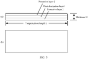
- FIG. 3 (a) in FIG. 3 is a front view of the film-like heat dissipation member shown in FIG. 2
- FIG. 3 is a top view of the film-like heat dissipation member shown in FIG. 5
- the top view is a rectangle in this example, but is not limited to the rectangle in another embodiment.
- tangent-plane lengths of the film-like heat dissipation member in an unfolded state are all L
- a thickness of the film-like heat dissipation member is H in (a) in FIG. 3 .
- FIG. 4 is a schematic diagram of the film-like heat dissipation member shown in FIG. 2 in a bent state.
- an arc between A1 and A2 and an arc between B1 and B2 are on different tangent planes of the film-like heat dissipation member, and the tangent planes are vertical to a thickness direction.
- Lengths of the arc between A1 and A2 and the arc between B 1 and B2 are tangent-plane lengths of the different tangent planes of the film-like heat dissipation member, and the tangent-plane lengths are L1 and L2. Because the film-like heat dissipation material is compressed or stretched based on elasticity of the film-like heat dissipation material in the bending process, different tangent-plane lengths of the film-like heat dissipation material change. It may be known that L1 > L > L2.
- An embodiment of the present invention provides a film-like heat dissipation member, including a heat dissipation layer.
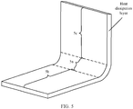
- FIG. 5 shows the heat dissipation layer in a bent state.
- a surface of the heat dissipation layer includes a non-planar region 5a and planar regions 5b and 5c, and the heat dissipation layer may be made of one or more layers of heat-conducting materials.
- a connection between a non-planar region and a planar region is a continuous connection.
- the heat dissipation layer is a complete heat-conducting material.
- the heat-conducting material in the non-planar region 5a may be corrugated.
- FIG. 6 is a schematic diagram of a corrugation.
- Each hinge zone (for example, 601 in FIG. 6 ) in the corrugation connects two limbs (for example, 603 and 604 in FIG. 6 ).
- the hinge zones (601 and 602) may be in any one or more of the following shapes: an arc ((a) in FIG. 7 and (b) in FIG. 7 ), a chevron ((c) in FIG. 7 ), or a box ((d) in FIG. 7 ).
- the non-planar region 5a includes at least one hinge zone.
- the following describes a structure of the film-like heat dissipation member in detail by using an example in which the hinge zone of the corrugation shape is arc-shaped.
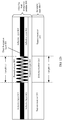
- FIG. 8 is a front view of a film-like heat dissipation member 800 in an unfolded state according to an embodiment of the present invention.
- the film-like heat dissipation member includes a heat dissipation layer 801, and further includes adhesive layers (802 and 803) on surfaces of the heat dissipation layer, and protective layers (804 and 805) adhered to the heat dissipation layer by using the adhesive layers. Adhesive layers may not be disposed between a non-planar region and the protective layers of the heat dissipation layer 801.
- a heat-conducting material in the non-planar region of the heat dissipation layer 801 is corrugated (which may also be understood as rippled), and a hinge zone of the corrugation shape is arc-shaped.
- a tangent-plane length of the film-like heat dissipation member 800 in the unfolded state is L, and a thickness of a planar region of the film-like heat dissipation member is H.
- FIG.9 is a schematic diagram of a corrugation with an arc-shaped hinge zone.
- a height h between adjacent hinge zones in the corrugation may be set as required, and may be greater than H, or may be less than or equal to H.
- An angle ⁇ formed by two limbs connected by the hinge zone may be 1° to 179°.
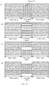
- FIG. 10 is a top view of the heat dissipation layer in FIG. 8 in an unfolded state. Dashed lines represent the hinge zone of the corrugation in the non-planar region in FIG. 8 .
- the corrugation in the non-planar region may be a continuous corrugation in a direction parallel to that of a connection between a non-planar region and a planar region, as shown in (a) in FIG. 10 , or may be a non-continuous corrugation, as shown in (b), (c), and (d) in FIG. 10.
- FIG. 10 merely presents some possible schematic diagrams and does not impose any limitation.
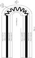
- FIG. 11 is a front view of the film-like heat dissipation member 800 in a bent state according to an embodiment of the present invention.
- tangent-plane lengths of the film-like heat dissipation member change.
- the film-like heat dissipation member in the non-planar region is compressed on an inner bending side, and the film-like heat dissipation member in the non-planar region is stretched on an outer bending side.
- a protective layer and an adhesive layer that have elasticity can be adapted to a tangent-plane length change in the film-like heat dissipation member in the bending process based on length changes in the protective layer and the adhesive layer.
- a tangent-plane length can change by compressing and stretching a corrugation in the non-planar region, without compressing or stretching the heat-conducting material.
- the heat-conducting material of the heat dissipation layer of the film-like heat dissipation member provided in this embodiment of the present invention may be bent repeatedly.
- An embodiment of the present invention provides a film-like heat dissipation member, applied to a bendable apparatus.
- the following describes, by using the film-like heat dissipation member 800 as an example, a specific structure in which the film-like heat dissipation member 800 provided in this embodiment of the present invention is applied to the bendable apparatus 2.
- FIG. 12a to FIG. 12c are front views showing that the film-like heat dissipation member 800 is applied to the bendable apparatus.
- the film-like heat dissipation member includes the heat dissipation layer 801.
- the bendable apparatus 2 includes the two support members 201 and 202 and the bending member 203 located between the two support members.
- a surface of the film-like heat dissipation member is directly or indirectly attached to a surface of the bendable apparatus by using a protective layer. Tangent-plane lengths of the film-like heat dissipation member change as the bendable apparatus is bent.
- the heat dissipation layer 801 is made of a heat-conducting material, the surface of the heat dissipation layer includes a non-planar region and a planar region, and the heat dissipation layer spans the two support members, so that the non-planar region covers a part of a surface or an entire surface of the bending member 203. As shown in FIG. 12a and FIG. 12b , the non-planar region covers the entire surface of the bending member 203. As shown in FIG.
- the non-planar region covers the part of the surface of the bending member 203.
- a length of the non-planar region of the heat dissipation layer is L3
- a length of the bending member 203 is L4.
- L3 may be greater than or equal to L4, or may be less than L4.
- the heat-conducting material in the non-planar region is corrugated, so that tangent-plane lengths of the film-like heat dissipation member change in a bending process based on the corrugated heat-conducting material.
- heat on one support member on one side may be transferred across the bending member to the other support member on the other side by using the corrugated heat-conducting material for the non-planar region of the heat dissipation layer in the film-like heat dissipation member.
- An embodiment of the present invention provides a film-like heat dissipation member.
- the film-like heat dissipation member includes a heat dissipation layer, a surface of the heat dissipation layer is formed by splicing an elastic material and a heat-conducting material, and the elastic material is spliced at any one or more ends of the heat-conducting material, so that the heat dissipation layer may be stretched and compressed in a process of bending the surface.
- FIG. 13 is a schematic diagram of the heat dissipation layer in an unfolded state. In (a) in FIG. 13 , the elastic material is spliced at two ends of the heat-conducting material; in (b) in FIG. 13 , the elastic material is spliced at one end of the heat-conducting material; and in (c) in FIG. 13 , the elastic material is spliced around the heat-conducting material.
- splicing surfaces are adhered, or the elastic material is inserted into the heat-conducting material, or the heat-conducting material is inserted into the elastic material.
- the splicing surfaces may be planes as shown in FIG. 13 , or may be sawtooth-shaped.
- FIG. 14a and FIG. 14b Using that the heat-conducting material is inserted into the elastic material as an example, splicing manners may be shown in FIG. 14a and FIG. 14b .
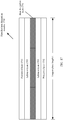
- a film-like heat dissipation member 1500 may further include a protective layer 1502 located on a surface of a heat dissipation layer 1501.
- the protective layer and the heat dissipation layer may be adhered to each other by using an adhesive layer 1503, and the protective layer may be made of one or more layers of elastic materials.
- the protective layer and the adhesive layer that have elasticity can be adapted to tangent-plane length changes in different tangent planes in the bending process based on length changes in the protective layer and the adhesive layer.
- splicing the elastic material allows the heat dissipation layer to be adapted to the tangent-plane length changes in the different tangent planes based on high elasticity of the elastic material in the bending process.
- FIG. 16 is a front view showing that the film-like heat dissipation member 1500 is applied to the bendable apparatus 2.
- the bendable apparatus 2 includes the two support members 201 and 202 and the bending member 203 located between the two support members.
- a surface of the film-like heat dissipation member 1500 is directly or indirectly attached to a surface of the bendable apparatus 2 by using a protective layer.
- a tangent-plane length of the film-like heat dissipation member 1500 changes as the bendable apparatus 2 is bent.
- a heat-conducting material spans the two support members, so that the heat-conducting material covers an entire surface of the bending member.
- heat on one support member on one side may be transferred across the bending member to the other support member on the other side by using the heat-conducting material of the film-like heat dissipation member.
- An embodiment of the present invention provides a film-like heat dissipation member 1700, including a heat dissipation layer 1701.
- FIG. 17 is a front view of the film-like heat dissipation member 1700.
- the film-like heat dissipation member 1700 further includes a protective layer 1502 on a surface of a heat dissipation layer 1501.
- the protective layer and the heat dissipation layer may be adhered to each other by using an adhesive layer 1503, and the protective layer may be made of one or more layers of elastic materials.
- the surface of the heat dissipation layer 1701 is formed by splicing at least two heat-conducting materials by using sawteeth.
- the sawteeth are in any one of a rectangle, a triangle, a trapezoid, and a U-shape, and corresponding top views are shown in (a), (b), (c), and (d) in FIG. 18 , respectively.
- the heat dissipation layer in FIG. 18 is formed by splicing three heat-conducting materials by using sawteeth.
- the protective layer and the adhesive layer that have elasticity can be adapted to tangent-plane length changes in different tangent planes in the bending process based on length changes in the protective layer and the adhesive layer.
- the tangent-plane lengths of the different tangent planes of the heat dissipation layer change through misalignment of sawteeth during splicing.
- FIG. 19 is a schematic diagram of misalignment of rectangular sawteeth.
- FIG. 20 is a front view showing that the film-like heat dissipation member 1700 is applied to the bendable apparatus 2.
- the bendable apparatus 2 includes the two support members 201 and 202 and the bending member 203 located between the two support members.
- a surface of the film-like heat dissipation member 1700 is directly or indirectly attached to a surface of the bendable apparatus 2 by using a protective layer.
- a tangent-plane length of the film-like heat dissipation member 1700 changes as the bendable apparatus 2 is bent.
- heat on one support member on one side may be transferred across the bending member to the other support member on the other side by using the heat-conducting material of the film-like heat dissipation member.
Landscapes
- Engineering & Computer Science (AREA)
- Physics & Mathematics (AREA)
- Theoretical Computer Science (AREA)
- Thermal Sciences (AREA)
- Microelectronics & Electronic Packaging (AREA)
- General Physics & Mathematics (AREA)
- Computer Hardware Design (AREA)
- General Engineering & Computer Science (AREA)
- Human Computer Interaction (AREA)
- Mechanical Engineering (AREA)
- Signal Processing (AREA)
- Mathematical Physics (AREA)
- Cooling Or The Like Of Electrical Apparatus (AREA)
- Devices For Indicating Variable Information By Combining Individual Elements (AREA)
- Electroluminescent Light Sources (AREA)
- Cooling Or The Like Of Semiconductors Or Solid State Devices (AREA)
- Laminated Bodies (AREA)
- Shaping Of Tube Ends By Bending Or Straightening (AREA)
Applications Claiming Priority (2)
| Application Number | Priority Date | Filing Date | Title |
|---|---|---|---|
| CN201710983771.0A CN109699151B (zh) | 2017-10-20 | 2017-10-20 | 膜状散热构件、可折弯显示装置以及终端设备 |
| PCT/CN2018/093582 WO2019076081A1 (fr) | 2017-10-20 | 2018-06-29 | Élément de dissipation de chaleur en forme de film, dispositif d'affichage pliable, et appareil d'équipement terminal |
Publications (2)
| Publication Number | Publication Date |
|---|---|
| EP3697184A1 true EP3697184A1 (fr) | 2020-08-19 |
| EP3697184A4 EP3697184A4 (fr) | 2020-12-09 |
Family
ID=66173179
Family Applications (1)
| Application Number | Title | Priority Date | Filing Date |
|---|---|---|---|
| EP18869197.6A Pending EP3697184A4 (fr) | 2017-10-20 | 2018-06-29 | Élément de dissipation de chaleur en forme de film, dispositif d'affichage pliable, et appareil d'équipement terminal |
Country Status (6)
| Country | Link |
|---|---|
| US (2) | US11406044B2 (fr) |
| EP (1) | EP3697184A4 (fr) |
| JP (1) | JP7143408B2 (fr) |
| KR (1) | KR102427542B1 (fr) |
| CN (1) | CN109699151B (fr) |
| WO (1) | WO2019076081A1 (fr) |
Cited By (3)
| Publication number | Priority date | Publication date | Assignee | Title |
|---|---|---|---|---|
| CN113270030A (zh) * | 2020-02-14 | 2021-08-17 | 三星显示有限公司 | 显示设备 |
| EP4113958A4 (fr) * | 2020-03-30 | 2023-08-16 | Huawei Technologies Co., Ltd. | Terminal mobile |
| EP4367987A4 (fr) * | 2021-07-09 | 2025-05-07 | NeoGraf Solutions, LLC | Structure de graphite flexible |
Families Citing this family (63)
| Publication number | Priority date | Publication date | Assignee | Title |
|---|---|---|---|---|
| JP6890180B2 (ja) * | 2016-11-25 | 2021-06-18 | 華為技術有限公司Huawei Technologies Co.,Ltd. | 熱放散パネル、熱放散装置、及び電子デバイス |
| CN109699151B (zh) | 2017-10-20 | 2020-02-14 | 华为技术有限公司 | 膜状散热构件、可折弯显示装置以及终端设备 |
| KR102676661B1 (ko) * | 2019-05-22 | 2024-06-24 | 삼성디스플레이 주식회사 | 표시모듈 제조방법 |
| CN110497659B (zh) * | 2019-07-18 | 2024-07-09 | 铭尔金属(苏州)有限公司 | 一种复合材料及其制备方法及使用其的电子产品 |
| CN110556059A (zh) * | 2019-09-03 | 2019-12-10 | 武汉华星光电半导体显示技术有限公司 | 柔性显示装置及提升其稳定性的方法 |
| KR102751451B1 (ko) * | 2019-10-22 | 2025-01-10 | 삼성전자주식회사 | 디스플레이 보호 구조를 포함하는 폴더블 전자 장치 |
| CN112750365A (zh) * | 2019-10-31 | 2021-05-04 | 华为技术有限公司 | 一种柔性显示屏及电子设备 |
| CN110796955B (zh) * | 2019-11-13 | 2021-12-03 | 京东方科技集团股份有限公司 | 柔性显示屏和电子设备 |
| CN111147630B (zh) * | 2019-12-20 | 2021-04-09 | 华为技术有限公司 | 折叠屏设备 |
| CN113133268A (zh) * | 2019-12-31 | 2021-07-16 | 深圳市柔宇科技有限公司 | 散热件及其制作方法以及可弯折装置 |
| CN111564677A (zh) * | 2020-05-25 | 2020-08-21 | 京东方科技集团股份有限公司 | 柔性显示装置 |
| CN113811136B (zh) * | 2020-06-13 | 2023-06-02 | 华为技术有限公司 | 可折弯显示装置及其散热装置 |
| KR102932215B1 (ko) | 2020-06-29 | 2026-03-03 | 엘지이노텍 주식회사 | 탄성 부재 및 이를 포함하는 디스플레이 장치 |
| CN114080137B (zh) * | 2020-08-14 | 2026-01-06 | 中兴通讯股份有限公司 | 散热结构、散热部件及其安装方法、可折叠终端 |
| KR20220032831A (ko) | 2020-09-08 | 2022-03-15 | 엘지디스플레이 주식회사 | 표시 장치 |
| KR102715359B1 (ko) * | 2020-11-13 | 2024-10-11 | 주식회사 아모그린텍 | 폴딩 플레이트 및 이의 제조방법 |
| WO2022102986A1 (fr) * | 2020-11-16 | 2022-05-19 | 삼성전자 주식회사 | Dispositif électronique comprenant un élément de diffusion thermique |
| KR102744191B1 (ko) * | 2020-11-17 | 2024-12-18 | 주식회사 아모그린텍 | 폴딩 플레이트 및 이의 제조방법 |
| KR20220093569A (ko) * | 2020-12-28 | 2022-07-05 | 엘지디스플레이 주식회사 | 폴더블 표시 장치 |
| CN112767838B (zh) * | 2021-01-19 | 2022-10-21 | Oppo(重庆)智能科技有限公司 | 柔性显示屏和电子设备 |
| KR102582486B1 (ko) | 2021-01-20 | 2023-09-25 | 삼성전자주식회사 | 폴더블 디스플레이를 포함하는 전자 장치 |
| KR102902072B1 (ko) * | 2021-02-01 | 2025-12-19 | 삼성전자주식회사 | 전자 장치 |
| US11416040B1 (en) * | 2021-03-12 | 2022-08-16 | Motorola Mobility Llc | Hinged electronic device with flexible display and heat spreader |
| CN115135093A (zh) * | 2021-03-26 | 2022-09-30 | 北京小米移动软件有限公司 | 电子设备 |
| CN113066380A (zh) * | 2021-03-29 | 2021-07-02 | 武汉华星光电半导体显示技术有限公司 | 显示面板及显示装置 |
| KR102932330B1 (ko) | 2021-03-30 | 2026-03-03 | 삼성디스플레이 주식회사 | 표시 장치 |
| KR20220158162A (ko) * | 2021-05-21 | 2022-11-30 | 삼성디스플레이 주식회사 | 표시 장치 |
| US11907031B2 (en) * | 2021-05-21 | 2024-02-20 | Samsung Display Co., Ltd. | Display device and electronic device including the same |
| CN113284420B (zh) * | 2021-05-26 | 2022-12-06 | 武汉华星光电半导体显示技术有限公司 | 显示装置 |
| CN115413184A (zh) * | 2021-05-29 | 2022-11-29 | 华为技术有限公司 | 一种散热系统和电子设备 |
| CN113292971A (zh) * | 2021-06-01 | 2021-08-24 | 江西德思恩新材料有限公司 | 一种用于散热功能的增强抗拉强度人工石墨膜及其制备方法 |
| CN113299195B (zh) * | 2021-06-02 | 2022-10-04 | 武汉华星光电半导体显示技术有限公司 | 折叠显示装置 |
| CN113380150B (zh) * | 2021-06-24 | 2022-11-15 | 云谷(固安)科技有限公司 | 复合层和显示面板 |
| CN113450668B (zh) * | 2021-06-30 | 2022-09-13 | 上海天马微电子有限公司 | 散热组件、显示装置及显示装置的组装方法 |
| US12287684B2 (en) | 2021-07-09 | 2025-04-29 | Samsung Electronics Co., Ltd. | Electronic device including heat transfer member |
| KR102906432B1 (ko) * | 2021-07-09 | 2026-01-02 | 삼성전자주식회사 | 열전달 부재를 포함하는 전자 장치 |
| CN113539112B (zh) * | 2021-07-30 | 2022-10-18 | 上海天马微电子有限公司 | 显示装置 |
| KR20230022374A (ko) * | 2021-08-06 | 2023-02-15 | 삼성디스플레이 주식회사 | 표시 장치 |
| KR20230035166A (ko) | 2021-09-03 | 2023-03-13 | 삼성디스플레이 주식회사 | 표시 장치 |
| JP2024539535A (ja) * | 2021-09-03 | 2024-10-29 | 三星ディスプレイ株式會社 | 表示装置 |
| CN113870714B (zh) * | 2021-09-29 | 2023-10-31 | 武汉华星光电半导体显示技术有限公司 | 一种折叠显示背板及显示终端 |
| CN113823190B (zh) * | 2021-09-30 | 2023-11-28 | 武汉华星光电半导体显示技术有限公司 | 支撑复合板及显示模组 |
| KR20230049818A (ko) * | 2021-10-06 | 2023-04-14 | 삼성디스플레이 주식회사 | 표시 장치 |
| US12328845B2 (en) * | 2021-12-20 | 2025-06-10 | Meta Platforms Technologies, Llc | Thermal conduit for electronic device |
| CN114513932A (zh) * | 2022-01-10 | 2022-05-17 | 江西德思恩新材料有限公司 | 一种方便可折叠手机安装使用的可折叠石墨膜的生产方法 |
| US12079046B2 (en) * | 2022-01-31 | 2024-09-03 | Dell Products L.P. | Bonded hinge structure for an information handling system |
| US12349316B2 (en) * | 2022-02-03 | 2025-07-01 | Intel Corporation | Thermal conduction band for improved mobile computing device performance |
| KR102708954B1 (ko) * | 2022-04-18 | 2024-09-25 | 주식회사 제이월드 | 폴더블 디스플레이 장치의 힌지부 메인프레임용 방열시트 |
| KR102708962B1 (ko) * | 2022-04-18 | 2024-09-25 | 주식회사 제이월드 | 폴더블 디스플레이 장치의 힌지부 메인프레임용 방열시트 |
| KR102708976B1 (ko) * | 2022-05-06 | 2024-09-25 | 주식회사 제이월드 | 확장형 슬라이딩 구조의 방열시트 |
| KR102751793B1 (ko) * | 2022-05-23 | 2025-01-09 | 주식회사 아모그린텍 | 방열시트 및 이를 포함하는 전자기기 |
| WO2024035235A1 (fr) * | 2022-08-11 | 2024-02-15 | 삼성전자 주식회사 | Dispositif électronique comprenant un élément de dissipation de chaleur |
| CN115167646B (zh) * | 2022-09-02 | 2022-12-09 | 常州威图流体科技有限公司 | 可弯折液冷散热模组及折叠屏电子终端 |
| CN119836851A (zh) * | 2022-09-08 | 2025-04-15 | 三星电子株式会社 | 包括用于消散电子装置中产生的热量的结构的电子装置 |
| KR20240036757A (ko) * | 2022-09-13 | 2024-03-21 | 삼성디스플레이 주식회사 | 표시 장치 |
| WO2024058464A1 (fr) * | 2022-09-16 | 2024-03-21 | 삼성전자주식회사 | Dispositif électronique comprenant une couche flexible |
| EP4475517A4 (fr) * | 2022-09-30 | 2025-09-24 | Samsung Electronics Co Ltd | Dispositif électronique comprenant un raidisseur |
| KR102762711B1 (ko) * | 2022-12-13 | 2025-02-05 | 주식회사 제이월드 | 확장형 방열시트 |
| KR20240102590A (ko) * | 2022-12-26 | 2024-07-03 | 엘지디스플레이 주식회사 | 표시 장치 |
| KR102730290B1 (ko) * | 2022-12-27 | 2024-11-13 | 한국세라믹기술원 | 허니컴 구조를 갖는 폴더블 단말용 방열 필름 |
| CN117119087B (zh) * | 2023-04-21 | 2024-09-24 | 荣耀终端有限公司 | 转动机构及终端设备 |
| JP2024179991A (ja) * | 2023-06-16 | 2024-12-26 | レノボ・シンガポール・プライベート・リミテッド | 電子機器 |
| KR20250026940A (ko) * | 2023-08-18 | 2025-02-25 | 엘지디스플레이 주식회사 | 표시 장치 |
Family Cites Families (46)
| Publication number | Priority date | Publication date | Assignee | Title |
|---|---|---|---|---|
| JP3885246B2 (ja) | 1996-01-12 | 2007-02-21 | 松下電器産業株式会社 | プラズマディスプレイパネル |
| JPH10262719A (ja) * | 1997-03-27 | 1998-10-06 | Mitsubishi Electric Corp | ノートパソコン収納ケース |
| US6075696A (en) * | 1997-11-06 | 2000-06-13 | Compaq Computer Corporation | Portable computer with flexible heat spreader plate structure therein |
| JP2000010661A (ja) * | 1998-06-18 | 2000-01-14 | Mitsubishi Electric Corp | 携帯型情報処理装置および携帯型情報処理装置用カバー、卓上型情報処理装置 |
| US6052280A (en) * | 1999-01-19 | 2000-04-18 | Alliedsignal Inc. | Carbon/carbon heat spreader |
| KR100760509B1 (ko) * | 2004-12-14 | 2007-09-20 | 삼성전자주식회사 | 폴더 타입 휴대용 무선단말기의 방열 장치 |
| CN2762508Y (zh) * | 2004-12-22 | 2006-03-01 | 珍通科技股份有限公司 | 弯折式均温板 |
| CN200965430Y (zh) * | 2006-10-25 | 2007-10-24 | 泰硕电子股份有限公司 | 可挠曲的散热管 |
| JP2008160029A (ja) * | 2006-12-26 | 2008-07-10 | Toshiba Corp | 冷却構造および電子機器 |
| JP4847879B2 (ja) * | 2007-01-17 | 2011-12-28 | ソニー エリクソン モバイル コミュニケーションズ, エービー | 放熱構造体及び携帯端末 |
| CN201044555Y (zh) * | 2007-04-30 | 2008-04-02 | 深圳市中兴新通讯设备有限公司 | 通讯设备用热交换器换热芯体 |
| JP2008305284A (ja) * | 2007-06-11 | 2008-12-18 | Lenovo Singapore Pte Ltd | 携帯式コンピュータ |
| JP4888413B2 (ja) * | 2008-02-14 | 2012-02-29 | 富士通株式会社 | 携帯型電子装置 |
| JP5381447B2 (ja) * | 2009-07-21 | 2014-01-08 | セイコーエプソン株式会社 | 電気光学装置 |
| CN102032832B (zh) * | 2010-10-22 | 2012-11-07 | 浙江大学 | 一种柔性换热件及其加工方法 |
| JP2012182398A (ja) * | 2011-03-03 | 2012-09-20 | Hitachi Ltd | 冷却構造 |
| CN202143337U (zh) * | 2011-07-11 | 2012-02-08 | 讯凯国际股份有限公司 | 用于增加段差转折处的结构强度的散热板结构 |
| CN102271486A (zh) * | 2011-07-21 | 2011-12-07 | 尹钟哲 | 一种散热结构及其应用、制备装置和制备方法 |
| US10013020B2 (en) * | 2014-01-29 | 2018-07-03 | Hewlett-Packard Development Company, L.P. | Electronic device with flexible display |
| KR102210047B1 (ko) * | 2014-03-05 | 2021-02-01 | 엘지디스플레이 주식회사 | 접이식 디스플레이 장치 |
| US9939672B2 (en) * | 2014-06-13 | 2018-04-10 | Apple Inc. | Electronic device with heat spreading film |
| WO2016015032A1 (fr) * | 2014-07-25 | 2016-01-28 | Graftech International Holdings Inc. | Carte de circuit imprimé flexible ayant un substrat de graphite et agencements de circuits utilisant cette dernière |
| WO2016048335A1 (fr) * | 2014-09-26 | 2016-03-31 | W.L. Gore & Associates Gmbh | Procédé de production d'un article thermoconducteur |
| CN204144262U (zh) * | 2014-10-29 | 2015-02-04 | 昆山工研院新型平板显示技术中心有限公司 | 一种散热性良好的柔性显示器 |
| US9490860B2 (en) * | 2014-12-17 | 2016-11-08 | Asia Vital Components Co., Ltd. | Protective device capable of dissipating heat |
| KR102276380B1 (ko) * | 2015-01-15 | 2021-07-13 | 삼성디스플레이 주식회사 | 접이식 표시 장치 |
| CN204884440U (zh) * | 2015-08-27 | 2015-12-16 | 京东方科技集团股份有限公司 | 柔性显示面板和柔性显示装置 |
| KR20170040435A (ko) * | 2015-10-02 | 2017-04-13 | 삼성디스플레이 주식회사 | 표시 장치 |
| CN205883828U (zh) * | 2016-07-14 | 2017-01-11 | 深圳Tcl新技术有限公司 | 显示装置及其散热组件 |
| CN106378984B (zh) | 2016-08-29 | 2019-05-03 | 上海复合材料科技有限公司 | 轻质柔性高导热纳米碳复合膜及其制备方法 |
| KR101743022B1 (ko) * | 2016-10-31 | 2017-06-02 | 신화인터텍 주식회사 | 방열 시트 및 그 제조 방법 |
| CN106499878A (zh) | 2016-11-04 | 2017-03-15 | 天津兴科启智科技发展有限公司 | 一种可伸缩热管 |
| JP6890180B2 (ja) * | 2016-11-25 | 2021-06-18 | 華為技術有限公司Huawei Technologies Co.,Ltd. | 熱放散パネル、熱放散装置、及び電子デバイス |
| CN108573656A (zh) * | 2017-03-14 | 2018-09-25 | 昆山工研院新型平板显示技术中心有限公司 | 一种柔性显示屏以及柔性显示装置 |
| US10488898B2 (en) * | 2017-03-31 | 2019-11-26 | Microsoft Technology Licensing, Llc | Flexible heat spreader |
| CN106973549B (zh) * | 2017-04-10 | 2019-09-10 | 上海天马微电子有限公司 | 一种柔性显示装置 |
| US10120421B1 (en) * | 2017-06-21 | 2018-11-06 | Dell Products L.P. | Flexible information handling system display |
| JP6642542B2 (ja) * | 2017-08-30 | 2020-02-05 | トヨタ自動車株式会社 | 放熱シート |
| CN109699151B (zh) | 2017-10-20 | 2020-02-14 | 华为技术有限公司 | 膜状散热构件、可折弯显示装置以及终端设备 |
| CN108766246A (zh) * | 2018-07-18 | 2018-11-06 | 昆山国显光电有限公司 | 显示面板及显示装置 |
| US11231757B2 (en) * | 2018-08-01 | 2022-01-25 | Intel Corporation | Thermal dissipation in dual-chassis devices |
| KR102632543B1 (ko) * | 2019-02-19 | 2024-02-01 | 삼성디스플레이 주식회사 | 결합 부재를 포함하는 표시 장치 |
| CN115485755B (zh) * | 2019-03-05 | 2025-03-21 | 京东方科技集团股份有限公司 | 一种柔性屏 |
| CN110796955B (zh) * | 2019-11-13 | 2021-12-03 | 京东方科技集团股份有限公司 | 柔性显示屏和电子设备 |
| KR102711319B1 (ko) * | 2020-08-24 | 2024-09-26 | 엘지디스플레이 주식회사 | 디스플레이 모듈 및 디스플레이 장치 |
| KR20230101074A (ko) * | 2021-12-29 | 2023-07-06 | 엘지디스플레이 주식회사 | 디스플레이 장치 |
-
2017
- 2017-10-20 CN CN201710983771.0A patent/CN109699151B/zh active Active
-
2018
- 2018-06-29 KR KR1020207014002A patent/KR102427542B1/ko active Active
- 2018-06-29 WO PCT/CN2018/093582 patent/WO2019076081A1/fr not_active Ceased
- 2018-06-29 EP EP18869197.6A patent/EP3697184A4/fr active Pending
- 2018-06-29 JP JP2020521984A patent/JP7143408B2/ja active Active
-
2020
- 2020-04-17 US US16/851,337 patent/US11406044B2/en active Active
-
2022
- 2022-07-07 US US17/859,034 patent/US11963336B2/en active Active
Cited By (8)
| Publication number | Priority date | Publication date | Assignee | Title |
|---|---|---|---|---|
| CN113270030A (zh) * | 2020-02-14 | 2021-08-17 | 三星显示有限公司 | 显示设备 |
| EP3865972A1 (fr) * | 2020-02-14 | 2021-08-18 | Samsung Display Co., Ltd. | Dispositif d'affichage |
| US11216029B2 (en) | 2020-02-14 | 2022-01-04 | Samsung Display Co., Ltd | Display device |
| US11797047B2 (en) | 2020-02-14 | 2023-10-24 | Samsung Display Co., Ltd. | Display device |
| US12326756B2 (en) | 2020-02-14 | 2025-06-10 | Samsung Display Co., Ltd. | Display device |
| CN113270030B (zh) * | 2020-02-14 | 2026-01-30 | 三星显示有限公司 | 显示设备 |
| EP4113958A4 (fr) * | 2020-03-30 | 2023-08-16 | Huawei Technologies Co., Ltd. | Terminal mobile |
| EP4367987A4 (fr) * | 2021-07-09 | 2025-05-07 | NeoGraf Solutions, LLC | Structure de graphite flexible |
Also Published As
| Publication number | Publication date |
|---|---|
| EP3697184A4 (fr) | 2020-12-09 |
| US11963336B2 (en) | 2024-04-16 |
| KR20200070336A (ko) | 2020-06-17 |
| US20220338381A1 (en) | 2022-10-20 |
| JP2021501464A (ja) | 2021-01-14 |
| WO2019076081A1 (fr) | 2019-04-25 |
| CN109699151B (zh) | 2020-02-14 |
| JP7143408B2 (ja) | 2022-09-28 |
| US20200245501A1 (en) | 2020-07-30 |
| KR102427542B1 (ko) | 2022-07-29 |
| US11406044B2 (en) | 2022-08-02 |
| CN109699151A (zh) | 2019-04-30 |
Similar Documents
| Publication | Publication Date | Title |
|---|---|---|
| US11963336B2 (en) | Film-like heat dissipation member, bendable display apparatus, and terminal device | |
| US11011713B2 (en) | Display module and electronic apparatus | |
| US20240157669A1 (en) | Display module and display apparatus | |
| CN114730534B (zh) | 显示器用基板 | |
| US11178779B2 (en) | Display device | |
| CN209447443U (zh) | 显示面板及显示装置 | |
| KR101933818B1 (ko) | 가요성 디스플레이 장치 및 전자 장치 | |
| US9989790B2 (en) | Display device | |
| EP3671703B1 (fr) | Plaque de couverture pliable, module d'affichage pliable et dispositif terminal pliable | |
| CN110491882A (zh) | 柔性电路板、显示面板及显示装置 | |
| US12484417B2 (en) | Flexible display panel and flexible display device | |
| CN113888964B (zh) | 显示设备 | |
| US11770893B2 (en) | Display device | |
| US11116107B2 (en) | Flexible screen | |
| CN115410480B (zh) | 显示装置和电子设备 | |
| CN109637382A (zh) | 显示面板及显示装置 | |
| CN112002227A (zh) | 柔性显示面板及柔性显示设备 | |
| JP2016061977A (ja) | 表示装置及び携帯端末装置 | |
| CN112767838B (zh) | 柔性显示屏和电子设备 | |
| US20250085746A1 (en) | Display panel | |
| KR102708954B1 (ko) | 폴더블 디스플레이 장치의 힌지부 메인프레임용 방열시트 | |
| CN107193333A (zh) | 显示装置及其显示模块 | |
| CN120513471A (zh) | 弹性构件和包括该弹性构件的显示装置 | |
| US20150016041A1 (en) | Electronic apparatus and module | |
| CN104703388A (zh) | 软性电路板及应用其的曲型显示装置 |
Legal Events
| Date | Code | Title | Description |
|---|---|---|---|
| STAA | Information on the status of an ep patent application or granted ep patent |
Free format text: STATUS: THE INTERNATIONAL PUBLICATION HAS BEEN MADE |
|
| PUAI | Public reference made under article 153(3) epc to a published international application that has entered the european phase |
Free format text: ORIGINAL CODE: 0009012 |
|
| STAA | Information on the status of an ep patent application or granted ep patent |
Free format text: STATUS: REQUEST FOR EXAMINATION WAS MADE |
|
| 17P | Request for examination filed |
Effective date: 20200515 |
|
| AK | Designated contracting states |
Kind code of ref document: A1 Designated state(s): AL AT BE BG CH CY CZ DE DK EE ES FI FR GB GR HR HU IE IS IT LI LT LU LV MC MK MT NL NO PL PT RO RS SE SI SK SM TR |
|
| AX | Request for extension of the european patent |
Extension state: BA ME |
|
| REG | Reference to a national code |
Ref country code: DE Ref legal event code: R079 Free format text: PREVIOUS MAIN CLASS: H05K0007200000 Ipc: F28F0003020000 |
|
| A4 | Supplementary search report drawn up and despatched |
Effective date: 20201109 |
|
| RIC1 | Information provided on ipc code assigned before grant |
Ipc: G09F 9/30 20060101ALI20201103BHEP Ipc: G06F 1/16 20060101ALI20201103BHEP Ipc: F28F 3/02 20060101AFI20201103BHEP Ipc: G06F 1/20 20060101ALI20201103BHEP Ipc: H05K 7/20 20060101ALI20201103BHEP |
|
| DAV | Request for validation of the european patent (deleted) | ||
| DAX | Request for extension of the european patent (deleted) | ||
| STAA | Information on the status of an ep patent application or granted ep patent |
Free format text: STATUS: EXAMINATION IS IN PROGRESS |
|
| 17Q | First examination report despatched |
Effective date: 20231120 |
|
| GRAP | Despatch of communication of intention to grant a patent |
Free format text: ORIGINAL CODE: EPIDOSNIGR1 |
|
| STAA | Information on the status of an ep patent application or granted ep patent |
Free format text: STATUS: GRANT OF PATENT IS INTENDED |