EP3697193B1 - Siebbandeinheit für eine erntemaschine sowie zugehörige klappeneinheit - Google Patents
Siebbandeinheit für eine erntemaschine sowie zugehörige klappeneinheit Download PDFInfo
- Publication number
- EP3697193B1 EP3697193B1 EP18799675.6A EP18799675A EP3697193B1 EP 3697193 B1 EP3697193 B1 EP 3697193B1 EP 18799675 A EP18799675 A EP 18799675A EP 3697193 B1 EP3697193 B1 EP 3697193B1
- Authority
- EP
- European Patent Office
- Prior art keywords
- sieve
- positioning means
- belt unit
- bar
- bars
- Prior art date
- Legal status (The legal status is an assumption and is not a legal conclusion. Google has not performed a legal analysis and makes no representation as to the accuracy of the status listed.)
- Active
Links
Images





Classifications
-
- A—HUMAN NECESSITIES
- A01—AGRICULTURE; FORESTRY; ANIMAL HUSBANDRY; HUNTING; TRAPPING; FISHING
- A01D—HARVESTING; MOWING
- A01D17/00—Digging machines with sieving and conveying mechanisms
- A01D17/10—Digging machines with sieving and conveying mechanisms with smooth conveyor belts, lath bands or rake bands
-
- A—HUMAN NECESSITIES
- A01—AGRICULTURE; FORESTRY; ANIMAL HUSBANDRY; HUNTING; TRAPPING; FISHING
- A01D—HARVESTING; MOWING
- A01D33/00—Accessories for digging harvesters
-
- B—PERFORMING OPERATIONS; TRANSPORTING
- B07—SEPARATING SOLIDS FROM SOLIDS; SORTING
- B07B—SEPARATING SOLIDS FROM SOLIDS BY SIEVING, SCREENING, SIFTING OR BY USING GAS CURRENTS; SEPARATING BY OTHER DRY METHODS APPLICABLE TO BULK MATERIAL, e.g. LOOSE ARTICLES FIT TO BE HANDLED LIKE BULK MATERIAL
- B07B1/00—Sieving, screening, sifting, or sorting solid materials using networks, gratings, grids, or the like
- B07B1/10—Screens in the form of endless moving bands
-
- B—PERFORMING OPERATIONS; TRANSPORTING
- B65—CONVEYING; PACKING; STORING; HANDLING THIN OR FILAMENTARY MATERIAL
- B65G—TRANSPORT OR STORAGE DEVICES, e.g. CONVEYORS FOR LOADING OR TIPPING, SHOP CONVEYOR SYSTEMS OR PNEUMATIC TUBE CONVEYORS
- B65G15/00—Conveyors having endless load-conveying surfaces, i.e. belts and like continuous members, to which tractive effort is transmitted by means other than endless driving elements of similar configuration
- B65G15/30—Belts or like endless load-carriers
- B65G15/50—Endless load-carriers consisting of a series of parallel ropes or belt strips
- B65G15/52—Endless load-carriers consisting of a series of parallel ropes or belt strips interconnected by transverse slats
-
- B—PERFORMING OPERATIONS; TRANSPORTING
- B65—CONVEYING; PACKING; STORING; HANDLING THIN OR FILAMENTARY MATERIAL
- B65G—TRANSPORT OR STORAGE DEVICES, e.g. CONVEYORS FOR LOADING OR TIPPING, SHOP CONVEYOR SYSTEMS OR PNEUMATIC TUBE CONVEYORS
- B65G17/00—Conveyors having an endless traction element, e.g. a chain, transmitting movement to a continuous or substantially-continuous load-carrying surface or to a series of individual load-carriers; Endless-chain conveyors in which the chains form the load-carrying surface
- B65G17/06—Conveyors having an endless traction element, e.g. a chain, transmitting movement to a continuous or substantially-continuous load-carrying surface or to a series of individual load-carriers; Endless-chain conveyors in which the chains form the load-carrying surface having a load-carrying surface formed by a series of interconnected, e.g. longitudinal, links, plates, or platforms
- B65G17/063—Conveyors having an endless traction element, e.g. a chain, transmitting movement to a continuous or substantially-continuous load-carrying surface or to a series of individual load-carriers; Endless-chain conveyors in which the chains form the load-carrying surface having a load-carrying surface formed by a series of interconnected, e.g. longitudinal, links, plates, or platforms the load carrying surface being formed by profiles, rods, bars, rollers or the like attached to more than one traction element
-
- A—HUMAN NECESSITIES
- A01—AGRICULTURE; FORESTRY; ANIMAL HUSBANDRY; HUNTING; TRAPPING; FISHING
- A01D—HARVESTING; MOWING
- A01D17/00—Digging machines with sieving and conveying mechanisms
- A01D17/10—Digging machines with sieving and conveying mechanisms with smooth conveyor belts, lath bands or rake bands
- A01D2017/103—Constructional details of conveyor belts
Definitions
- the present invention relates to a sieve belt unit for a harvesting machine, in particular for a root crop harvester, for sieving out impurities from a mixture comprising harvested crops and impurities, in particular in the form of soil, clods and stones, wherein the sieve belt unit comprises a sieve belt which has at least two endless supports, preferably designed as support belts or chains, between which sieve bars are arranged in a direction transverse to the conveying direction, which form a plurality of sieve bar units, in particular each comprising at least two sieve bars, wherein at least some of the sieve bars are fixed so as to be movable relative to the endless supports.
- unwanted impurities in the form of soil should either be carried along in a targeted manner to protect the crop or should also be removed from the crop-impurity mixture in a targeted manner.
- the additional cross bars have to be mounted individually, which involves a corresponding amount of effort.
- EP 133 886 A1 A control device for a harvesting device which, if the position of the belt collecting device changes, can immediately initiate a correction of the position of the belt collecting device in order to return it to its originally set position so that optimal harvesting is possible.
- drop flaps are known from the state of the art and are integrated into a sieve belt as additional components.
- the drop flaps are closed in the sieve zone in the upper run and open due to gravity in the lower run. This creates larger recesses in the lower run, which improve the self-cleaning of the sieve belt due to impurities falling downwards from the upper run.
- the drop flap is closed in the load run and only opens due to gravity in the empty run.
- the sieve belt pitch i.e. the effective distance between the sieve bars of the sieve belt, the sieve belt must be dismantled and replaced. The time required during a harvest operation, often with relatively tight time windows, is disadvantageous.
- the JP S48-39210 discloses a positioning means by which flap units striking in a part of the upper run are prevented from doing so in a first part of the upper run.
- the JP S44-17154 discloses flap units that are permanently mounted on a strainer bar.
- the screen belt unit has a positioning means arranged at least in sections along the screen belt and acting on the movable screen bars, by means of which a distance in the conveying direction of subsequent screen bars in the screening zone, viewed in the screening direction, can be defined and, in particular, variably adjusted.
- the positioning means acts either directly or indirectly on the movable screen or cross bars. It leads to a relative position of the movable screen bars to the endless supports in such a way that, viewed in the screening direction, the distances between the screen bars (a movably arranged and a particularly subsequent fixed screen bar) are varied by changing the position of the positioning means.
- the distance between the sieve bars that follow one another can also be varied over the course of one and the same sieve zone.
- the positioning element can hold or guide the movable sieve bars at a distance that varies over the course of the sieve zone, in particular increasing and/or decreasing, when viewed in the sieve direction. In this way, the separation of impurities from the crop is carried out in a targeted manner over the course of a sieve zone as the conveying distance increases.
- the change in the distance of subsequent sieve bars in the conveying direction preferably goes hand in hand with the change in the distance perpendicular to the conveying direction, which leads to the advantageous formation of pockets in the sieve belt.
- the inventive design of a sieve belt unit with sieve bar units means that the sieve belts do not need to be replaced in order to change the sieve belt pitch.
- the attachment of additional sieve or cross bars is also no longer necessary.
- the sieve or cross bars of the device according to the invention include bars that run vertically between the two endless supports as well as those that can be slightly angled and, in particular, also bent sieve bars.
- endless supports can be opened in the conventional way for maintenance and repair purposes or even replacement due to wear and tear using known connecting means.
- the endless supports have locks or other connection areas that open the endless support.
- the sieve bar unit is designed to be positionally adjustable relative to the endless carrier by the positioning means.
- the sieve bar unit in particular has the sieve bar that is movably fixed relative to the endless carriers. Accordingly, part of the sieve bar unit is then designed to be positionally adjustable relative to the endless carrier.
- the part of the sieve bar unit that can be positioned in a positionally adjustable manner relative to the endless carrier is a flap part, described below, which can be pivoted or rotated about at least one part of the sieve bar unit that is arranged in a fixed position relative to the endless carrier or on it.
- the pivotable or rotatable part of the sieve bar unit and thus the movable part of the same is mounted on the positioning element downstream of the non-pivotable part of the sieve bar unit in the direction of travel, which is advantageous for a pulling movement, since fewer blockages of the pivotable parts can occur when in contact with the positioning means.
- the pivoting or rotating part can then also be mounted in advance.
- the sieve bar unit can have a sieve bar that is eccentrically mounted in cross-section.
- This can be an oval bar or a round bar, but with an axis of rotation that is eccentrically mounted within its outer surface.
- it is a sieve rod that is mounted so that it can rotate or pivot about a pivot axis and is spaced from a rotation or pivot axis by a joint and any associated spacing means.
- already known sieve rods can thus be used according to the invention.
- the sieve bar unit is provided with at least one flap unit which has at least one of the two sieve bars, wherein the flap unit can be pivoted or rotated via at least one joint connected to the endless carrier and the positioning means is designed to influence an angular position of the flap unit.
- the flap unit thus has the sieve bar to be pivoted.
- the angular position is obtained via an angle between the conveying direction and a longitudinal extension of the flap unit extending from the rotation or pivot axis in the radial direction.
- this longitudinal extension is defined by a straight line running through both longitudinal center axes of the sieve bars and perpendicular to the same sieve bars, which is angled with respect to the conveying direction F.
- Flap units according to the invention can be arranged one after the other or one behind the other in the conveying direction of the screen belt, so that the positioning means, which is arranged at least in sections along the screen belt and in particular in the Screening zone is arranged, simultaneously influencing a plurality of flap units with regard to their angular bearings. Due to different angular positions due to different positions of the positioning means, a different distance results in the screening direction on the one hand between the fixedly spaced screen bars of a screen bar unit and on the other hand between the screen bars of a first upstream and a downstream screen bar unit.
- the sieving direction is the direction of gravity, which acts on the impurities in such a way that they can fall through the gaps formed by the sieve bars, provided they have the right dimensions.
- the positioning means is designed in such a way that it limits the pivoting or rotation of the flap units, in particular due to gravity. It is therefore located below the movable parts of a screen bar unit or the flap unit and forms a support or a support surface for them.
- an angular position can be defined that is associated with a certain screen belt pitch. If the positioning means is sufficiently far apart from the screen bar unit such that it is no longer in contact with the positioning means, the screen bar unit is then aligned due to gravity. In this position, the distance in the conveying direction of subsequent, i.e.
- screen bars would be the pitch at least in the case of a screen zone running horizontally to the substrate (and disregarding any Asymmetries in the weight distribution of a flap unit) are maximal. If the positioning means are arranged as closely as possible along the endless carrier, the screening unit can only swivel slightly or not at all and has a horizontal or almost horizontal alignment and runs parallel to the conveying direction F. The screening bar spacing is then minimized.
- the positioning means in the sieving zone advantageously has at least one guide surface for positioning the flap units.
- a guide surface which runs along the sieving belt in accordance with the arrangement of the positioning means, offers a structurally comparatively simple possibility of influencing a large number of sieving bar units at the same time.
- the guide surface is advantageously arranged next to and in particular at least partially between the endless supports when viewed perpendicular to the conveying direction.
- Conventional sieving belts can then be used without changing the installation space width for the sieving belt, with the positioning means only being arranged on the inside in the air spaces that are often present in the sieving belt frame along the sieving zone and preferably being fixed so that it can be positioned variably on the machine frame side or sieving belt frame side.
- existing harvesting machines can be retrofitted with the sieving belt unit according to the invention.
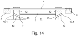
- the guide surface is angled to a base when viewed in the conveying direction, preferably at an angle ⁇ between 10° and 60°, and in particular is designed to slope down towards the center of the screen belt unit.
- ⁇ between 10° and 60°
- the guide surface is angled to a base when viewed in the conveying direction, preferably at an angle ⁇ between 10° and 60°, and in particular is designed to slope down towards the center of the screen belt unit.
- the guide surface can be provided with a profile to produce a point-variable distance, i.e. a point-variable screen belt pitch, which can be present in sections or on the entire guide surface of the positioning element for example for short pulses to support cleaning purposes.
- Profiling can influence the distance between the screen bars or the angular position of the flap units during operation, which in turn leads to a short-term, pulse-like raising or lowering of the transported mixture.
- a cleaning effect can be supported in a simple way by means of a shaking movement induced in this way.
- the sieve bars can be provided with a plastic coating with dampening properties, particularly - but not exclusively - to protect the crop.
- Several sieve bars of a flap or sieve bar unit can also be provided with one and the same covering, so that the distances between the sieve bars of a sieve bar unit are reduced to zero.
- the guide surface is part of a guide rail that is at least partially designed as a wearing part.
- the guide rail is provided with a plastic layer, for example made of polyurethane, or is even made entirely of plastic.
- a screen bar is understood to be a bar of any cross-section stretched between the endless supports.
- the cross-section can be round, non-round and, in particular, flatter.
- the positioning means according to the embodiment according to the invention is assigned at least one actuator, via which the distance of at least one part of the positioning means guiding the flap unit to the endless carrier can be adjusted. In particular, this at least the distance of the guide surface to the endless carrier varies. This distance then determines the angular position of the flap unit connected to the endless carrier, whereby the positioning means can rest on one or more parts of the flap unit, in particular comprising a joint part and/or a sieve rod. Threaded rods are preferred as actuators for adjustment, in particular manual or controlled by stepper motors. Alternatively or additionally, hydraulically or pneumatically or generally electric motor-operated actuators can be used. These can be actuated in particular via a control or control and evaluation device belonging to the machine control system and in particular integrated into it.
- a knocking sound which supports the sieving can be generated by means of an associated control or control and evaluation device.
- a positioning means is arranged on both the left and right ends of the respective screen bar units, so that uniform guidance of the movable screen bars is achieved. Irrespective of a possibly partially integral connection of the positioning means to a guide of the respective endless carrier on the frame side, a part of the positioning means that guides the screen bar units is arranged at a distance from the endless carrier.
- the positioning means can advantageously be designed in several parts along the screening zone so that the greatest possible variability is available in the spacing of the guide surface in particular from the endless carrier.
- the guide surface can then also be designed in several parts and can follow changes in the pitch of the screening belt.
- a screen belt unit according to the invention provided with flap units can also be used in an ascending area of the screen belt by setting a certain angular position of the flap units to form conveyor pockets in the screen belt, while in more horizontally running conveyor sections the focus can be on the screening function.
- the screen belt area with a screening function in the foreground other and in particular also varying distances of the guide surface to the endless carrier and associated different angular positions of the flap units and screen bar spacings can be set.
- a screen belt unit according to the invention can thus have different focus functions along its screening zone in the upper run.
- the screen belt unit according to the invention also has, in particular, several adjusting means in the case of a multi-part positioning means.
- the screen bar units according to the invention can have a slight change in the distances between the screen bars, for example via elongated holes, it is To avoid undesired positions and to define precise distances, it is advantageous if the screen bars of a screen bar unit have a fixed distance from each other, apart from any existing bearing play.
- a sieve bar of a respective sieve bar unit is fixed to the endless supports and forms part of two joints for connecting the flap unit.
- a swivel or rotary joint can be formed in a simple manner, which enables a movable sieve bar arranged parallel to the fixed sieve bar via the swivel or rotary joint parts. It makes sense for the sieve bar unit to have a rotary or swivel joint towards both outer endless supports.
- the sieve bar fixed to the endless support then forms the axis of rotation of the flap unit.
- two swiveling sieve bars forming the flap unit can be mounted on one another and via a bent connection that does not form a sieve bar in a swivel bearing or rotary bearing of the respective endless supports.
- the guide surface is part of a guide rail which, as a structurally relatively simple component, can be mounted to a frame of the sieve belt or a machine frame by installing a sieve belt unit according to the invention in a harvesting machine and in particular can be subsequently attached.
- the positioning means can also be at least partially be designed to run along.
- the rotational speed of the positioning means which can also be designed in the shape of a belt, for example, would be set to the rotational speed of the screen belt.
- the positioning means would then also be designed to be variable in distance from the screen belt using appropriate positioning means.
- a sieve belt unit according to the invention is further provided with a sieve belt, which is provided with at least 50% sieve bars designed to be positionally variable relative to the endless support.
- every second sieve bar can be designed to be stationary, while a flap unit with a sieve bar that can be moved at a fixed distance but pivotally around the stationary sieve bar is arranged on each stationary sieve bar.
- Designs of the sieve belt unit according to the invention can preferably design up to 3 of 4, i.e. 75%, of the sieve bars to be positionally variable, so that advantageous designs of the flap unit with two sieve bars that can be pivoted around a stationary sieve bar or with three pivotable sieve bars can be used.
- the preferred embodiments of the invention are provided with flap units which, at least within a certain range, can freely pivot or rotate about a rotation axis which is fixed relative to the endless supports and in particular the fixed Sieve bars are.
- one or more guide units can be provided in these areas, which are arranged in addition to the positioning means and in particular, viewed in a transverse direction, outside the area delimited by the endless carrier.
- These are preferably already known weed intake rollers that prevent any flap units that pivot due to centrifugal force from folding over in the relevant area at the front in the direction of travel.
- a guide surface of the positioning means and an outer surface of a flap unit intended to rest against it are designed in parallel in order to achieve good guidance and a cleaning effect on areas of the positioning means that become dirty during operation due to admixtures.
- An exemplary flap unit comprises a screen bar and has at least one joint part designed for detachable attachment to another screen bar of a previously or subsequently described screen belt unit, wherein the joint part or the screen bar of the flap unit has an outer surface designed for contact with a positioning means.
- the joint part can be part of a film hinge or a rotary joint.
- the positioning means preferably has an outer surface and guide surface provided with a plastic coating
- the flap unit can advantageously have a The contact positions have a surface designed parallel to this, which ensures the best possible guidance.
- the widths of the guide surface are advantageously matched to the width of the contact surfaces of the flap unit in such a way that they only differ in width by a few centimeters ( ⁇ 10 centimeters). This means that only a small amount of debris can be deposited on the guide surfaces of a positioning device and the guide surfaces are simultaneously cleaned during operation by the peripheral outer surfaces of the flap unit in the upper run.
- the joint part is at least two-part and designed to accommodate the additional screen bar of the screen belt unit, so that individual damaged or worn flap units can be easily replaced.
- the joint part is then part of a rotary joint.
- a push and/or locking element is provided for pivotally fixing the joint part, in particular to a screen bar that is firmly connected to an endless carrier, so that the attachment and disassembly of a flap unit is as simple and quick as possible.
- the joint parts provided for mounting on a sieve bar are preferably designed as joint shells and can either be provided in one piece with the positionally adjustable cross or sieve bar or have corresponding receiving areas for conventional sieve bars.
- An exemplary screen belt has at least two endless supports, preferably designed as carrier belts or chains, between which screen bars are arranged in a direction transverse to the conveying direction, with a plurality of the flap units described above or below being present.
- such a screen belt which also has the respective advantages described above and below, is formed entirely by screen bar units comprising a corresponding flap unit.
- a harvesting machine comprising a sieve belt unit as described above or below.
- This machine has the advantages of the sieve belt unit as described above and below.
- this harvesting machine has the means necessary for operating the sieve belt unit according to the invention, such as guide rollers or discs, drive means, frame or other supporting parts.
- the positioning means is fixed on the frame side and can act on the movable sieve bars via at least one correspondingly supported actuator.
- the harvesting machine has a sensor for detecting the inclination of the ground and an associated evaluation and control device, wherein the harvesting machine is designed with its evaluation device to control the positioning means depending on the inclination of the ground, in particular when viewed in the direction of travel.
- Inclination sensors in particular can be used as sensors for detecting the inclination of the ground.
- the inclination of the ground can be determined additionally or alternatively using one or more other sensors, e.g. using a GPS or similar position sensor in conjunction with a soil map stored locally in the control and evaluation device or externally on a server.
- the control and evaluation device includes standard IT resources that are used in harvesting machines. It is preferably integrated into the machine control system.
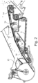
- a screen belt unit 1 comprises Fig. 1 a sieve belt 2, which is intended for sieving impurities from a mixture of crop and impurities.
- the sieve belt 2 has two endless supports 3 designed as carrier belts, between which sieve bars 4 and 6 are arranged in a direction transverse to the conveying direction.
- the conveying direction F has different gradients compared to a horizontal (not shown) over the course of a sieve zone S formed by the upper run of the sieve belt 2. These gradients arise due to the positioning of deflection rollers or disks 7, some of which can be designed as drive disks.
- a tension roller 8 tensions the sieve belt 2 against a drive disk 9, so that depending on the set gradient of the sieve belt, there is sufficient contact with the drive roller 9 in the individual sieve belt zones.
- sieve bar units 11 which has a sieve bar 4 fixed to the sieve belt 2 and a sieve bar 6 articulated thereto including an associated joint part 12.
- the sieve bars 6 are fixed so that they can move relative to the endless supports 3 via the rotary or swivel joints formed between and through the sieve bars 4.
- a number of positioning means 13 are arranged along the sieve belt 2 on both the left-hand side in the conveying direction and the right-hand side in the conveying direction, which act on the movable sieve bars 6 in such a way that a distance A (cf. Fig. 9 to 11 ) and can be variably adjusted using actuators.
- the distance A can vary over the length of the screening zone in the conveying direction F.
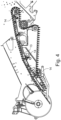
- the positioning means 13 is designed as a guide rail and in several parts, so that individual sections of guide rails 13 are created analogously to the individual pitch sections of the screen belt 2. With a plurality of associated actuators 14 ( Fig. 2 ), the individual sections or parts of the positioning element 13 can be brought into the desired relative position to the endless carrier 3. In order to be able to make the necessary adjustments in the case of different gradients of the screen belt in the course of the screen zone S, the multi-part positioning element 13 is provided with a series of push connections that can be moved by means of elongated holes.
- the individual parts of the positioning element are guided into one another and can thereby be moved towards or away from one another in order to adjust the total length of the positioning element 13 in the upper run or the corresponding Sieve zone S can be designed to be changeable.
- FIGs 2 to 4 Furthermore, usual parts of a harvesting machine according to the invention can be seen.
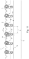
- 10 and 11 show the different screen belt pitches and distances A due to different relative positions of the positioning element 13 or parts of the positioning element 13 in relation to the endless carrier 3.
- the positioning elements 13 which are arranged at least partially between the endless carriers 3 in a plan view, from the endless carrier 3, the individual flap units of the screen bar units can assume a different angular position relative to the longitudinal extension of the endless carrier 3 or to the respective conveying direction. This changes the distance A between successive screen bars 4, 6 of different screen bar units.
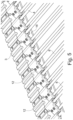
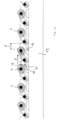
- the positioning means 13 in the screening zone is provided with a guide surface 16 on which, in the illustration of the Fig. 5 the undersides of the joint parts 12 of the flap units, which cannot be seen in more detail, comprising sieve bars 6 and the joint part 12, rest on.
- the surface 16 is provided with a plastic coating to reduce friction with the undersides of the flap units. While During operation of the screen belt unit according to the invention, the flap units are pulled over or glide along the guide surface, cleaning the guide surface of impurities falling from the upper run.
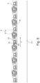
- the flap units according to the invention can be Fig. 8 have joint parts 12 at both ends, which are connected by the sieve bar 6 shown broken.
- the sieve bars 4 of a respective sieve bar unit 11 are fixed to the endless carrier, so that the sieve bar 6 is fixed in a variable position relative to the endless carrier 3 via the joint formed between the sieve bar 4 and the sieve bar 6 (cf. Fig. 5 and 6 ).
- a joint part 12 is preferably designed with two shell halves 18 ( Fig. 7 ), which are connected to one another via fastening means 15. A faulty, damaged or worn flap unit can be replaced quickly.
- the angular position of the flap unit or the screen bar unit is as shown in the Fig. 9 , 10 and 11 shown in the screening zone S by the distance of the positioning means 13 and in particular its guide surface 16 from the screen belt carrier 3.
- an angle W between a straight line 19 formed parallel to the conveying direction F and thus to the endless carrier 3 and a straight line 20 formed by the longitudinal extension of a flap unit is almost 0 ( Fig. 9 ).
- the horizontal alignment of the sieve belt 2 shown means that the joint parts 12 no longer rest on the guide surface 16 and the flap parts are pivoted open to the maximum.
- the angle W used for this is almost 90°, depending on the symmetry of the flap unit, but at least preferably between 80° and 100°.
- a roller conventionally designed as a herb intake roller which is preferably wider than the endless carrier, can be present in the deflection area ( Fig. 2 ).
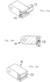
- An alternative flap unit according to the invention has a joint part 12 which has a push and/or locking element 22 for pivotally fixing the joint part, in particular to a sieve bar firmly connected to an endless carrier, by means of which the fastening and dismantling of a flap unit takes place as simply and quickly as possible ( Fig. 12 ac ).
- This joint part as well as the joint part according to the Fig. 13 ac provided with a locking and/or sliding element, which can be mounted either on the front side ( Fig. 12 a) or sideways ( Fig. 13 a) is inserted into a main part 23 of the joint part and locked there via undercuts 24 ( Fig. 12 b) or secured ( Fig. 13 b) .
- the respective locking and/or pushing element 22 is preferably made of a harder material in the area of the contact with a sieve bar than the rest of the joint part 12, so that the locking and/or pushing element 22 absorbs the essential forces acting on the flap unit and passes them on to the generally fixed sieve bar on which the flap unit is arranged.
- the locking and/or pushing element 22 forms for the preferably fixed sieve bar together with the rest of the joint part 12 a cross-section according to Fig. 12 b or Fig. 13 b
- the locking and/or sliding elements 22 of the embodiments of the Fig. 12 and 13 provided with a receptacle 24 with a half-shell shape in cross-section, the inner surface of which, together with a correspondingly shaped receptacle 25 of the main part 23, forms the bearing seat for the respective sieve bar.
- this is provided with two guide surfaces 16 which, in the cross section of the Fig. 14 and, viewed in the conveying direction, are angled to a subsoil at an angle ⁇ and are designed to slope down towards the center M of the screen belt unit.
Landscapes
- Engineering & Computer Science (AREA)
- Mechanical Engineering (AREA)
- Life Sciences & Earth Sciences (AREA)
- Environmental Sciences (AREA)
- Harvesting Machines For Root Crops (AREA)
- Belt Conveyors (AREA)
- Combined Means For Separation Of Solids (AREA)
- Chain Conveyers (AREA)
Applications Claiming Priority (2)
| Application Number | Priority Date | Filing Date | Title |
|---|---|---|---|
| DE102017124170.1A DE102017124170A1 (de) | 2017-10-17 | 2017-10-17 | Siebbandeinheit für eine Erntemaschine oder für eine Ernteguttransporteinheit, zugehörige Klappeneinheit |
| PCT/EP2018/078301 WO2019076932A2 (de) | 2017-10-17 | 2018-10-16 | Siebbandeinheit für eine erntemaschine sowie zugehörige klappeneinheit |
Publications (2)
| Publication Number | Publication Date |
|---|---|
| EP3697193A2 EP3697193A2 (de) | 2020-08-26 |
| EP3697193B1 true EP3697193B1 (de) | 2025-02-26 |
Family
ID=64184039
Family Applications (1)
| Application Number | Title | Priority Date | Filing Date |
|---|---|---|---|
| EP18799675.6A Active EP3697193B1 (de) | 2017-10-17 | 2018-10-16 | Siebbandeinheit für eine erntemaschine sowie zugehörige klappeneinheit |
Country Status (11)
| Country | Link |
|---|---|
| US (1) | US11470769B2 (uk) |
| EP (1) | EP3697193B1 (uk) |
| JP (1) | JP7109555B2 (uk) |
| CN (1) | CN111225555B (uk) |
| AU (1) | AU2018351472B2 (uk) |
| CA (1) | CA3079104C (uk) |
| DE (1) | DE102017124170A1 (uk) |
| EA (1) | EA202090903A1 (uk) |
| IL (1) | IL273941B2 (uk) |
| UA (1) | UA126819C2 (uk) |
| WO (1) | WO2019076932A2 (uk) |
Families Citing this family (17)
| Publication number | Priority date | Publication date | Assignee | Title |
|---|---|---|---|---|
| DE102018108879A1 (de) * | 2018-04-13 | 2019-10-17 | Grimme Landmaschinenfabrik Gmbh & Co. Kg | Siebbandeinheit für eine Erntemaschine oder für eine Ernteguttransporteinheit, zugehörige Klappeneinheit |
| DE102019123496B3 (de) * | 2019-09-03 | 2020-12-17 | Stefan Wöhler | Erntemaschine für Feldfrüchte |
| EP3797572B1 (en) * | 2019-09-27 | 2023-09-27 | Dewulf NV | Root crop harvester comprising an elevator for lifting root crops |
| IT201900019703A1 (it) * | 2019-10-24 | 2021-04-24 | Ecostargreen S R L | Macchina mietitrebbiatrice per la raccolta di granella da piante erbacee |
| CN110773412B (zh) * | 2019-11-28 | 2024-03-05 | 湖北科技学院 | 一种文玩核桃的选别装置 |
| DE102020112427A1 (de) | 2020-05-07 | 2021-11-11 | Grimme Landmaschinenfabrik Gmbh & Co. Kg | Hackfruchterntemaschine |
| DE102020118423A1 (de) | 2020-07-13 | 2022-01-13 | Grimme Landmaschinenfabrik Gmbh & Co. Kg | Vorrichtung zur Vereinzelung und Förderung von Hackfrüchten |
| CN112849984B (zh) * | 2021-02-20 | 2025-05-16 | 浙江京能电力设备有限公司 | 一种无电机快递分拣小车 |
| JP7499731B2 (ja) * | 2021-05-06 | 2024-06-14 | 株式会社クボタ | 農作物回収機 |
| JP7664765B2 (ja) * | 2021-06-09 | 2025-04-18 | 株式会社アイホー | 食器搬送コンベヤ |
| CN114850019B (zh) * | 2022-05-19 | 2023-05-02 | 常熟非凡新材股份有限公司 | 一种小尺寸钢球加工用的筛选装置 |
| CN115318622B (zh) * | 2022-08-31 | 2023-08-22 | 山东省农业科学院 | 一种根茎类药材初加工分级除杂装置 |
| CN115918347B (zh) * | 2022-12-29 | 2025-10-03 | 江苏大学 | 一种薯、土、茎输送分离装置和收获机 |
| DE102023109568A1 (de) * | 2023-04-17 | 2024-10-17 | Khs Gmbh | Gleitelement zum Führen eines Transportbandes |
| WO2025201811A1 (de) * | 2024-03-27 | 2025-10-02 | Khs Gmbh | Filterband für eine behälterbehandlungsanlage |
| CN118950453B (zh) * | 2024-09-06 | 2025-11-11 | 安徽省农业科学院农业机械装备与工程研究所 | 一种防卡叶的翻转式茶鲜叶过筛机 |
| CN119346261B (zh) * | 2024-12-20 | 2025-03-18 | 河北高速公路工程养护科技有限公司 | 旧沥青料破碎装置 |
Citations (2)
| Publication number | Priority date | Publication date | Assignee | Title |
|---|---|---|---|---|
| JPS4839210A (uk) * | 1971-09-20 | 1973-06-09 | ||
| EP0133886B1 (de) * | 1983-07-01 | 1988-01-07 | Deere & Company | Regelvorrichtung für die Erntebergungsvorrichtung einer Erntemaschine |
Family Cites Families (29)
| Publication number | Priority date | Publication date | Assignee | Title |
|---|---|---|---|---|
| DE3234C (de) * | 1877-11-23 | 1877-11-23 | Construction de Elevatorkette für Kartoffelgrabe-Maschinen | |
| US3061077A (en) * | 1959-07-03 | 1962-10-30 | Ralph L Noffsinger | Elevating conveyor chain |
| JPS4417154Y1 (uk) * | 1964-09-28 | 1969-07-24 | ||
| US3392819A (en) * | 1966-10-17 | 1968-07-16 | Fred L. Waite | Conveyor |
| FR2216901B1 (uk) | 1973-02-09 | 1976-05-14 | Herriau Sa | |
| DE2520605A1 (de) | 1975-05-09 | 1976-11-18 | Helmut E Klinkicht | Siebstabband fuer foerderer |
| JPS5222480U (uk) | 1975-08-04 | 1977-02-17 | ||
| JPS5438289U (uk) * | 1977-02-28 | 1979-03-13 | ||
| DE2715108A1 (de) | 1977-04-04 | 1978-10-12 | Grimme Landmaschf Franz | Siebband fuer hackfrucht-erntemaschinen, insbesondere kartoffelerntemaschinen |
| JPS57109590A (en) | 1980-12-26 | 1982-07-08 | Sumitomo Heavy Ind Ltd | Manufacture of flange material |
| DE3109209C2 (de) | 1981-03-11 | 1985-12-12 | Franz Grimme Landmaschinenfabrik Gmbh & Co Kg, 2845 Damme | Kartoffelerntemaschine |
| JPS6137017A (ja) * | 1984-07-30 | 1986-02-21 | 広島県 | 堀取機のロツトコンベヤ機構 |
| DE3429004A1 (de) | 1984-08-07 | 1986-02-20 | Gummi-Jäger KG GmbH & Cie, 3000 Hannover | Endlosverbindung fuer siebstabbaender |
| JPS62195215A (ja) * | 1986-02-21 | 1987-08-28 | 松山株式会社 | 農作業機用コンベヤ装置 |
| US4787461A (en) | 1987-06-05 | 1988-11-29 | Rogus Thomas E | Shaker assembly |
| EP0312629B1 (de) * | 1987-10-21 | 1991-05-15 | Franz Grimme Landmaschinenfabrik GmbH & Co. KG. | Siebkettenförderband |
| DE3903475A1 (de) * | 1988-05-04 | 1989-11-16 | Jaeger Arnold | Stabband fuer stabbandfoerderer |
| US5213219A (en) * | 1991-04-24 | 1993-05-25 | Griffin Horace D | Crop cleaner and separator |
| US5697451A (en) * | 1995-12-21 | 1997-12-16 | Nicholson Farm Machinery Co. Ltd. | Crop cleaner |
| DE20011436U1 (de) | 2000-07-06 | 2000-10-19 | Artemis Kautschuk- und Kunststofftechnik GmbH & Cie, 30559 Hannover | Stab für Stabbänder an landwirtschaftlichen Maschinen |
| DE102004045487A1 (de) * | 2004-09-20 | 2006-04-13 | Verhülsdonk, Walter | Stufenlos-Verstellbares Sieb-Enterder-Größensortierband |
| JP5487248B2 (ja) | 2012-06-08 | 2014-05-07 | 株式会社和光札幌 | 作物整列機構およびそれを用いた作物選別装置 |
| US9440793B2 (en) * | 2012-12-27 | 2016-09-13 | Mayekawa Mfg. Co., Ltd. | Conveyor device for conveying food |
| US9033138B2 (en) | 2013-06-12 | 2015-05-19 | Arnold Jäger Holding GmbH | Rod belt for a rod belt conveyor for agricultural machinery |
| US9033139B2 (en) | 2013-06-12 | 2015-05-19 | Arnold Jäger Holding GmbH | Rod belt for a rod belt conveyor for agricultural machinery |
| US20160066501A1 (en) * | 2014-09-04 | 2016-03-10 | Wayde Altendorf | Potato harvester chain conveyor with sleeves |
| JP6501548B2 (ja) | 2015-02-16 | 2019-04-17 | 株式会社クボタ | 収穫機 |
| UA114168U (xx) | 2016-10-07 | 2017-02-27 | Прутковий конвеєр | |
| DE102018108879A1 (de) * | 2018-04-13 | 2019-10-17 | Grimme Landmaschinenfabrik Gmbh & Co. Kg | Siebbandeinheit für eine Erntemaschine oder für eine Ernteguttransporteinheit, zugehörige Klappeneinheit |
-
2017
- 2017-10-17 DE DE102017124170.1A patent/DE102017124170A1/de not_active Withdrawn
-
2018
- 2018-10-16 US US16/755,696 patent/US11470769B2/en active Active
- 2018-10-16 UA UAA202002725A patent/UA126819C2/uk unknown
- 2018-10-16 EP EP18799675.6A patent/EP3697193B1/de active Active
- 2018-10-16 AU AU2018351472A patent/AU2018351472B2/en active Active
- 2018-10-16 CA CA3079104A patent/CA3079104C/en active Active
- 2018-10-16 CN CN201880067691.3A patent/CN111225555B/zh active Active
- 2018-10-16 IL IL273941A patent/IL273941B2/en unknown
- 2018-10-16 EA EA202090903A patent/EA202090903A1/ru unknown
- 2018-10-16 WO PCT/EP2018/078301 patent/WO2019076932A2/de not_active Ceased
- 2018-10-16 JP JP2020542508A patent/JP7109555B2/ja active Active
Patent Citations (2)
| Publication number | Priority date | Publication date | Assignee | Title |
|---|---|---|---|---|
| JPS4839210A (uk) * | 1971-09-20 | 1973-06-09 | ||
| EP0133886B1 (de) * | 1983-07-01 | 1988-01-07 | Deere & Company | Regelvorrichtung für die Erntebergungsvorrichtung einer Erntemaschine |
Also Published As
| Publication number | Publication date |
|---|---|
| UA126819C2 (uk) | 2023-02-08 |
| JP7109555B2 (ja) | 2022-07-29 |
| EP3697193A2 (de) | 2020-08-26 |
| US11470769B2 (en) | 2022-10-18 |
| DE102017124170A1 (de) | 2019-04-18 |
| CN111225555B (zh) | 2022-10-25 |
| IL273941B1 (en) | 2025-02-01 |
| WO2019076932A2 (de) | 2019-04-25 |
| CN111225555A (zh) | 2020-06-02 |
| JP2020537547A (ja) | 2020-12-24 |
| IL273941A (en) | 2020-05-31 |
| CA3079104A1 (en) | 2019-04-25 |
| US20210185904A1 (en) | 2021-06-24 |
| AU2018351472B2 (en) | 2024-05-23 |
| EA202090903A1 (ru) | 2020-09-04 |
| IL273941B2 (en) | 2025-06-01 |
| CA3079104C (en) | 2023-05-23 |
| WO2019076932A3 (de) | 2019-08-15 |
| AU2018351472A1 (en) | 2020-04-23 |
Similar Documents
| Publication | Publication Date | Title |
|---|---|---|
| EP3697193B1 (de) | Siebbandeinheit für eine erntemaschine sowie zugehörige klappeneinheit | |
| EP3772886B1 (de) | Siebbandeinheit für eine erntemaschine, zugehörige klappeneinheit | |
| DE602005004446T2 (de) | Getreidereinigung im Mähdrescher | |
| DE60019899T2 (de) | Verfahren und vorrichtung zum spannen und sammeln eines an einer rundstrickmaschine hergestellten gestricks | |
| EP3014971B1 (de) | Maschine zum ernten von hackfrüchten | |
| EP2871925A1 (de) | Pflückeinheit, erntevorsatz und erntemaschine für mais oder dergleichen | |
| EP2604104B1 (de) | Erntemaschine für Kartoffeln, Rüben o. dgl. Erntegut | |
| DE2830163C3 (de) | Reinigungsvorrichtung für Mähdrescher | |
| DE102015112580A1 (de) | Erntegutbergungseinrichtung | |
| AT502689A2 (de) | Erntemaschine | |
| DE112014006623B4 (de) | Zuführungsband für eine Zuckerrohrerntemaschine | |
| EP1817951B1 (de) | Mähdrescher mit Hordenschüttler | |
| DE10142436B4 (de) | Erntemaschine für Hackfrüchte, insbesondere Kartoffeln | |
| DE3725712C2 (uk) | ||
| EP0230261B1 (de) | Anbauvorrichtung für Mähdrescher zum Verteilen von Spreu und Kurzstroh | |
| DE102007003195A1 (de) | Erntemaschine | |
| DE102019123496B3 (de) | Erntemaschine für Feldfrüchte | |
| DE3219289C2 (de) | Zerkleinerungsvorrichtung | |
| DE2840016B1 (de) | Sortiermaschine,insbesondere zur Quadratsortierung von landwirtschaftlichen Produkten | |
| DE202007015437U1 (de) | Schubwendetrockner mit Zentralschmierung | |
| DE3140143A1 (de) | Dreschkorbanordnung in einer axialdreschmaschine | |
| DE929219C (de) | Vorrichtung zum Aussichten von Koernern von annaehernd kugeliger Gestalt mittels eines Foerderbandes | |
| EP3210461A1 (de) | Verfahren zum betreiben einer reinigungseinrichtung für einen mähdrescher | |
| DE102014006948A1 (de) | Trennvorrichtung für eine Kartoffelerntemaschine | |
| DE102014006949A1 (de) | Trennvorrichtung für eine Kartoffelerntemaschine |
Legal Events
| Date | Code | Title | Description |
|---|---|---|---|
| STAA | Information on the status of an ep patent application or granted ep patent |
Free format text: STATUS: UNKNOWN |
|
| STAA | Information on the status of an ep patent application or granted ep patent |
Free format text: STATUS: THE INTERNATIONAL PUBLICATION HAS BEEN MADE |
|
| PUAI | Public reference made under article 153(3) epc to a published international application that has entered the european phase |
Free format text: ORIGINAL CODE: 0009012 |
|
| STAA | Information on the status of an ep patent application or granted ep patent |
Free format text: STATUS: REQUEST FOR EXAMINATION WAS MADE |
|
| 17P | Request for examination filed |
Effective date: 20200429 |
|
| AK | Designated contracting states |
Kind code of ref document: A2 Designated state(s): AL AT BE BG CH CY CZ DE DK EE ES FI FR GB GR HR HU IE IS IT LI LT LU LV MC MK MT NL NO PL PT RO RS SE SI SK SM TR |
|
| AX | Request for extension of the european patent |
Extension state: BA ME |
|
| DAV | Request for validation of the european patent (deleted) | ||
| DAX | Request for extension of the european patent (deleted) | ||
| RIN1 | Information on inventor provided before grant (corrected) |
Inventor name: GERDES, JOSEF Inventor name: ROSS, JULIAN Inventor name: HOENEMANN, HEINRICH Inventor name: HALBRUEGGE, CHRISTOPH |
|
| STAA | Information on the status of an ep patent application or granted ep patent |
Free format text: STATUS: EXAMINATION IS IN PROGRESS |
|
| 17Q | First examination report despatched |
Effective date: 20220719 |
|
| GRAP | Despatch of communication of intention to grant a patent |
Free format text: ORIGINAL CODE: EPIDOSNIGR1 |
|
| STAA | Information on the status of an ep patent application or granted ep patent |
Free format text: STATUS: GRANT OF PATENT IS INTENDED |
|
| GRAS | Grant fee paid |
Free format text: ORIGINAL CODE: EPIDOSNIGR3 |
|
| INTG | Intention to grant announced |
Effective date: 20241009 |
|
| GRAA | (expected) grant |
Free format text: ORIGINAL CODE: 0009210 |
|
| STAA | Information on the status of an ep patent application or granted ep patent |
Free format text: STATUS: THE PATENT HAS BEEN GRANTED |
|
| AK | Designated contracting states |
Kind code of ref document: B1 Designated state(s): AL AT BE BG CH CY CZ DE DK EE ES FI FR GB GR HR HU IE IS IT LI LT LU LV MC MK MT NL NO PL PT RO RS SE SI SK SM TR |
|
| REG | Reference to a national code |
Ref country code: GB Ref legal event code: FG4D Free format text: NOT ENGLISH |
|
| REG | Reference to a national code |
Ref country code: CH Ref legal event code: EP |
|
| REG | Reference to a national code |
Ref country code: DE Ref legal event code: R096 Ref document number: 502018015608 Country of ref document: DE |
|
| REG | Reference to a national code |
Ref country code: IE Ref legal event code: FG4D Free format text: LANGUAGE OF EP DOCUMENT: GERMAN |
|
| REG | Reference to a national code |
Ref country code: NL Ref legal event code: FP |
|
| PG25 | Lapsed in a contracting state [announced via postgrant information from national office to epo] |
Ref country code: RS Free format text: LAPSE BECAUSE OF FAILURE TO SUBMIT A TRANSLATION OF THE DESCRIPTION OR TO PAY THE FEE WITHIN THE PRESCRIBED TIME-LIMIT Effective date: 20250526 |
|
| PG25 | Lapsed in a contracting state [announced via postgrant information from national office to epo] |
Ref country code: FI Free format text: LAPSE BECAUSE OF FAILURE TO SUBMIT A TRANSLATION OF THE DESCRIPTION OR TO PAY THE FEE WITHIN THE PRESCRIBED TIME-LIMIT Effective date: 20250226 |
|
| PG25 | Lapsed in a contracting state [announced via postgrant information from national office to epo] |
Ref country code: PL Free format text: LAPSE BECAUSE OF FAILURE TO SUBMIT A TRANSLATION OF THE DESCRIPTION OR TO PAY THE FEE WITHIN THE PRESCRIBED TIME-LIMIT Effective date: 20250226 |
|
| PG25 | Lapsed in a contracting state [announced via postgrant information from national office to epo] |
Ref country code: ES Free format text: LAPSE BECAUSE OF FAILURE TO SUBMIT A TRANSLATION OF THE DESCRIPTION OR TO PAY THE FEE WITHIN THE PRESCRIBED TIME-LIMIT Effective date: 20250226 |
|
| REG | Reference to a national code |
Ref country code: LT Ref legal event code: MG9D |
|
| PG25 | Lapsed in a contracting state [announced via postgrant information from national office to epo] |
Ref country code: IS Free format text: LAPSE BECAUSE OF FAILURE TO SUBMIT A TRANSLATION OF THE DESCRIPTION OR TO PAY THE FEE WITHIN THE PRESCRIBED TIME-LIMIT Effective date: 20250626 Ref country code: NO Free format text: LAPSE BECAUSE OF FAILURE TO SUBMIT A TRANSLATION OF THE DESCRIPTION OR TO PAY THE FEE WITHIN THE PRESCRIBED TIME-LIMIT Effective date: 20250526 |
|
| PG25 | Lapsed in a contracting state [announced via postgrant information from national office to epo] |
Ref country code: HR Free format text: LAPSE BECAUSE OF FAILURE TO SUBMIT A TRANSLATION OF THE DESCRIPTION OR TO PAY THE FEE WITHIN THE PRESCRIBED TIME-LIMIT Effective date: 20250226 |
|
| PG25 | Lapsed in a contracting state [announced via postgrant information from national office to epo] |
Ref country code: LV Free format text: LAPSE BECAUSE OF FAILURE TO SUBMIT A TRANSLATION OF THE DESCRIPTION OR TO PAY THE FEE WITHIN THE PRESCRIBED TIME-LIMIT Effective date: 20250226 Ref country code: PT Free format text: LAPSE BECAUSE OF FAILURE TO SUBMIT A TRANSLATION OF THE DESCRIPTION OR TO PAY THE FEE WITHIN THE PRESCRIBED TIME-LIMIT Effective date: 20250626 |
|
| PG25 | Lapsed in a contracting state [announced via postgrant information from national office to epo] |
Ref country code: BG Free format text: LAPSE BECAUSE OF FAILURE TO SUBMIT A TRANSLATION OF THE DESCRIPTION OR TO PAY THE FEE WITHIN THE PRESCRIBED TIME-LIMIT Effective date: 20250226 Ref country code: GR Free format text: LAPSE BECAUSE OF FAILURE TO SUBMIT A TRANSLATION OF THE DESCRIPTION OR TO PAY THE FEE WITHIN THE PRESCRIBED TIME-LIMIT Effective date: 20250527 |
|
| PG25 | Lapsed in a contracting state [announced via postgrant information from national office to epo] |
Ref country code: SE Free format text: LAPSE BECAUSE OF FAILURE TO SUBMIT A TRANSLATION OF THE DESCRIPTION OR TO PAY THE FEE WITHIN THE PRESCRIBED TIME-LIMIT Effective date: 20250226 |
|
| PG25 | Lapsed in a contracting state [announced via postgrant information from national office to epo] |
Ref country code: SM Free format text: LAPSE BECAUSE OF FAILURE TO SUBMIT A TRANSLATION OF THE DESCRIPTION OR TO PAY THE FEE WITHIN THE PRESCRIBED TIME-LIMIT Effective date: 20250226 |
|
| PG25 | Lapsed in a contracting state [announced via postgrant information from national office to epo] |
Ref country code: DK Free format text: LAPSE BECAUSE OF FAILURE TO SUBMIT A TRANSLATION OF THE DESCRIPTION OR TO PAY THE FEE WITHIN THE PRESCRIBED TIME-LIMIT Effective date: 20250226 |
|
| PG25 | Lapsed in a contracting state [announced via postgrant information from national office to epo] |
Ref country code: IT Free format text: LAPSE BECAUSE OF FAILURE TO SUBMIT A TRANSLATION OF THE DESCRIPTION OR TO PAY THE FEE WITHIN THE PRESCRIBED TIME-LIMIT Effective date: 20250226 |
|
| PG25 | Lapsed in a contracting state [announced via postgrant information from national office to epo] |
Ref country code: CZ Free format text: LAPSE BECAUSE OF FAILURE TO SUBMIT A TRANSLATION OF THE DESCRIPTION OR TO PAY THE FEE WITHIN THE PRESCRIBED TIME-LIMIT Effective date: 20250226 Ref country code: EE Free format text: LAPSE BECAUSE OF FAILURE TO SUBMIT A TRANSLATION OF THE DESCRIPTION OR TO PAY THE FEE WITHIN THE PRESCRIBED TIME-LIMIT Effective date: 20250226 |
|
| PG25 | Lapsed in a contracting state [announced via postgrant information from national office to epo] |
Ref country code: RO Free format text: LAPSE BECAUSE OF FAILURE TO SUBMIT A TRANSLATION OF THE DESCRIPTION OR TO PAY THE FEE WITHIN THE PRESCRIBED TIME-LIMIT Effective date: 20250226 |
|
| PG25 | Lapsed in a contracting state [announced via postgrant information from national office to epo] |
Ref country code: SK Free format text: LAPSE BECAUSE OF FAILURE TO SUBMIT A TRANSLATION OF THE DESCRIPTION OR TO PAY THE FEE WITHIN THE PRESCRIBED TIME-LIMIT Effective date: 20250226 |
|
| PGFP | Annual fee paid to national office [announced via postgrant information from national office to epo] |
Ref country code: NL Payment date: 20251023 Year of fee payment: 8 |
|
| REG | Reference to a national code |
Ref country code: DE Ref legal event code: R097 Ref document number: 502018015608 Country of ref document: DE |
|
| PLBE | No opposition filed within time limit |
Free format text: ORIGINAL CODE: 0009261 |
|
| STAA | Information on the status of an ep patent application or granted ep patent |
Free format text: STATUS: NO OPPOSITION FILED WITHIN TIME LIMIT |
|
| REG | Reference to a national code |
Ref country code: DE Ref legal event code: R081 Ref document number: 502018015608 Country of ref document: DE Owner name: GRIMME LANDMASCHINENFABRIK SE & CO. KG, DE Free format text: FORMER OWNER: GRIMME LANDMASCHINENFABRIK GMBH & CO. KG, 49401 DAMME, DE |
|
| PGFP | Annual fee paid to national office [announced via postgrant information from national office to epo] |
Ref country code: DE Payment date: 20251020 Year of fee payment: 8 |
|
| PGFP | Annual fee paid to national office [announced via postgrant information from national office to epo] |
Ref country code: GB Payment date: 20251024 Year of fee payment: 8 |
|
| PGFP | Annual fee paid to national office [announced via postgrant information from national office to epo] |
Ref country code: FR Payment date: 20251029 Year of fee payment: 8 |
|
| PGFP | Annual fee paid to national office [announced via postgrant information from national office to epo] |
Ref country code: BE Payment date: 20251022 Year of fee payment: 8 |
|
| 26N | No opposition filed |
Effective date: 20251127 |
|
| REG | Reference to a national code |
Ref country code: NL Ref legal event code: PD Owner name: GRIMME LANDMASCHINENFABRIK SE & CO. KG; DE Free format text: DETAILS ASSIGNMENT: CHANGE OF OWNER(S), CHANGE OF LEGAL ENTITY; FORMER OWNER NAME: GRIMME LANDMASCHINENFABRIK GMBH & CO. KG Effective date: 20260323 |