EP3697196B1 - Élément de coupe doté d'une coupe tractée - Google Patents
Élément de coupe doté d'une coupe tractée Download PDFInfo
- Publication number
- EP3697196B1 EP3697196B1 EP18793375.9A EP18793375A EP3697196B1 EP 3697196 B1 EP3697196 B1 EP 3697196B1 EP 18793375 A EP18793375 A EP 18793375A EP 3697196 B1 EP3697196 B1 EP 3697196B1
- Authority
- EP
- European Patent Office
- Prior art keywords
- guiding surface
- cutting element
- guide surface
- implement according
- blade
- Prior art date
- Legal status (The legal status is an assumption and is not a legal conclusion. Google has not performed a legal analysis and makes no representation as to the accuracy of the status listed.)
- Active
Links
Images


Classifications
-
- A—HUMAN NECESSITIES
- A01—AGRICULTURE; FORESTRY; ANIMAL HUSBANDRY; HUNTING; TRAPPING; FISHING
- A01D—HARVESTING; MOWING
- A01D34/00—Mowers; Mowing apparatus of harvesters
- A01D34/835—Mowers; Mowing apparatus of harvesters specially adapted for particular purposes
- A01D34/8355—Mowers; Mowing apparatus of harvesters specially adapted for particular purposes for cutting up or crushing remaining standing stalks, e.g. stubble
-
- A—HUMAN NECESSITIES
- A01—AGRICULTURE; FORESTRY; ANIMAL HUSBANDRY; HUNTING; TRAPPING; FISHING
- A01D—HARVESTING; MOWING
- A01D34/00—Mowers; Mowing apparatus of harvesters
- A01D34/01—Mowers; Mowing apparatus of harvesters characterised by features relating to the type of cutting apparatus
- A01D34/412—Mowers; Mowing apparatus of harvesters characterised by features relating to the type of cutting apparatus having rotating cutters
- A01D34/63—Mowers; Mowing apparatus of harvesters characterised by features relating to the type of cutting apparatus having rotating cutters having cutters rotating about a vertical axis
- A01D34/73—Cutting apparatus
- A01D34/736—Flail type
-
- A—HUMAN NECESSITIES
- A01—AGRICULTURE; FORESTRY; ANIMAL HUSBANDRY; HUNTING; TRAPPING; FISHING
- A01D—HARVESTING; MOWING
- A01D45/00—Harvesting of standing crops
- A01D45/02—Harvesting of standing crops of maize, i.e. kernel harvesting
- A01D45/021—Cornheaders
Definitions
- the present invention relates to an attachment for harvesting stalky stalks with a conveying device and a device for cutting stems, which is arranged in a plane below the conveying device and which has at least one cutting element rotating in a horizontal or at least approximately horizontal plane.
- a generic attachment is from the font DE 10 2015 115 100 A1 known in the form of a corn picker.
- a stalk of the stalks - such as a maize plant - runs into this attachment, the stalk is torn down by stalking rollers and the fruit stand, such as a corn cob of a maize plant, is separated from the maize stalk by the picking plates of the picking device.
- the corn cobs separated from the stalk are fed to a threshing device by a conveying device.
- the remaining corn stalk is transported further down by the stalking rollers, it can also be cut or trimmed.
- a stalk that is torn down is cut below the stalking rollers by chopping knives rotating at least approximately in a horizontal plane, which are arranged in the area of the stalking rollers.
- the rotating chopping knives cut the stalk pieces that have been transported down by the stalking rollers into even shorter stalk pieces, which are then thrown onto the field.
- the stalk pieces can then rot there.
- the rotating cutting elements are intended to split open the stubble and distribute the straw from the cut stalks on the ground.
- the rotating chopping knives not only cut the stalk pieces torn down by the stalking rollers, but also cut the protruding ends of the stubble of the maize plants that are still in the field after the stalks have been cut.
- An example of this way of working is found in Scripture DE 102 50 302 B4 .
- the remaining stubble is no longer spliced and pressed into the ground by the tires of the harvesting machine or other vehicles in the field, where it is very difficult for microorganisms to decompose them.
- a separate post-processing of stubble is necessary, in which the stubble has to be damaged after harvest so that it has rotted sufficiently before the next crop is sown. This requires additional work and the additional drive over the field compacts the soil unnecessarily.
- the cutting element has a guide surface on its outer edge which extends downward from the plane of the blade, the guide surface being inclined inwardly by an angle of incidence in the direction of rotation of the cutting element.
- the guide surface conveys the air, the biomass and other spatial bodies that are captured by the guide surface towards the axis of rotation of the rotating cutting element, that is to say inward.
- this together with the lateral guide surface forms a kind of bell or cage within its enveloping circle, in the interior of which the air, the biomass as well as other spatial bodies that have reached the effective area of the guide surface are mixed with one another.
- the bell or the cage are quasi closed upwards and to the side by the cutting element rotating at high speed with the guide surface extending downwards.
- the cutting elements are usually held in a central holder which is designed to be closed at the top.
- the air conveyed inward by the rotating guide surfaces, the biomass and the other spatial bodies that have been conveyed inward by the guide surface of a cutting element can therefore not escape upwards from the center of the interior.
- the material in the bell or cage can therefore only get out of the interior space downwards.
- the length of the guide surface is designed for the forward speed with which the harvesting machine, which carries the attachment, usually drives into the crop, as well as the rotational speed with which the cutting elements rotate.
- the length of the guide surface should be sufficient for the given forward speed and rotation speed to adequately fray and splice the stubble.
- the cut straw and other spatial bodies are carried along by the downward escaping air flow generated by the rotating guide surfaces and pressed onto the arable soil between the stubble.
- This also reduces the overpressure from the air that has accumulated inside the bell with the air flow downwards. In this way, the chopped straw is distributed more evenly on the arable land. Less material flies around in an uncontrolled manner in the working area of the header, so that the operation of the header becomes safer overall.
- a rotating cutting element as a kind of bell or cage is stronger the faster and / or the more cutting elements with guide surfaces rotate around a common axis of rotation.
- the generation of dust is significantly reduced. Due to the downward wind from the chopping device, dust-laden air is carried along by the crop flow and blown onto the arable soil together with the chopped plant residues.
- the guide surface on the rotating cutting element is not only advantageous for distributing the straw on the harvested area, it splits and smashes its structure when it hits a stubble and frays it far below the level of the blade, which, according to the state of the art, is the blade no longer would be attainable.
- the stubble After contact with the guide surface, the stubble is more easily accessible to microorganisms, which promotes rotting of the stubble.
- a single stubble can be hit several times by a guiding surface when a harvesting machine passes over it, whereby a stubble is spliced and smashed even better. There is no longer any need to rework the stubble in a further operation in the field.
- the transition from the blade plane to the guide surface runs in a rounded arc.
- a connection of the guide surface in a rounded arc is able to absorb higher force peaks than a sharp edge in the transition area. In this way, the cutting element is more resistant to contact with foreign bodies.
- the guide surface is positioned at an angle of more than 15 ° to the vertical, pointing inward on the leading edge of the blade.
- the pronounced inclination of the guide surface in relation to the direction of rotation of the cutting element results in a sufficiently large conveying and fanning effect of the guide surface.
- the air-conveying effect of the guide surface which has a considerable influence on the crop flow and the dropping of the stalk pieces on the field, is advantageous in the proposed design.
- the guide surface has an obliquely running edge on its end face pointing in the direction of rotation, which edge extends from the leading edge of the blade in the upper area falls backwards against the direction of rotation. Due to the sloping edge, the face of the guide surface does not collide with its entire surface butt against the outside of a stubble, but can increasingly move into the material of the stubble in the manner of a pulling cut without causing excessive force peaks.
- the lower edge of the guide surface slopes down from the front to the rear in relation to the plane of the blade, counter to the direction of rotation. Due to the sloping shape, the guide surface can slide onto the ground or the foreign body in the direction of rotation from front to back in the event of ground or foreign body contact. The cutting element blade is thereby lifted upwards during the rotational movement. This reduces wear and tear and the risk of breakage. As a result, the cutting element can be guided very close to the field floor by adjusting the height of the attachment. The stubble is caught by the guide surfaces very close to the ground and disintegrated.
- the guide surface has the greatest vertical extent in its rear third. Since stubble hit move downwards and to the side after initial contact with the guide surface, the rear parts of the guide surface opposite to the direction of rotation would have no or only insignificant contact with the crop if the guide surface did not extend further down in this area than in the part of the guide surface which, viewed in the direction of rotation, is formed further forward. The wear and In this way, the work performance of the control surface is better distributed over the entire area of the control surface.
- the angle of incidence of the guide surface to the blade plane in the radial direction from the pivot axis of the cutting element and in the vertical direction to the bottom is 80 ° to 100 °. If the angle of attack is exactly or approximately 90 °, the guide surface functions well.
- the end face and / or the lower edge of the guide surface have a material hardening with respect to the rest of the material of the guide surface. Since these areas of the guide surface are subject to particular stress and high wear, appropriate material hardening is advantageous.
- a replaceable wear plate is placed on the guide surface.
- Considerable wear is to be expected in the area of the guide surface, which is higher than the wear on the blades of the cutting element. Because of the wear plate, the entire cutting element does not have to be replaced if considerable wear has occurred in the area of the guide surface, but it is sufficient to replace the wear plates. As a result, the cutting elements have a longer service life overall, and the cutting elements do not have to be replaced more frequently than would be the case if they did not have any guide surfaces.
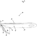
- Fig. 1 a view of a row unit 2 of an attachment is shown without the associated picking plates.
- the row unit 2 has a feed area 4 into which the stalks of the harvested crop run. Behind the intake area 4 there is a picking device 6 with which the stalks are pulled down by the rotatingly driven picking rotors. The corn cobs are plucked from the stalks on picking plates (not shown in detail in the drawing) that delimit a picking gap.
- the device 8 for cutting the stalks, which are conveyed downward with the picking device 6.
- the device 8 has one or more rotating cutting elements 10.
- the in Fig. 1 The cutting element 10 shown is shown in various rotational positions which it assumes in the course of one revolution. These cutting elements 10 cut both the stems from the stubble that remains firmly attached to the ground and the stems and leaves into smaller parts, which are carried away by the picking rotors downwards.
- the cutting elements 10 rotate in the direction of rotation R.
- the cutting elements 10 have guide surfaces 12 which extend downward from the blade plane 14.
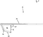
- Fig. 2 a view obliquely from below of a cutting element 10 with a guide surface 12 is shown.
- the basic rectangular shape of the blade surface is indicated by dotted lines.
- the guide surface 12 based on the front outer corner of the blade surface on which the vertical axis H is drawn, inwardly by one in the direction of rotation R of the cutting element 10
- Angle of incidence 15 is employed, the course of the angular position of the guide surface 12 in relation to the vertical axis H is indicated by a dash-dotted line.
- the guide surface 12 protrudes when the cutting element 10 rotates in the direction of rotation R into the free space that is located between the end face 20 of the guide surface 12 and the axis of rotation of the cutting element 10 below the blade plane 14 of the cutting element 10.
- the transition 16 between the blade plane 14 and the guide surface 12 is designed in the form of an arc in the exemplary embodiment.
- the end face 20 of the guide surface 12 has an obliquely running edge which falls back from the front edge 18 of the blade in the upper area towards the bottom, counter to the direction of rotation R, towards the rear.
- Fig. 3 is an end view of the in Fig. 2 shown cutting element 10 is shown.
- the lower edge 22 of the guide surface 12 slopes downwards from the front to the rear in relation to the plane of the blade 14, counter to the direction of rotation R.
- the guide surface 12 has the greatest vertical extent D in its rear third.
- the setting angle 24 of the guide surface 12 to the blade plane 14 is approximately 90 ° in the exemplary embodiment. Because of the perspective view, this angle is in Fig. 3 only recognizable on closer inspection.
- FIG Fig. 4 The approximately right angle of attack 24 between the guide surface 12 and the blade plane 14 in FIG Fig. 4 , in which a view from diagonally behind of the in the Fig. 2 and 3 cutting element shown is shown. In this view, the curved course of the transition 16 and the rearwardly sloping edge of the end face 20 can also be seen. In this view, too, the angle of incidence 15 is shown once again in dash-dotted lines, by which the guide surface 12 protrudes into the free space between the end face 20 and the axis of rotation of the cutting element 10 when the cutting element 10 rotates in the direction of rotation R.
- Fig. 5 a view from above of a cutting element 10 is shown.
- a rectangular basic shape of the cutting element 10 is indicated by dotted lines.
- the invention is not restricted to the above exemplary embodiments.
- the person skilled in the art has no difficulties in modifying the exemplary embodiments in a manner that appears suitable to him in order to adapt them to a specific application.
Landscapes
- Life Sciences & Earth Sciences (AREA)
- Environmental Sciences (AREA)
- Harvesting Machines For Specific Crops (AREA)
Claims (9)
- Appareil rapporté de récolte de produits à tige sur pied avec un dispositif de transport et un dispositif (8) agencé dans un plan en dessous du dispositif de transport pour la coupe des tiges, qui présente au moins un élément de coupe (10) périphérique tournant dans un plan horizontal ou au moins approximativement horizontal, caractérisé en ce que l'élément de coupe (10) présente au niveau de son bord extérieur une surface de guidage (12) qui s'étend depuis le plan de la lame (14) vers le bas, dans lequel la surface de guidage (12) est mise en place dans le sens de rotation (R) de l'élément de coupe (10) vers l'intérieur autour d'un angle d'incidence (15).
- Appareil rapporté selon la revendication 1, caractérisé en ce que la transition (16) du plan de la lame (14) à la surface de guidage (12) s'étend en un arc arrondi.
- Appareil rapporté selon la revendication 1 ou 2, caractérisé en ce que la surface de guidage (12) est mise en place tournée vers l'intérieur dans un angle d'incidence (15) de plus de 15° par rapport à la perpendiculaire sur l'arête avant de la lame (18).
- Appareil rapporté selon l'une des revendications précédentes, caractérisé en ce que la surface de guidage (12) au niveau de son côté avant (20) tourné dans le sens de rotation (R) présente une arête s'étendant en biais qui retombe vers l'arrière de l'arête avant de la lame (18) dans la zone supérieure vers le bas dans le sens inverse au sens de rotation (R).
- Appareil rapporté selon l'une des revendications précédentes, caractérisé en ce que l'arête inférieure (22) de la surface de guidage (12) descend vers le bas dans le sens inverse au sens de rotation (R) de l'avant vers l'arrière par rapport au plan de la lame (14).
- Appareil rapporté selon l'une des revendications précédentes, caractérisé en ce que la surface de guidage (12) présente dans son tiers arrière la plus grande étendue verticale (D).
- Appareil rapporté selon l'une des revendications précédentes, caractérisé en ce que l'angle d'incidence (24) de la surface de guidage (12) au plan de la lame (14) s'élève de 80° à 100° dans le sens radial de l'axe de pivotement de l'élément de coupe (10) et dans le sens vertical au sol.
- Appareil rapporté selon l'une des revendications précédentes, caractérisé en ce que le côté avant (20) et/ou l'arête inférieure (22) de la surface de guidage (12) par rapport au matériau restant de la surface de guidage (12) présentent un durcissement de matériau.
- Appareil rapporté selon l'une des revendications précédentes, caractérisé en ce qu'une plaque d'usure interchangeable est placée sur la surface de guidage (12).
Priority Applications (1)
| Application Number | Priority Date | Filing Date | Title |
|---|---|---|---|
| PL18793375T PL3697196T3 (pl) | 2017-10-18 | 2018-10-16 | Element ścinający z cięciem ciągnącym |
Applications Claiming Priority (2)
| Application Number | Priority Date | Filing Date | Title |
|---|---|---|---|
| DE102017124324.0A DE102017124324A1 (de) | 2017-10-18 | 2017-10-18 | Schneidelement mit ziehendem Schnitt |
| PCT/EP2018/078261 WO2019076905A1 (fr) | 2017-10-18 | 2018-10-16 | Élément de coupe doté d'une coupe tractée |
Publications (2)
| Publication Number | Publication Date |
|---|---|
| EP3697196A1 EP3697196A1 (fr) | 2020-08-26 |
| EP3697196B1 true EP3697196B1 (fr) | 2021-11-24 |
Family
ID=64017345
Family Applications (1)
| Application Number | Title | Priority Date | Filing Date |
|---|---|---|---|
| EP18793375.9A Active EP3697196B1 (fr) | 2017-10-18 | 2018-10-16 | Élément de coupe doté d'une coupe tractée |
Country Status (5)
| Country | Link |
|---|---|
| EP (1) | EP3697196B1 (fr) |
| DE (1) | DE102017124324A1 (fr) |
| HU (1) | HUE057752T2 (fr) |
| PL (1) | PL3697196T3 (fr) |
| WO (1) | WO2019076905A1 (fr) |
Families Citing this family (1)
| Publication number | Priority date | Publication date | Assignee | Title |
|---|---|---|---|---|
| CN112889456A (zh) * | 2021-01-19 | 2021-06-04 | 中国热带农业科学院热带生物技术研究所 | 木薯茎秆割取还田一体机 |
Family Cites Families (6)
| Publication number | Priority date | Publication date | Assignee | Title |
|---|---|---|---|---|
| US2891369A (en) * | 1953-07-07 | 1959-06-23 | Auto Specialties Mfg Co | Rotary shredder and cutter |
| US2815631A (en) * | 1954-09-01 | 1957-12-10 | John Deere Plow Company | Rotary mower |
| GB2000951B (en) * | 1977-07-14 | 1982-02-17 | Surridge G P | Lawn cultivating cutter assembly for rotary mower |
| DE10250302B4 (de) | 2002-10-29 | 2004-12-09 | Bayerische Motoren Werke Ag | Drallerzeugungseinrichtung für einen Verdichter |
| US20130111863A1 (en) * | 2011-11-07 | 2013-05-09 | Kondex Corporation | Disc Mower Blades |
| DE102015115100A1 (de) | 2015-09-08 | 2017-03-09 | Carl Geringhoff Gmbh & Co. Kg | Vorrichtung zur Ernte von stängeligem Halmgut |
-
2017
- 2017-10-18 DE DE102017124324.0A patent/DE102017124324A1/de not_active Withdrawn
-
2018
- 2018-10-16 HU HUE18793375A patent/HUE057752T2/hu unknown
- 2018-10-16 EP EP18793375.9A patent/EP3697196B1/fr active Active
- 2018-10-16 PL PL18793375T patent/PL3697196T3/pl unknown
- 2018-10-16 WO PCT/EP2018/078261 patent/WO2019076905A1/fr not_active Ceased
Also Published As
| Publication number | Publication date |
|---|---|
| EP3697196A1 (fr) | 2020-08-26 |
| PL3697196T3 (pl) | 2022-03-21 |
| HUE057752T2 (hu) | 2022-06-28 |
| WO2019076905A1 (fr) | 2019-04-25 |
| DE102017124324A1 (de) | 2019-04-18 |
Similar Documents
| Publication | Publication Date | Title |
|---|---|---|
| EP3272199B1 (fr) | Broyeur destiné au traitement de résidus de cultures dans un champ | |
| EP2255610B1 (fr) | Tête pour récolter des plantes en forme de tige | |
| DE102015206845B4 (de) | Schneidwerk zur Ganzpflanzenernte | |
| EP2965611B1 (fr) | Hacheur de tiges pour un appareil de moissonnage de maïs | |
| DE102007009587A1 (de) | Vorrichtung zur Einstellung der Position des Nachbeschleunigungsorgans in einer landwirtschaftlichen Erntemaschine | |
| DE102012206720A1 (de) | Maschine zur Ernte stängelartiger Pflanzen mit einem unterhalb einer Schneidscheibe angeordneten Schlagkörper zum Zerfasern der Stoppeln | |
| DE102016212621A1 (de) | Erntevorsatz mit einer Mulcheinrichtung | |
| WO2015000768A1 (fr) | Appareil agricole et procédé de traitement de chaumes végétaux | |
| EP1566092B1 (fr) | Dispositif de récolte avec broyeur | |
| DE10108505A1 (de) | Maschine zum Mähen von stängelartigem Erntegut | |
| DE102014219694A1 (de) | Maiserntegerät mit Pflanzenstoppelzieher und -häcksler | |
| DE102010028599A1 (de) | Erntegutrestehäcksel- und -verteilanordnung für einen Mähdrescher | |
| EP3697196B1 (fr) | Élément de coupe doté d'une coupe tractée | |
| DE102015220560B4 (de) | Mähdrescher mit einem zum Wechsel zwischen Schwadablagebetrieb und Häckselbetrieb in unterschiedlichen Drehrichtungen antreibbaren Strohhäcksler | |
| EP3092885B1 (fr) | Faucheuse | |
| DE102006048659A1 (de) | Maschine zur Ernte stängelartiger Pflanzen mit einem Abstreifer und einem diesem nachgeordneten Führungselement | |
| DE102016214324A1 (de) | Erntevorsatz mit einem Mulchgerät zur Bearbeitung von auf einem Feld stehenden Pflanzenstümpfen | |
| DE102007035797B4 (de) | Mäh- und Einzugseinrichtung für eine Maschine zur Ernte von stängelartigem Erntegut mit zwei wahlweise daran anbringbaren Stängelheberspitzen | |
| DE3825125C2 (fr) | ||
| DE102014118678B4 (de) | Maisgebiss für einen Feldhäcksler und Feldhäcksler | |
| DE102019007585A1 (de) | Reihenunabhängiges Vorsatzgerät zum Ernten stängelförmiger Pflanzen mit einem quer zur Fahrtrichtung liegenden, durch das ganze Vorsatzgerät durchgehenden Pflückspalt | |
| DE2436308A1 (de) | Mehrzweckgeraet zum aufnehmen, zerkleinern und verteilen von auf schwaden liegendem stroh und dergleichen | |
| EP1566091B1 (fr) | Dispositif de récolte avec un hacheur pour tiges | |
| DE102022127703A1 (de) | Erntevorsatz zur Ganzpflanzenernte | |
| DE102020133931A1 (de) | Vorsatzgerät mit Schneide- und/oder Fördereinrichtungen zum Schneiden von stängeligem Erntegut, landwirtschaftliche Arbeitsmaschine mit einem solchen Vorsatzgerät und Zerkleinerungseinrichtung für ein solches Vorsatzgerät |
Legal Events
| Date | Code | Title | Description |
|---|---|---|---|
| STAA | Information on the status of an ep patent application or granted ep patent |
Free format text: STATUS: UNKNOWN |
|
| STAA | Information on the status of an ep patent application or granted ep patent |
Free format text: STATUS: THE INTERNATIONAL PUBLICATION HAS BEEN MADE |
|
| PUAI | Public reference made under article 153(3) epc to a published international application that has entered the european phase |
Free format text: ORIGINAL CODE: 0009012 |
|
| STAA | Information on the status of an ep patent application or granted ep patent |
Free format text: STATUS: REQUEST FOR EXAMINATION WAS MADE |
|
| 17P | Request for examination filed |
Effective date: 20200330 |
|
| AK | Designated contracting states |
Kind code of ref document: A1 Designated state(s): AL AT BE BG CH CY CZ DE DK EE ES FI FR GB GR HR HU IE IS IT LI LT LU LV MC MK MT NL NO PL PT RO RS SE SI SK SM TR |
|
| AX | Request for extension of the european patent |
Extension state: BA ME |
|
| DAV | Request for validation of the european patent (deleted) | ||
| DAX | Request for extension of the european patent (deleted) | ||
| GRAP | Despatch of communication of intention to grant a patent |
Free format text: ORIGINAL CODE: EPIDOSNIGR1 |
|
| STAA | Information on the status of an ep patent application or granted ep patent |
Free format text: STATUS: GRANT OF PATENT IS INTENDED |
|
| INTG | Intention to grant announced |
Effective date: 20210617 |
|
| GRAS | Grant fee paid |
Free format text: ORIGINAL CODE: EPIDOSNIGR3 |
|
| GRAA | (expected) grant |
Free format text: ORIGINAL CODE: 0009210 |
|
| STAA | Information on the status of an ep patent application or granted ep patent |
Free format text: STATUS: THE PATENT HAS BEEN GRANTED |
|
| AK | Designated contracting states |
Kind code of ref document: B1 Designated state(s): AL AT BE BG CH CY CZ DE DK EE ES FI FR GB GR HR HU IE IS IT LI LT LU LV MC MK MT NL NO PL PT RO RS SE SI SK SM TR |
|
| REG | Reference to a national code |
Ref country code: GB Ref legal event code: FG4D Free format text: NOT ENGLISH |
|
| REG | Reference to a national code |
Ref country code: AT Ref legal event code: REF Ref document number: 1449121 Country of ref document: AT Kind code of ref document: T Effective date: 20211215 |
|
| REG | Reference to a national code |
Ref country code: DE Ref legal event code: R096 Ref document number: 502018007993 Country of ref document: DE |
|
| REG | Reference to a national code |
Ref country code: IE Ref legal event code: FG4D Free format text: LANGUAGE OF EP DOCUMENT: GERMAN |
|
| REG | Reference to a national code |
Ref country code: LT Ref legal event code: MG9D |
|
| REG | Reference to a national code |
Ref country code: NL Ref legal event code: MP Effective date: 20211124 |
|
| PG25 | Lapsed in a contracting state [announced via postgrant information from national office to epo] |
Ref country code: RS Free format text: LAPSE BECAUSE OF FAILURE TO SUBMIT A TRANSLATION OF THE DESCRIPTION OR TO PAY THE FEE WITHIN THE PRESCRIBED TIME-LIMIT Effective date: 20211124 Ref country code: LT Free format text: LAPSE BECAUSE OF FAILURE TO SUBMIT A TRANSLATION OF THE DESCRIPTION OR TO PAY THE FEE WITHIN THE PRESCRIBED TIME-LIMIT Effective date: 20211124 Ref country code: FI Free format text: LAPSE BECAUSE OF FAILURE TO SUBMIT A TRANSLATION OF THE DESCRIPTION OR TO PAY THE FEE WITHIN THE PRESCRIBED TIME-LIMIT Effective date: 20211124 Ref country code: BG Free format text: LAPSE BECAUSE OF FAILURE TO SUBMIT A TRANSLATION OF THE DESCRIPTION OR TO PAY THE FEE WITHIN THE PRESCRIBED TIME-LIMIT Effective date: 20220224 |
|
| PG25 | Lapsed in a contracting state [announced via postgrant information from national office to epo] |
Ref country code: IS Free format text: LAPSE BECAUSE OF FAILURE TO SUBMIT A TRANSLATION OF THE DESCRIPTION OR TO PAY THE FEE WITHIN THE PRESCRIBED TIME-LIMIT Effective date: 20220324 Ref country code: SE Free format text: LAPSE BECAUSE OF FAILURE TO SUBMIT A TRANSLATION OF THE DESCRIPTION OR TO PAY THE FEE WITHIN THE PRESCRIBED TIME-LIMIT Effective date: 20211124 Ref country code: PT Free format text: LAPSE BECAUSE OF FAILURE TO SUBMIT A TRANSLATION OF THE DESCRIPTION OR TO PAY THE FEE WITHIN THE PRESCRIBED TIME-LIMIT Effective date: 20220324 Ref country code: NO Free format text: LAPSE BECAUSE OF FAILURE TO SUBMIT A TRANSLATION OF THE DESCRIPTION OR TO PAY THE FEE WITHIN THE PRESCRIBED TIME-LIMIT Effective date: 20220224 Ref country code: NL Free format text: LAPSE BECAUSE OF FAILURE TO SUBMIT A TRANSLATION OF THE DESCRIPTION OR TO PAY THE FEE WITHIN THE PRESCRIBED TIME-LIMIT Effective date: 20211124 Ref country code: LV Free format text: LAPSE BECAUSE OF FAILURE TO SUBMIT A TRANSLATION OF THE DESCRIPTION OR TO PAY THE FEE WITHIN THE PRESCRIBED TIME-LIMIT Effective date: 20211124 Ref country code: HR Free format text: LAPSE BECAUSE OF FAILURE TO SUBMIT A TRANSLATION OF THE DESCRIPTION OR TO PAY THE FEE WITHIN THE PRESCRIBED TIME-LIMIT Effective date: 20211124 Ref country code: GR Free format text: LAPSE BECAUSE OF FAILURE TO SUBMIT A TRANSLATION OF THE DESCRIPTION OR TO PAY THE FEE WITHIN THE PRESCRIBED TIME-LIMIT Effective date: 20220225 |
|
| REG | Reference to a national code |
Ref country code: HU Ref legal event code: AG4A Ref document number: E057752 Country of ref document: HU |
|
| PG25 | Lapsed in a contracting state [announced via postgrant information from national office to epo] |
Ref country code: SM Free format text: LAPSE BECAUSE OF FAILURE TO SUBMIT A TRANSLATION OF THE DESCRIPTION OR TO PAY THE FEE WITHIN THE PRESCRIBED TIME-LIMIT Effective date: 20211124 Ref country code: SK Free format text: LAPSE BECAUSE OF FAILURE TO SUBMIT A TRANSLATION OF THE DESCRIPTION OR TO PAY THE FEE WITHIN THE PRESCRIBED TIME-LIMIT Effective date: 20211124 Ref country code: RO Free format text: LAPSE BECAUSE OF FAILURE TO SUBMIT A TRANSLATION OF THE DESCRIPTION OR TO PAY THE FEE WITHIN THE PRESCRIBED TIME-LIMIT Effective date: 20211124 Ref country code: ES Free format text: LAPSE BECAUSE OF FAILURE TO SUBMIT A TRANSLATION OF THE DESCRIPTION OR TO PAY THE FEE WITHIN THE PRESCRIBED TIME-LIMIT Effective date: 20211124 Ref country code: EE Free format text: LAPSE BECAUSE OF FAILURE TO SUBMIT A TRANSLATION OF THE DESCRIPTION OR TO PAY THE FEE WITHIN THE PRESCRIBED TIME-LIMIT Effective date: 20211124 Ref country code: DK Free format text: LAPSE BECAUSE OF FAILURE TO SUBMIT A TRANSLATION OF THE DESCRIPTION OR TO PAY THE FEE WITHIN THE PRESCRIBED TIME-LIMIT Effective date: 20211124 Ref country code: CZ Free format text: LAPSE BECAUSE OF FAILURE TO SUBMIT A TRANSLATION OF THE DESCRIPTION OR TO PAY THE FEE WITHIN THE PRESCRIBED TIME-LIMIT Effective date: 20211124 |
|
| REG | Reference to a national code |
Ref country code: DE Ref legal event code: R097 Ref document number: 502018007993 Country of ref document: DE |
|
| PLBE | No opposition filed within time limit |
Free format text: ORIGINAL CODE: 0009261 |
|
| STAA | Information on the status of an ep patent application or granted ep patent |
Free format text: STATUS: NO OPPOSITION FILED WITHIN TIME LIMIT |
|
| PG25 | Lapsed in a contracting state [announced via postgrant information from national office to epo] |
Ref country code: AL Free format text: LAPSE BECAUSE OF FAILURE TO SUBMIT A TRANSLATION OF THE DESCRIPTION OR TO PAY THE FEE WITHIN THE PRESCRIBED TIME-LIMIT Effective date: 20211124 |
|
| 26N | No opposition filed |
Effective date: 20220825 |
|
| PG25 | Lapsed in a contracting state [announced via postgrant information from national office to epo] |
Ref country code: SI Free format text: LAPSE BECAUSE OF FAILURE TO SUBMIT A TRANSLATION OF THE DESCRIPTION OR TO PAY THE FEE WITHIN THE PRESCRIBED TIME-LIMIT Effective date: 20211124 |
|
| PG25 | Lapsed in a contracting state [announced via postgrant information from national office to epo] |
Ref country code: MC Free format text: LAPSE BECAUSE OF FAILURE TO SUBMIT A TRANSLATION OF THE DESCRIPTION OR TO PAY THE FEE WITHIN THE PRESCRIBED TIME-LIMIT Effective date: 20211124 Ref country code: IT Free format text: LAPSE BECAUSE OF FAILURE TO SUBMIT A TRANSLATION OF THE DESCRIPTION OR TO PAY THE FEE WITHIN THE PRESCRIBED TIME-LIMIT Effective date: 20211124 |
|
| REG | Reference to a national code |
Ref country code: CH Ref legal event code: PL |
|
| GBPC | Gb: european patent ceased through non-payment of renewal fee |
Effective date: 20221016 |
|
| PG25 | Lapsed in a contracting state [announced via postgrant information from national office to epo] |
Ref country code: LU Free format text: LAPSE BECAUSE OF NON-PAYMENT OF DUE FEES Effective date: 20221016 |
|
| PG25 | Lapsed in a contracting state [announced via postgrant information from national office to epo] |
Ref country code: LI Free format text: LAPSE BECAUSE OF NON-PAYMENT OF DUE FEES Effective date: 20221031 Ref country code: CH Free format text: LAPSE BECAUSE OF NON-PAYMENT OF DUE FEES Effective date: 20221031 |
|
| PG25 | Lapsed in a contracting state [announced via postgrant information from national office to epo] |
Ref country code: IE Free format text: LAPSE BECAUSE OF NON-PAYMENT OF DUE FEES Effective date: 20221016 Ref country code: GB Free format text: LAPSE BECAUSE OF NON-PAYMENT OF DUE FEES Effective date: 20221016 |
|
| PG25 | Lapsed in a contracting state [announced via postgrant information from national office to epo] |
Ref country code: CY Free format text: LAPSE BECAUSE OF FAILURE TO SUBMIT A TRANSLATION OF THE DESCRIPTION OR TO PAY THE FEE WITHIN THE PRESCRIBED TIME-LIMIT Effective date: 20211124 |
|
| PG25 | Lapsed in a contracting state [announced via postgrant information from national office to epo] |
Ref country code: MK Free format text: LAPSE BECAUSE OF FAILURE TO SUBMIT A TRANSLATION OF THE DESCRIPTION OR TO PAY THE FEE WITHIN THE PRESCRIBED TIME-LIMIT Effective date: 20211124 |
|
| PG25 | Lapsed in a contracting state [announced via postgrant information from national office to epo] |
Ref country code: TR Free format text: LAPSE BECAUSE OF FAILURE TO SUBMIT A TRANSLATION OF THE DESCRIPTION OR TO PAY THE FEE WITHIN THE PRESCRIBED TIME-LIMIT Effective date: 20211124 |
|
| PG25 | Lapsed in a contracting state [announced via postgrant information from national office to epo] |
Ref country code: MT Free format text: LAPSE BECAUSE OF FAILURE TO SUBMIT A TRANSLATION OF THE DESCRIPTION OR TO PAY THE FEE WITHIN THE PRESCRIBED TIME-LIMIT Effective date: 20211124 |
|
| PGFP | Annual fee paid to national office [announced via postgrant information from national office to epo] |
Ref country code: PL Payment date: 20250410 Year of fee payment: 8 |
|
| PGFP | Annual fee paid to national office [announced via postgrant information from national office to epo] |
Ref country code: HU Payment date: 20251016 Year of fee payment: 8 |
|
| PGFP | Annual fee paid to national office [announced via postgrant information from national office to epo] |
Ref country code: DE Payment date: 20251020 Year of fee payment: 8 |
|
| PGFP | Annual fee paid to national office [announced via postgrant information from national office to epo] |
Ref country code: AT Payment date: 20251021 Year of fee payment: 8 |
|
| PGFP | Annual fee paid to national office [announced via postgrant information from national office to epo] |
Ref country code: FR Payment date: 20251024 Year of fee payment: 8 |
|
| PGFP | Annual fee paid to national office [announced via postgrant information from national office to epo] |
Ref country code: BE Payment date: 20251022 Year of fee payment: 8 |