EP3697251B1 - Architecture de laçage de plate-forme de chaussure automatisée - Google Patents
Architecture de laçage de plate-forme de chaussure automatisée Download PDFInfo
- Publication number
- EP3697251B1 EP3697251B1 EP18867964.1A EP18867964A EP3697251B1 EP 3697251 B1 EP3697251 B1 EP 3697251B1 EP 18867964 A EP18867964 A EP 18867964A EP 3697251 B1 EP3697251 B1 EP 3697251B1
- Authority
- EP
- European Patent Office
- Prior art keywords
- lace
- guide
- lateral
- medial
- assembly
- Prior art date
- Legal status (The legal status is an assumption and is not a legal conclusion. Google has not performed a legal analysis and makes no representation as to the accuracy of the status listed.)
- Active
Links
Images


Classifications
-
- A—HUMAN NECESSITIES
- A43—FOOTWEAR
- A43C—FASTENINGS OR ATTACHMENTS OF FOOTWEAR; LACES IN GENERAL
- A43C1/00—Shoe lacing fastenings
- A43C1/04—Shoe lacing fastenings with rings or loops
-
- A—HUMAN NECESSITIES
- A43—FOOTWEAR
- A43C—FASTENINGS OR ATTACHMENTS OF FOOTWEAR; LACES IN GENERAL
- A43C11/00—Other fastenings specially adapted for shoes
- A43C11/16—Fastenings secured by wire, bolts, or the like
- A43C11/165—Fastenings secured by wire, bolts, or the like characterised by a spool, reel or pulley for winding up cables, laces or straps by rotation
-
- A—HUMAN NECESSITIES
- A43—FOOTWEAR
- A43B—CHARACTERISTIC FEATURES OF FOOTWEAR; PARTS OF FOOTWEAR
- A43B13/00—Soles; Sole-and-heel integral units
- A43B13/14—Soles; Sole-and-heel integral units characterised by the constructive form
-
- A—HUMAN NECESSITIES
- A43—FOOTWEAR
- A43B—CHARACTERISTIC FEATURES OF FOOTWEAR; PARTS OF FOOTWEAR
- A43B23/00—Uppers; Boot legs; Stiffeners; Other single parts of footwear
- A43B23/02—Uppers; Boot legs
- A43B23/0245—Uppers; Boot legs characterised by the constructive form
- A43B23/0265—Uppers; Boot legs characterised by the constructive form having different properties in different directions
-
- A—HUMAN NECESSITIES
- A43—FOOTWEAR
- A43B—CHARACTERISTIC FEATURES OF FOOTWEAR; PARTS OF FOOTWEAR
- A43B23/00—Uppers; Boot legs; Stiffeners; Other single parts of footwear
- A43B23/26—Tongues for shoes
-
- A—HUMAN NECESSITIES
- A43—FOOTWEAR
- A43C—FASTENINGS OR ATTACHMENTS OF FOOTWEAR; LACES IN GENERAL
- A43C1/00—Shoe lacing fastenings
- A43C1/003—Zone lacing, i.e. whereby different zones of the footwear have different lacing tightening degrees, using one or a plurality of laces
-
- A—HUMAN NECESSITIES
- A43—FOOTWEAR
- A43C—FASTENINGS OR ATTACHMENTS OF FOOTWEAR; LACES IN GENERAL
- A43C11/00—Other fastenings specially adapted for shoes
- A43C11/008—Combined fastenings, e.g. to accelerate undoing or fastening
-
- A—HUMAN NECESSITIES
- A43—FOOTWEAR
- A43C—FASTENINGS OR ATTACHMENTS OF FOOTWEAR; LACES IN GENERAL
- A43C11/00—Other fastenings specially adapted for shoes
- A43C11/08—Hook fastenings; Rotary hooks
-
- A—HUMAN NECESSITIES
- A43—FOOTWEAR
- A43C—FASTENINGS OR ATTACHMENTS OF FOOTWEAR; LACES IN GENERAL
- A43C11/00—Other fastenings specially adapted for shoes
- A43C11/12—Slide or glide fastenings
-
- A—HUMAN NECESSITIES
- A43—FOOTWEAR
- A43C—FASTENINGS OR ATTACHMENTS OF FOOTWEAR; LACES IN GENERAL
- A43C3/00—Hooks for laces; Guards for hooks
-
- A—HUMAN NECESSITIES
- A43—FOOTWEAR
- A43C—FASTENINGS OR ATTACHMENTS OF FOOTWEAR; LACES IN GENERAL
- A43C7/00—Holding-devices for laces
- A43C7/08—Clamps drawn tight by laces
Definitions
- lacing architectures configurations for use in footwear including motorized or non-motorized lacing engines for centralized lace tightening.
- US 2007/240334 A1 describes an automated tightening shoe according to the preamble of claim 1, with crisscrossed laces and a tightening mechanism which operates in one direction to cause automatic tightening of the crisscrossed laces to tighten the shoe about a wearer's foot, and which can be released so that the shoe can be removed from the wearer's foot.
- the lacing architectures and lace guides discussed herein also focus on improving fit and comfort when used in conjunction with an automated lacing engine.
- the present inventors developed lacing architectures discussed herein.
- the lacing architectures and lace guides discussed herein can solve various problems experienced with centralized lace tightening mechanisms, such as uneven tightening, fit, comfort, and performance.
- One aspect of enhanced comfort involves a lacing architecture that reduces pressure across the top of the foot.
- Example lacing architectures can also enhance fit and performance by manipulating lace tension in both a medial-lateral direction as well as in an anterior-posterior (front to back) direction.
- Another example lacing architecture discussed below splits the lacing system into two zones to provide better fit, performance and comfort by separating the toe (forefoot) area from the mid-foot area.
- the lacing architectures discussed were developed specifically to interface with a modular lacing engine positioned within a mid-sole portion of a footwear assembly. However, the concepts could also be applied to motorized and manual lacing mechanisms disposed in various locations around the footwear, such as in the heel or even the toe portion of the footwear platform.
- the lacing architectures discussed include use of lace guides that can be formed from tubular plastic, metal clip, fabric loops or channels, plastic clips, and open u-shaped channels, among other shapes and materials. In some examples, various different types of lacing guides can be mixed to perform specific lace routing functions within the lacing architecture. Certain examples of specific lace guide configurations are discussed in detail below.
- the motorized lacing engine discussed below was developed from the ground up to provide a robust, serviceable, and inter-changeable component of an automated lacing footwear platform.
- the lacing engine includes unique design elements that enable retail-level final assembly into a modular footwear platform.
- the lacing engine design allows for the majority of the footwear assembly process to leverage known assembly technologies, with unique adaptions to standard assembly processes still being able to leverage current assembly resources.
- the modular automated lacing footwear platform includes a midsole plate secured to the midsole for receiving a lacing engine.
- the design of the midsole plate allows a lacing engine to be dropped into the footwear platform as late as at a point of purchase.
- the mid-sole plate, and other aspects of the modular automated footwear platform allow for different types of lacing engines to be used interchangeably.
- the motorized lacing engine discussed below could be changed out for a human-powered lacing engine.
- a fully automatic motorized lacing engine with foot presence sensing or other optional features could be accommodated within the standard mid-sole plate.
- the lacing architectures are specifically designed to assist in interfacing a lace cable (or similar lacing element) with a lacing engine.
- Lacing architectures discussed herein have been designed specifically for use with centralized lacing engines, and are designed to enable various footwear designs from casual to high-performance.
- Footwear terminology used in this disclosure includes terms such as floating textile layer, outer layer, shoe upper, bonding material, and eyestay, which are all further defined in a co-pending Application Serial Number 15/459,932 , titled "SHOE UPPER WITH FLOATING LAYER".
- the floating textile layer is a term used, in an example, to describe an inner sock-like structure that essentially floats within an outer layer of an upper portion of a footwear assembly.
- the floating textile layer can be attached to the mid-sole of the footwear assembly and may be minimally attached at select places to portions of an upper portion as well.
- the floating textile layer can be made from material with no-stretch or limited stretch properties.
- the material of the floating textile layer is a quad-axial, tri-axial, or non-woven material.
- the outer layer is a second layer of a footwear upper (or shoe upper) that covers the floating textile layer and substantially accounts for the outside shell of the shoe upper.
- the outer layer is an outer knit shell.
- the outer layer can also be made in whole or in part from polyurethane, leather, cast urethane, or digitally printed urethane as well as knit, woven, braided, or non-woven materials.
- a bonding material is typically used to reinforce portions of a footwear assembly, such as edges of the outer layer or floating textile layer, among others.
- the eyestay is a term used, in some examples, to describe an area on the footwear upper adapted to receive eyelets or lace guides. In some examples, the eyestay area can be reinforced with bonding or similar materials.
- automated footwear platform includes various components of the automated footwear platform including a motorized lacing engine, a mid-sole plate, and various other components of the platform. While much of this disclosure focuses on lacing architectures for use with a motorized lacing engine, the discussed designs are applicable to a human-powered lacing engine or other motorized lacing engines with additional or fewer capabilities. Accordingly, the term “automated” as used in “automated footwear platform” is not intended to only cover a system that operates without user input. Rather, the term “automated footwear platform” includes various electrically powered and human-powered, automatically activated and human activated mechanisms for tightening a lacing or retention system of the footwear.
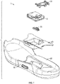
- FIG. 1 is an exploded view illustration of components of a motorized lacing system for footwear, according to some example embodiments.
- the motorized lacing system 1 illustrated in FIG. 1 includes a lacing engine 10, a lid 20, an actuator 30, a mid-sole plate 40, a mid-sole 50, and an outsole 60.
- FIG. 1 illustrates the basic assembly sequence of components of an automated lacing footwear platform.
- the motorized lacing system 1 starts with the mid-sole plate 40 being secured within the mid-sole.
- the actuator 30 is inserted into an opening in the lateral side of the mid-sole plate opposite to interface buttons that can be embedded in the outsole 60.
- the lacing engine 10 is dropped into the mid-sole plate 40.
- the lacing system 1 is inserted under a continuous loop of lacing cable and the lacing cable is aligned with a spool in the lacing engine 10 (discussed below).
- the lid 20 is inserted into grooves in the mid-sole plate 40, secured into a closed position, and latched into a recess in the mid-sole plate 40.
- the lid 20 can capture the lacing engine 10 and can assist in maintaining alignment of a lacing cable during operation.
- the footwear article or the motorized lacing system 1 includes or is configured to interface with one or more sensors that can monitor or determine a foot presence characteristic. Based on information from one or more foot presence sensors, the footwear including the motorized lacing system 1 can be configured to perform various functions.
- a foot presence sensor can be configured to provide binary information about whether a foot is present or not present in the footwear. If a binary signal from the foot presence sensor indicates that a foot is present, then the motorized lacing system 1 can be activated, such as to automatically tighten or relax (i.e., loosen) a footwear lacing cable.
- the footwear article includes a processor circuit that can receive or interpret signals from a foot presence sensor. The processor circuit can optionally be embedded in or with the lacing engine 10, such as in a sole of the footwear article.
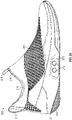
- FIGS. 2A-2C are illustrations of a fully assembled footwear assembly including automated lace tightening, according to some example embodiments.
- the footwear assembly 200 includes a mid-sole 211, an out-sole 212, a mid-sole plate 213, actuator buttons 214, a footwear upper including an outer layer 215 and a floating textile layer 216, a heel pull 217, a tongue pull 218, and a foot opening 219.
- the floating textile layer 216 only an upper edge of the floating textile layer 216 is visible, but the floating textile layer essentially lines the inside of the outer layer 215.
- the floating textile layer 216 is only secured to the outer layer 215 minimally along certain locations, such as along an eyestay, a central throat portion, or around lace guide attachment points. In some examples, the floating textile layer 216 is also (or alternatively) attached to the inside along a periphery of the mid-sole 211. Details of an example footwear construction technique that could be used to produce the footwear assembly illustrated in FIGS. 2A-2C is disclosed in the co-pending application mentioned above, Application Serial Number 15/459,932 , and will not be repeated here.
- a small outer portion of the mid-sole plate 213 is exposed through a cut-out in the mid-sole 211.
- only the actuator buttons 214 may be exposed through the side of the mid-sole 211.
- the mid-sole plate 213 is adapted to retain and protect a lacing engine within the mid-sole 211 of the footwear assembly 200.
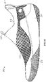
- FIG. 2B illustrates a medial view of footwear assembly 200.
- the footwear assembly 200 is depicted as including out-sole 212, mid-sole 211, outer layer 215, heel pull 217, tongue pull 218, and foot opening 219.
- the outer layer 215, in this example, is a knit outer shell covering the floating textile layer 216 and all lacing components, such as the lacing components discussed in reference to FIGS. 3A-3B below.
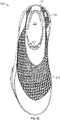
- FIG. 2C illustrates a top view of footwear assembly 200, which includes illustration of outer layer 215, floating textile layer 216, heel pull 217, foot opening 219, and a floating tongue 220.
- the floating tongue 220 can be attached only at a distal end or only at a distal end and a proximal end adjacent the foot opening 219.
- FIGS. 3A-3B are top-view diagrams illustrating a lacing architecture for use with footwear assemblies not belonging to the invention including a motorized lacing engine.
- FIG. 3A is a top-view diagram illustrating a flattened footwear upper with a lacing architecture for use with a lacing engine, according to some example embodiments.
- the footwear upper 300 has a medial side 303 and a lateral side 303, as well as a distal end and a proximal end.
- the distal end includes a toe box section 307 and the proximal end includes a heel portion.
- the footwear upper 300 also includes a floating textile layer 301, an outer layer 302, and a floating tongue 305.
- the floating tongue 305 extends out of the foot opening 309 of the outer layer 302 proximate a throat portion 311 formed from a U-shaped cut-out in at least the outer layer 302.
- the throat portion 311 can be integrated into a covered layer of the outer layer 302, so the throat portion 311 and the lacing architecture is concealed from external view.
- the throat portion 311 is also cut-out, of the floating textile layer 301.
- the outer layer 302 can include an outer layer border 320.
- the outer layer border 320 can be a bonding material or some similar reinforcing structure.
- the knit outer shell outer layer can be bonded directly to the mid-sole without an outer layer border.
- the lacing architecture comprises a series of lace guides 310 that route a lace cable 319 in a crisscross pattern over the throat portion 311.
- a crisscross lacing pattern is one that alternates between medial and lateral side lace guides across a centerline of the footwear assembly.
- the lace cable 319 can be fixed at a medial lace termination 316 and a lateral lace termination 317, which creates a lace loop that is routed by the lacing architecture to engage a lacing engine housed within a mid-sole of the footwear assembly.
- the lacing engine can be located in various locations throughout the footwear assembly, but is discussed for exemplary purposes only as being more or less centered under the arch within the mid-sole.
- the lacing architecture includes a tongue lace guide assembly 315 (or simply a tongue lace guide 315).
- the tongue lace guide 315 can include a medial facing lace guide and a lateral facing lace guide.
- the medial facing lace guide and the lateral facing lace guide can be molded or formed from a single piece of material or be separate structures coupled together in some manner.
- the medial facing lace guide and the lateral facing lace guide can be coupled together with an elastic member that allows for some separation between the lace guides upon application of tension on the lace cable 319.
- the medial facing lace guide and the lateral facing lace guide can be adhered to a tongue lace guide reinforcement 306.
- the medial facing lace guide and the lateral facing lace guide are disposed on, wrapped in, or otherwise connected via a webbing material.
- the tongue lace guide reinforcement can be a no-stretch or limited-stretch material, a rigid material, or an elastic material.
- the tongue lace guide reinforcement 306 can be adhered, stitched, or similarly affixed to the floating tongue 305.
- the tongue lace guide reinforcement 306 be padded or similarly constructed to distribute forces applied to the tongue lace guide across a wider area to avoid hot-spots for a user.
- the lacing architecture can include multiple lace guides 310 distributed around a periphery of the throat portion 311 and affixed to an eyestay 308.
- the eyestay 308 can be a reinforced portion of the outer layer 302 or a separate structure affixed to the outer layer 302.
- the eyestay 308 can be a bonding material, as noted above.
- the lace guides 310 can be stitched, adhered, or otherwise affixed to the eyestay 308.
- the eyestay 308 can include enlarged areas to receive a lace guide 310, as illustrated in FIG. 3A .
- An example lace guide structure is discussed below in reference to FIGS. 4A -4F.
- the lace guides 310 route the lace cable 319 proximally along a periphery of the throat portion 311 in a crisscross fashion. From the lace guides 310, the lace cable 319 is routed into the tongue lace guide 315, which in turn routes the lace cable 319 medially and laterally into heel lace guides 312.
- the heel lace guides 312 can be adhered or affixed to a heel counter as well as connected to a heel counter with an elastic connection or inelastic connection to distribute lace cable forces around a heel portion of the footwear assembly. From the heel lace guides 312 the lace cable 319 is routed into either a medial lace exit 318 or a lateral lace exit 319.
- the medial lace exit 318 and the lateral lace exit 319 route the lace cable 319 into a position to engage a lacing engine disposed in the mid-sole of the footwear assembly.
- the medial lace exit 318 and lateral lace exit 319 can be a molded lace guide, a fabric lace guide, a tubular lace guide, a channel molded into the mid-sole, or some similar structure capable of guiding the lace cable 319.
- FIG. 3B is a diagram illustrating a floating tongue, according to an example embodiment.
- the floating tongue 305 includes a proximal end (top of figure) and a distal end (bottom of figure) as well as a medial side and a lateral side.
- the floating tongue 305 includes a tongue outer layer 351 and a tongue inner layer 352.
- the tongue outer layer 351 can be a similar material to the outer layer 302 of the footwear upper 300.
- the tongue inner layer 352 can be a similar material to the floating textile layer 301 of the footwear upper 300.
- the tongue outer layer 351 and tongue inner layer 352 can be alternative materials and include padding or other features designed to enhance user comfort.
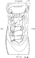
- FIG. 4A is a top-view diagram illustrating a flattened footwear upper 400 with a lacing architecture for use with a lacing engine, according to some example embodiments.
- FIG. 4B is a picture of an example footwear assembly utilizing the two-zone lacing architecture discussed in reference to FIG. 4A .
- the footwear upper 400 has a medial side 403 and a lateral side 404, as well as a distal (toe) end and a proximal (heel) end.
- the distal end includes a toe box section 407 and the proximal end includes a heel portion 406.
- the footwear upper 400 can also include a floating textile layer (optional, not illustrated), an outer layer 402, and a floating tongue 405.
- the floating tongue 405 extends out of the foot opening 409 of the outer layer 402 proximate a throat portion 411 (also referred to as a throat section) formed from a U-shaped cut-out in at least the outer layer 402.
- the throat portion 411 varies in configuration, including various cut-out shapes or alternative material sections. All throat portions allow for portions of the lateral and medial sides of the footwear assembly to move in reference to each other.
- the throat portion 411 can be integrated into a covered layer of the outer layer 402, so the throat portion 411 and the lacing architecture is concealed from external view.
- the throat portion 411 is also cut-out of the floating textile layer.
- the footwear upper 400 can include some or all of the structures discussed in reference to footwear upper 300, but is illustrated in a more simplistic fashion to emphasize the two-zone lacing architecture.
- the lacing architecture is split into two different zones.
- the first zone interacts with the toe or forefoot area of the footwear upper 400.
- the second zone interacts with the mid-foot area of the footwear upper 400.
- the first lacing zone lace cable is illustrated as a solid dark grey line, and the second lacing zone lace cable illustrated as a dotted black line.
- the lace cable in these details is a single cable running from termination 420 to termination 421 (terminations also referred to as anchor locations or anchor points).
- the material used will typically be common between the different zones.
- the first lacing zone can include lace guides guiding the lace cable 410 from a first lace termination 420.
- the first lace termination 420 is located on a distal-lateral portion of eyestay 408.
- the lace cable 410 is routed from the first lace termination 420 across a distal end of throat portion 411 and through a first medial lace guide 440. From the first medial lace guide 440 the lace cable 410 is routed back over the throat portion 411 and through a first lateral lace guide 430. From the first lateral lace guide 430, the lace cable 410 is routed pass a second lateral lace guide 431 and though a third lateral lace guide 432.
- the lace guides are label first, second, third, etc...
- the lace cable 410 can route through a material guide 422 enroute from the first lateral lace guide 430 to the third lateral lace guide 432. From the third lateral lace guide 432, the lace cable 410 is routed through a lateral facing tongue lace guide 417 and down to a lateral heel lace guide 451 through an optional material guide 422. The lateral heel lace guide 451 routes the lace cable 410 into a mid-sole plate via lateral lace exit 419.
- the second lacing zone includes a set of lace guides routing the lace cable 410 from the second termination 421 to the medial lace exit 418.
- the lace cable 410 is routed from the second termination 421 on the lateral side of eyestay 408 over the throat portion 411 to the second medial lace guide 441.
- the lace cable 410 is routed back over the throat portion 411 to the second lateral lace guide 431.
- the lace cable 410 then routes through the second lateral lace guide 431 back over the throat portion 411 for a third time and through the third medial lace guide 442.
- the third medial lace guide 442 routes the lace cable 410 on to the medial facing tongue lace guide 416, which routes the lace cable on towards the medial heel lace guide 450. Enroute to the medial heel lace guide 450 the lace cable can optionally be routed through a material lace guide 424. From the medial heel lace guide 450 the lace cable 410 is routed into the mid-sole plate via the medial lace exit 418.
- the two-zone lacing architecture enables an uneven distribution of the lace cable tension between the distal end of the throat portion 411 and the proximal end.
- the first lacing zone applies the same lace cable tension across fewer lace guides, resulting the tension being distributed across a smaller area.
- the second lacing zone distributes the lace cable tension over a larger area with more lace guides The user experiences a tighter, higher performance fit in the toe (forefoot) area of the footwear with the two-zone lacing architecture.
- Other multi-zone lacing architectures can be utilized to vary the distribution of lace cable tension as desired for a particular footwear application.
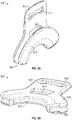
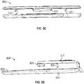
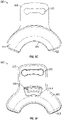
- FIGs. 5A - 5F are diagrams illustrating an example lacing guide 800 for use in certain lacing architectures, according to some example embodiments.
- an alternative lace guide with an open lace channel is illustrated.
- the lacing guide 800 described below can be substituted into any of the lacing architectures discussed above in reference to lace guide 810, heel lace guide 610, or even the medial exit guide 835. All of the various configurations discussed above will not be repeated here for the sake of brevity.
- the lacing guide 800 includes a guide tab 805, a stitch opening 810, a guide superior surface 815, a lace retainer 820, a lace channel 825, a channel radius 830, a lace access opening 840, a guide inferior surface 845, and a guide radius 850.
- Advantages of an open channel lace guide, such as lacing guide 800 include the ability to easily route the lace cable after installation of the lace guides on the footwear upper. With tubular lace guides as illustrated in many of the lace architecture examples discussed above, routing the lace cable through the lace guides is most easily accomplish before adhering the lace guides to the footwear upper (not to say it cannot be accomplished later). Open channel lace guides facilitate simple lace routing by allowing the lace cable to simply be pushed pass the lace retainer 820 after the lace guides 800 are positioned on the footwear upper.
- the lacing guide 800 can be fabricated from various materials including metal or plastics.
- the lacing guide 800 can be initially attached to a footwear upper through stitching or adhesives.
- the illustrated design includes a stitch opening 810 that is configured to enable easy manual or automated stitching of lacing guide 800 onto a footwear upper (or similar material).
- lace cable can be routed by simply pulling a loop of lace cable into the lace channel 825.
- the lace access opening 840 extends through the inferior surface 845 to provide a relief recess for the lace cable to get around the lace retainer 820.
- the lace retainer 820 can be different dimensions or even be split into multiple smaller protrusions.
- the lace retainer 820 can be narrower in width, but extend further towards or even into access opening 840.
- the access opening 840 can also be different dimensions, and will usually somewhat mirror the shape of lace retainer 820 (as illustrated in FIG. 5F ).
- the channel radius 830 is designed to correspond to, or be slightly larger then, the diameter of the lace cable.
- the channel radius 830 is one of the parameters of the lacing guide 800 that can control the amount of friction experienced by the lace cable running through the lacing guide 800.
- Another parameter of lacing guide 800 that impacts friction experienced by the lace cable includes guide radius 850.
- the guide radius 850 also may impact the frequency or spacing of lace guides positioned on a footwear upper.
- FIG. 5G is a diagram illustrating a portion of footwear upper 805 with a lacing architecture 890 using lacing guides 800, according to some example embodiments.
- multiple lacing guides 800 are arranged on a lateral side of footwear upper 805 to form half of the lacing architecture 890.
- lacing architecture 890 uses lacing guides 800 to form a wave pattern or parachute lacing pattern to route the lace cable.
- lace tightening can produce both later-medial tightening as well as anterior-posterior tightening of the footwear upper 805.
- lacing guides 800 are at least initially adhered to upper 805 through stitching 860.
- the stitching 860 is shown over or engaging stitch opening 810.
- One of the lacing guide 800 is also depicted with a reinforcement 870 covering the lacing guide.
- Such reinforcements can be positioned individually over each of the lacing guides 800. Alternatively, larger reinforcements could be used to cover multiple lacing guides.
- reinforcement 870 can be adhered through adhesives, heat-activated adhesives, and/or stitching.
- reinforcement 870 can be adhered using adhesives (heat-activated or not) and a vacuum bagging process that uniformly compresses the reinforcement over the lacing guide.
- a similar vacuum bagging process can also be used with reinforcements and lacing guides discussed above.
- mechanical presses or similar machines can be used to assist with adhering reinforcements over lacing guides.
- the lace cable can be routed through the lacing guides. Lace cable routing can begin with anchoring a first end of the lace cable at lateral anchor point 870. The lace cable can then be pulled into each lace channel 825 starting with the anterior most lacing guide and working posteriorly towards the heel of upper 805. Once the lace cable is routed through all lacing guides 800, reinforcements 870 can be optionally adhered over each of the lacing guides 800 to secure both the lacing guides and the lace cable.
Landscapes
- Footwear And Its Accessory, Manufacturing Method And Apparatuses (AREA)
- Health & Medical Sciences (AREA)
- General Health & Medical Sciences (AREA)
- Physical Education & Sports Medicine (AREA)
Claims (16)
- Ensemble article chaussant comprenant :un ensemble tige d'article chaussant (400) comprenant une couche extérieure (402) et une languette flottante (405), l'ensemble tige d'article chaussant (400) comprenant une section bout (407), un côté interne (403), un côté externe (404), une section talon et une section gorge centrale (411) ;un câble formant lacet (410) comportant une première extrémité assujettie à l'ensemble tige (400) à un premier emplacement d'assujettissement (420) et une seconde extrémité assujettie à l'ensemble tige (400) à un second emplacement d'assujettissement (421) ;une première pluralité de guides de lacet (430, 432, 440) formant une première zone de laçage acheminant une première partie du câble formant lacet (410) afin de tendre une région d'avant-pied de l'ensemble article chaussant ;une seconde pluralité de guides de lacet (431, 441, 442) formant une seconde zone de laçage acheminant une seconde partie du câble formant lacet (410) afin de tendre une région de médio-pied de l'ensemble article chaussant ;un ensemble guide de lacet de languette (415) fixé à une partie proximale de la languette flottante (405), l'ensemble guide de lacet de languette (415) étant apte à recevoir le câble formant lacet (410) à la fois depuis le côté interne (403) et depuis le côté externe (404) ;un guide de lacet de talon interne (450) placé pour recevoir le câble formant lacet (410) provenant du guide de lacet de languette (415) le long du côté interne (403) de l'ensemble tige (400) ;un guide de lacet de talon externe (451) placé pour recevoir le câble formant lacet (410) provenant du guide de lacet de languette (415) le long du côté externe (404) de l'ensemble tige (400) ;une sortie de lacet interne (418) acheminant le câble formant lacet (410) à partir du guide de lacet de talon interne (450) jusqu'à une position permettant au câble formant lacet (410) d'entrer en prise avec un moteur de laçage (10) disposé à l'intérieur d'une partie semelle intercalaire (50) de l'ensemble article chaussant ; etune sortie de lacet externe (410) destinée à acheminer le câble formant lacet (410) à partir du guide de lacet de talon externe (451) jusqu'à une position d'entrée en prise avec le moteur de laçage (10),caractérisé en ce quela seconde pluralité de guides de lacet (431, 441, 442) distribue la tension du câble formant lacet (410) sur une plus grande surface de l'ensemble article chaussant que la première pluralité de guides de lacet (430, 432, 440).
- Ensemble article chaussant selon la revendication 1, dans lequel la première pluralité de guides de lacet (430, 432, 440) comprend un guide de lacet interne (440) sur le côté interne (403) de la section gorge centrale (411) et deux guides de lacet externes (430, 432) sur le côté externe (404) de la section gorge centrale (411).
- Ensemble article chaussant selon la revendication 2, dans lequel le premier guide de lacet externe (430) des deux guides de lacet externes (430, 432) est situé vers une extrémité distale de la section gorge centrale (411) et le second guide de lacet externe (432) des deux guides de lacet externes (430, 432) est situé vers une extrémité proximale de la section gorge centrale (411).
- Ensemble article chaussant selon la revendication 3, dans lequel le chemin du câble formant lacet (410) pour la première zone de laçage comprend les segments de chemin suivants :du premier emplacement d'assujettissement (420) au guide de lacet interne (440) ;du guide de lacet interne (440) au premier guide de lacet externe (430) ; etdu premier guide de lacet externe (430) au second guide de lacet externe (432).
- Ensemble article chaussant selon la revendication 4, dans lequel le chemin du câble formant lacet (410) pour la première zone de laçage continue du second guide de lacet externe (432) à un guide de lacet orienté du côté externe (417) dans l'ensemble guide de lacet de languette (415).
- Ensemble article chaussant selon la revendication 5, dans lequel le chemin du câble formant lacet (410) pour la première zone de laçage continue du guide de lacet orienté du côté externe (417) au guide de lacet de talon externe (451).
- Ensemble article chaussant selon la revendication 1, dans lequel la seconde pluralité de guides de lacet (431, 441, 442) comprend un premier guide de lacet externe (431) disposé le long d'une partie centrale d'un côté externe (404) de la section gorge centrale (411) et une pluralité de guides de lacet internes (441, 442) répartis le long d'une longueur d'un côté interne (403) de la section gorge centrale (411).
- Ensemble article chaussant selon la revendication 7, dans lequel le chemin du câble formant lacet (410) pour la seconde zone de laçage comprend les segments de chemin suivants :du second emplacement d'assujettissement (421) à un premier guide de lacet interne (441) de la pluralité de guides de lacet internes (441, 442) ;du premier guide de lacet interne (441) au premier guide de lacet externe (431) ;du premier guide de lacet externe (431) à un second guide de lacet interne (442) de la pluralité de guides de lacet internes (441, 442).
- Ensemble article chaussant selon la revendication 8, dans lequel le chemin du câble formant lacet (410) pour la seconde zone de laçage comprend en outre un segment de chemin s'étendant du second guide de lacet interne (442) à un guide de lacet orienté du côté interne (416) dans l'ensemble guide de lacet de languette (415).
- Ensemble article chaussant selon la revendication 9, dans lequel le chemin du câble formant lacet (410) pour la seconde zone de laçage continue du guide de lacet orienté du côté interne (416) au guide de lacet de talon interne (450).
- Ensemble article chaussant selon la revendication 1, dans lequel le premier emplacement d'assujettissement (420) se trouve sur le côté externe (404) éloigné de la section gorge centrale (411), et le second emplacement d'assujettissement (421) se trouve sur le côté externe (404) adjacent au premier guide de lacet externe (430).
- Ensemble article chaussant selon l'une quelconque des revendications précédentes, dans lequel l'ensemble guide de lacet de languette (415) comprend un guide de lacet orienté du côté interne (416) à l'opposé d'un guide de lacet orienté du côté externe (417).
- Ensemble article chaussant selon la revendication 12, dans lequel l'ensemble guide de lacet de languette (415) comprend un élément élastique accouplant le guide de lacet orienté du côté interne (416) au guide de lacet orienté du côté externe.
- Ensemble article chaussant selon la revendication 12 ou 13, dans lequel l'ensemble guide de lacet de languette (415) est une structure d'un seul tenant avec un raccordement rigide entre le guide de lacet orienté du côté interne (416) et le guide de lacet orienté du côté externe (417).
- Ensemble article chaussant selon l'une quelconque des revendications précédentes, dans lequel l'ensemble guide de lacet de languette (415) est relié par fusion à un matériau de renforcement qui est cousu à la languette flottante (405).
- Ensemble article chaussant selon l'une quelconque des revendications précédentes, dans lequel le guide de lacet de talon interne (450) et le guide de lacet de talon externe (451) sont accouplés, par le biais d'un élément d'accouplement de talon, à un contrefort dans la section talon de l'ensemble tige (400), l'élément d'accouplement de talon étant un élément élastique.
Priority Applications (1)
| Application Number | Priority Date | Filing Date | Title |
|---|---|---|---|
| EP22187620.4A EP4115761B1 (fr) | 2017-10-20 | 2018-10-19 | Architecture de laçage de plate-forme de chaussure automatisée |
Applications Claiming Priority (3)
| Application Number | Priority Date | Filing Date | Title |
|---|---|---|---|
| US201762574940P | 2017-10-20 | 2017-10-20 | |
| US201862634358P | 2018-02-23 | 2018-02-23 | |
| PCT/US2018/056631 WO2019079673A1 (fr) | 2017-10-20 | 2018-10-19 | Architecture de laçage de plate-forme de chaussure automatisée |
Related Child Applications (1)
| Application Number | Title | Priority Date | Filing Date |
|---|---|---|---|
| EP22187620.4A Division EP4115761B1 (fr) | 2017-10-20 | 2018-10-19 | Architecture de laçage de plate-forme de chaussure automatisée |
Publications (3)
| Publication Number | Publication Date |
|---|---|
| EP3697251A1 EP3697251A1 (fr) | 2020-08-26 |
| EP3697251A4 EP3697251A4 (fr) | 2021-06-16 |
| EP3697251B1 true EP3697251B1 (fr) | 2022-08-03 |
Family
ID=66169060
Family Applications (2)
| Application Number | Title | Priority Date | Filing Date |
|---|---|---|---|
| EP18867964.1A Active EP3697251B1 (fr) | 2017-10-20 | 2018-10-19 | Architecture de laçage de plate-forme de chaussure automatisée |
| EP22187620.4A Active EP4115761B1 (fr) | 2017-10-20 | 2018-10-19 | Architecture de laçage de plate-forme de chaussure automatisée |
Family Applications After (1)
| Application Number | Title | Priority Date | Filing Date |
|---|---|---|---|
| EP22187620.4A Active EP4115761B1 (fr) | 2017-10-20 | 2018-10-19 | Architecture de laçage de plate-forme de chaussure automatisée |
Country Status (6)
| Country | Link |
|---|---|
| US (3) | US10856618B2 (fr) |
| EP (2) | EP3697251B1 (fr) |
| JP (1) | JP7245240B2 (fr) |
| KR (3) | KR102263035B1 (fr) |
| CN (2) | CN114652053B (fr) |
| WO (1) | WO2019079673A1 (fr) |
Families Citing this family (10)
| Publication number | Priority date | Publication date | Assignee | Title |
|---|---|---|---|---|
| US10852069B2 (en) | 2010-05-04 | 2020-12-01 | Fractal Heatsink Technologies, LLC | System and method for maintaining efficiency of a fractal heat sink |
| EP3697251B1 (fr) | 2017-10-20 | 2022-08-03 | Nike Innovate C.V. | Architecture de laçage de plate-forme de chaussure automatisée |
| CN114423307A (zh) | 2019-05-31 | 2022-04-29 | 耐克创新有限合伙公司 | 自适应支撑服装系统和方法 |
| CN113993412A (zh) * | 2019-06-19 | 2022-01-28 | 耐克创新有限合伙公司 | 具有插入元件的针织部件 |
| WO2021034784A1 (fr) | 2019-08-16 | 2021-02-25 | Poltorak Technologies, LLC | Dispositif et procédé de diagnostic médical |
| US20220110401A1 (en) * | 2020-10-13 | 2022-04-14 | Nike, Inc. | Article of Footwear |
| KR102581603B1 (ko) | 2021-11-10 | 2023-09-22 | 중앙대학교 산학협력단 | 발목 관절 가변 압박 신발 및 압박력 제어방법 |
| US12171306B2 (en) * | 2021-11-16 | 2024-12-24 | Puma SE | Article of footwear having an automatic lacing system |
| US11877624B2 (en) * | 2021-11-18 | 2024-01-23 | Shimano Inc. | Shoelace arrangement and shoelace guide for shoe |
| KR102736066B1 (ko) * | 2021-12-22 | 2024-11-29 | 주식회사 신경 | 신발의 디아이와이 와이어 가이드 장치 |
Family Cites Families (65)
| Publication number | Priority date | Publication date | Assignee | Title |
|---|---|---|---|---|
| US749569A (en) * | 1904-01-12 | Shoe-lacing | ||
| US64155A (en) | 1867-04-23 | Improved shoe-fastening | ||
| US811872A (en) * | 1904-06-18 | 1906-02-06 | Moses Ries | Lacing device. |
| US1386985A (en) * | 1920-11-30 | 1921-08-09 | Bowers George Luther | Means for securing shoe-tongues and the like |
| CH183109A (de) * | 1935-07-03 | 1936-03-15 | Testa Giovanni | Sportschuh mit Vorderschluss, insbesondere als Ski- und Bergschuh geeignet. |
| DE1190359B (de) * | 1960-04-05 | 1965-04-01 | Franz Fesl | Sportschuh, insbesondere Skischuh |
| CH562015A5 (fr) | 1972-03-21 | 1975-05-30 | Weinmann Ag | |
| IT213808Z2 (it) * | 1988-06-22 | 1990-03-01 | Olivieri Icaro & C | Allacciatura per scarponi da sci in particolare per scarponi del tipo cosidetto a calzata posteriore. |
| DE3900777C2 (de) | 1988-06-30 | 1999-06-24 | Lowa Sportschuhe Gmbh | Skistiefel (Querschlitzspanner für Rist- und Fersenseil) |
| US5177882A (en) * | 1989-06-03 | 1993-01-12 | Puma Ag Rudolf Dassler Sport | Shoe with a central fastener |
| US5791068A (en) * | 1992-07-20 | 1998-08-11 | Bernier; Rejeanne M. | Self-tightening shoe |
| FR2706744B1 (fr) * | 1993-06-21 | 1995-08-25 | Salomon Sa | |
| US5791021A (en) * | 1995-12-01 | 1998-08-11 | James; Laurence H. | Cable fastener |
| CN1068510C (zh) | 1997-07-08 | 2001-07-18 | 周龙交 | 鞋带自动穿系暨脱解复动的鞋子 |
| US7591050B2 (en) | 1997-08-22 | 2009-09-22 | Boa Technology, Inc. | Footwear lacing system |
| US20020095750A1 (en) | 1997-08-22 | 2002-07-25 | Hammerslag Gary R. | Footwear lacing system |
| US5934599A (en) * | 1997-08-22 | 1999-08-10 | Hammerslag; Gary R. | Footwear lacing system |
| US7661205B2 (en) * | 1998-03-26 | 2010-02-16 | Johnson Gregory G | Automated tightening shoe |
| US6032387A (en) * | 1998-03-26 | 2000-03-07 | Johnson; Gregory G. | Automated tightening and loosening shoe |
| US6467194B1 (en) | 1998-03-26 | 2002-10-22 | Gregory G. Johnson | Automated tightening shoe |
| US6896128B1 (en) | 1998-03-26 | 2005-05-24 | Gregory G. Johnson | Automated tightening shoe |
| US6158096A (en) * | 1999-02-24 | 2000-12-12 | Bar; Oren | Shoe tongue positioner |
| CA2329700A1 (fr) * | 2000-12-28 | 2002-06-28 | Bauer Nike Hockey Inc. | Dispositif de lacage |
| TW521593U (en) | 2002-02-08 | 2003-02-21 | Kuen-Jung Liou | Shoes capable of being tightened electrically |
| ITPD20030229A1 (it) * | 2003-10-02 | 2005-04-03 | Dolomite Spa | Calzatura con allacciatura a stringhe |
| US7281341B2 (en) * | 2003-12-10 | 2007-10-16 | The Burton Corporation | Lace system for footwear |
| DE102005036013A1 (de) | 2005-08-01 | 2007-02-08 | Eberhard Friebe | Öffnungs- und Schließvorrichtung für Schuhe |
| US7721468B1 (en) | 2005-08-26 | 2010-05-25 | Gregory G. Johnson | Tightening shoe |
| FR2891118B1 (fr) * | 2005-09-28 | 2007-12-21 | Salomon Sa | Chaussure qui ameliore le serrage de la tige |
| FR2896384B1 (fr) * | 2006-01-25 | 2008-07-04 | Salomon Sa | Dispositif de blocage de brins souples |
| US7617573B2 (en) * | 2007-01-18 | 2009-11-17 | Chin-Chu Chen | Shoelace fastening assembly |
| US7841425B2 (en) * | 2007-04-20 | 2010-11-30 | Shell Oil Company | Drilling subsurface wellbores with cutting structures |
| US7752774B2 (en) | 2007-06-05 | 2010-07-13 | Tim James Ussher | Powered shoe tightening with lace cord guiding system |
| US7676957B2 (en) | 2007-06-14 | 2010-03-16 | Johnson Gregory G | Automated tightening shoe |
| FR2924577B1 (fr) | 2007-12-07 | 2010-03-12 | Ct Tech Cuir Chaussure Maroqui | Article chaussant a serrage facilite |
| US8046937B2 (en) | 2008-05-02 | 2011-11-01 | Nike, Inc. | Automatic lacing system |
| DE102008028882A1 (de) * | 2008-06-18 | 2009-12-24 | Lowa Sportschuhe Gmbh | Schuh, beispielsweise hochschäftiger Schuh |
| KR100890216B1 (ko) * | 2008-09-10 | 2009-03-25 | 주식회사 트렉스타 | 신발의 외줄 쾌속 결속구조 |
| WO2010148289A1 (fr) * | 2009-06-19 | 2010-12-23 | Specialized Bicycle Components, Inc. | Chaussure de cyclisme enfilable par l'arrière |
| US8256143B2 (en) * | 2009-11-03 | 2012-09-04 | Nike, Inc. | Article of footwear including improved lace keeper |
| DE112011100318B4 (de) * | 2010-01-21 | 2023-04-20 | Boa Technology, Inc. | Führungen für Schnürsysteme |
| US8904672B1 (en) | 2011-08-18 | 2014-12-09 | Palidium Inc. | Automated tightening shoe |
| US8904673B2 (en) | 2011-08-18 | 2014-12-09 | Palidium, Inc. | Automated tightening shoe |
| FR2984084B1 (fr) * | 2011-12-15 | 2014-01-10 | Salomon Sas | Chaussure a serrage de tige ameliore |
| CN104822284B (zh) | 2012-08-31 | 2016-10-19 | 耐克创新有限合伙公司 | 具有传感器的机动张紧系统 |
| WO2014036371A1 (fr) | 2012-08-31 | 2014-03-06 | Nike International Ltd. | Système motorisé de mise en tension |
| US8739373B1 (en) * | 2013-04-23 | 2014-06-03 | Barry J. Berman | Shoelace clasp |
| CN203505737U (zh) | 2013-07-01 | 2014-04-02 | 叶忠 | 一种快速系鞋带装置 |
| US9867417B2 (en) | 2013-07-11 | 2018-01-16 | Nike, Inc. | Article with tensioning system including tension balancing member |
| US20160106183A1 (en) * | 2014-10-20 | 2016-04-21 | Renee Rogers Roberson | Shoe Tongue Covering Device |
| US10327514B2 (en) * | 2015-05-28 | 2019-06-25 | Nike, Inc. | Eyelet for article of footwear |
| CA2998546C (fr) | 2015-10-07 | 2019-06-18 | Puma SE | Chaussure, en particulier chaussure de sport |
| US10004297B2 (en) * | 2015-10-15 | 2018-06-26 | Boa Technology Inc. | Lacing configurations for footwear |
| CA3004612C (fr) | 2015-12-02 | 2023-02-14 | Puma SE | Methode pour lacer une chaussure |
| KR102494900B1 (ko) | 2016-03-15 | 2023-02-01 | 나이키 이노베이트 씨.브이. | 신발류를 위한 용량성 발 존재 감지 |
| US9961963B2 (en) | 2016-03-15 | 2018-05-08 | Nike, Inc. | Lacing engine for automated footwear platform |
| US10390589B2 (en) * | 2016-03-15 | 2019-08-27 | Nike, Inc. | Drive mechanism for automated footwear platform |
| WO2018080581A1 (fr) * | 2016-10-26 | 2018-05-03 | Nike Innovate C.V. | Guides de lacet déformables pour plate-forme de chaussure automatisée |
| EP4477103A3 (fr) * | 2016-10-26 | 2025-03-05 | Nike Innovate C.V. | Architecture de laçage pour plateforme de chaussure automatisée |
| US11083248B2 (en) * | 2016-10-26 | 2021-08-10 | Nike, Inc. | Automated footwear platform having upper elastic tensioner |
| US11071353B2 (en) * | 2016-10-26 | 2021-07-27 | Nike, Inc. | Automated footwear platform having lace cable tensioner |
| US11234488B2 (en) | 2017-03-15 | 2022-02-01 | Nike, Inc. | Shoe upper with floating layer |
| IT201700062510A1 (it) * | 2017-06-07 | 2018-12-07 | Pelliconi & C Spa | Metodo per la realizzazione di un tappo, tappo cosi’ ottenuto e mezzi per l'attuazione del metodo. |
| EP3697251B1 (fr) | 2017-10-20 | 2022-08-03 | Nike Innovate C.V. | Architecture de laçage de plate-forme de chaussure automatisée |
| JP7516374B2 (ja) * | 2018-11-30 | 2024-07-16 | ナイキ イノベイト シーブイ | スライド式固定装置を備えた自動レーシングフットウェア |
-
2018
- 2018-10-19 EP EP18867964.1A patent/EP3697251B1/fr active Active
- 2018-10-19 CN CN202111346221.0A patent/CN114652053B/zh active Active
- 2018-10-19 EP EP22187620.4A patent/EP4115761B1/fr active Active
- 2018-10-19 KR KR1020207014339A patent/KR102263035B1/ko active Active
- 2018-10-19 JP JP2020521956A patent/JP7245240B2/ja active Active
- 2018-10-19 KR KR1020217017073A patent/KR102587399B1/ko active Active
- 2018-10-19 KR KR1020237033819A patent/KR102811931B1/ko active Active
- 2018-10-19 US US16/165,023 patent/US10856618B2/en active Active
- 2018-10-19 CN CN201880068332.XA patent/CN111278319B/zh active Active
- 2018-10-19 WO PCT/US2018/056631 patent/WO2019079673A1/fr not_active Ceased
-
2020
- 2020-11-09 US US17/092,555 patent/US11571043B2/en active Active
-
2023
- 2023-01-24 US US18/100,907 patent/US12256806B2/en active Active
Also Published As
| Publication number | Publication date |
|---|---|
| US12256806B2 (en) | 2025-03-25 |
| US20230157415A1 (en) | 2023-05-25 |
| KR102587399B1 (ko) | 2023-10-10 |
| EP4115761B1 (fr) | 2025-05-28 |
| WO2019079673A1 (fr) | 2019-04-25 |
| JP2021500120A (ja) | 2021-01-07 |
| CN114652053B (zh) | 2025-10-31 |
| US20210120917A1 (en) | 2021-04-29 |
| KR20200058591A (ko) | 2020-05-27 |
| EP3697251A1 (fr) | 2020-08-26 |
| CN114652053A (zh) | 2022-06-24 |
| US11571043B2 (en) | 2023-02-07 |
| US10856618B2 (en) | 2020-12-08 |
| JP7245240B2 (ja) | 2023-03-23 |
| EP3697251A4 (fr) | 2021-06-16 |
| KR102263035B1 (ko) | 2021-06-10 |
| KR20230145520A (ko) | 2023-10-17 |
| CN111278319A (zh) | 2020-06-12 |
| KR102811931B1 (ko) | 2025-05-22 |
| US20190116935A1 (en) | 2019-04-25 |
| EP4115761A1 (fr) | 2023-01-11 |
| KR20210071092A (ko) | 2021-06-15 |
| CN111278319B (zh) | 2021-12-03 |
Similar Documents
| Publication | Publication Date | Title |
|---|---|---|
| US12256806B2 (en) | Lacing architecture for automated footwear platform | |
| US12329244B2 (en) | Deformable lace guides for automated footwear platform | |
| US12161197B2 (en) | Lacing architecture for automated footwear platform | |
| US20240251912A1 (en) | Automated footwear platform having upper elastic tensioner | |
| US12022915B2 (en) | Automated footwear platform having lace cable tensioner | |
| US7650705B2 (en) | Footwear with an upper having at least one glued element | |
| US20200107613A1 (en) | Guides and components for closure systems and methods therefor | |
| EP2066194B1 (fr) | Chaussure à double tige | |
| EP3628182B1 (fr) | Chaussure à laçage automatique à tendeurs de cordon et de tige | |
| US12042014B2 (en) | Article of footwear | |
| US20120317836A1 (en) | Method For Assembling A Tongue For An Article Of Footwear |
Legal Events
| Date | Code | Title | Description |
|---|---|---|---|
| STAA | Information on the status of an ep patent application or granted ep patent |
Free format text: STATUS: THE INTERNATIONAL PUBLICATION HAS BEEN MADE |
|
| PUAI | Public reference made under article 153(3) epc to a published international application that has entered the european phase |
Free format text: ORIGINAL CODE: 0009012 |
|
| STAA | Information on the status of an ep patent application or granted ep patent |
Free format text: STATUS: REQUEST FOR EXAMINATION WAS MADE |
|
| 17P | Request for examination filed |
Effective date: 20200421 |
|
| AK | Designated contracting states |
Kind code of ref document: A1 Designated state(s): AL AT BE BG CH CY CZ DE DK EE ES FI FR GB GR HR HU IE IS IT LI LT LU LV MC MK MT NL NO PL PT RO RS SE SI SK SM TR |
|
| AX | Request for extension of the european patent |
Extension state: BA ME |
|
| DAV | Request for validation of the european patent (deleted) | ||
| DAX | Request for extension of the european patent (deleted) | ||
| A4 | Supplementary search report drawn up and despatched |
Effective date: 20210519 |
|
| RIC1 | Information provided on ipc code assigned before grant |
Ipc: A43C 7/08 20060101AFI20210512BHEP Ipc: A43C 11/16 20060101ALI20210512BHEP Ipc: A43C 11/08 20060101ALI20210512BHEP |
|
| GRAJ | Information related to disapproval of communication of intention to grant by the applicant or resumption of examination proceedings by the epo deleted |
Free format text: ORIGINAL CODE: EPIDOSDIGR1 |
|
| GRAP | Despatch of communication of intention to grant a patent |
Free format text: ORIGINAL CODE: EPIDOSNIGR1 |
|
| GRAP | Despatch of communication of intention to grant a patent |
Free format text: ORIGINAL CODE: EPIDOSNIGR1 |
|
| STAA | Information on the status of an ep patent application or granted ep patent |
Free format text: STATUS: GRANT OF PATENT IS INTENDED |
|
| INTG | Intention to grant announced |
Effective date: 20220216 |
|
| GRAS | Grant fee paid |
Free format text: ORIGINAL CODE: EPIDOSNIGR3 |
|
| GRAA | (expected) grant |
Free format text: ORIGINAL CODE: 0009210 |
|
| STAA | Information on the status of an ep patent application or granted ep patent |
Free format text: STATUS: THE PATENT HAS BEEN GRANTED |
|
| AK | Designated contracting states |
Kind code of ref document: B1 Designated state(s): AL AT BE BG CH CY CZ DE DK EE ES FI FR GB GR HR HU IE IS IT LI LT LU LV MC MK MT NL NO PL PT RO RS SE SI SK SM TR |
|
| REG | Reference to a national code |
Ref country code: AT Ref legal event code: REF Ref document number: 1508044 Country of ref document: AT Kind code of ref document: T Effective date: 20220815 Ref country code: CH Ref legal event code: EP |
|
| REG | Reference to a national code |
Ref country code: DE Ref legal event code: R096 Ref document number: 602018038919 Country of ref document: DE |
|
| REG | Reference to a national code |
Ref country code: IE Ref legal event code: FG4D |
|
| REG | Reference to a national code |
Ref country code: LT Ref legal event code: MG9D |
|
| REG | Reference to a national code |
Ref country code: NL Ref legal event code: MP Effective date: 20220803 |
|
| PG25 | Lapsed in a contracting state [announced via postgrant information from national office to epo] |
Ref country code: SE Free format text: LAPSE BECAUSE OF FAILURE TO SUBMIT A TRANSLATION OF THE DESCRIPTION OR TO PAY THE FEE WITHIN THE PRESCRIBED TIME-LIMIT Effective date: 20220803 Ref country code: RS Free format text: LAPSE BECAUSE OF FAILURE TO SUBMIT A TRANSLATION OF THE DESCRIPTION OR TO PAY THE FEE WITHIN THE PRESCRIBED TIME-LIMIT Effective date: 20220803 Ref country code: PT Free format text: LAPSE BECAUSE OF FAILURE TO SUBMIT A TRANSLATION OF THE DESCRIPTION OR TO PAY THE FEE WITHIN THE PRESCRIBED TIME-LIMIT Effective date: 20221205 Ref country code: NO Free format text: LAPSE BECAUSE OF FAILURE TO SUBMIT A TRANSLATION OF THE DESCRIPTION OR TO PAY THE FEE WITHIN THE PRESCRIBED TIME-LIMIT Effective date: 20221103 Ref country code: NL Free format text: LAPSE BECAUSE OF FAILURE TO SUBMIT A TRANSLATION OF THE DESCRIPTION OR TO PAY THE FEE WITHIN THE PRESCRIBED TIME-LIMIT Effective date: 20220803 Ref country code: LV Free format text: LAPSE BECAUSE OF FAILURE TO SUBMIT A TRANSLATION OF THE DESCRIPTION OR TO PAY THE FEE WITHIN THE PRESCRIBED TIME-LIMIT Effective date: 20220803 Ref country code: LT Free format text: LAPSE BECAUSE OF FAILURE TO SUBMIT A TRANSLATION OF THE DESCRIPTION OR TO PAY THE FEE WITHIN THE PRESCRIBED TIME-LIMIT Effective date: 20220803 Ref country code: FI Free format text: LAPSE BECAUSE OF FAILURE TO SUBMIT A TRANSLATION OF THE DESCRIPTION OR TO PAY THE FEE WITHIN THE PRESCRIBED TIME-LIMIT Effective date: 20220803 Ref country code: ES Free format text: LAPSE BECAUSE OF FAILURE TO SUBMIT A TRANSLATION OF THE DESCRIPTION OR TO PAY THE FEE WITHIN THE PRESCRIBED TIME-LIMIT Effective date: 20220803 |
|
| REG | Reference to a national code |
Ref country code: AT Ref legal event code: MK05 Ref document number: 1508044 Country of ref document: AT Kind code of ref document: T Effective date: 20220803 |
|
| PG25 | Lapsed in a contracting state [announced via postgrant information from national office to epo] |
Ref country code: PL Free format text: LAPSE BECAUSE OF FAILURE TO SUBMIT A TRANSLATION OF THE DESCRIPTION OR TO PAY THE FEE WITHIN THE PRESCRIBED TIME-LIMIT Effective date: 20220803 Ref country code: IS Free format text: LAPSE BECAUSE OF FAILURE TO SUBMIT A TRANSLATION OF THE DESCRIPTION OR TO PAY THE FEE WITHIN THE PRESCRIBED TIME-LIMIT Effective date: 20221203 Ref country code: HR Free format text: LAPSE BECAUSE OF FAILURE TO SUBMIT A TRANSLATION OF THE DESCRIPTION OR TO PAY THE FEE WITHIN THE PRESCRIBED TIME-LIMIT Effective date: 20220803 Ref country code: GR Free format text: LAPSE BECAUSE OF FAILURE TO SUBMIT A TRANSLATION OF THE DESCRIPTION OR TO PAY THE FEE WITHIN THE PRESCRIBED TIME-LIMIT Effective date: 20221104 |
|
| PG25 | Lapsed in a contracting state [announced via postgrant information from national office to epo] |
Ref country code: SM Free format text: LAPSE BECAUSE OF FAILURE TO SUBMIT A TRANSLATION OF THE DESCRIPTION OR TO PAY THE FEE WITHIN THE PRESCRIBED TIME-LIMIT Effective date: 20220803 Ref country code: RO Free format text: LAPSE BECAUSE OF FAILURE TO SUBMIT A TRANSLATION OF THE DESCRIPTION OR TO PAY THE FEE WITHIN THE PRESCRIBED TIME-LIMIT Effective date: 20220803 Ref country code: DK Free format text: LAPSE BECAUSE OF FAILURE TO SUBMIT A TRANSLATION OF THE DESCRIPTION OR TO PAY THE FEE WITHIN THE PRESCRIBED TIME-LIMIT Effective date: 20220803 Ref country code: CZ Free format text: LAPSE BECAUSE OF FAILURE TO SUBMIT A TRANSLATION OF THE DESCRIPTION OR TO PAY THE FEE WITHIN THE PRESCRIBED TIME-LIMIT Effective date: 20220803 Ref country code: AT Free format text: LAPSE BECAUSE OF FAILURE TO SUBMIT A TRANSLATION OF THE DESCRIPTION OR TO PAY THE FEE WITHIN THE PRESCRIBED TIME-LIMIT Effective date: 20220803 |
|
| REG | Reference to a national code |
Ref country code: DE Ref legal event code: R097 Ref document number: 602018038919 Country of ref document: DE |
|
| PG25 | Lapsed in a contracting state [announced via postgrant information from national office to epo] |
Ref country code: SK Free format text: LAPSE BECAUSE OF FAILURE TO SUBMIT A TRANSLATION OF THE DESCRIPTION OR TO PAY THE FEE WITHIN THE PRESCRIBED TIME-LIMIT Effective date: 20220803 Ref country code: MC Free format text: LAPSE BECAUSE OF FAILURE TO SUBMIT A TRANSLATION OF THE DESCRIPTION OR TO PAY THE FEE WITHIN THE PRESCRIBED TIME-LIMIT Effective date: 20220803 Ref country code: EE Free format text: LAPSE BECAUSE OF FAILURE TO SUBMIT A TRANSLATION OF THE DESCRIPTION OR TO PAY THE FEE WITHIN THE PRESCRIBED TIME-LIMIT Effective date: 20220803 |
|
| REG | Reference to a national code |
Ref country code: CH Ref legal event code: PL |
|
| PLBE | No opposition filed within time limit |
Free format text: ORIGINAL CODE: 0009261 |
|
| STAA | Information on the status of an ep patent application or granted ep patent |
Free format text: STATUS: NO OPPOSITION FILED WITHIN TIME LIMIT |
|
| P01 | Opt-out of the competence of the unified patent court (upc) registered |
Effective date: 20230515 |
|
| REG | Reference to a national code |
Ref country code: BE Ref legal event code: MM Effective date: 20221031 |
|
| PG25 | Lapsed in a contracting state [announced via postgrant information from national office to epo] |
Ref country code: LU Free format text: LAPSE BECAUSE OF NON-PAYMENT OF DUE FEES Effective date: 20221019 Ref country code: AL Free format text: LAPSE BECAUSE OF FAILURE TO SUBMIT A TRANSLATION OF THE DESCRIPTION OR TO PAY THE FEE WITHIN THE PRESCRIBED TIME-LIMIT Effective date: 20220803 |
|
| 26N | No opposition filed |
Effective date: 20230504 |
|
| PG25 | Lapsed in a contracting state [announced via postgrant information from national office to epo] |
Ref country code: LI Free format text: LAPSE BECAUSE OF NON-PAYMENT OF DUE FEES Effective date: 20221031 Ref country code: CH Free format text: LAPSE BECAUSE OF NON-PAYMENT OF DUE FEES Effective date: 20221031 |
|
| PG25 | Lapsed in a contracting state [announced via postgrant information from national office to epo] |
Ref country code: SI Free format text: LAPSE BECAUSE OF FAILURE TO SUBMIT A TRANSLATION OF THE DESCRIPTION OR TO PAY THE FEE WITHIN THE PRESCRIBED TIME-LIMIT Effective date: 20220803 |
|
| PG25 | Lapsed in a contracting state [announced via postgrant information from national office to epo] |
Ref country code: BE Free format text: LAPSE BECAUSE OF NON-PAYMENT OF DUE FEES Effective date: 20221031 |
|
| PG25 | Lapsed in a contracting state [announced via postgrant information from national office to epo] |
Ref country code: IE Free format text: LAPSE BECAUSE OF NON-PAYMENT OF DUE FEES Effective date: 20221019 |
|
| PG25 | Lapsed in a contracting state [announced via postgrant information from national office to epo] |
Ref country code: CY Free format text: LAPSE BECAUSE OF FAILURE TO SUBMIT A TRANSLATION OF THE DESCRIPTION OR TO PAY THE FEE WITHIN THE PRESCRIBED TIME-LIMIT Effective date: 20220803 |
|
| PG25 | Lapsed in a contracting state [announced via postgrant information from national office to epo] |
Ref country code: MK Free format text: LAPSE BECAUSE OF FAILURE TO SUBMIT A TRANSLATION OF THE DESCRIPTION OR TO PAY THE FEE WITHIN THE PRESCRIBED TIME-LIMIT Effective date: 20220803 Ref country code: IT Free format text: LAPSE BECAUSE OF FAILURE TO SUBMIT A TRANSLATION OF THE DESCRIPTION OR TO PAY THE FEE WITHIN THE PRESCRIBED TIME-LIMIT Effective date: 20220803 Ref country code: HU Free format text: LAPSE BECAUSE OF FAILURE TO SUBMIT A TRANSLATION OF THE DESCRIPTION OR TO PAY THE FEE WITHIN THE PRESCRIBED TIME-LIMIT; INVALID AB INITIO Effective date: 20181019 |
|
| PG25 | Lapsed in a contracting state [announced via postgrant information from national office to epo] |
Ref country code: TR Free format text: LAPSE BECAUSE OF FAILURE TO SUBMIT A TRANSLATION OF THE DESCRIPTION OR TO PAY THE FEE WITHIN THE PRESCRIBED TIME-LIMIT Effective date: 20220803 |
|
| PG25 | Lapsed in a contracting state [announced via postgrant information from national office to epo] |
Ref country code: BG Free format text: LAPSE BECAUSE OF FAILURE TO SUBMIT A TRANSLATION OF THE DESCRIPTION OR TO PAY THE FEE WITHIN THE PRESCRIBED TIME-LIMIT Effective date: 20220803 |
|
| PG25 | Lapsed in a contracting state [announced via postgrant information from national office to epo] |
Ref country code: MT Free format text: LAPSE BECAUSE OF FAILURE TO SUBMIT A TRANSLATION OF THE DESCRIPTION OR TO PAY THE FEE WITHIN THE PRESCRIBED TIME-LIMIT Effective date: 20220803 |
|
| PGFP | Annual fee paid to national office [announced via postgrant information from national office to epo] |
Ref country code: GB Payment date: 20250828 Year of fee payment: 8 |
|
| PGFP | Annual fee paid to national office [announced via postgrant information from national office to epo] |
Ref country code: FR Payment date: 20250808 Year of fee payment: 8 |
|
| PGFP | Annual fee paid to national office [announced via postgrant information from national office to epo] |
Ref country code: DE Payment date: 20250827 Year of fee payment: 8 |