EP3697260B1 - Réfrigérateur encastré à contrôle d'accès - Google Patents
Réfrigérateur encastré à contrôle d'accès Download PDFInfo
- Publication number
- EP3697260B1 EP3697260B1 EP18868381.7A EP18868381A EP3697260B1 EP 3697260 B1 EP3697260 B1 EP 3697260B1 EP 18868381 A EP18868381 A EP 18868381A EP 3697260 B1 EP3697260 B1 EP 3697260B1
- Authority
- EP
- European Patent Office
- Prior art keywords
- storage
- tray
- drawer
- storage device
- control system
- Prior art date
- Legal status (The legal status is an assumption and is not a legal conclusion. Google has not performed a legal analysis and makes no representation as to the accuracy of the status listed.)
- Active
Links
Images





Classifications
-
- A—HUMAN NECESSITIES
- A47—FURNITURE; DOMESTIC ARTICLES OR APPLIANCES; COFFEE MILLS; SPICE MILLS; SUCTION CLEANERS IN GENERAL
- A47B—TABLES; DESKS; OFFICE FURNITURE; CABINETS; DRAWERS; GENERAL DETAILS OF FURNITURE
- A47B88/00—Drawers for tables, cabinets or like furniture; Guides for drawers
- A47B88/40—Sliding drawers; Slides or guides therefor
- A47B88/453—Actuated drawers
- A47B88/457—Actuated drawers operated by electrically-powered actuation means
-
- E—FIXED CONSTRUCTIONS
- E05—LOCKS; KEYS; WINDOW OR DOOR FITTINGS; SAFES
- E05B—LOCKS; ACCESSORIES THEREFOR; HANDCUFFS
- E05B65/00—Locks or fastenings for special use
- E05B65/46—Locks or fastenings for special use for drawers
- E05B65/462—Locks or fastenings for special use for drawers for two or more drawers
-
- G—PHYSICS
- G07—CHECKING-DEVICES
- G07F—COIN-FREED OR LIKE APPARATUS
- G07F11/00—Coin-freed apparatus for dispensing, or the like, discrete articles
- G07F11/62—Coin-freed apparatus for dispensing, or the like, discrete articles in which the articles are stored in compartments in fixed receptacles
-
- G—PHYSICS
- G07—CHECKING-DEVICES
- G07F—COIN-FREED OR LIKE APPARATUS
- G07F17/00—Coin-freed apparatus for hiring articles; Coin-freed facilities or services
- G07F17/0092—Coin-freed apparatus for hiring articles; Coin-freed facilities or services for assembling and dispensing of pharmaceutical articles
-
- G—PHYSICS
- G07—CHECKING-DEVICES
- G07F—COIN-FREED OR LIKE APPARATUS
- G07F9/00—Details other than those peculiar to special kinds or types of apparatus
- G07F9/02—Devices for alarm or indication, e.g. when empty; Advertising arrangements in coin-freed apparatus
- G07F9/026—Devices for alarm or indication, e.g. when empty; Advertising arrangements in coin-freed apparatus for alarm, monitoring and auditing in vending machines or means for indication, e.g. when empty
-
- G—PHYSICS
- G07—CHECKING-DEVICES
- G07F—COIN-FREED OR LIKE APPARATUS
- G07F9/00—Details other than those peculiar to special kinds or types of apparatus
- G07F9/10—Casings or parts thereof, e.g. with means for heating or cooling
- G07F9/105—Heating or cooling means, for temperature and humidity control, for the conditioning of articles and their storage
-
- G—PHYSICS
- G07—CHECKING-DEVICES
- G07G—REGISTERING THE RECEIPT OF CASH, VALUABLES, OR TOKENS
- G07G1/00—Cash registers
- G07G1/0018—Constructional details, e.g. of drawer, printing means, input means
- G07G1/0027—Details of drawer or money-box
-
- A—HUMAN NECESSITIES
- A47—FURNITURE; DOMESTIC ARTICLES OR APPLIANCES; COFFEE MILLS; SPICE MILLS; SUCTION CLEANERS IN GENERAL
- A47B—TABLES; DESKS; OFFICE FURNITURE; CABINETS; DRAWERS; GENERAL DETAILS OF FURNITURE
- A47B67/00—Chests; Dressing-tables; Medicine cabinets or the like; Cabinets characterised by the arrangement of drawers
- A47B67/02—Cabinets for shaving tackle, medicines, or the like
- A47B2067/025—Cabinets for shaving tackle, medicines, or the like having safety means
-
- A—HUMAN NECESSITIES
- A47—FURNITURE; DOMESTIC ARTICLES OR APPLIANCES; COFFEE MILLS; SPICE MILLS; SUCTION CLEANERS IN GENERAL
- A47B—TABLES; DESKS; OFFICE FURNITURE; CABINETS; DRAWERS; GENERAL DETAILS OF FURNITURE
- A47B67/00—Chests; Dressing-tables; Medicine cabinets or the like; Cabinets characterised by the arrangement of drawers
- A47B67/02—Cabinets for shaving tackle, medicines, or the like
-
- A—HUMAN NECESSITIES
- A47—FURNITURE; DOMESTIC ARTICLES OR APPLIANCES; COFFEE MILLS; SPICE MILLS; SUCTION CLEANERS IN GENERAL
- A47B—TABLES; DESKS; OFFICE FURNITURE; CABINETS; DRAWERS; GENERAL DETAILS OF FURNITURE
- A47B88/00—Drawers for tables, cabinets or like furniture; Guides for drawers
- A47B88/40—Sliding drawers; Slides or guides therefor
-
- E—FIXED CONSTRUCTIONS
- E05—LOCKS; KEYS; WINDOW OR DOOR FITTINGS; SAFES
- E05B—LOCKS; ACCESSORIES THEREFOR; HANDCUFFS
- E05B17/00—Accessories in connection with locks
- E05B17/0054—Fraction or shear lines; Slip-clutches, resilient parts or the like for preventing damage when forced or slammed
- E05B17/0062—Fraction or shear lines; Slip-clutches, resilient parts or the like for preventing damage when forced or slammed with destructive disengagement
-
- E—FIXED CONSTRUCTIONS
- E05—LOCKS; KEYS; WINDOW OR DOOR FITTINGS; SAFES
- E05B—LOCKS; ACCESSORIES THEREFOR; HANDCUFFS
- E05B47/00—Operating or controlling locks or other fastening devices by electric or magnetic means
- E05B47/0001—Operating or controlling locks or other fastening devices by electric or magnetic means with electric actuators; Constructional features thereof
- E05B47/0002—Operating or controlling locks or other fastening devices by electric or magnetic means with electric actuators; Constructional features thereof with electromagnets
- E05B47/0003—Operating or controlling locks or other fastening devices by electric or magnetic means with electric actuators; Constructional features thereof with electromagnets having a movable core
- E05B47/0004—Operating or controlling locks or other fastening devices by electric or magnetic means with electric actuators; Constructional features thereof with electromagnets having a movable core said core being linearly movable
-
- E—FIXED CONSTRUCTIONS
- E05—LOCKS; KEYS; WINDOW OR DOOR FITTINGS; SAFES
- E05B—LOCKS; ACCESSORIES THEREFOR; HANDCUFFS
- E05B47/00—Operating or controlling locks or other fastening devices by electric or magnetic means
- E05B47/02—Movement of the bolt by electromagnetic means; Adaptation of locks, latches, or parts thereof, for movement of the bolt by electromagnetic means
- E05B47/023—Movement of the bolt by electromagnetic means; Adaptation of locks, latches, or parts thereof, for movement of the bolt by electromagnetic means the bolt moving pivotally or rotatively
Definitions
- the present disclosure is related to environmentally controlled storage of medical products. More specifically, the present disclosure is related to a storage device that controls environmental conditions for medical products and includes storage containers that are subject to access controls that limit the ability to remove inventory stored in the storage containers subjected to access control and provide a level of security and inventory management for medications that have a high value or commonly diverted from the patient.
- Medical supplies such as pharmaceuticals and blood products are high value commodities requiring stringent quality and inventory control measures. Medical products including medications, tissues, and blood products such as whole blood, plasma, or platelets, for example, are in limited supply and have a limited shelf life and stringent quality control requirements to maintain the quality of the products. In some cases, it is important to maintain the environment in which these products are stored within specific parameters. For example, temperature, humidity, and/or exposure to ultraviolet light may all be monitored and/or controlled.
- a storage device for medical products comprises a cabinet, a drawer assembly positioned in the cabinet, the drawer assembly including a plurality of storage spaces, a plurality of storage containers, each storage container associated with one of the storage spaces, an actuation assembly including an array of actuators, each of the actuators of the array being associated with a respective storage container, each of the actuators being independently actuable to secure or release the respective storage container with which the respective actuator is associated relative to the storage space, and a manual release mechanism actuable by a user to over-ride the actuation assembly and independently release the storage containers from the storage spaces.
- the storage space includes an arm movable between a first position in which the arm secures the storage container and a second position in which the arm releases the storage container.
- the storage device further includes a detector to detect the position of the arm.
- each actuator comprises a solenoid actuated plunger that engages the arm when the solenoid is energized to thereby move the arm between the first and second positions.
- the storage container is operates as a light pipe and the actuation assembly is operable to illuminate the storage container when the storage container is released from the storage space, or specific information needs to be conveyed by illumination color or illumination characteristic such as fast blink, slow blink, color sequencing etc.
- the storage container conducts light and the actuation assembly is operable to illuminate the storage container when the storage container is released from the storage space.
- the override release mechanism includes a security device to prevent the override release mechanism from being actuated.
- a storage device for medical products comprises a control system, a cabinet, a drawer assembly positioned in the cabinet, the drawer assembly including a plurality of storage spaces, a plurality of storage containers, each storage container associated with one of the storage spaces, an actuation assembly including an array of actuators, each of the actuators of the array being associated with a respective storage container, each of the actuators being independently actuable to secure or release the respective storage container with which the respective actuator is associated relative to the storage space, and a manual release mechanism actuable by a user to over-ride the actuation assembly and independently release the storage containers from all, or a pre-defined subset of, the storage spaces.
- the drawer assembly is removable from the cabinet.
- the drawer assembly is secured to the cabinet by an electrically actuable actuator.
- the manual release mechanism is secured to the drawer assembly, the manual release mechanism including a user interface that is manually operable to move the release mechanism to release the storage containers.
- movement of the override user interface is transferred to cause longitudinal movement of a rod along a longitudinal axis of the rod.
- longitudinal movement of the rod is transferred to a link to cause rotational movement of a shaft about the longitudinal axis of the shaft.
- rotational movement of the shaft cause a link to engage a portion of the actuation assembly to cause the storage containers to be released independently of the actuators.
- the rotating override tabs on the shaft include or consist of spring steel features allowing for rotational overtravel to occur ensuring complete actuation of each release mechanism, thus accounting for potential manufacturing variations.
- the storage containers are configured to permit air to flow through the container, without permitting a user to access the contents of the storage container.
- the storage container includes a guard that comprises a number of vanes, the vanes spaced apart to allow air to flow through the guard and into a storage space of the storage container.
- the storage container includes a lower support surface, the lower support surface including at least one fenestration to both permit air to flow through the lower support surface into the storage space, and further provide a means of protection against diversion tools being slid under the storage tray.
- the storage device includes sensors to monitor environmental conditions and the control system utilizes sensor data to determine if the inventory has been compromised.
- control system monitors to determine if a particular inventory item has been absent from a storage location to determine if a particular inventory item has been compromised.
- the handles are positioned behind a cover that is secured to the cabinet by a lock that requires a security interface to be actuated to release the lock.
- the manual release may be manual moved to a released position and locked in the released position.
- each manual release includes a handle that is normally inaccessible to a user.
- the handle is positioned behind a cover that is secured to the cabinet by a lock that requires a security interface to be actuated to release the lock.
- the cabinet includes a catch and the lock includes an actuator that moves into engagement with the catch when the lock is moved to a locked position.
- the cabinet includes a diversion resistant feature that is configured to prevent illicit access to an actuator to circumvent the actuation assembly.
- the diversion resistant feature is integrated into the storage container. In some embodiments, the diversion resistant feature is barrier formed on a portion of the storage container. In some embodiments, the storage container includes a retainer configured to be engaged by latch that is moved by an actuator to secure the storage container, the barrier comprising a wing formed adjacent the retainer. In some embodiments, the storage container includes a retainer configured to be engaged by latch that is moved by an actuator to secure the storage container, the barrier comprising a plurality of ribs formed on the bottom of the storage container. In some embodiments, the storage container includes a retainer configured to be engaged by latch that is moved by an actuator to secure the storage container, the barrier comprising a latch block formed on the storage container.
- the storage container includes a retainer configured to be engaged by latch that is moved by an actuator to secure the storage container, the barrier comprising a rib formed on a cap of the container.
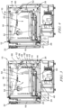
- a climate-controlled medical products storage device 10 illustratively embodied as a refrigerator is shown in Fig. 1 .
- the refrigerator 10 includes a cabinet 12 having a cabinet body 14 forming an enclosure 16 (seen in Fig. 2 ) and a door 18 which is movable between an open position shown in Fig. 2 and a closed position as shown in Fig. 1 .
- the enclosure defines a storage space 20 having a drawer 30 which defines a compartment 32.
- the door 18 includes a window 86 which allows a user to view the materials stored in the storage space 20.
- the window 86 is transparent.
- the window may be embodied as a window having variable opacity as disclosed in U.S. Pat. No. 9,574,817 .
- variable opacity can be configured based on access authority of a user - it may become transparent for approved access, remain transparent for a high access authority user, or become/remain opaque at other times hide the actual contents of the refrigerator from those contemplating diversion.
- the drawer (aka module) 30 is configured to receive and support three storage containers embodied as a storage trays 24. As will be described in further detail below, each storage tray 24 is configured to be retained within a compartment 32 within drawer 30 and inaccessible to a user under normal operating conditions.
- the cabinet 12 further includes a controller box/user interface 22 supported on the cabinet body 14.
- the controller box 22 encloses a portion of a control system.
- the control system operates similarly to the control system of U.S. Pat. No. 9,579,245, titled "Medical Products Storage Device Including Access Control,” issued February 28, 2017 .
- the actuation system 26 is configured for application to a limited number of storage trays 24 positioned in compartments 32 within drawers 30.
- the storage device 10 of the present disclosure operates a dual purpose temperature controlled storage system for general purpose storage and high value products storage.
- the device 10 may be configured with LEDs of varying colors that cause the trays 24 to be illuminated. The various colors may be illuminated continuously to permit a user to more quickly identify the type of medication or medical product stored in the particular tray 24 with a color code or illumination characteristic such as fast blink, slow blink, color sequencing etc.
- control system may be operable to perform a two-factor authentication such as detecting the presence of a radio frequency ID (RFID) badge and sensing a biometric characteristic of the user, such as a voice detection, face detection, retinal scan, or fingerprint, to confirm that the authorized user that is presented by the RFID tag is the actual user.
- RFID radio frequency ID
- the control system may be in communication with a remote authorizing entity such as a central pharmacy or particular pharmacist, such that when a user attempts to access a restricted location or tray 24, the authorizing entity is one of a dual authorization, or required to make a final authorization of the access by the user.
- This may include two-way communication between the user and an individual at the authorizing entity, or it may include the use of a camera 108 (seen in Fig. 2 ) to transmit the image of the individual attempting to access the location to the authorizing entity such that the authorizing entity may make the final determination that access is appropriate.
- the camera 108 may also provide a video feed that is recorded to provide a history of any attempts to access the space 32.
- the drawer 30 is positioned in the bottom of the enclosure 16 and configured to engage a back wall 34 of the enclosure 16.
- the drawer 30 is retained in the enclosure by security screws 36 so that the drawer 30 is fixed within the enclosure 16 and not removable without the use of tools.
- Multiple drawers 30 may be stacked upon each other to increase the number of storage trays 24 available within an enclosure 16.
- a top surface 38 of the top drawer 30 may be used to support materials being stored within the device 10. It is also understood that different height drawers 30 and corresponding different height storage trays 24 can be used or combined.
- the actuation system 26 may, like the disclosure of the '245 patent, include a detector (not shown) to detect an arm of the latch 40 to determine if the latch 40 is an expected decision.
- a load sensor (not shown) may be positioned on the surface 28 and interposed between a tray 24 and the surface 28. A single load sensor may cover the surface 28 and engage with the multiple trays 24.
- an individual load sensor may be positioned between each respective tray 24 and the surface 28.
- the load sensor(s) is/are operable to detect the presence of a tray 24, or in some embodiments, the load sensor is able to determine a weight of the tray 24 and any contents in the particular tray 24. This information is provided to the control system and used by the control system to determine if an appropriate load is present either before or after a user has accessed the particular tray 24.
- the load sensor may provide information to the control system that is used by the control system to determine that the amount of material removed from the tray 24 exceeds the amount a user has received authorization to remove. This information may then be used to identify a potential diversion of a material in the tray 24.
- the access control to the trays 24 is provided through the user interface 22 in a manner similar to that described in the '245 patent discussed above.
- the door 18 is lockable with a magnetic lock (not shown) to provide a first level of access control into the storage space 20.
- a first level of access control can be provided by the door 18 which permits a user to access materials in the enclosure 16, but not in storage trays 24.
- a user may be permitted access to a specific storage tray 24 through a user interface 22, or externally by means of ethernet or wireless based application program interface (API) commands such that the control system controls access to a specific storage tray 24 through the actuation system 26.
- API application program interface
- air within the enclosure 16 is circulated by a thermal control fan assembly 54 (shown in Fig. 3 ) to cause mixing of the air in a portion 56 of the storage space 20.
- the flow of air into the compartment 32 of the drawer 30 is limited to a flow path 58 from the portion 56 into the area of the compartment 32 for each included/attached drawer 30.
- a HEPA or HEPA/Organic reduction filter 60 is positioned at the opening of the flow path 58 and operable to treat the air flowing from the portion 56 into the flow path 58 to reduce the potential for contamination into compartment 32.
- the filter 60 may include active charcoal to remove organics from air passing through the filter 60.
- a damper 62 under the control of the control system is operable to open and close to vary the flow of air from the main portion 56 into the compartment 32 and storage space 20.
- the damper 62 is moved by a damper motor (not shown) in response to signals received from sensors (not shown) positioned in the compartment 32.
- the sensors are temperature sensors, but in other embodiments the sensors may include humidity sensors, flow sensors, or other appropriate environmental sensors that provide feedback to the control system to control the environment of the compartment 32.
- the damper 62 is movable between a fully closed position shown in Fig. 3 and a fully open position shown in Fig. 4 .
- the filter 60 and damper 62 may be omitted allowing compartment 32 to interact with the remainder of the storage space 20 is subject to the same environmental conditions as storage space 20.
- an override mechanism 68 includes a key actuated user interface 70 that is accessible when the door 18 is open as illustrated in Fig. 2 .
- a key is inserted into the user interface 70 and rotated, the rotational motion is transferred by a cylinder 72 to cause longitudinal movement of a rod 74 in the direction of an arrow 76. That longitudinal motion is transferred from rod 74 to link 78 which causes a shaft 80 to rotate about its longitudinal axis 82.
- a pair of solenoids 90, 92 are mounted to the bottom of a frame 94 of drawer 30.
- the solenoids 90, 92 include respective actuators 96, 98 which are normally extended to engage apertures in the enclosure 16 to secure the drawer 30 to the enclosure 16.
- the solenoids 90, 92 may be energized to disengage the actuators 96, 98 from the enclosure 16 to permit removal of the drawer 30 from the enclosure 16.
- a user must remove the screws 36 and actuate the solenoids 90, 92 to free the drawer 30 from the enclosure 16.
- a solenoid 40 is shown with an optional cover 110 (shown in phantom) attached to the back side 112 of the solenoid 40.
- the cover 110 is a thermoformed polymer material that electrically insulates the back arm 114 such that the back arm 114 does not electrically or magnetically engage with any metal portions of the enclosure 16 when the plunger 26 is actuated.
- the cover 110 engages the surface 118 of a coil housing 116 with an interference fit so that the back arm 114 is retained relative to the coil housing 116.
- the cover 110 is not shown in other view, but may optionally be included with any of the embodiments disclosed herein.
- the cover 110 further protects the solenoid 42 from a diversion event of being actuated by direct physical access (via diversion tool such as a bent wire) and moving of the back arm 114.
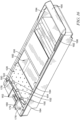
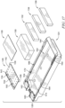
- a tray 124 is shown with additional features that may be employed to assist with avoiding diversion of various medical products 130, 132, 134, and 136 that may be stored in the tray 124 in a storage device 10.
- the tray 124 is part of a tray assembly 126 that includes a cover 128 and a cover 138.
- the covers 128 and 138 cooperate with the tray 124 to limit access to the medical products 130, 132, 134, and 136 when the tray 124 is positioned in a drawer 30.
- there are tamper resistant features of tray 124 that assist in preventing a latch 40 from being illicitly actuated to a released position by some external method, such as using a wire to reach latch 40 or solenoid arm 114.
- the spacer 140 is reinforced with three stiffeners 150, 152, 154 that extend up from the plate 142 and provide additional strength for the spacer 140 against any tampering, while also providing resistance to any attempts to deform the cover 128 to dislodge the cover 128.
- the stiffeners 150, 152 and 154 also extend slightly above spacer 140 and serve to provide a non-binding/scraping contact engagement medium between 128 and the surface 146 of the top of the compartment 32 for when tray assembly 126 is moving within compartment 32. Referring to Fig.
- the cover 128 further includes two lateral tabs 156, 158 that are positioned on opposite sides of the plate 142 and are configured to be received in recesses 170, 172 formed in the tray 124 in a snap-fit.
- the tabs 156, 158 cooperate with the two tabs 174, 176 that extend rearwardly from the plate 142 to be received with a snap-fit into recesses 178, 180 formed in the tray 124 as shown in Fig. 16 .
- the snap-fit arrangement securing the cover 128 to the tray 124 provides an additional factor for preventing the cover 128 from becoming dislodged when if a person attempts to tamper with the latch 40.
- the tray 124 is also modified as compared to the tray 24 in that the retainer 50 of tray 124 is surrounded by lateral wings 160 and 162 on the lateral sides of the retainer 50.
- the wings 160, 162 serve to prevent a wire or other illicit device from being inserted into the retainer 50 to dislodge the latch 40 from the sides by guiding the wire around the stiffener 140 of the cover 128.
- the tray 124 includes a storage space 182 that receives the medical products 130, 132, 134, and 136.
- the cover 138 is positonable on a pair of ledges 184, 186 that extend along the length of the storage space 182 to overlie the storage space 182 and prevent someone from reaching into the storage space 182 when the tray 124 is locked. It should be understood that a number of covers 138 may be positioned on the ledges 184, 186 and overlie the storage space 182. In addition, a cover may be used that is longer than the illustrative cover 138 and that overlies all of the storages space 182, even overlying the plate 142 of the cover 128.
- cover 138 may be omitted and tray 124 may be modified to include one or more hinged covers that are pivotable relative to the tray 124.
- the storage space 182 may also include dividers that are used to divide the storage space 182 into smaller sections, each with an individual cover.
- the tray 124 includes a grip 190 that extends upwardly to be approximately the same height as the spacer 140, when the spacer 140 is present.
- the grip 190 is engaged by two wings 192, 194 on the lateral sides of the grip 190 that extend rearwardly toward the retainer 50.
- the wings 192, 194 are also approximately the same height as the spacer 140 as shown in Figs. 11 and 12 .
- the height of wings 192, 194, and grip 190 reduce the clearance between the tray 124 and the surfaces of the compartment 32 to prevent the tray 124 from being manipulated in an attempt to illicitly dislodge the latch 40.
- the tray 124 further includes two side wings 196, 198 that extend downwardly from the lateral sides of the tray 124 to define a height of the tray 124 along the length of the tray 124.
- a group 200 of ribs 202 are formed from a lower surface 204 of the tray 124 at the front end 206 of the tray 124.
- An additional group 208 of ribs 210 are formed near a back end 212 of the tray 124 with the ribs 202 and 210 and the side wings 196, 198 all extending downwardly to support the tray 124 in the compartment 32.
- the ribs 202, 210 and wings 196, 198 provide additional spacing to prevent the tray 124 from being jostled or dislodged from the latch 40.
- the ribs 202 and 210 also tend to reduce the potential of an individual from guiding a wire or other device under the tray 124 to dislodge the latch 40.
- a barrier 214 is positioned near the front end 206 to provide additional support.
- the tray 124 further includes a channel 216 formed in the lower surface 204.
- the function of the channel 216 will be described with respect to optional slide stops 218 formed in the surface 28 of the drawer 230 as shown in Fig. 24 .
- the tray 124 is shown to be transparent in Figs. 24 and 25 .
- the slide stops 218 are formed by a metal working operation that extrudes the slide stops 218.
- the slide stops 218 cooperate with the channel 216 to help guide the tray 124 into and out of the compartment 32.
- the slide stops 218 help maintain the orientation of the tray 124 as it moves into and out of the compartment 32. Referring again to Fig.
- the tray 124 includes a semi-circular catch 220 that engages a respective slide stop 218 when the tray 124 is removed from a compartment 32.
- a portion 222 of the side wings 196, 198 that has a reduced height generally in the central region of the length of the tray 124. This reduction in height allows the tray 124 to be tilted when it is partially removed from the compartment 32 so that the catch 220 may be moved to a position higher than the respective slide stop 218 and fully removed from the compartment 32.
- the slide stop 218 and catch 220 tend to make the tray 124 harder to remove from the compartment 32 so that a tray 124 cannot be quickly removed and diverted.
- a tray 324 has a deeper storage space and is configured to be stored in a drawer/module that has a deeper depth.
- the tray 324 includes lateral wings 366 and 368 that extend downwardly from opposite sides of the retainer to provide a barrier to any illicit devices that may be inserted into the drawer/module in an attempt to release the tray 324 by activating a latch or actuator.
- the latch 240 is an injected molded plastic component with a front nose surface 242 that assists with displacing the latch 240 upwardly when a tray 124 is slid into the enclosure 32.
- a catch portion 242 engages the retainer 50 when the tray 124 is in the stored position shown in Fig. 11 .
- a region 248 above the catch portion 242 is specifically sized to be frangible at a particular load, as will be discussed in further detail below.
- the latch 240 pivots about an axis 246 when a link 84 or plunger 26 engages an arm 244 of the latch 240 as shown in Fig. 12 .
- the latch 240 is configured to fail if an excessive load is applied to the tray 124 in an attempt to remove the tray 124 from a compartment 32 illicitly.
- a load 250 is applied, a surface 252 of the catch portion 242 engages the surface 254 of the retainer 50 causing a tension load to be applied to the latch 240.
- the region 248 is sized to fail under a specific load, such as three-hundred (300) pounds, for example, so that the latch 240 is inoperable if the tray 124 is removed by force as shown in Fig. 22 . In this way, the tray 124 cannot be removed so that medical products 132, 134, 136, or 138 can be removed and returned without detection.
- the tray 124 is configured to withstand a load substantially larger than the load required to break the frangible region 248 of the latch 240. This provides a de facto method of determining if a storage location has been tampered with by force.
- the drawer 30 may be modified like the drawer 230 shown in Fig. 24 to include the slide stops 218. Additional modifications may include the compartment walls 232, 234 of drawer 230 which limit the movement of a particular tray 124 in a compartment so that the tray 124 cannot be moved side to side to dislodge it from the latch 40, or the latch 240.
- the drawer 230 also includes a set of flanges 236, 238 positioned on the back side of the drawer 230 between solenoids 42 so that a user cannot tamper with the solenoids 42 to move the plungers 44 to release a particular tray 124. Flanges 236 and 238 also serve as blockers preventing cross-illumination between compartments 32 when illuminated by control board 27 of Fig 7 .
- a reinforced grate structure 270 shown in Fig. 23 may be used to form the back wall 34 of the storage space 20 of the storage device 10.
- the grate structure 270 includes multiple panels 272, 274 of a reduced size so that they are less pliable.
- a lower panel 272 is positioned onto a pair of rails 276, 278 mounted to the enclosure 16.
- a pair of tabs 280, 282 are received in respective slots 284, 286 in the rails 276, 278.
- the lower panel 272 is relatively rigid.
- An upper panel 274 engages the lower panel 272 and has tabs 288, 290 that are received in slots 292, 294 of the rails 276, 278.
- a lower edge 296 of the upper panel 274 overlies a lip 298 of the lower panel 272 so that pushing on location 296 does not open a gap between 272 and 274 such that hands or a wire cannot be slipped between the panels 272, 274.
- the structure of the rails 276, 278 and the panels 272, 274 have sufficient rigidity to prevent displacement to make gaps that could be exploited to surreptitiously used to provide path for a wire or other device to release a respective latch 40 or 240.
- the upper panel 274 is further secured to the rails 276, 278 by set of fasteners 300.
- a middle filler panel (not shown) can be located between 272 and 274 that is used for each drawer 30 or 230 that is omitted from the maximum number of drawers 30 or 230 that can be included within a storage device 10.
Landscapes
- Physics & Mathematics (AREA)
- General Physics & Mathematics (AREA)
- Business, Economics & Management (AREA)
- Accounting & Taxation (AREA)
- Warehouses Or Storage Devices (AREA)
- Drawers Of Furniture (AREA)
- Cold Air Circulating Systems And Constructional Details In Refrigerators (AREA)
Claims (14)
- Dispositif de stockage (10) pour des produits médicaux, comprenantun système de contrôle,une armoire (12),un tiroir positionné dans l'armoire, le tiroir incluant une pluralité de compartiments (32), dans lequel le tiroir peut être retiré de l'armoire (1) et dans lequel le tiroir est fixé à l'armoire par un actionneur à actionnement électrique (96, 98),une pluralité de plateaux de stockage (24, 124), chaque plateau de stockage étant positionné dans un compartiment respectif de la pluralité de compartiments (32),un ensemble d'actionnement à fonctionnement électrique (26) incluant une série d'actionneurs, chacun des actionneurs de la série étant associé à un plateau de stockage respectif, chacun des actionneurs étant indépendamment actionnable pour fixer ou libérer le plateau de stockage respectif (24), auquel l'actionneur respectif est associé, relativement au compartiment (32),dans lequel chaque plateau de stockage est configuré pour être maintenu à l'intérieur de son compartiment respectif à l'intérieur du tiroir et inaccessible à un utilisateur dans des conditions de fonctionnement normales,dans lequel l'accès à un plateau de stockage spécifique de la pluralité de plateaux de stockage est contrôlé par le système de contrôle par l'intermédiaire du système d'actionnement de manière telle que, lorsque le plateau de stockage spécifique est libéré par le système d'actionnement, le plateau de stockage spécifique est permis de coulisser hors du tiroir fixé pour accéder au plateau de stockage spécifique ou pour retirer le plateau de stockage spécifique du tiroir, etun mécanisme de libération manuelle actionnable par un utilisateur pour outrepasser le système d'actionnement et libérer indépendamment tous les plateaux de stockage respectifs positionnés dans les compartiments respectifs,dans lequel le mécanisme de libération manuelle est fixé au tiroir.
- Dispositif de stockage de la revendication 1, dans lequel le mécanisme de libération manuelle inclut une interface utilisateur (70) qui est manuellement utilisable pour mouvoir le mécanisme de libération pour libérer les contenants de stockage.
- Dispositif de stockage de la revendication 2, où le mouvement de l'interface utilisateur est transféré pour entraîner un mouvement longitudinal d'une tige (74) le long d'un axe longitudinal de la tige, dans lequel le mouvement longitudinal de la tige est transféré à une liaison (78) pour entraîner un mouvement rotatif d'un arbre (80) autour de l'axe longitudinal de l'arbre et dans lequel le mouvement rotatif de l'arbre amène une liaison à entrer en prise avec une partie de l'ensemble d'actionnement pour amener les contenants de stockage à être libérés indépendamment des actionneurs.
- Dispositif de stockage de la revendication 3, dans lequel le dispositif de stockage comprend en outre un tiroir supplémentaire, chaque tiroir incluant une pluralité de compartiments de stockage, chaque tiroir comprenant en outre un mécanisme de libération manuelle distinct pour libérer seulement les plateaux de stockage ou le tiroir respectif, et dans lequel chaque mécanisme de libération manuelle est sollicité par ressort jusqu'à une position qui empêche les plateaux de stockage du tiroir d'être libérés manuellement.
- Dispositif de stockage de la revendication 4, dans lequel la libération manuelle peut être mue manuellement jusqu'à une position libérée et verrouillée dans la position libérée, et dans lequel chaque libération manuelle inclut une poignée (336) qui est normalement changeable entre une position accessible et une position inaccessible.
- Dispositif de stockage de la revendication 1, dans lequel l'ensemble d'actionnement est utilisable pour illuminer le plateau de stockage lorsque le plateau de stockage est libéré des compartiments de stockage.
- Dispositif de stockage de la revendication 1, dans lequel l'ensemble d'actionnement est utilisable pour illuminer le contenant de stockage et des informations sont transmises par une couleur ou des caractéristiques d'illumination.
- Dispositif de stockage de la revendication 1, dans lequel les contenants de stockage sont configurés pour permettre à de l'air de s'écouler à travers le contenant, sans permettre à un utilisateur d'accéder aux contenus du contenant de stockage.
- Dispositif de stockage de la revendication 8, dans lequel le contenant de stockage inclut un organe de protection (64) qui comprend un nombre d'ailettes (66), les ailettes étant espacées les unes des autres pour permettre à un écoulement d'air de s'écouler à travers l'organe de protection et dans un espace de stockage du contenant de stockage.
- Dispositif de stockage de la revendication '9, dans lequel le contenant de stockage inclut une surface de support inférieure, la surface de support inférieure (104) incluant au moins une fenêtre (102) pour permettre à de l'air de s'écouler à travers la surface de support inférieure et dans le compartiment de stockage.
- Dispositif de stockage de la revendication 1, dans lequel le système de contrôle est utilisable pour surveiller les conditions de stockage d'un article de stock stocké dans le dispositif et pour déterminer si le stock a été compromis.
- Dispositif de stockage de la revendication 11, dans lequel le dispositif de stockage inclut des capteurs pour surveiller des conditions environnementales et le système de contrôle utilise des données de capteur pour déterminer si le stock a été compromis.
- Dispositif de stockage de la revendication 12, dans lequel le système de contrôle surveille pour déterminer si un article de stock particulier a été absent d'un emplacement de stockage pour déterminer si un article de stock particulier a été compromis, et dans lequel, si un article de stock a été compromis, le système de contrôle peut changer l'état du stock stocké à un état de quarantaine, et dans lequel le système de contrôle est utilisable pour rapporter l'état de quarantaine à une autorité de supervision appropriée.
- Dispositif de stockage d'une quelconque revendication précédente, dans lequel le dispositif de stockage est utilisable pour illuminer un contenant de stockage en une couleur particulière qui correspond au type de stock stocké dans le contenant de stockage.
Priority Applications (1)
| Application Number | Priority Date | Filing Date | Title |
|---|---|---|---|
| EP25157451.3A EP4531014A3 (fr) | 2017-10-17 | 2018-10-17 | Réfrigérateur encastré avec contrôle d'accès |
Applications Claiming Priority (2)
| Application Number | Priority Date | Filing Date | Title |
|---|---|---|---|
| US201762573418P | 2017-10-17 | 2017-10-17 | |
| PCT/US2018/056309 WO2019079468A1 (fr) | 2017-10-17 | 2018-10-17 | Réfrigérateur encastré à contrôle d'accès |
Related Child Applications (2)
| Application Number | Title | Priority Date | Filing Date |
|---|---|---|---|
| EP25157451.3A Division EP4531014A3 (fr) | 2017-10-17 | 2018-10-17 | Réfrigérateur encastré avec contrôle d'accès |
| EP25157451.3A Division-Into EP4531014A3 (fr) | 2017-10-17 | 2018-10-17 | Réfrigérateur encastré avec contrôle d'accès |
Publications (3)
| Publication Number | Publication Date |
|---|---|
| EP3697260A1 EP3697260A1 (fr) | 2020-08-26 |
| EP3697260A4 EP3697260A4 (fr) | 2021-07-21 |
| EP3697260B1 true EP3697260B1 (fr) | 2025-03-26 |
Family
ID=66173879
Family Applications (2)
| Application Number | Title | Priority Date | Filing Date |
|---|---|---|---|
| EP18868381.7A Active EP3697260B1 (fr) | 2017-10-17 | 2018-10-17 | Réfrigérateur encastré à contrôle d'accès |
| EP25157451.3A Pending EP4531014A3 (fr) | 2017-10-17 | 2018-10-17 | Réfrigérateur encastré avec contrôle d'accès |
Family Applications After (1)
| Application Number | Title | Priority Date | Filing Date |
|---|---|---|---|
| EP25157451.3A Pending EP4531014A3 (fr) | 2017-10-17 | 2018-10-17 | Réfrigérateur encastré avec contrôle d'accès |
Country Status (7)
| Country | Link |
|---|---|
| US (3) | US11805898B2 (fr) |
| EP (2) | EP3697260B1 (fr) |
| AU (1) | AU2018350979B2 (fr) |
| CA (1) | CA3079391A1 (fr) |
| SA (1) | SA520411785B1 (fr) |
| SG (1) | SG11202003465QA (fr) |
| WO (1) | WO2019079468A1 (fr) |
Families Citing this family (8)
| Publication number | Priority date | Publication date | Assignee | Title |
|---|---|---|---|---|
| WO2015013625A2 (fr) | 2013-07-26 | 2015-01-29 | Helmer, Inc. | Dispositif de stockage de produits médicaux comprenant un système de contrôle d'accès |
| EP3697260B1 (fr) | 2017-10-17 | 2025-03-26 | Helmer Scientific, LLC | Réfrigérateur encastré à contrôle d'accès |
| KR102293406B1 (ko) * | 2019-12-12 | 2021-08-25 | (주)인포바이오테크 | 시약 및 의약품 보관 장치 |
| AU2021201096A1 (en) * | 2020-02-21 | 2021-09-09 | Arb Corporation Ltd | Receptacle assemblies and locking systems for such assemblies |
| CN111608538A (zh) * | 2020-04-27 | 2020-09-01 | 山东大学齐鲁医院(青岛) | 一种新型发药机上药窗口开闭门 |
| DE102020126359A1 (de) | 2020-10-08 | 2022-04-14 | Grass Gmbh | Schubladenwandelement für eine Schublade |
| AU2022202866A1 (en) * | 2021-05-03 | 2022-11-17 | Carefusion 303, Inc. | Dispensing cabinet with emergency release |
| US20250354407A1 (en) * | 2024-05-16 | 2025-11-20 | Qingdao Hiron Commercial Cold Chain Co., Ltd. | Door lock and refrigerator |
Citations (1)
| Publication number | Priority date | Publication date | Assignee | Title |
|---|---|---|---|---|
| US20040108795A1 (en) * | 2002-12-06 | 2004-06-10 | Meek Robert B. | High capacity drawer with mechanical indicator for a dispensing device |
Family Cites Families (128)
| Publication number | Priority date | Publication date | Assignee | Title |
|---|---|---|---|---|
| US2123803A (en) | 1937-07-20 | 1938-07-12 | Walter F Regenhardt | Cabinet construction |
| US2501932A (en) | 1947-03-27 | 1950-03-28 | Globe Wernicke Co | Drawer cabinet locking structure |
| DE1252546B (fr) | 1957-11-26 | |||
| US4411139A (en) | 1981-04-09 | 1983-10-25 | Amf Incorporated | Defrost control system and display panel |
| US4463348A (en) | 1981-11-23 | 1984-07-31 | General Electric Company | Refrigerator door usage monitor and display system |
| US4441329A (en) | 1982-07-06 | 1984-04-10 | Dawley Robert E | Temperature control system |
| US4566285A (en) | 1984-01-26 | 1986-01-28 | Whirlpool Corporation | Refrigerator door ajar alarm with variable delay |
| US4560088A (en) | 1984-05-11 | 1985-12-24 | Tan Larry K | Vending machine with dispensing operating system movable in X-Y coordinate axes |
| US4616890A (en) * | 1985-01-14 | 1986-10-14 | Romick Jerome M | Medication carts and cassettes |
| US5025950A (en) | 1990-01-16 | 1991-06-25 | Hobart Corporation | Apparatus for storing and dispensing frozen comestibles |
| US5314244A (en) * | 1990-05-10 | 1994-05-24 | Herman Miller, Inc. | Pharmaceutical cabinet locking arrangement |
| US5139321A (en) * | 1991-01-18 | 1992-08-18 | Artromick International, Inc. | Multiple-bin tray assembly for a medical dispensing cassette |
| US5262758A (en) | 1991-09-19 | 1993-11-16 | Nam Young K | System and method for monitoring temperature |
| GB2277043B (en) | 1993-04-13 | 1996-10-30 | David John Fletcher | Orbital shaking attachment |
| US5905653A (en) | 1994-07-14 | 1999-05-18 | Omnicell Technologies, Inc. | Methods and devices for dispensing pharmaceutical and medical supply items |
| US5745366A (en) * | 1994-07-14 | 1998-04-28 | Omnicell Technologies, Inc. | Pharmaceutical dispensing device and methods |
| US5661978A (en) * | 1994-12-09 | 1997-09-02 | Pyxis Corporation | Medical dispensing drawer and thermoelectric device for cooling the contents therein |
| US5735587A (en) | 1995-02-06 | 1998-04-07 | Liconic Ag | Climatic cabinet, turntable and use of the turntable |
| US5596878A (en) | 1995-06-26 | 1997-01-28 | Thermo King Corporation | Methods and apparatus for operating a refrigeration unit |
| US5716114A (en) * | 1996-06-07 | 1998-02-10 | Pyxis Corporation | Jerk-resistant drawer operating system |
| US5623836A (en) | 1995-09-14 | 1997-04-29 | Paragon Electric Company, Inc. | Electronic refrigeration control system |
| JP2885148B2 (ja) | 1995-09-29 | 1999-04-19 | ダイキン工業株式会社 | コンテナ用冷凍装置 |
| US6129428A (en) | 1996-08-05 | 2000-10-10 | Kendro Laboratory Products Gmbh | Storage device for objects, storage station and air-conditioned cabinet |
| US6021392A (en) | 1996-12-09 | 2000-02-01 | Pyxis Corporation | System and method for drug management |
| US6988248B1 (en) | 1997-06-30 | 2006-01-17 | Sun Microsystems, Inc. | Animated indicators that reflect function activity or state of objects data or processes |
| US6116067A (en) | 1997-11-12 | 2000-09-12 | Fort Lock Corporation | Electronically controlled lock system for tool containers |
| US6011999A (en) * | 1997-12-05 | 2000-01-04 | Omnicell Technologies, Inc. | Apparatus for controlled dispensing of pharmaceutical and medical supplies |
| US6116461A (en) * | 1998-05-29 | 2000-09-12 | Pyxis Corporation | Method and apparatus for the dispensing of drugs |
| US6788997B1 (en) | 1998-06-01 | 2004-09-07 | Medselect, Inc. | Medical cabinet with adjustable drawers |
| US6306658B1 (en) | 1998-08-13 | 2001-10-23 | Symyx Technologies | Parallel reactor with internal sensing |
| US6274374B1 (en) | 1998-09-19 | 2001-08-14 | Thomas W. Astle | Combination stacker/incubator system for bioassay trays |
| JP3799876B2 (ja) | 1999-06-23 | 2006-07-19 | 松下電器産業株式会社 | インキュベータ |
| US6151536A (en) | 1998-09-28 | 2000-11-21 | Omnicell.Com | Dispensing system and methods |
| DE19936572B4 (de) | 1999-08-03 | 2005-05-19 | Carl Zeiss Jena Gmbh | Klimaschrank |
| US6464142B1 (en) | 1999-10-29 | 2002-10-15 | Si/Baker, Inc. | Automated will call system |
| US6401466B1 (en) | 2000-03-14 | 2002-06-11 | Donald Olsen | Door monitor apparatus for interrupting and restoring walk-in refrigeration system operation and alarm monitoring system therefor |
| US7262698B1 (en) | 2000-05-05 | 2007-08-28 | Automed Technologies, Inc. | Medical item storage cabinet and method |
| US6658322B1 (en) | 2000-05-05 | 2003-12-02 | Medselect Inc. | System and method for tracking medical items and supplies |
| DE10024581A1 (de) | 2000-05-19 | 2001-11-29 | Kendro Lab Prod Gmbh | Klimaschrank |
| US6917853B2 (en) | 2000-05-23 | 2005-07-12 | Munroe Chirnomas | Method and apparatus for controlling rented or leased or loaned equipment |
| DE60144402D1 (de) | 2000-10-20 | 2011-05-19 | Promega Corp | Hochfrequenzidenfikationsverfahren und System zum Verteilen von Produkten |
| US20020183882A1 (en) | 2000-10-20 | 2002-12-05 | Michael Dearing | RF point of sale and delivery method and system using communication with remote computer and having features to read a large number of RF tags |
| US6595430B1 (en) | 2000-10-26 | 2003-07-22 | Honeywell International Inc. | Graphical user interface system for a thermal comfort controller |
| DE10057242A1 (de) | 2000-11-18 | 2002-05-29 | Bosch Gmbh Robert | Kupplung für eine Steer-by-Wire-Lenkanlage |
| DE10058564A1 (de) | 2000-11-24 | 2002-06-06 | Kendro Lab Prod Gmbh | Objektlagerstation und Klimaschrank |
| WO2002059251A2 (fr) | 2001-01-26 | 2002-08-01 | Liconic Ag | Armoire de stockage climatisee |
| US6532399B2 (en) | 2001-06-05 | 2003-03-11 | Baxter International Inc. | Dispensing method using indirect coupling |
| US6707381B1 (en) | 2001-06-26 | 2004-03-16 | Key-Trak, Inc. | Object tracking method and system with object identification and verification |
| US7158030B2 (en) | 2001-09-19 | 2007-01-02 | Avante International Technology | Medical assistance and tracking system and method employing smart tags |
| US9460413B2 (en) | 2001-10-10 | 2016-10-04 | Thermo Fisher Scientific Inc. | System and method for product tracking and product temperature profiling |
| FR2825638B1 (fr) | 2001-10-18 | 2003-09-12 | Biolog | Procede de determination et de suivi du vieillissement des poches de sang dans les etablissements de transfusion sanguine et les etablissements de soins |
| US20030105555A1 (en) | 2001-11-30 | 2003-06-05 | Lunak Richard R. | Method of issuing medical supplies and dispensing and administering medications through a hand-held device and a device and system for doing the same |
| US8068023B2 (en) | 2001-12-28 | 2011-11-29 | Dulin Jacques M | System for maintaining security of evidence throughout chain of custody |
| KR100998145B1 (ko) | 2002-02-20 | 2010-12-02 | 산요덴키가부시키가이샤 | 약제 공급 장치 |
| US6935560B2 (en) | 2002-02-26 | 2005-08-30 | Safety Syringes, Inc. | Systems and methods for tracking pharmaceuticals within a facility |
| US6691058B2 (en) | 2002-04-29 | 2004-02-10 | Hewlett-Packard Development Company, L.P. | Determination of pharmaceutical expiration date |
| WO2004014189A1 (fr) * | 2002-08-07 | 2004-02-19 | Supplypro, Inc. | Appareil de securisation de contenus dans des tiroirs |
| US6926377B2 (en) * | 2002-08-08 | 2005-08-09 | Compx International Inc. | Drawer slide latch and release mechanism |
| US20040050750A1 (en) * | 2002-09-18 | 2004-03-18 | Hannan Robin E. | Medication cart drawer liner and method for using same to reduce nosocomial infections |
| US20040044326A1 (en) | 2002-08-30 | 2004-03-04 | Kranz Lewis M. | Method for tracking bags of blood and blood products |
| US7623032B2 (en) * | 2002-12-05 | 2009-11-24 | Key Control Holding, Inc. | Object controlled access and inventory system |
| US6775591B1 (en) | 2003-01-24 | 2004-08-10 | S&S X-Ray Products, Inc. | Portable medication dispensing unit |
| CA2419647A1 (fr) | 2003-02-21 | 2004-08-21 | Jean-Pierre Gingras | Systeme de commande et de surveillance de chambre froide |
| GB2401143B (en) * | 2003-04-07 | 2006-06-14 | Cash Bases Ltd | Cash drawers |
| ES2289480T3 (es) | 2004-02-09 | 2008-02-01 | Angelantoni Industrie Spa | Aparato para recibir, almacenar y suministrar bolsas de sangre. |
| WO2005109119A2 (fr) | 2004-04-24 | 2005-11-17 | Inrange Systems, Inc. | Systeme de gestion et d'observation de medication integre, non sequentiel et a distance |
| US7348884B2 (en) | 2004-07-29 | 2008-03-25 | Omnicell, Inc. | RFID cabinet |
| US7570786B2 (en) | 2004-08-30 | 2009-08-04 | Antoun Ateya | Automatic digital object counting and verification system and associated method |
| DE202005021564U1 (de) | 2004-09-21 | 2008-10-02 | Keba Ag | Aufbewahrungsautomat für Gegenstände |
| DK1806967T3 (da) | 2004-09-29 | 2008-08-18 | Angelantoni Ind Spa | Apparat og fremgangsmåde til modtagelse, opbevaring og distribution af blodposer |
| US7638100B2 (en) | 2004-11-02 | 2009-12-29 | Helmer, Inc. | Platelet incubator |
| US7617690B2 (en) | 2004-11-02 | 2009-11-17 | Helmer, Inc. | Blood products freezer with event log |
| US7178729B2 (en) | 2005-02-25 | 2007-02-20 | Cisco Technology, Inc. | Methods and devices for providing alerts for spoilage and hazardous combinations |
| WO2007064816A2 (fr) | 2005-12-02 | 2007-06-07 | Asd Specialty Healthcare, Inc. D/B/A Amerisourcebergen Specialty Group | Systeme et procede destines a la gestion et au suivi pharmaceutiques |
| US7630791B2 (en) | 2005-12-09 | 2009-12-08 | CareFusion 303 Inc. | System and method for storing items and tracking item usage |
| US7775056B2 (en) | 2006-01-18 | 2010-08-17 | Merck Sharp & Dohme Corp. | Intelligent refrigerator for storing pharmaceutical product containers |
| US20070192315A1 (en) | 2006-02-13 | 2007-08-16 | Drzaic Paul S | Database search with RFID |
| US8063735B2 (en) | 2006-03-29 | 2011-11-22 | SIS X-Ray Products, Inc. | Remotely actuated refrigerator lock with thermal spoilage protection |
| US7668620B2 (en) | 2006-04-12 | 2010-02-23 | S&S X-Ray Products, Inc. | Wall mounted medications cabinet |
| US8036773B2 (en) | 2006-05-10 | 2011-10-11 | Mckesson Automation Inc. | System, method and corresponding apparatus for storing, retrieving and delivering unit dose blisters |
| US8405508B2 (en) | 2006-08-09 | 2013-03-26 | Emd Millipore Corporation | Use of gamma hardened RFID tags in pharmaceutical devices |
| US20080270178A1 (en) | 2007-04-30 | 2008-10-30 | Mckesson Specialty Distribution Llc | Inventory Management System For A Medical Service Provider |
| US8065035B2 (en) | 2007-05-02 | 2011-11-22 | Carefusion 303, Inc. | Automated medication handling system |
| US8914148B2 (en) | 2007-11-26 | 2014-12-16 | Micro Datastat, Ltd. | Pharmacy medication verification system |
| US8006903B2 (en) | 2007-12-28 | 2011-08-30 | Mckesson Automation, Inc. | Proximity-based inventory management system using RFID tags to aid in dispensing and restocking inventory |
| US8376228B2 (en) | 2008-02-04 | 2013-02-19 | Target Brands, Inc. | Product identification and tracking |
| US7992746B2 (en) | 2008-02-11 | 2011-08-09 | Carefusion 303, Inc. | Method and apparatus for removing, inserting and securing receptacles in a receptacle tray |
| US7719420B2 (en) | 2008-02-14 | 2010-05-18 | Mckesson Automation Inc. | Lock status notification and next case medication method, apparatus and corresponding medication storage device |
| US8109527B2 (en) * | 2008-02-21 | 2012-02-07 | Rubbermaid, Inc. | Medical cart and keyboard tray |
| GB2461070A (en) * | 2008-06-19 | 2009-12-23 | Shafir Production Systems Ltd | Cabinet for handling distributable items comprising drawer access and control system and lockable bins |
| CA2638437C (fr) | 2008-07-31 | 2015-08-18 | Aumat Co. Inc. | Distributeur de medicament |
| GB2463054A (en) | 2008-08-30 | 2010-03-03 | Adavanced Telecare Solutions L | Device for monitoring the removal of items placed in compartments of a blister package using ambient light |
| US8731958B2 (en) | 2008-10-31 | 2014-05-20 | Advantage Pharmacy Services Llc | Administering of medication |
| US8744620B2 (en) | 2008-10-31 | 2014-06-03 | Medminder Systems, Inc. | Interactive medication dispensing system with locking compartments |
| US8103379B2 (en) | 2009-01-09 | 2012-01-24 | Automed Technologies, Inc. | Medication cabinetry |
| US8744621B2 (en) | 2009-01-09 | 2014-06-03 | Automed Technologies, Inc. | Medical cabinet access belt optimization system |
| US20110202170A1 (en) | 2010-02-09 | 2011-08-18 | Dawes Dennis K | Access and inventory control for climate controlled storage |
| GB2478794A (en) * | 2010-03-19 | 2011-09-21 | Supply Point Systems Ltd | Storage system for supplying articles |
| CA2701396A1 (fr) | 2010-04-22 | 2011-10-22 | Leon Saltsov | Unite de distribution de medicaments et de controle |
| US20120130534A1 (en) | 2010-11-19 | 2012-05-24 | Scott Wurm | Access controlled medication storage and inventory control apparatus |
| EP2645903A4 (fr) * | 2010-12-03 | 2018-01-24 | TouchPoint Medical, Inc. | Dispositif de stockage comportant un mécanisme de verrouillage |
| US8473097B2 (en) | 2010-12-15 | 2013-06-25 | S & S X-Ray Products, Inc | Pass-through wall-mounted medications cabinet with UV sterilization |
| TWI433040B (zh) | 2010-12-28 | 2014-04-01 | 艾迪訊科技股份有限公司 | Application of radio frequency identification technology in intelligent lockers and management methods |
| US9131774B2 (en) * | 2011-01-24 | 2015-09-15 | Carefusion 303, Inc. | Self-guiding insertion and bias mechanism |
| US8376478B2 (en) * | 2011-01-24 | 2013-02-19 | Carefusion 303, Inc. | Tamper-evident fastener |
| US8983653B2 (en) * | 2011-07-15 | 2015-03-17 | Advantage Pharmacy Services Llc | Electromechanical latch and ejector |
| US9910965B2 (en) * | 2011-09-16 | 2018-03-06 | Aesynt Incorporated | Systems, methods and computer program product for monitoring interactions with a medication storage device |
| US9078520B2 (en) | 2011-11-08 | 2015-07-14 | S&S X-Ray, Products Inc | Locking bin drawer with slide-out trays for medications cabinet |
| US9733647B2 (en) * | 2011-12-05 | 2017-08-15 | The United States Postal Service | System and method of control of electronic parcel lockers |
| CA2800540A1 (fr) | 2012-01-05 | 2013-07-05 | Advantage Pharmacy Services Llc | Tiroir a medicaments et bande de conditionnement de medicaments |
| AU2013235404B2 (en) * | 2012-03-20 | 2017-08-10 | Touchpoint Medical, Inc. | Medication dispensing apparatus having drawer assembly with discrete compartments |
| US8972051B2 (en) | 2012-05-29 | 2015-03-03 | Carefusion 303, Inc. | Multi-compartment step-drawer |
| US9157261B2 (en) * | 2012-05-29 | 2015-10-13 | Carefusion 303, Inc. | Multifunction latch assembly |
| MX370505B (es) * | 2013-03-04 | 2019-12-13 | Scott Clark L P | Mecanismo de bloqueo del cajón y carro móvil para el suministro de medicina que comprende el mismo. |
| US9349238B2 (en) | 2013-03-13 | 2016-05-24 | Pantry Retail, Inc. | Vending kit and method |
| EP2972767B1 (fr) | 2013-03-15 | 2022-09-28 | TouchPoint Medical, Inc. | Appareil de stockage et de distribution de médicaments |
| US9081887B2 (en) | 2013-03-15 | 2015-07-14 | Intermetro Industries Corporation | Medication storage and dispensing apparatus having linear drawer assembly including discrete storage modules |
| US9574817B2 (en) | 2013-03-15 | 2017-02-21 | Helmer, Inc. | Medical products storage device with viewing window having variable opacity |
| WO2014145074A1 (fr) | 2013-03-15 | 2014-09-18 | Makefield Llc | Déshydratants fonctionnels |
| US20170284732A1 (en) | 2013-04-23 | 2017-10-05 | Minibar North America, Inc. | Controlled inventory refrigerated dispensing system |
| WO2015013625A2 (fr) | 2013-07-26 | 2015-01-29 | Helmer, Inc. | Dispositif de stockage de produits médicaux comprenant un système de contrôle d'accès |
| US9224124B2 (en) | 2013-10-29 | 2015-12-29 | Mobile Aspects, Inc. | Item storage and tracking cabinet and arrangement |
| US10383438B2 (en) * | 2015-03-16 | 2019-08-20 | Cubex Llc | Devices for controlled dispensing |
| US10045617B2 (en) * | 2015-05-26 | 2018-08-14 | Midwest Products and Engineering, Inc. | Pharmaceutical management storage cabinet |
| ES2904497T3 (es) * | 2015-11-13 | 2022-04-05 | Humanscale Corp | Una estación de tecnología médica y método de uso |
| US10045899B2 (en) * | 2016-07-06 | 2018-08-14 | Capsa Solutions Llc | Modular and fully traceable delivery system |
| EP3697260B1 (fr) | 2017-10-17 | 2025-03-26 | Helmer Scientific, LLC | Réfrigérateur encastré à contrôle d'accès |
| US10663218B2 (en) * | 2017-11-17 | 2020-05-26 | Omnicell, Inc. | Dispensing system with temperature controlled drawers |
-
2018
- 2018-10-17 EP EP18868381.7A patent/EP3697260B1/fr active Active
- 2018-10-17 AU AU2018350979A patent/AU2018350979B2/en active Active
- 2018-10-17 WO PCT/US2018/056309 patent/WO2019079468A1/fr not_active Ceased
- 2018-10-17 SG SG11202003465QA patent/SG11202003465QA/en unknown
- 2018-10-17 US US16/756,634 patent/US11805898B2/en active Active
- 2018-10-17 EP EP25157451.3A patent/EP4531014A3/fr active Pending
- 2018-10-17 CA CA3079391A patent/CA3079391A1/fr active Pending
-
2020
- 2020-04-16 SA SA520411785A patent/SA520411785B1/ar unknown
-
2023
- 2023-09-13 US US18/466,607 patent/US12349789B2/en active Active
-
2025
- 2025-06-04 US US19/228,176 patent/US20250295230A1/en active Pending
Patent Citations (1)
| Publication number | Priority date | Publication date | Assignee | Title |
|---|---|---|---|---|
| US20040108795A1 (en) * | 2002-12-06 | 2004-06-10 | Meek Robert B. | High capacity drawer with mechanical indicator for a dispensing device |
Also Published As
| Publication number | Publication date |
|---|---|
| SA520411785B1 (ar) | 2023-12-05 |
| EP4531014A2 (fr) | 2025-04-02 |
| WO2019079468A1 (fr) | 2019-04-25 |
| US20250295230A1 (en) | 2025-09-25 |
| US20200268149A1 (en) | 2020-08-27 |
| SG11202003465QA (en) | 2020-05-28 |
| AU2018350979B2 (en) | 2023-12-21 |
| EP4531014A3 (fr) | 2025-06-25 |
| US11805898B2 (en) | 2023-11-07 |
| US20240000226A1 (en) | 2024-01-04 |
| CA3079391A1 (fr) | 2019-04-25 |
| US12349789B2 (en) | 2025-07-08 |
| EP3697260A1 (fr) | 2020-08-26 |
| EP3697260A4 (fr) | 2021-07-21 |
| AU2018350979A1 (en) | 2020-05-07 |
Similar Documents
| Publication | Publication Date | Title |
|---|---|---|
| US12349789B2 (en) | Undercounter refrigerator with access control | |
| US9289061B2 (en) | Secure file cabinet | |
| US7728711B2 (en) | Remotely or locally actuated refrigerator lock with temperature and humidity detection | |
| US8196939B2 (en) | Medical cart and drawer assembly and lock | |
| US9322207B2 (en) | Door assembly for storage and dispensing unit | |
| CA2257797C (fr) | Systeme d'ouverture commandee de tiroirs avec impossibilite d'une brusque ouverture complete | |
| CA3016660C (fr) | Dispositif et procede de distribution regulee | |
| US20090231132A1 (en) | Remotely Actuated Refrigerator Lock with Thermal Spoilage Protection | |
| EP3369079B1 (fr) | Ensemble boîtier de détecteur | |
| CN107532434B (zh) | 具有指示器的闩锁以及闩锁系统 | |
| CN102862774A (zh) | 物品自动管理存取设备 | |
| US8528993B2 (en) | Sealing structure for sealing multiple sections and a drawer of a medical emergency cart | |
| US20080231154A1 (en) | Locking Systems | |
| US20070227204A1 (en) | Remotely actuated refrigerator lock | |
| EP2609268B1 (fr) | Système de verrouillage | |
| CZ369192A3 (en) | Set of exchangeable cassettes | |
| WO2016151180A1 (fr) | Procédé et système servant à contrôler le stockage des emballages ou ampoules de médicaments, et un dispositif de stockage pour emballages de médicaments | |
| GB2587648A (en) | Security apparatus and assembly for an ATM |
Legal Events
| Date | Code | Title | Description |
|---|---|---|---|
| STAA | Information on the status of an ep patent application or granted ep patent |
Free format text: STATUS: THE INTERNATIONAL PUBLICATION HAS BEEN MADE |
|
| PUAI | Public reference made under article 153(3) epc to a published international application that has entered the european phase |
Free format text: ORIGINAL CODE: 0009012 |
|
| STAA | Information on the status of an ep patent application or granted ep patent |
Free format text: STATUS: REQUEST FOR EXAMINATION WAS MADE |
|
| 17P | Request for examination filed |
Effective date: 20200430 |
|
| AK | Designated contracting states |
Kind code of ref document: A1 Designated state(s): AL AT BE BG CH CY CZ DE DK EE ES FI FR GB GR HR HU IE IS IT LI LT LU LV MC MK MT NL NO PL PT RO RS SE SI SK SM TR |
|
| AX | Request for extension of the european patent |
Extension state: BA ME |
|
| DAV | Request for validation of the european patent (deleted) | ||
| DAX | Request for extension of the european patent (deleted) | ||
| REG | Reference to a national code |
Ref country code: DE Ref legal event code: R079 Free format text: PREVIOUS MAIN CLASS: A47B0067020000 Ipc: G07F0017000000 Ref document number: 602018080565 Country of ref document: DE |
|
| A4 | Supplementary search report drawn up and despatched |
Effective date: 20210617 |
|
| RIC1 | Information provided on ipc code assigned before grant |
Ipc: G07F 17/00 20060101AFI20210611BHEP Ipc: A47B 88/40 20170101ALI20210611BHEP Ipc: A47B 67/02 20060101ALI20210611BHEP Ipc: A47B 67/04 20060101ALI20210611BHEP Ipc: A47B 88/90 20170101ALI20210611BHEP Ipc: G07F 11/62 20060101ALI20210611BHEP Ipc: E05B 47/00 20060101ALI20210611BHEP Ipc: E05B 65/462 20170101ALI20210611BHEP Ipc: E05B 17/00 20060101ALI20210611BHEP Ipc: E05B 47/02 20060101ALI20210611BHEP Ipc: G07F 9/10 20060101ALI20210611BHEP Ipc: G07F 9/02 20060101ALI20210611BHEP Ipc: G07G 1/00 20060101ALI20210611BHEP |
|
| RAP1 | Party data changed (applicant data changed or rights of an application transferred) |
Owner name: HELMER SCIENTIFIC, LLC |
|
| P01 | Opt-out of the competence of the unified patent court (upc) registered |
Effective date: 20230605 |
|
| STAA | Information on the status of an ep patent application or granted ep patent |
Free format text: STATUS: EXAMINATION IS IN PROGRESS |
|
| 17Q | First examination report despatched |
Effective date: 20230929 |
|
| GRAP | Despatch of communication of intention to grant a patent |
Free format text: ORIGINAL CODE: EPIDOSNIGR1 |
|
| STAA | Information on the status of an ep patent application or granted ep patent |
Free format text: STATUS: GRANT OF PATENT IS INTENDED |
|
| INTG | Intention to grant announced |
Effective date: 20241111 |
|
| GRAS | Grant fee paid |
Free format text: ORIGINAL CODE: EPIDOSNIGR3 |
|
| GRAA | (expected) grant |
Free format text: ORIGINAL CODE: 0009210 |
|
| STAA | Information on the status of an ep patent application or granted ep patent |
Free format text: STATUS: THE PATENT HAS BEEN GRANTED |
|
| AK | Designated contracting states |
Kind code of ref document: B1 Designated state(s): AL AT BE BG CH CY CZ DE DK EE ES FI FR GB GR HR HU IE IS IT LI LT LU LV MC MK MT NL NO PL PT RO RS SE SI SK SM TR |
|
| REG | Reference to a national code |
Ref country code: GB Ref legal event code: FG4D |
|
| REG | Reference to a national code |
Ref country code: CH Ref legal event code: EP |
|
| REG | Reference to a national code |
Ref country code: DE Ref legal event code: R096 Ref document number: 602018080565 Country of ref document: DE |
|
| REG | Reference to a national code |
Ref country code: IE Ref legal event code: FG4D |
|
| PG25 | Lapsed in a contracting state [announced via postgrant information from national office to epo] |
Ref country code: RS Free format text: LAPSE BECAUSE OF FAILURE TO SUBMIT A TRANSLATION OF THE DESCRIPTION OR TO PAY THE FEE WITHIN THE PRESCRIBED TIME-LIMIT Effective date: 20250626 |
|
| PG25 | Lapsed in a contracting state [announced via postgrant information from national office to epo] |
Ref country code: FI Free format text: LAPSE BECAUSE OF FAILURE TO SUBMIT A TRANSLATION OF THE DESCRIPTION OR TO PAY THE FEE WITHIN THE PRESCRIBED TIME-LIMIT Effective date: 20250326 |
|
| REG | Reference to a national code |
Ref country code: LT Ref legal event code: MG9D |
|
| PG25 | Lapsed in a contracting state [announced via postgrant information from national office to epo] |
Ref country code: NO Free format text: LAPSE BECAUSE OF FAILURE TO SUBMIT A TRANSLATION OF THE DESCRIPTION OR TO PAY THE FEE WITHIN THE PRESCRIBED TIME-LIMIT Effective date: 20250626 |
|
| PG25 | Lapsed in a contracting state [announced via postgrant information from national office to epo] |
Ref country code: HR Free format text: LAPSE BECAUSE OF FAILURE TO SUBMIT A TRANSLATION OF THE DESCRIPTION OR TO PAY THE FEE WITHIN THE PRESCRIBED TIME-LIMIT Effective date: 20250326 |
|
| PG25 | Lapsed in a contracting state [announced via postgrant information from national office to epo] |
Ref country code: LV Free format text: LAPSE BECAUSE OF FAILURE TO SUBMIT A TRANSLATION OF THE DESCRIPTION OR TO PAY THE FEE WITHIN THE PRESCRIBED TIME-LIMIT Effective date: 20250326 |
|
| PG25 | Lapsed in a contracting state [announced via postgrant information from national office to epo] |
Ref country code: BG Free format text: LAPSE BECAUSE OF FAILURE TO SUBMIT A TRANSLATION OF THE DESCRIPTION OR TO PAY THE FEE WITHIN THE PRESCRIBED TIME-LIMIT Effective date: 20250326 Ref country code: GR Free format text: LAPSE BECAUSE OF FAILURE TO SUBMIT A TRANSLATION OF THE DESCRIPTION OR TO PAY THE FEE WITHIN THE PRESCRIBED TIME-LIMIT Effective date: 20250627 |
|
| REG | Reference to a national code |
Ref country code: NL Ref legal event code: MP Effective date: 20250326 |
|
| PG25 | Lapsed in a contracting state [announced via postgrant information from national office to epo] |
Ref country code: NL Free format text: LAPSE BECAUSE OF FAILURE TO SUBMIT A TRANSLATION OF THE DESCRIPTION OR TO PAY THE FEE WITHIN THE PRESCRIBED TIME-LIMIT Effective date: 20250326 |
|
| PG25 | Lapsed in a contracting state [announced via postgrant information from national office to epo] |
Ref country code: SE Free format text: LAPSE BECAUSE OF FAILURE TO SUBMIT A TRANSLATION OF THE DESCRIPTION OR TO PAY THE FEE WITHIN THE PRESCRIBED TIME-LIMIT Effective date: 20250326 |
|
| REG | Reference to a national code |
Ref country code: AT Ref legal event code: MK05 Ref document number: 1779746 Country of ref document: AT Kind code of ref document: T Effective date: 20250326 |
|
| PG25 | Lapsed in a contracting state [announced via postgrant information from national office to epo] |
Ref country code: SM Free format text: LAPSE BECAUSE OF FAILURE TO SUBMIT A TRANSLATION OF THE DESCRIPTION OR TO PAY THE FEE WITHIN THE PRESCRIBED TIME-LIMIT Effective date: 20250326 |
|
| PG25 | Lapsed in a contracting state [announced via postgrant information from national office to epo] |
Ref country code: ES Free format text: LAPSE BECAUSE OF FAILURE TO SUBMIT A TRANSLATION OF THE DESCRIPTION OR TO PAY THE FEE WITHIN THE PRESCRIBED TIME-LIMIT Effective date: 20250326 Ref country code: PT Free format text: LAPSE BECAUSE OF FAILURE TO SUBMIT A TRANSLATION OF THE DESCRIPTION OR TO PAY THE FEE WITHIN THE PRESCRIBED TIME-LIMIT Effective date: 20250728 |
|
| PG25 | Lapsed in a contracting state [announced via postgrant information from national office to epo] |
Ref country code: IT Free format text: LAPSE BECAUSE OF FAILURE TO SUBMIT A TRANSLATION OF THE DESCRIPTION OR TO PAY THE FEE WITHIN THE PRESCRIBED TIME-LIMIT Effective date: 20250326 Ref country code: PL Free format text: LAPSE BECAUSE OF FAILURE TO SUBMIT A TRANSLATION OF THE DESCRIPTION OR TO PAY THE FEE WITHIN THE PRESCRIBED TIME-LIMIT Effective date: 20250326 |
|
| PGFP | Annual fee paid to national office [announced via postgrant information from national office to epo] |
Ref country code: GB Payment date: 20250923 Year of fee payment: 8 |
|
| PG25 | Lapsed in a contracting state [announced via postgrant information from national office to epo] |
Ref country code: AT Free format text: LAPSE BECAUSE OF FAILURE TO SUBMIT A TRANSLATION OF THE DESCRIPTION OR TO PAY THE FEE WITHIN THE PRESCRIBED TIME-LIMIT Effective date: 20250326 |
|
| PGFP | Annual fee paid to national office [announced via postgrant information from national office to epo] |
Ref country code: FR Payment date: 20250923 Year of fee payment: 8 |
|
| PG25 | Lapsed in a contracting state [announced via postgrant information from national office to epo] |
Ref country code: EE Free format text: LAPSE BECAUSE OF FAILURE TO SUBMIT A TRANSLATION OF THE DESCRIPTION OR TO PAY THE FEE WITHIN THE PRESCRIBED TIME-LIMIT Effective date: 20250326 |
|
| PG25 | Lapsed in a contracting state [announced via postgrant information from national office to epo] |
Ref country code: RO Free format text: LAPSE BECAUSE OF FAILURE TO SUBMIT A TRANSLATION OF THE DESCRIPTION OR TO PAY THE FEE WITHIN THE PRESCRIBED TIME-LIMIT Effective date: 20250326 |
|
| PG25 | Lapsed in a contracting state [announced via postgrant information from national office to epo] |
Ref country code: SK Free format text: LAPSE BECAUSE OF FAILURE TO SUBMIT A TRANSLATION OF THE DESCRIPTION OR TO PAY THE FEE WITHIN THE PRESCRIBED TIME-LIMIT Effective date: 20250326 |
|
| PG25 | Lapsed in a contracting state [announced via postgrant information from national office to epo] |
Ref country code: IS Free format text: LAPSE BECAUSE OF FAILURE TO SUBMIT A TRANSLATION OF THE DESCRIPTION OR TO PAY THE FEE WITHIN THE PRESCRIBED TIME-LIMIT Effective date: 20250726 |
|
| REG | Reference to a national code |
Ref country code: DE Ref legal event code: R097 Ref document number: 602018080565 Country of ref document: DE |
|
| PGFP | Annual fee paid to national office [announced via postgrant information from national office to epo] |
Ref country code: DE Payment date: 20250923 Year of fee payment: 8 |
|
| PG25 | Lapsed in a contracting state [announced via postgrant information from national office to epo] |
Ref country code: DK Free format text: LAPSE BECAUSE OF FAILURE TO SUBMIT A TRANSLATION OF THE DESCRIPTION OR TO PAY THE FEE WITHIN THE PRESCRIBED TIME-LIMIT Effective date: 20250326 |
|
| PG25 | Lapsed in a contracting state [announced via postgrant information from national office to epo] |
Ref country code: CZ Free format text: LAPSE BECAUSE OF FAILURE TO SUBMIT A TRANSLATION OF THE DESCRIPTION OR TO PAY THE FEE WITHIN THE PRESCRIBED TIME-LIMIT Effective date: 20250326 |
|
| PLBE | No opposition filed within time limit |
Free format text: ORIGINAL CODE: 0009261 |
|
| STAA | Information on the status of an ep patent application or granted ep patent |
Free format text: STATUS: NO OPPOSITION FILED WITHIN TIME LIMIT |
|
| REG | Reference to a national code |
Ref country code: CH Ref legal event code: L10 Free format text: ST27 STATUS EVENT CODE: U-0-0-L10-L00 (AS PROVIDED BY THE NATIONAL OFFICE) Effective date: 20260211 |
|
| 26N | No opposition filed |
Effective date: 20260105 |