EP3697284B1 - Procédé pour la fabrication d'un tuyau d'introduction d'un endoscope et endoscope présentant un tuyau d'introduction - Google Patents
Procédé pour la fabrication d'un tuyau d'introduction d'un endoscope et endoscope présentant un tuyau d'introduction Download PDFInfo
- Publication number
- EP3697284B1 EP3697284B1 EP18797086.8A EP18797086A EP3697284B1 EP 3697284 B1 EP3697284 B1 EP 3697284B1 EP 18797086 A EP18797086 A EP 18797086A EP 3697284 B1 EP3697284 B1 EP 3697284B1
- Authority
- EP
- European Patent Office
- Prior art keywords
- section
- tube element
- insertion tube
- cut
- tube
- Prior art date
- Legal status (The legal status is an assumption and is not a legal conclusion. Google has not performed a legal analysis and makes no representation as to the accuracy of the status listed.)
- Active
Links
Images


Classifications
-
- A—HUMAN NECESSITIES
- A61—MEDICAL OR VETERINARY SCIENCE; HYGIENE
- A61B—DIAGNOSIS; SURGERY; IDENTIFICATION
- A61B1/00—Instruments for performing medical examinations of the interior of cavities or tubes of the body by visual or photographical inspection, e.g. endoscopes; Illuminating arrangements therefor
- A61B1/00064—Constructional details of the endoscope body
- A61B1/0011—Manufacturing of endoscope parts
-
- A—HUMAN NECESSITIES
- A61—MEDICAL OR VETERINARY SCIENCE; HYGIENE
- A61B—DIAGNOSIS; SURGERY; IDENTIFICATION
- A61B1/00—Instruments for performing medical examinations of the interior of cavities or tubes of the body by visual or photographical inspection, e.g. endoscopes; Illuminating arrangements therefor
- A61B1/005—Flexible endoscopes
- A61B1/0051—Flexible endoscopes with controlled bending of insertion part
- A61B1/0055—Constructional details of insertion parts, e.g. vertebral elements
-
- A—HUMAN NECESSITIES
- A61—MEDICAL OR VETERINARY SCIENCE; HYGIENE
- A61B—DIAGNOSIS; SURGERY; IDENTIFICATION
- A61B1/00—Instruments for performing medical examinations of the interior of cavities or tubes of the body by visual or photographical inspection, e.g. endoscopes; Illuminating arrangements therefor
- A61B1/00064—Constructional details of the endoscope body
- A61B1/00071—Insertion part of the endoscope body
-
- A—HUMAN NECESSITIES
- A61—MEDICAL OR VETERINARY SCIENCE; HYGIENE
- A61B—DIAGNOSIS; SURGERY; IDENTIFICATION
- A61B1/00—Instruments for performing medical examinations of the interior of cavities or tubes of the body by visual or photographical inspection, e.g. endoscopes; Illuminating arrangements therefor
- A61B1/005—Flexible endoscopes
- A61B1/0051—Flexible endoscopes with controlled bending of insertion part
- A61B1/0057—Constructional details of force transmission elements, e.g. control wires
-
- A—HUMAN NECESSITIES
- A61—MEDICAL OR VETERINARY SCIENCE; HYGIENE
- A61M—DEVICES FOR INTRODUCING MEDIA INTO, OR ONTO, THE BODY; DEVICES FOR TRANSDUCING BODY MEDIA OR FOR TAKING MEDIA FROM THE BODY; DEVICES FOR PRODUCING OR ENDING SLEEP OR STUPOR
- A61M25/00—Catheters; Hollow probes
- A61M25/01—Introducing, guiding, advancing, emplacing or holding catheters
- A61M25/0105—Steering means as part of the catheter or advancing means; Markers for positioning
- A61M25/0133—Tip steering devices
- A61M25/0138—Tip steering devices having flexible regions as a result of weakened outer material, e.g. slots, slits, cuts, joints or coils
-
- A—HUMAN NECESSITIES
- A61—MEDICAL OR VETERINARY SCIENCE; HYGIENE
- A61M—DEVICES FOR INTRODUCING MEDIA INTO, OR ONTO, THE BODY; DEVICES FOR TRANSDUCING BODY MEDIA OR FOR TAKING MEDIA FROM THE BODY; DEVICES FOR PRODUCING OR ENDING SLEEP OR STUPOR
- A61M25/00—Catheters; Hollow probes
- A61M25/01—Introducing, guiding, advancing, emplacing or holding catheters
- A61M25/0105—Steering means as part of the catheter or advancing means; Markers for positioning
- A61M25/0133—Tip steering devices
- A61M25/0147—Tip steering devices with movable mechanical means, e.g. pull wires
-
- B—PERFORMING OPERATIONS; TRANSPORTING
- B23—MACHINE TOOLS; METAL-WORKING NOT OTHERWISE PROVIDED FOR
- B23K—SOLDERING OR UNSOLDERING; WELDING; CLADDING OR PLATING BY SOLDERING OR WELDING; CUTTING BY APPLYING HEAT LOCALLY, e.g. FLAME CUTTING; WORKING BY LASER BEAM
- B23K26/00—Working by laser beam, e.g. welding, cutting or boring
- B23K26/08—Devices involving relative movement between laser beam and workpiece
-
- B—PERFORMING OPERATIONS; TRANSPORTING
- B23—MACHINE TOOLS; METAL-WORKING NOT OTHERWISE PROVIDED FOR
- B23K—SOLDERING OR UNSOLDERING; WELDING; CLADDING OR PLATING BY SOLDERING OR WELDING; CUTTING BY APPLYING HEAT LOCALLY, e.g. FLAME CUTTING; WORKING BY LASER BEAM
- B23K26/00—Working by laser beam, e.g. welding, cutting or boring
- B23K26/36—Removing material
- B23K26/38—Removing material by boring or cutting
-
- A—HUMAN NECESSITIES
- A61—MEDICAL OR VETERINARY SCIENCE; HYGIENE
- A61M—DEVICES FOR INTRODUCING MEDIA INTO, OR ONTO, THE BODY; DEVICES FOR TRANSDUCING BODY MEDIA OR FOR TAKING MEDIA FROM THE BODY; DEVICES FOR PRODUCING OR ENDING SLEEP OR STUPOR
- A61M25/00—Catheters; Hollow probes
- A61M25/0009—Making of catheters or other medical or surgical tubes
Definitions
- the present invention relates to a method for manufacturing an insertion tube of an endoscope and to an endoscope with an insertion tube.
- An endoscope is a device that can be used to examine the inside of living organisms, but also technical cavities.
- An important part of an endoscope is the flexible insertion tube.
- the demands on an insertion tube are high and varied. On the one hand, it must be flexible in order to be able to be inserted into the human body. On the other hand, the insertion tube must have a certain rigidity. During the examination, the doctor must be able to push and turn the insertion tube using the control body. The insertion tube must be so stiff that it is not kinked or twisted. Conventional insertion tubes therefore require a very complex structure and high manufacturing costs in order to meet the requirements mentioned.
- the EP 2 740 400 A1 discloses the features according to the preamble of claim 1.
- the U.S. 2010/287755 A1 discloses a method of making a flexible hose having adjacent pipe sections that are a form fit together.
- the EP 0 754 423 A1 discloses a method of manufacturing a bendable tube with adjacent tube segments that fit together in a form-fitting manner.
- the EP 2 777 476 A1 discloses a bending tube for an endoscope.
- the tube has a tube body in which upper slots and lower slots are provided perpendicular to the tube axis.
- the upper slots and the lower slots are offset from each other.
- a wall section can be bent inwards to create a wire guide. The bulge on the wall portion created by the inward bending serves as a wire guide.
- the TW 201 350 075 A discloses a tube section of an endoscope with an image recording device.
- the pipe section has connecting rings that allow bending of the pipe section.
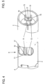
- First 1 shows a schematic side view of an endoscope 1 to which the invention is applicable. How out 1 removable, such an endoscope 1 has an insertion tube 2 which is arranged on the distal side of a control body 3. The control body 3 serves as the operating unit of the endoscope 1.
- the insertion tube 2 is a cylindrical tube or hose-like structure.
- the insertion tube 2 is described in more detail below in the direction in which it is inserted into a patient.
- the insertion tube 2 is inserted distal end first.
- the insertion tube 2 has a distal angled section A on the distal side.
- the angled section A can be angled laterally relative to the proximal part of the insertion tube 2 by means of one or more control wires (cable or cable pulls).
- the control wire or cable pull (referred to below simply as control wire) is mounted in the interior of the insertion tube 2 on an inner peripheral surface of the insertion tube 2 in the direction in which the insertion tube 2 extends.
- the distal end of the control wire is anchored to the distal side of the bend section A.
- the proximal end of the control wire is connected to a control element arranged in the control body 3 . This control element tensions the control wire in order to bring about a desired angling of the angling section A.
- the insertion tube 2 Proximal to the bend section A, the insertion tube 2 is designed as a flexible tube element that forms a proximal passive flexible section 20 .
- the flexible section 20 follows the angled section A.
- the flexible section 20 is designed in zones with different flexibility along its longitudinal direction.
- the flexible portion 20 has a first zone B, a second zone C and a third zone D when viewed in the proximal direction proximal area.
- the first zone B is preferably provided with the highest flexibility among the zones of the flexible section 20 . Since the first zone B is equipped with a very high level of flexibility, there is no abrupt transition in flexibility between the bend section A and the first zone B.
- the second zone C has less flexibility than the first zone B.
- the third zone D in turn, has less flexibility than the second zone C.
- the insertion tube 2 according to the invention is formed in one piece. That is, at the transition from the bend section A to the flexible section 20, two elements are not joined together. Thus, the distal angulation section A and the proximal passive flexible section 20 with the three zones A, B and C are formed from a single tube or hose.
- the insertion tube 2 is fixed to the distal end of the control body 3 on the proximal side.
- the insertion tube 2 can be fixed to the control body 3, for example by a locking ring, a sealing ring or directly.
- the insertion tube 2 can be glued or screwed to the control body 3, for example.
- the control body 3 has a first steering wheel F as a first control element for controlling a control wire or cable and a second steering wheel G as a second control element for controlling a control wire or cable.
- the first steering wheel F can bend the bending section A in a first plane (e.g. towards and away from the viewer in 1 ).
- the second steering wheel G can bend the bending section A in a second plane, which is perpendicular to the first plane (e.g. in 1 up and down).
- the angled section A can be angled by 200-270 degrees, for example. This is sufficient for most applications. In a special form, the angled section A can even be angled by 300 degrees.
- the insertion tube 2 and its manufacture are described in more detail below.
- the entire insertion tube 2 is formed of a single tubular member or tube member (hereinafter referred to simply as a tubular member).
- the tube element is a tube of preferably relatively hard material.
- a tube made of stainless steel is particularly preferred.
- a tube made of hard plastic can also be used. In principle, however, any material that can be used for medical purposes can be used.
- Cuts are provided in the tubular member by a laser cutting machine, as discussed in more detail below. After the cuts have been made, certain sections of the tubular member are bent, as will be explained in more detail below.
- the production of the main body of the entire insertion tube 2 does not require any further process steps apart from the provision of cuts and bending. After that, the main body of the insertion tube 2 can be provided with a control wire and covered with a jacket element.
- the flexible section 20 forms the proximal part of the insertion tube 2 according to the invention.
- the flexible section 20 has the three zones B, C and D, each with different flexibility.
- FIG 3 shows a possibility for forming one of the three zones B, C and D of the flexible section 20 in a side view.
- the flexible portion 20 is provided with a plurality of cuts S made perpendicular to the axis of the flexible portion 20 . More precisely, the cuts S are made in such a way that a cut 201 from above through the Tubing perpendicular to the axis of the tubing to a depth terminating in front of the central axis region. Also, a cut 202 is made from below through the tubular member perpendicular to the axis of the tubular member to a depth also terminating forward of the central axis region.
- the cuts 201 and 202 are coplanar and their ends face each other across a space 203 left.
- the space 203 is an uncut space in the central axis portion of the tubular member.
- a cut 204 is made from one (e.g. left) side (cut 204 shows a cut from the viewer's side) through the tubular member perpendicular to the axis of the tubular member to a depth which is in front of the Central axis area ends. Furthermore, a cut is made from the opposite (e.g. right) side (this cut is in 3 not shown as it is beyond the plane of the drawing) through the tubular member perpendicular to the axis of the tubular member to a depth also terminating forward of the central axis region. These cuts are also coplanar and their ends also face each other across a space left. This space is also an uncut space in the central axis area of the tubular member.
- the gap 203 between cuts 201 and 202 and the gap between cut 204 and its associated opposite side cut are offset by 90 degrees along the circumferential direction of the tubular member.
- the cuts 201 and 202 and the cuts 204 and its associated cut of the opposite side are adjacent to each other and alternate along the length of the respective zone in the flexible portion 20, cf 3 .
- the flexible section 20 can be bent laterally to its longitudinal axis around the gaps.
- the individual zones B, C and D differ in that the distances between the cuts S in the longitudinal direction and thus the density of the cuts S are designed differently.
- zone B the distance between the cuts S is the smallest.
- zone B the density of cuts S is highest.
- zone C the distance between the cuts S is greater than in zone B.
- zone D the distance between the cuts S is greater than in zone C.
- the flexibility and the bendability in the B zone are higher than in the C zone. Further, the flexibility and the bendability in the C zone are higher than in the D zone. In other words, the flexibility and the bendability of the respective zones at the flexible portion decrease 20 in the proximal direction.
- Zone D is provided with an area on the proximal side that is not provided with cuts. This area forms a transition to the control body J.
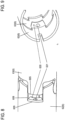
- the transition area from the bend section A to the flexible section 20 is in 2 indicated as region K.
- region K the angled section A ends.
- the wall surface of the tubular member is cut by a cut 70 in the shape of an inverted C letter.
- the cut 70 in the tubular member is cut in the shape of an incomplete circle.
- the circle of cut 70 is uncut on the distal side.
- the uncut distal side of the incision 70 forms a hinge 71 for a tab 72.
- the tab 72 has a lower ear 73, an upper ear 74 and a tab midpiece 75. At an upper The side of the tab center piece 75 borders the lower ear 73 .
- the upper ear 74 adjoins a lower side of the tab center piece 75 .
- the tab 72 is made as follows. The location of the cut 70 is determined. In the middle of the cut 70 a hole 77 is cut. The cut 70 is made by laser as in 2 shown formed.
- the link center piece 75 is supported from the rear, ie from the inside of the tubular element, by a stamp.
- the lower ear 73 is bent inwardly 90 degrees relative to the tab center 75 .
- the bending line of the ear 73 relative to the strap center piece 75 runs parallel to the axis of the tubular element (in figures 2 and 4 in the left and right direction).
- the upper ear 74 is also bent inwardly 90 degrees relative to the tab center 75 .
- the bend line of the ear 74 relative to the tab center 75 is also parallel to the axis of the tubular member.
- the tab center piece 75 is bent 90 degrees inward.
- the bending line of the tab center piece 75 relative to the tubular element runs in the perpendicular sectional plane to the axis of the tubular element (in figures 2 and 4 in the up and down direction).
- the tab center 75 at the hinge 71 is bent inward 90 degrees.
- the tab center piece 75 is bent inward until a distal side edge of the lower ear 73 and a distal side edge of the upper ear 74 abut the inner circumference of the tubular member, see FIG figure 5 ).
- the tab 72 serves as a support for a guide spring 8.
- the proximal surface of the tab center piece 75 forms a stop surface for the distal end of the guide spring 8.
- the two ears 73, 74 support the tab center piece 75 and absorb the compressive forces acting on the guide spring 8 and conduct them to the inner peripheral surface of the tubular member.
- the tab center piece 75 has the central hole 77.
- the hole 77 has a larger diameter than a control wire and a smaller diameter than the guide spring 8.
- the control wire is guided in the flexible section 20 in the guide spring 8 and passes through the hole 70 and extends further into into the bend section A.
- tabs 72 are provided in the number of control wires used (in the present embodiment: four). The tabs 72 are evenly distributed in the circumferential direction of the tube element.
- the bend section A has individual joint members 6 which are arranged in the longitudinal direction of the bend section A.
- the individual joint members 6 can be pivoted relative to one another.
- three joint members 6 arranged one behind the other are shown: a joint 61, a joint 62 proximal to joint 61 and a joint 63 proximal to joint 62.
- the articulation members 6 are identical to each other with the exception of the most distal articulation member 6 and the most proximal articulation member 6.
- the joint member 62 is formed as a tubular portion of said tubular member by laser cutting.
- the joint member 62 has distal boundary lines 601, 602, 603, 604 and 605 and proximal boundary lines 606, 607, 608 and 609 on the circumference of the tubular element.
- the individual distal boundary lines are composed of a head line 601 shaped like a circle, two neck lines 602, two shoulder lines 603, two arm lines 604 and an arm end line 605. More specifically, the distal side of the joint member 62 is formed as follows.
- the circular shaped head line 601 forms an incomplete circle merging into a neck line 602 on each side at the proximal side.
- a shoulder line 603 which is approximately perpendicular to the axis of the tubular member.
- Each of the two shoulder lines 603 is followed by an arm line 604 which runs approximately parallel to the axis of the tubular element in the distal direction.
- the two distal ends of the arm lines 604 are connected by an arm end line 605 which is again perpendicular to the axis of the tubular member.
- the articulated member 62 has a main body 621 from which, towards the distal side, a first head 622, a first arm 623, a second head 622 and a second arm 623 are each rotated by 90 degrees along an imaginary circumferential line perpendicular to the axis of the articulated member 62 runs, protrude.
- the heads 622, 622 extend in a first imaginary plane.
- the arms 623, 623 extend in a second notional plane which is 90 degrees offset from the first notional plane.
- the two heads 622, 622 of the joint member 62 form a pivot axis for the joint member 61 located distally from them.
- Each head 622 is formed by a head line 601 on the distal side. A constriction is formed between the head 622 and the main body 621 by the neck lines 602 . Each head 622 protrudes further in the distal direction than each arm 623.
- the individual proximal boundary lines are composed of a curved root line 606, two bottom lines 607, two straight root lines 608 and a waist line 609. More specifically, the proximal side of the joint member 62 is formed as follows.
- the curved root line 606 forms an incomplete circle that is open on the proximal side. At the open ends of the incomplete circle, the curved root line 606 merges with the bottom line 607, which is approximately perpendicular to the axis of the tubular element.
- Each of the two bottom lines 607 is followed by a straight bottom line 608 which runs in the distal direction approximately parallel to the axis of the tubular element.
- the two distal ends of the straight root lines 608 are connected by a waist line 609 which is again perpendicular to the axis of the tubular member.
- the joint member 62 has two feet 624 on the proximal side of the main body 621, which extend in the proximal direction.
- Each foot 624 has a spanwise straight side at straight foot line 608 and a curved side at curved foot line 606.
- an arm of the proximal link member 63 is arranged to be displaceable in the longitudinal direction.
- a head of the proximal link member 63 is held immovable in the longitudinal direction. At most, a slight movement due to a play between the inner circumference of the curved root line and the outer circumference of the circular shaped head line is possible.
- the waist line 609 is spaced from the arm end line 605 of the proximal joint member 63, as shown in FIG 7 is shown.
- the arm end line 605 and the waist line 609 of the proximal joint member 63 are parallel to each other.
- the bottom line 607 is spaced from the shoulder line 603 of the proximal link member 63, as shown in FIG 7 is shown.
- the bottom line 607 and the shoulder line 603 of the proximally located link member 63 may be parallel to one another or approximately parallel to one another or slightly angled to one another as shown in FIG 7 is shown. Not only has a simple cut line been created between the bottom line 607 and the shoulder line 603 of the proximal hinge member 63, but the material of the tubular member has been cut out as a square piece.
- a respective head 622 forms a coupling portion which is coupled to an adjacent link member 6 .
- the feet 624 form a guide portion which engages an adjacent link 6 such that axial movement of the link 6 relative to each other is permitted.
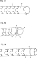
- FIG. 10 shows a plan view of the angled section A with the respective joint members 6.
- the heads 622 of the joint members 6 can be seen in the plan view.
- FIG. 11 shows a side view of the bending section A with the respective articulated members 6.
- the feet 624 of the articulated members 6 can be seen in the side view.
- the distal-most joint member 6 has no head and is in the figures 2 and 10 to 14 shown.
- the most proximal joint member 6 has no foot and is in the figures 2 , 4 and 11 shown.
- the bending section A can be bent in two directions, namely in the Figures 6 and 7 (and 10 ) up and down, with the respective heads 622 of the link members 6 forming bending axes of the link members 6.
- the bending section A in 10 pivotable up and down.
- the flexing portion A is pivotable toward and away from the viewer.
- the waistline 609 forms a hinge portion for a fairlead 630.
- the fairlead 630 extends from the waistline 609.
- a section of material is taken that extends along the straight footlines 608 to the arm end line 605 of the proximally located articulation member 63 .
- the fairlead 630 is hinged at the waist line 609 and is bent inward at 90 degrees.
- the cable guide lug 630 has a central hole 631.
- the hole 631 has a larger diameter than the control wire.
- Each of the joint members 6 has the wire guide tabs 630 with the hole 631 such that the wire guide tabs 630 for a specific control wire are arranged in a row in the longitudinal direction of the bend portion A.
- the cable guide tabs 630 serve as guide projections on which a control wire is supported. Thus, the cable guide tabs 630 guide the control wire assigned to them through the bend section A.
- the joint members 6 may be arranged at the bending portion A with their heads pointing in the proximal direction, as shown in FIG 10 is shown. Alternatively, the joint members 6 may be arranged at the bending portion A with their heads pointing in the distal direction, as shown in FIG 6 is indicated.
- the distal end of the bend section A is in the Figures 12 to 14 shown.
- the joint member 69 of the bend section A located furthest on the distal side can be seen.
- the distal side of the control wire 9 is anchored in this joint member 69 located furthest on the distal side.
- the control wire 9 extends from the control body 3 to the most distal-side joint member 69 of the bending section A.
- control wire 9 The exact attachment of the control wire 9 is in the Figures 15 and 16 shown.
- the control wire 9 is attached to the steering wheel G in the control body 3 .
- the steering wheel G is rotated in a tightening direction, the steering wire 9 is tightened.
- the control wheel G is rotated in the release direction opposite to the tensioning direction, the control wire 9 is released.
- the control wire 9 extends from the control body 3 in the insertion tube 2 to the articulated member 69 and forms a first section 91.
- This first section 91 of the control wire 9 runs along the inner circumference of the insertion tube 2.
- This first section 91 of the control wire 9 is identified by reference numeral 91 in 15 shown.
- On the distal side of the joint member 69 is a peripheral wall of the joint member 69 penetrating slit 691 trained (see 13 ) extending in the longitudinal direction of the link member 69.
- Another similar slot 692 is provided on the distal side of link member 69 diametrically opposite slot 691 .
- the control wire 9 extends in the distal direction on the inner circumference of the joint member 69 and penetrates the slit 691 outward, is wound on the outer circumference of the joint member 69 in the circumferential direction of the joint member 69 up to the slit 692, penetrates the slit 692 inward, and extends at the Inner circumference of the joint member 69 in the proximal direction up to the steering wheel G in the control body 3.
- the control wire 9 is thus divided into a first section 91, which extends from the steering wheel G in the control body 3 to the slot 691, and a second section 92, which extends from the slot 691 on the outer circumference of the joint member 69 in the circumferential direction of the joint member 69 to the slot 692 , and a third portion 93 extending from the slot 692 to the steering wheel G in the control body 3.
- control wire 9 By rotating the control wheel G in the tensioning direction, the control wire 9 is tensioned and the angled section A is thus angled, since the third section 93 anchored on the joint member 69 is pushed in the proximal direction.
- the third section 93 of the control wire 9 thus forms a distal anchoring section of the control wire 9.
- the insertion tube 2 is made by a single tubular element that is laser cut.
- the tube element is made of a relatively hard material such as stainless steel or even a suitable hard plastic.
- the initially hard tubular element becomes flexible due to the cuts, but retains its rigidity.
- the cuts produce the respective lateral incisions S in the proximal passive flexible section 20, the hole 77, the cut 70 in the transition region K, the hole 631, the respective joint members 6 in the distal bending portion A, and the slits 691, 692.
- This order is not to be construed as limiting.
- the slits 691, 692 can be cut in front of the link members 6. The order of the cuts can also be reversed.
- the flexibility and also the rigidity of the tubular element can be controlled by means of the shape, the arrangement and the size of the cuts.
- the location of the respective cuts can be calculated and predetermined beforehand.
- the specified data for the respective cuts can be entered into a programmable laser cutting machine in order to automatically produce the insertion tube 2 .
- the individual joint members 6 are completely cut out and form bodies that are physically separate from one another and are only connected in a form-fitting manner.
- the tabs 72 and the wire guide tabs 630 are bent inward. Thus, the raw body for the insertion tube 2 is completed.
- the control wire 9 can now be inserted and fastened in this raw body for the insertion tube 2 .
- the raw body for the insertion tube 2 can be attached to the control body 3 .
- a coating of preferably metal surrounding the raw body for the insertion tube 2 for shielding the electrical control system can be pulled onto the raw body for the insertion tube 2 and an elastic jacket made of plastic or rubber can be pulled over this.
- the elastic sheath made of plastic or rubber can be subjected to thermal shrinkage.
- the individual joints in the bending section are formed by means of cuts in such a way that they have projections and depressions in the extension direction of the endoscope.
- the projections seat in the indentations of the adjacent joint to allow pivotal movement of the joint.
- the individual joints are connected in a form-fitting manner.
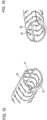
- the bending portion A' is provided with a plurality of cuts 801, 802 made perpendicular to the axis of the bending portion A'. More specifically, the cuts 801, 802 are made such that a cut 801 is made from above through the tubular member perpendicular to the axis of the tubular member to a depth terminating in front of the central axis region. Also, a cut 802 is made from below through the tubular member perpendicular to the axis of the tubular member to a depth also terminating forward of the central axis region.
- the cuts 801 and 802 are coplanar and their ends face each other across a space 803 left.
- the space 803 is an uncut space in the central axis portion of the pipe member.
- the cuts 801 are parallel to each other.
- the cuts 802 are also parallel to one another in an analogous manner.
- the straight cuts 801, 802 function as a hinge and allow the bending movement of the bending portion A'.
- a predefined number of cuts 801 (and of course analogous to 802) lying one behind the other in the longitudinal direction of the bending section A' are combined to form a group.
- cuts 801 each belong to a group, with the number of cuts 801, 802 per group being able to be chosen as suitably as desired.
- the respective group of cuts 801, 802 is delimited in the longitudinal direction of the bending section A' by a ring section 805 with short cuts 811, 812.
- the short cuts 811, 812 are made so that a short cut 811 is made from above through the tubular element perpendicularly in the direction of the axis of the tubular element to a very short depth, as shown in FIG 17 is shown.
- This short depth can be, for example, one tenth to one twentieth of the diameter of the tubular element.
- the length of the short cuts 811, 812 can be selected as appropriate.
- each short cut 812 is made from below in a similar manner to the short cuts 811 from above.
- the cuts 811 are parallel to each other.
- the cuts 812 are also parallel to one another in an analogous manner.
- the short cuts 811 and 812 each form a pair and each lie on a plane and their ends face each other across a left space forming the ring portion 805 .
- the ring portion 805 is a portion of the tubular member that has only a pair of short cuts 811,812.
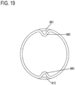
- the material of the tubular element which is adjacent to the respective short cuts 811, 812 forms a band section.
- This band section forms a cable guide tab 880 when bent toward the tube center of the tube member, as shown in FIG 19 is shown.
- a traction cable can thus be guided in the gap formed between the outwardly facing surface of the band portion of the cable guide tab 880 and the longitudinally adjacent inner peripheral surface of the tubular member.
- the straight cuts 801, 802 can be provided at the bending portion A' so that the rigidity is similar to that in the first embodiment.
- the flexible section 20 has a first zone B, a second zone C and a third zone D with different flexibility when viewed in the proximal direction.
- the number of zones or areas with different flexibility is not limited.
- the flexible section 20 can also have more or fewer zones with different flexibility.
- the invention is also applicable to an insertion tube in which the flexible portion 20 has constant flexibility throughout.
- the tubular element of the insertion tube 2 is made of stainless steel.
- the material of the insertion tube 2 can be any sufficiently rigid material, such as a rigid plastic.
- Nitinol a nickel-titanium alloy
- this material has the property of so-called superelasticity, i.e. it can be elastically deformed over a wide range without becoming permanently bent.
- cuts are provided in the tube element by a laser cutting machine. These cuts can be provided very precisely. Therefore, manufacturing by laser is preferred. In principle, however, it is conceivable that these cuts can also be made using other manufacturing processes such as saws, wire saws, etc.
- the bending section A can be bent in two directions, namely in the Figures 6 and 7 up and down.
- the individual joint members 6 can be designed in such a way that their heads 622 are rotated from joint member 6 to joint member 6 by 90 degrees about the axis of the angled section A (axis of the joint members 6). are offset.
- the bend section A can be bent in four bend directions, namely in the Figures 6 and 7 up and down and towards and away from the viewer.
- two control wires 9 can be used, which run in the insertion tube 2 offset by 90 degrees to one another.
- the link member 92 is then provided with four distal slots which are also offset 90 degrees from one another.
- a respective joint member 6 is designed in the form described.
- the invention is not limited to the shape of the joint member 6. It is sufficient if articulated links are cut in the angled section A, which are coupled to one another and allow a deflection movement of the angled section A.
- the invention can advantageously be used with a duodenoscope, a gastroscope, a colonoscope or a similar endoscope.
- the principle of the invention can also be applied to any other type of endoscope.
- the principle of the invention is also applicable to other medical devices using an insertion tube.
Landscapes
- Health & Medical Sciences (AREA)
- Life Sciences & Earth Sciences (AREA)
- Engineering & Computer Science (AREA)
- Surgery (AREA)
- Optics & Photonics (AREA)
- Physics & Mathematics (AREA)
- Biophysics (AREA)
- Veterinary Medicine (AREA)
- Biomedical Technology (AREA)
- Heart & Thoracic Surgery (AREA)
- Animal Behavior & Ethology (AREA)
- General Health & Medical Sciences (AREA)
- Public Health (AREA)
- Pathology (AREA)
- Nuclear Medicine, Radiotherapy & Molecular Imaging (AREA)
- Radiology & Medical Imaging (AREA)
- Medical Informatics (AREA)
- Molecular Biology (AREA)
- Mechanical Engineering (AREA)
- Plasma & Fusion (AREA)
- Manufacturing & Machinery (AREA)
- Hematology (AREA)
- Anesthesiology (AREA)
- Pulmonology (AREA)
- Endoscopes (AREA)
- Instruments For Viewing The Inside Of Hollow Bodies (AREA)
Claims (15)
- Procédé de fabrication d'un tube d'introduction (2) d'un endoscope,le tube d'introduction (2) présentant une section flexible passive proximale (20) et une section coudée distale (A),l'ensemble du tube d'introduction, y compris la section flexible passive (20) et la section coudée (A), étant formé à partir d'un seul élément tubulaire,caractériséen ce qu'une découpe (70, 608) est effectuée dans la surface de paroi de l'élément tubulaire,un côté non découpé de la découpe (70, 608) forme une charnière (71, 609) pour une patte (72, 630),la patte (72, 630) est pliée vers l'intérieur, etla patte comporte un trou découpé (77, 631) pour guider un fil de commande.
- Procédé selon la revendication 1, dans lequel
l'ensemble du tube d'introduction (2), y compris la section flexible passive (20) et la section coudée (A), est découpé au laser à partir d'un seul élément tubulaire. - Procédé selon la revendication 1 ou la revendication 2, dans lequella section coudée distale (A) présente des saillies de guidage (630) courbées vers l'intérieur en tant que languette, sur lesquelles un câble de traction (9) est soutenu en tant que fil de commande ;dans lequel les saillies de guidage (630) pliées vers l'intérieur sont découpées dans la paroi périphérique de la section coudée distale (A) puis pliées vers l'intérieur.
- Procédé selon l'une quelconque des revendications 1 à 3, dans lequelle tube d'insertion (2) comprend, au niveau de la transition (K) entre la partie flexible passive proximale (20) et la section coudée distale (A), une patte (72) recourbée vers l'intérieur en tant que patte sur laquelle un ressort de guidage (8) est supporté ;dans lequel la patte (72) recourbée vers l'intérieur est découpée dans la paroi périphérique du tube d'introduction (2), puis recourbée vers l'intérieur.
- Procédé selon l'une quelconque des revendications 1 à 4, dans lequel plusieurs articulations (6) sont créées par découpe dans la paroi périphérique de la section coudée distale (A).
- Procédé selon la revendication 5, dans lequel
chaque articulation (6) générée par découpe comprend une section de liaison (622) reliée à une articulation (6) adjacente générée par découpe de manière à bloquer un mouvement axial mais pas un mouvement radial des articulations (6) l'une par rapport à l'autre, et une section de guidage (624) engagée avec une articulation (6) adjacente générée par découpe de manière à permettre un mouvement axial des articulations (6) l'une par rapport à l'autre. - Procédé selon l'une quelconque des revendications 1 à 6, dans lequel la section flexible passive proximale (20) est créée par des incisions latérales respectives (S) réalisées perpendiculairement à l'extension longitudinale de l'élément tubulaire.
- Procédé selon la revendication 7, dans lequel,
dans l'extension longitudinale de l'élément tubulaire, la section passive flexible proximale (20) a au moins deux sous-sections (B, C, D) qui ont les incisions latérales respectives (S) à des distances mutuellement différentes dans l'extension longitudinale de l'élément tubulaire. - Procédé selon l'une quelconque des revendications 1 à 8, dans lequel,
à partir d'un corps de contrôle (3) situé à proximité de la section flexible passive proximale (20), un câble de traction (9) est disposé sur le côté périphérique intérieur de l'élément tubulaire, lequel est guidé vers la périphérie extérieure de l'élément tubulaire au niveau d'une articulation (69) la plus distale de la section coudée distale (A) à travers une première fente (691) dans une paroi de l'élément tubulaire, est guidé autour de la circonférence extérieure de l'élément tubulaire vers une deuxième fente (692) dans la paroi de l'élément tubulaire vers la circonférence intérieure de l'élément tubulaire, la deuxième fente (692) étant opposée de 180 degrés à la première fente (691), et est ramené vers le corps de contrôle (3) sur le côté de la circonférence intérieure de l'élément tubulaire. - Endoscope avec un tube d'introduction,le tube d'introduction (2) présentant une section flexible passive proximale (20) et une section coudée distale (A), l'ensemble du tube d'introduction (2), y compris la section flexible passive (20) et la section coudée (A), étant formé d'un seul élément tubulaire,caractériséen ce que, dans la surface de paroi de l'élément tubulaire, un côté non découpé d'une coupe (70, 608) forme une charnière (71, 609) pour une patte (72, 630),la patte (72, 630) est recourbée vers l'intérieur, etla patte présente un trou découpé (77, 631) pour guider un fil de commande.
- Endoscope selon la revendication 10, dans lequel
la section coudée distale (A) comprend des saillies de guidage (630) courbées vers l'intérieur comme la languette, sur lesquelles un câble de traction (9) est supporté comme le fil de commande. - Endoscope selon l'une des revendications 10 ou 11, dans lequel
le tube d'introduction (2) présente, à la transition entre la section flexible passive proximale (20) et la section coudée distale (A), une patte (72) recourbée vers l'intérieur en tant que patte sur laquelle s'appuie un ressort de guidage (8). - Endoscope selon l'une quelconque des revendications 10 à 12, dans lequel plusieurs articulations (6) sont formées dans la paroi périphérique de la section coudée distale (A).
- Endoscope selon la revendication 13, dans lequel
chaque articulation (6) comprend une section de liaison (622) reliée à une articulation adjacente (6) de manière à bloquer un mouvement axial mais pas un mouvement radial des articulations (6) l'une par rapport à l'autre, et une section de guidage (624) en prise avec une articulation adjacente (6) de manière à permettre un mouvement axial des articulations (6) l'une par rapport à l'autre. - Endoscope selon l'une quelconque des revendications 10 à 14, dans lequel,
à partir d'un corps de contrôle (3) disposé de manière proximale par rapport à la section flexible passive proximale (20), un câble de traction (9) est disposé sur le côté périphérique interne de l'élément tubulaire, lequel est guidé au niveau d'une articulation (69) la plus distale de la section coudée distale (A) à travers une première fente (691) dans une paroi de l'élément tubulaire vers la périphérie externe de l'élément tubulaire, est guidé autour de la circonférence extérieure de l'élément tubulaire vers une deuxième fente (692) dans la paroi de l'élément tubulaire vers la circonférence intérieure de l'élément tubulaire, la deuxième fente (692) étant opposée de 180 degrés à la première fente (691), et est ramené vers le corps de contrôle (3) sur le côté de la circonférence intérieure de l'élément tubulaire.
Applications Claiming Priority (2)
| Application Number | Priority Date | Filing Date | Title |
|---|---|---|---|
| DE102017123975.8A DE102017123975A1 (de) | 2017-10-16 | 2017-10-16 | Verfahren zur Herstellung eines Einführschlauches eines Endoskops und Endoskop mit einem Einführschlauch |
| PCT/IB2018/001155 WO2019077402A2 (fr) | 2017-10-16 | 2018-10-15 | Procédé pour la fabrication d'un tuyau d'introduction d'un endoscope et endoscope présentant un tuyau d'introduction |
Publications (3)
| Publication Number | Publication Date |
|---|---|
| EP3697284A2 EP3697284A2 (fr) | 2020-08-26 |
| EP3697284C0 EP3697284C0 (fr) | 2023-08-30 |
| EP3697284B1 true EP3697284B1 (fr) | 2023-08-30 |
Family
ID=64051611
Family Applications (2)
| Application Number | Title | Priority Date | Filing Date |
|---|---|---|---|
| EP18797086.8A Active EP3697284B1 (fr) | 2017-10-16 | 2018-10-15 | Procédé pour la fabrication d'un tuyau d'introduction d'un endoscope et endoscope présentant un tuyau d'introduction |
| EP18796097.6A Active EP3697283B1 (fr) | 2017-10-16 | 2018-10-15 | Procédé servant à fabriquer un tuyau flexible d'insertion d'un endoscope, et endoscope comprenant un tuyau flexible d'insertion |
Family Applications After (1)
| Application Number | Title | Priority Date | Filing Date |
|---|---|---|---|
| EP18796097.6A Active EP3697283B1 (fr) | 2017-10-16 | 2018-10-15 | Procédé servant à fabriquer un tuyau flexible d'insertion d'un endoscope, et endoscope comprenant un tuyau flexible d'insertion |
Country Status (9)
| Country | Link |
|---|---|
| US (2) | US11931001B2 (fr) |
| EP (2) | EP3697284B1 (fr) |
| JP (2) | JP7287954B2 (fr) |
| CN (2) | CN111163677B (fr) |
| AU (2) | AU2018353497B2 (fr) |
| CA (2) | CA3077505C (fr) |
| DE (1) | DE102017123975A1 (fr) |
| ES (2) | ES2963994T3 (fr) |
| WO (2) | WO2019077402A2 (fr) |
Families Citing this family (28)
| Publication number | Priority date | Publication date | Assignee | Title |
|---|---|---|---|---|
| CN110325098A (zh) | 2016-11-28 | 2019-10-11 | 适内有限责任公司 | 具有可分离一次性轴的内窥镜 |
| DE102017123975A1 (de) | 2017-10-16 | 2019-04-18 | Hoya Corporation | Verfahren zur Herstellung eines Einführschlauches eines Endoskops und Endoskop mit einem Einführschlauch |
| CN108577789A (zh) * | 2018-05-17 | 2018-09-28 | 上海安清医疗器械有限公司 | 内窥镜 |
| DE102018127227B4 (de) * | 2018-10-31 | 2022-06-15 | Hoya Corporation | Verfahren zur Herstellung eines Einführschlauches eines Endoskops und Endoskop mit einem Einführschlauch |
| KR102880775B1 (ko) * | 2019-04-01 | 2025-11-07 | 포티메딕스 에셋츠 Ii 비.브이. | 슬롯형 구조체를 갖는 힌지를 포함하는 조종가능한 기구 |
| CN109893073A (zh) * | 2019-04-19 | 2019-06-18 | 广州瑞派医疗器械有限责任公司 | 医用蛇骨管 |
| CN114554930A (zh) * | 2019-08-15 | 2022-05-27 | 奥瑞斯健康公司 | 具有多个弯曲节段的医疗装置 |
| JP7653996B2 (ja) * | 2019-12-19 | 2025-03-31 | ノア メディカル コーポレーション | モジュール式内視鏡用のシステム及び方法 |
| USD1018844S1 (en) | 2020-01-09 | 2024-03-19 | Adaptivendo Llc | Endoscope handle |
| CN111761609B (zh) * | 2020-07-08 | 2022-06-03 | 天津大学 | 基于接触辅助结构的柔性连续体机器人 |
| CN112336297B (zh) * | 2020-10-31 | 2022-06-07 | 同济大学 | 体内导入装置的控制方法、系统和计算机可读存储介质 |
| USD1051380S1 (en) | 2020-11-17 | 2024-11-12 | Adaptivendo Llc | Endoscope handle |
| CN112472004A (zh) * | 2020-12-16 | 2021-03-12 | 杭州思康新医疗科技有限公司 | 一种内窥镜以及用于内窥镜的插入部 |
| GB2636953B (en) * | 2021-01-26 | 2026-01-21 | Versitech Ltd | Coupling joints on tubular spiralling loops of a steerable arm for an endoscope instrument channel |
| USD1031035S1 (en) | 2021-04-29 | 2024-06-11 | Adaptivendo Llc | Endoscope handle |
| USD1070082S1 (en) | 2021-04-29 | 2025-04-08 | Adaptivendo Llc | Endoscope handle |
| US20230016149A1 (en) * | 2021-07-16 | 2023-01-19 | Medtronic, Inc. | Transcatheter valve delivery system with omnidirectional steering and methods of use thereof |
| CN113456231B (zh) * | 2021-07-22 | 2022-08-12 | 上海交通大学 | 基于交叉弯曲梁结构的切口型连续体机器人 |
| USD1066659S1 (en) | 2021-09-24 | 2025-03-11 | Adaptivendo Llc | Endoscope handle |
| US20250090001A1 (en) * | 2021-11-02 | 2025-03-20 | Hoya Corporation | Endoscope with insertion tube having adjacent cuts with unequal spacing and method of manufacturing such an endoscope |
| US20230148846A1 (en) * | 2021-11-17 | 2023-05-18 | Greene Group Industries, Llc | Single Piece Stamped Flexure |
| JP2024033539A (ja) * | 2022-08-30 | 2024-03-13 | 株式会社カネカ | 内視鏡のシャフト |
| CN116077004B (zh) * | 2022-12-05 | 2026-02-17 | 浙江优亿医疗器械股份有限公司 | 一种内窥镜及其弯曲结构 |
| GB2641649A (en) * | 2023-02-03 | 2025-12-10 | Agilis Robotics Ltd | Method of making steerable surgical arm for use in endoscopes during surgical procedures |
| US20240358234A1 (en) * | 2023-04-27 | 2024-10-31 | Covidien Lp | Articulating endoscope with working channel |
| CN116831504A (zh) * | 2023-07-03 | 2023-10-03 | 上海微创微航机器人有限公司 | 柔性结构以及内窥镜插入部 |
| TWM654199U (zh) * | 2024-01-12 | 2024-04-11 | 晉弘科技股份有限公司 | 轉向關節鋼索固定裝置 |
| CN222425963U (zh) * | 2024-04-26 | 2025-02-07 | 湖南省华芯医疗器械有限公司 | 一种被动弯曲段与壳体的连接结构、内窥镜手柄及内窥镜 |
Citations (1)
| Publication number | Priority date | Publication date | Assignee | Title |
|---|---|---|---|---|
| EP0764423B1 (fr) * | 1995-09-22 | 2004-09-29 | Richard Wolf GmbH | Tube pliable et procédé de fabrication |
Family Cites Families (29)
| Publication number | Priority date | Publication date | Assignee | Title |
|---|---|---|---|---|
| WO1993013704A1 (fr) * | 1992-01-09 | 1993-07-22 | Endomedix Corporation | Mini-endoscope bidirectionnel |
| US5438975A (en) * | 1993-03-24 | 1995-08-08 | Machida Endoscope Co., Ltd. | Distal tip of endoscope having spirally coiled control wires |
| JP2600262Y2 (ja) | 1993-05-12 | 1999-10-04 | 株式会社町田製作所 | 内視鏡 |
| US6749560B1 (en) * | 1999-10-26 | 2004-06-15 | Circon Corporation | Endoscope shaft with slotted tube |
| US6340344B1 (en) | 2000-07-18 | 2002-01-22 | Evergreen Medical Incorporated | Endoscope with a removable suction tube |
| JP2002236260A (ja) | 2001-02-07 | 2002-08-23 | Olympus Optical Co Ltd | 内視鏡 |
| ES2274984T3 (es) * | 2001-07-05 | 2007-06-01 | Precision Vascular Systems, Inc. | Dispositivo medico de punta blanda que puede someterse a torsion y metodo para conformarlo. |
| US20060063973A1 (en) | 2004-04-21 | 2006-03-23 | Acclarent, Inc. | Methods and apparatus for treating disorders of the ear, nose and throat |
| JP2007307068A (ja) * | 2006-05-17 | 2007-11-29 | Olympus Corp | 内視鏡挿入部用節輪連結体及びその製造方法 |
| JP5171355B2 (ja) | 2008-03-31 | 2013-03-27 | テルモ株式会社 | 生体内挿入用プローブ装置 |
| US8439898B2 (en) | 2008-06-17 | 2013-05-14 | Usgi Medical, Inc. | Endoscopic tissue anchor deployment |
| JP5258626B2 (ja) * | 2009-02-27 | 2013-08-07 | Hoya株式会社 | 内視鏡案内管装置 |
| DE102009017175B4 (de) | 2009-04-09 | 2011-05-05 | Richard Wolf Gmbh | Verfahren zur Herstellung eines abwinkelbaren Rohrs |
| US20110112365A1 (en) * | 2009-06-03 | 2011-05-12 | Gyrus Acmi, Inc. | Endoscope shaft |
| CN102413863A (zh) * | 2009-10-14 | 2012-04-11 | 奥林巴斯医疗株式会社 | 医疗用挠性管和医疗设备的插入部 |
| KR101911810B1 (ko) * | 2011-12-23 | 2018-10-26 | 삼성전자주식회사 | 내시경 장비에 구비되는 벤딩모듈 및 그 제조 방법 |
| JP6034573B2 (ja) * | 2012-02-28 | 2016-11-30 | テルモ株式会社 | 医療器具用可撓管および医療器具 |
| TW201350075A (zh) | 2012-06-06 | 2013-12-16 | Medical Intubation Tech Corp | 內視鏡的轉向結構 |
| EP2740400A4 (fr) | 2012-06-22 | 2016-01-27 | Olympus Corp | Tube flexible et instrument médical |
| US8967204B2 (en) * | 2012-08-24 | 2015-03-03 | Olympus Medical Systems Corporation | Curved pipe for endoscopes |
| JP5908192B2 (ja) * | 2014-04-08 | 2016-04-26 | オリンパス株式会社 | 内視鏡 |
| EP3138465A4 (fr) | 2014-10-01 | 2018-01-03 | Olympus Corporation | Tube de courbure d'endoscope, et endoscope comprenant un tube de courbure d'endoscope |
| US10363398B2 (en) * | 2014-10-06 | 2019-07-30 | Sanovas Intellectual Property, Llc | Steerable catheter with flexing tip member |
| CN105266752A (zh) * | 2015-09-08 | 2016-01-27 | 上海熠达光电科技有限公司 | 内窥镜弯曲部及一次性内窥镜 |
| CN205197941U (zh) * | 2015-09-08 | 2016-05-04 | 上海熠达光电科技有限公司 | 内窥镜弯曲部及一次性内窥镜 |
| CN105342539A (zh) * | 2015-11-12 | 2016-02-24 | 珠海普生医疗科技有限公司 | 内窥镜弯曲管 |
| WO2018034021A1 (fr) * | 2016-08-19 | 2018-02-22 | オリンパス株式会社 | Endoscope |
| CN107007241A (zh) * | 2017-03-09 | 2017-08-04 | 上海延顺内窥镜有限公司 | 用于内窥镜头端弯曲部的蛇骨 |
| DE102017123975A1 (de) | 2017-10-16 | 2019-04-18 | Hoya Corporation | Verfahren zur Herstellung eines Einführschlauches eines Endoskops und Endoskop mit einem Einführschlauch |
-
2017
- 2017-10-16 DE DE102017123975.8A patent/DE102017123975A1/de not_active Withdrawn
-
2018
- 2018-10-15 EP EP18797086.8A patent/EP3697284B1/fr active Active
- 2018-10-15 CN CN201880063676.1A patent/CN111163677B/zh active Active
- 2018-10-15 WO PCT/IB2018/001155 patent/WO2019077402A2/fr not_active Ceased
- 2018-10-15 ES ES18796097T patent/ES2963994T3/es active Active
- 2018-10-15 WO PCT/IB2018/001154 patent/WO2019077401A2/fr not_active Ceased
- 2018-10-15 AU AU2018353497A patent/AU2018353497B2/en active Active
- 2018-10-15 JP JP2020518811A patent/JP7287954B2/ja active Active
- 2018-10-15 CA CA3077505A patent/CA3077505C/fr active Active
- 2018-10-15 EP EP18796097.6A patent/EP3697283B1/fr active Active
- 2018-10-15 CA CA3077490A patent/CA3077490C/fr active Active
- 2018-10-15 AU AU2018353498A patent/AU2018353498B2/en active Active
- 2018-10-15 ES ES18797086T patent/ES2964032T3/es active Active
- 2018-10-15 JP JP2020518684A patent/JP7202370B2/ja active Active
- 2018-10-15 US US16/652,287 patent/US11931001B2/en active Active
- 2018-10-15 US US16/652,261 patent/US11627866B2/en active Active
- 2018-10-15 CN CN201880063628.2A patent/CN111163676B/zh active Active
Patent Citations (1)
| Publication number | Priority date | Publication date | Assignee | Title |
|---|---|---|---|---|
| EP0764423B1 (fr) * | 1995-09-22 | 2004-09-29 | Richard Wolf GmbH | Tube pliable et procédé de fabrication |
Also Published As
| Publication number | Publication date |
|---|---|
| US20200237189A1 (en) | 2020-07-30 |
| CA3077490C (fr) | 2024-04-23 |
| JP7287954B2 (ja) | 2023-06-06 |
| EP3697283B1 (fr) | 2023-08-30 |
| EP3697284A2 (fr) | 2020-08-26 |
| AU2018353497B2 (en) | 2024-04-04 |
| CA3077505A1 (fr) | 2019-04-25 |
| CN111163677A (zh) | 2020-05-15 |
| WO2019077402A3 (fr) | 2019-07-11 |
| AU2018353497A1 (en) | 2020-04-16 |
| US20200237185A1 (en) | 2020-07-30 |
| ES2964032T3 (es) | 2024-04-03 |
| US11931001B2 (en) | 2024-03-19 |
| JP2020536612A (ja) | 2020-12-17 |
| DE102017123975A1 (de) | 2019-04-18 |
| EP3697283C0 (fr) | 2023-08-30 |
| CA3077490A1 (fr) | 2019-04-25 |
| CN111163677B (zh) | 2024-01-30 |
| CN111163676A (zh) | 2020-05-15 |
| US11627866B2 (en) | 2023-04-18 |
| EP3697283A2 (fr) | 2020-08-26 |
| WO2019077401A3 (fr) | 2019-07-04 |
| EP3697284C0 (fr) | 2023-08-30 |
| CN111163676B (zh) | 2022-08-30 |
| ES2963994T3 (es) | 2024-04-03 |
| AU2018353498A1 (en) | 2020-04-16 |
| CA3077505C (fr) | 2024-03-19 |
| AU2018353498B2 (en) | 2024-04-11 |
| JP2020536608A (ja) | 2020-12-17 |
| WO2019077402A2 (fr) | 2019-04-25 |
| JP7202370B2 (ja) | 2023-01-11 |
| WO2019077401A2 (fr) | 2019-04-25 |
Similar Documents
| Publication | Publication Date | Title |
|---|---|---|
| EP3697284B1 (fr) | Procédé pour la fabrication d'un tuyau d'introduction d'un endoscope et endoscope présentant un tuyau d'introduction | |
| DE102018127227B4 (de) | Verfahren zur Herstellung eines Einführschlauches eines Endoskops und Endoskop mit einem Einführschlauch | |
| EP0764423B2 (fr) | Tube pliable | |
| EP1977677B1 (fr) | Instrument endoscopique | |
| WO2019211456A1 (fr) | Déflexion endoscopique comprenant un mécanisme rabattable distal | |
| DE102005016103B4 (de) | Duodenumstent | |
| DE69029358T2 (de) | Beugevorrichtung | |
| DE69420549T2 (de) | Elastische prothese zur verbreiterung eines gefässes, insbesondere eines blutgefässes, und verfahren zu deren herstellung | |
| EP2571431A1 (fr) | Dispositif médical pour éliminer des calculs | |
| EP3423148B1 (fr) | Électrode à gaine implantable | |
| DE9420821U1 (de) | Lenkbarer elektrophysiologischer Katheter | |
| EP2581031A1 (fr) | Dispositif de déviation | |
| DE102019102599A1 (de) | Endoskop mit distalem Schwenkmechanismus und Feinjustierung | |
| EP3266366B1 (fr) | Laryngoscope adaptatif et spatule adaptative pour un laryngoscope | |
| WO2017025434A1 (fr) | Tête d'endoscope, endoscope, capuchon et procédé de formation d'un capuchon | |
| DE3504824A1 (de) | Endoskop | |
| DE102021113183A1 (de) | Endoskop mit einem Biegeabschnitt mit einer variierenden Länge von Gelenken | |
| DE102016104302A1 (de) | Stent zum einsatz an bifurkationen | |
| DE102008035310A1 (de) | Medizinisches Instrument mit einem flexiblen Dichtungssystem | |
| DE102011009372B3 (de) | Medizinische Vorrichtung mit einer Gitterstruktur und ein Behandlungssystem mit einer derartigen Gitterstruktur | |
| EP3459473A1 (fr) | Instrument | |
| DE10354830B4 (de) | Hochfrequenz-Schneidevorrichtung | |
| EP2667831B1 (fr) | Dispositif médical doté d'une structure en treillis et système de traitement doté d'un tel dispositif | |
| DE202008015763U1 (de) | Instrument für die laparoskopische Chirurgie | |
| DE102008035311A1 (de) | Medizinisches Instrument mit seitlich versetzbarer Dichtung |
Legal Events
| Date | Code | Title | Description |
|---|---|---|---|
| STAA | Information on the status of an ep patent application or granted ep patent |
Free format text: STATUS: UNKNOWN |
|
| STAA | Information on the status of an ep patent application or granted ep patent |
Free format text: STATUS: THE INTERNATIONAL PUBLICATION HAS BEEN MADE |
|
| PUAI | Public reference made under article 153(3) epc to a published international application that has entered the european phase |
Free format text: ORIGINAL CODE: 0009012 |
|
| STAA | Information on the status of an ep patent application or granted ep patent |
Free format text: STATUS: REQUEST FOR EXAMINATION WAS MADE |
|
| 17P | Request for examination filed |
Effective date: 20200331 |
|
| AK | Designated contracting states |
Kind code of ref document: A2 Designated state(s): AL AT BE BG CH CY CZ DE DK EE ES FI FR GB GR HR HU IE IS IT LI LT LU LV MC MK MT NL NO PL PT RO RS SE SI SK SM TR |
|
| AX | Request for extension of the european patent |
Extension state: BA ME |
|
| DAV | Request for validation of the european patent (deleted) | ||
| DAX | Request for extension of the european patent (deleted) | ||
| STAA | Information on the status of an ep patent application or granted ep patent |
Free format text: STATUS: EXAMINATION IS IN PROGRESS |
|
| 17Q | First examination report despatched |
Effective date: 20220614 |
|
| GRAP | Despatch of communication of intention to grant a patent |
Free format text: ORIGINAL CODE: EPIDOSNIGR1 |
|
| STAA | Information on the status of an ep patent application or granted ep patent |
Free format text: STATUS: GRANT OF PATENT IS INTENDED |
|
| INTG | Intention to grant announced |
Effective date: 20230519 |
|
| GRAS | Grant fee paid |
Free format text: ORIGINAL CODE: EPIDOSNIGR3 |
|
| GRAA | (expected) grant |
Free format text: ORIGINAL CODE: 0009210 |
|
| STAA | Information on the status of an ep patent application or granted ep patent |
Free format text: STATUS: THE PATENT HAS BEEN GRANTED |
|
| AK | Designated contracting states |
Kind code of ref document: B1 Designated state(s): AL AT BE BG CH CY CZ DE DK EE ES FI FR GB GR HR HU IE IS IT LI LT LU LV MC MK MT NL NO PL PT RO RS SE SI SK SM TR |
|
| REG | Reference to a national code |
Ref country code: GB Ref legal event code: FG4D Free format text: NOT ENGLISH |
|
| REG | Reference to a national code |
Ref country code: CH Ref legal event code: EP |
|
| REG | Reference to a national code |
Ref country code: DE Ref legal event code: R096 Ref document number: 502018013148 Country of ref document: DE |
|
| REG | Reference to a national code |
Ref country code: IE Ref legal event code: FG4D Free format text: LANGUAGE OF EP DOCUMENT: GERMAN |
|
| U01 | Request for unitary effect filed |
Effective date: 20230831 |
|
| U07 | Unitary effect registered |
Designated state(s): AT BE BG DE DK EE FI FR IT LT LU LV MT NL PT SE SI Effective date: 20230907 |
|
| U20 | Renewal fee for the european patent with unitary effect paid |
Year of fee payment: 6 Effective date: 20231019 |
|
| PG25 | Lapsed in a contracting state [announced via postgrant information from national office to epo] |
Ref country code: GR Free format text: LAPSE BECAUSE OF FAILURE TO SUBMIT A TRANSLATION OF THE DESCRIPTION OR TO PAY THE FEE WITHIN THE PRESCRIBED TIME-LIMIT Effective date: 20231201 |
|
| PG25 | Lapsed in a contracting state [announced via postgrant information from national office to epo] |
Ref country code: IS Free format text: LAPSE BECAUSE OF FAILURE TO SUBMIT A TRANSLATION OF THE DESCRIPTION OR TO PAY THE FEE WITHIN THE PRESCRIBED TIME-LIMIT Effective date: 20231230 |
|
| PG25 | Lapsed in a contracting state [announced via postgrant information from national office to epo] |
Ref country code: RS Free format text: LAPSE BECAUSE OF FAILURE TO SUBMIT A TRANSLATION OF THE DESCRIPTION OR TO PAY THE FEE WITHIN THE PRESCRIBED TIME-LIMIT Effective date: 20230830 Ref country code: NO Free format text: LAPSE BECAUSE OF FAILURE TO SUBMIT A TRANSLATION OF THE DESCRIPTION OR TO PAY THE FEE WITHIN THE PRESCRIBED TIME-LIMIT Effective date: 20231130 Ref country code: IS Free format text: LAPSE BECAUSE OF FAILURE TO SUBMIT A TRANSLATION OF THE DESCRIPTION OR TO PAY THE FEE WITHIN THE PRESCRIBED TIME-LIMIT Effective date: 20231230 Ref country code: HR Free format text: LAPSE BECAUSE OF FAILURE TO SUBMIT A TRANSLATION OF THE DESCRIPTION OR TO PAY THE FEE WITHIN THE PRESCRIBED TIME-LIMIT Effective date: 20230830 Ref country code: GR Free format text: LAPSE BECAUSE OF FAILURE TO SUBMIT A TRANSLATION OF THE DESCRIPTION OR TO PAY THE FEE WITHIN THE PRESCRIBED TIME-LIMIT Effective date: 20231201 |
|
| PG25 | Lapsed in a contracting state [announced via postgrant information from national office to epo] |
Ref country code: PL Free format text: LAPSE BECAUSE OF FAILURE TO SUBMIT A TRANSLATION OF THE DESCRIPTION OR TO PAY THE FEE WITHIN THE PRESCRIBED TIME-LIMIT Effective date: 20230830 |
|
| REG | Reference to a national code |
Ref country code: ES Ref legal event code: FG2A Ref document number: 2964032 Country of ref document: ES Kind code of ref document: T3 Effective date: 20240403 |
|
| PG25 | Lapsed in a contracting state [announced via postgrant information from national office to epo] |
Ref country code: SM Free format text: LAPSE BECAUSE OF FAILURE TO SUBMIT A TRANSLATION OF THE DESCRIPTION OR TO PAY THE FEE WITHIN THE PRESCRIBED TIME-LIMIT Effective date: 20230830 Ref country code: RO Free format text: LAPSE BECAUSE OF FAILURE TO SUBMIT A TRANSLATION OF THE DESCRIPTION OR TO PAY THE FEE WITHIN THE PRESCRIBED TIME-LIMIT Effective date: 20230830 Ref country code: CZ Free format text: LAPSE BECAUSE OF FAILURE TO SUBMIT A TRANSLATION OF THE DESCRIPTION OR TO PAY THE FEE WITHIN THE PRESCRIBED TIME-LIMIT Effective date: 20230830 Ref country code: SK Free format text: LAPSE BECAUSE OF FAILURE TO SUBMIT A TRANSLATION OF THE DESCRIPTION OR TO PAY THE FEE WITHIN THE PRESCRIBED TIME-LIMIT Effective date: 20230830 |
|
| PG25 | Lapsed in a contracting state [announced via postgrant information from national office to epo] |
Ref country code: MC Free format text: LAPSE BECAUSE OF FAILURE TO SUBMIT A TRANSLATION OF THE DESCRIPTION OR TO PAY THE FEE WITHIN THE PRESCRIBED TIME-LIMIT Effective date: 20230830 |
|
| REG | Reference to a national code |
Ref country code: CH Ref legal event code: PL |
|
| REG | Reference to a national code |
Ref country code: DE Ref legal event code: R097 Ref document number: 502018013148 Country of ref document: DE |
|
| PLBE | No opposition filed within time limit |
Free format text: ORIGINAL CODE: 0009261 |
|
| STAA | Information on the status of an ep patent application or granted ep patent |
Free format text: STATUS: NO OPPOSITION FILED WITHIN TIME LIMIT |
|
| PG25 | Lapsed in a contracting state [announced via postgrant information from national office to epo] |
Ref country code: CH Free format text: LAPSE BECAUSE OF NON-PAYMENT OF DUE FEES Effective date: 20231031 |
|
| PG25 | Lapsed in a contracting state [announced via postgrant information from national office to epo] |
Ref country code: CH Free format text: LAPSE BECAUSE OF NON-PAYMENT OF DUE FEES Effective date: 20231031 |
|
| 26N | No opposition filed |
Effective date: 20240603 |
|
| PG25 | Lapsed in a contracting state [announced via postgrant information from national office to epo] |
Ref country code: IE Free format text: LAPSE BECAUSE OF NON-PAYMENT OF DUE FEES Effective date: 20231015 |
|
| U20 | Renewal fee for the european patent with unitary effect paid |
Year of fee payment: 7 Effective date: 20240906 |
|
| PG25 | Lapsed in a contracting state [announced via postgrant information from national office to epo] |
Ref country code: IE Free format text: LAPSE BECAUSE OF NON-PAYMENT OF DUE FEES Effective date: 20231015 |
|
| PG25 | Lapsed in a contracting state [announced via postgrant information from national office to epo] |
Ref country code: CY Free format text: LAPSE BECAUSE OF FAILURE TO SUBMIT A TRANSLATION OF THE DESCRIPTION OR TO PAY THE FEE WITHIN THE PRESCRIBED TIME-LIMIT; INVALID AB INITIO Effective date: 20181015 |
|
| PG25 | Lapsed in a contracting state [announced via postgrant information from national office to epo] |
Ref country code: HU Free format text: LAPSE BECAUSE OF FAILURE TO SUBMIT A TRANSLATION OF THE DESCRIPTION OR TO PAY THE FEE WITHIN THE PRESCRIBED TIME-LIMIT; INVALID AB INITIO Effective date: 20181015 |
|
| U20 | Renewal fee for the european patent with unitary effect paid |
Year of fee payment: 8 Effective date: 20250909 |
|
| PGFP | Annual fee paid to national office [announced via postgrant information from national office to epo] |
Ref country code: GB Payment date: 20250828 Year of fee payment: 8 |
|
| PG25 | Lapsed in a contracting state [announced via postgrant information from national office to epo] |
Ref country code: TR Free format text: LAPSE BECAUSE OF FAILURE TO SUBMIT A TRANSLATION OF THE DESCRIPTION OR TO PAY THE FEE WITHIN THE PRESCRIBED TIME-LIMIT Effective date: 20230830 |
|
| PGFP | Annual fee paid to national office [announced via postgrant information from national office to epo] |
Ref country code: ES Payment date: 20251103 Year of fee payment: 8 |