EP3698003B1 - Dispositif de volet acoustique - Google Patents
Dispositif de volet acoustique Download PDFInfo
- Publication number
- EP3698003B1 EP3698003B1 EP18793187.8A EP18793187A EP3698003B1 EP 3698003 B1 EP3698003 B1 EP 3698003B1 EP 18793187 A EP18793187 A EP 18793187A EP 3698003 B1 EP3698003 B1 EP 3698003B1
- Authority
- EP
- European Patent Office
- Prior art keywords
- sound absorbing
- absorbing material
- acoustic
- layer
- shutter assembly
- Prior art date
- Legal status (The legal status is an assumption and is not a legal conclusion. Google has not performed a legal analysis and makes no representation as to the accuracy of the status listed.)
- Active
Links
Images


Classifications
-
- E—FIXED CONSTRUCTIONS
- E06—DOORS, WINDOWS, SHUTTERS, OR ROLLER BLINDS IN GENERAL; LADDERS
- E06B—FIXED OR MOVABLE CLOSURES FOR OPENINGS IN BUILDINGS, VEHICLES, FENCES OR LIKE ENCLOSURES IN GENERAL, e.g. DOORS, WINDOWS, BLINDS, GATES
- E06B9/00—Screening or protective devices for wall or similar openings, with or without operating or securing mechanisms; Closures of similar construction
- E06B9/02—Shutters, movable grilles, or other safety closing devices, e.g. against burglary
- E06B9/04—Shutters, movable grilles, or other safety closing devices, e.g. against burglary of wing type, e.g. revolving or sliding
-
- E—FIXED CONSTRUCTIONS
- E06—DOORS, WINDOWS, SHUTTERS, OR ROLLER BLINDS IN GENERAL; LADDERS
- E06B—FIXED OR MOVABLE CLOSURES FOR OPENINGS IN BUILDINGS, VEHICLES, FENCES OR LIKE ENCLOSURES IN GENERAL, e.g. DOORS, WINDOWS, BLINDS, GATES
- E06B5/00—Doors, windows, or like closures for special purposes; Border constructions therefor
- E06B5/20—Doors, windows, or like closures for special purposes; Border constructions therefor for insulation against noise
-
- E—FIXED CONSTRUCTIONS
- E06—DOORS, WINDOWS, SHUTTERS, OR ROLLER BLINDS IN GENERAL; LADDERS
- E06B—FIXED OR MOVABLE CLOSURES FOR OPENINGS IN BUILDINGS, VEHICLES, FENCES OR LIKE ENCLOSURES IN GENERAL, e.g. DOORS, WINDOWS, BLINDS, GATES
- E06B7/00—Special arrangements or measures in connection with doors or windows
- E06B7/02—Special arrangements or measures in connection with doors or windows for providing ventilation, e.g. through double windows; Arrangement of ventilation roses
- E06B7/10—Special arrangements or measures in connection with doors or windows for providing ventilation, e.g. through double windows; Arrangement of ventilation roses by special construction of the frame members
-
- G—PHYSICS
- G10—MUSICAL INSTRUMENTS; ACOUSTICS
- G10K—SOUND-PRODUCING DEVICES; METHODS OR DEVICES FOR PROTECTING AGAINST, OR FOR DAMPING, NOISE OR OTHER ACOUSTIC WAVES IN GENERAL; ACOUSTICS NOT OTHERWISE PROVIDED FOR
- G10K11/00—Methods or devices for transmitting, conducting or directing sound in general; Methods or devices for protecting against, or for damping, noise or other acoustic waves in general
- G10K11/16—Methods or devices for protecting against, or for damping, noise or other acoustic waves in general
- G10K11/162—Selection of materials
- G10K11/168—Plural layers of different materials, e.g. sandwiches
-
- F—MECHANICAL ENGINEERING; LIGHTING; HEATING; WEAPONS; BLASTING
- F24—HEATING; RANGES; VENTILATING
- F24F—AIR-CONDITIONING; AIR-HUMIDIFICATION; VENTILATION; USE OF AIR CURRENTS FOR SCREENING
- F24F13/00—Details common to, or for air-conditioning, air-humidification, ventilation or use of air currents for screening
- F24F13/08—Air-flow control members, e.g. louvres, grilles, flaps or guide plates
- F24F13/18—Air-flow control members, e.g. louvres, grilles, flaps or guide plates specially adapted for insertion in flat panels, e.g. in door or window-pane
-
- F—MECHANICAL ENGINEERING; LIGHTING; HEATING; WEAPONS; BLASTING
- F24—HEATING; RANGES; VENTILATING
- F24F—AIR-CONDITIONING; AIR-HUMIDIFICATION; VENTILATION; USE OF AIR CURRENTS FOR SCREENING
- F24F13/00—Details common to, or for air-conditioning, air-humidification, ventilation or use of air currents for screening
- F24F13/24—Means for preventing or suppressing noise
-
- Y—GENERAL TAGGING OF NEW TECHNOLOGICAL DEVELOPMENTS; GENERAL TAGGING OF CROSS-SECTIONAL TECHNOLOGIES SPANNING OVER SEVERAL SECTIONS OF THE IPC; TECHNICAL SUBJECTS COVERED BY FORMER USPC CROSS-REFERENCE ART COLLECTIONS [XRACs] AND DIGESTS
- Y10—TECHNICAL SUBJECTS COVERED BY FORMER USPC
- Y10S—TECHNICAL SUBJECTS COVERED BY FORMER USPC CROSS-REFERENCE ART COLLECTIONS [XRACs] AND DIGESTS
- Y10S454/00—Ventilation
- Y10S454/906—Noise inhibiting means
Definitions
- the present invention relates to an acoustic shutter assembly adapted to cover a window opening in a wall, including at least one window pane arranged in a frame having an inside adapted to be mounted on the wall and an outside adapted to face away from the wall, wherein at least one ventilation duct is arranged in the frame between an outer ventilation opening and an inner ventilation opening, wherein the ventilation duct extends between a first layer of sound absorbing material arranged at the inside of the frame and a second layer of sound absorbing material arranged at the outside of the frame, and wherein the first and second layers of sound absorbing material extend at least substantially in parallel with the window pane.
- WO 2012/164349 discloses an acoustic shutter assembly, including at least one window pane arranged in a frame, wherein at least one ventilation duct is arranged in the frame between an outer ventilation opening and an inner ventilation opening.
- DE 296 08 765 U1 discloses a noise reducing window attachment to be mounted on the outside of an existing window.
- labyrinths are arranged at either side and at the top in order to reduce the entrance of traffic noise, but to allow air exchange. Sound insulation is provided at the bottom.
- this window attachment may reduce the entrance of traffic noise somewhat, in areas of heavy traffic, especially low frequency noise may still be a problem.
- CN104675287 A discloses a daylighting, ventilation and noise reduction window to be mounted on window openings.
- a ventilation noise reducer in the form of a simple labyrinth is arranged on the periphery of the glass window.
- an acoustic shutter assembly which is adapted to cover a window opening in a wall, and in which the ventilation air enters at either side through respective ducts formed between an outer and an inner layer of sound absorbing material.
- the object of the present invention is to provide an acoustic shutter assembly having improved soundproofing properties compared to known solutions, without compromising ventilation properties.
- a number of acoustic reflectors in the form of plate material are arranged between the first and second layers of sound absorbing material so that the ventilation duct is separated into a number of respective ventilation channels formed between the acoustic reflectors, and each ventilation channel changes direction at least once between the outer ventilation opening and the inner ventilation opening, thereby at least substantially blocking any linear path from the outer ventilation opening to the inner ventilation opening.
- the combination of the acoustic reflectors blocking any linear path from the outer ventilation opening to the inner ventilation opening and the first and second layer of sound absorbing material forming the ventilation duct may significantly reduce the noise entering through the acoustic shutter assembly without reducing the ventilation capabilities of the assembly.
- the ventilation duct is lined by means of a first perforated plate covering the first layer of sound absorbing material and a second perforated plate covering the second layer of sound absorbing material so that the acoustic reflectors extend from the first perforated plate to the second perforated plate.
- the perforated plate may serve to hold the sound absorbing material in place and provide a smooth surface of the inside of the ventilation duct, thereby ensuring free movement of ventilation air.
- the perforated plate may preferably be a metal plate and the acoustic reflectors may preferably be fixed to the perforated plates, preferably by welding or soldering, thereby providing increased stability and consequently better sound absorption.
- the first layer of sound absorbing material has a first thickness and the second layer of sound absorbing material has a second thickness, and the second thickness is greater than the first thickness.
- the relatively greater thickness of the second layer of sound absorbing material may ensure that low frequency noise is absorbed
- the relatively smaller thickness of the first layer of sound absorbing material may ensure that the total thickness of the first and second layers of sound absorbing material is relatively thin.
- the second thickness is at least 4/3 of, more preferred at least 3/2 of, and most preferred about the double of, the first thickness.
- each acoustic reflector is V-formed with a first leg extending obliquely towards the outer ventilation opening and a second leg extending obliquely towards the inner ventilation opening, and the first and second leg of each acoustic reflector preferably connect at least approximately midway between the outer ventilation opening and the inner ventilation opening in a top point of the acoustic reflector.
- each outer ventilation opening is covered by a filter in the form of a perforated plate.
- a filter in the form of a perforated plate.
- insects and small particles may be prevented from entering through the acoustic shutter assembly.
- the perforated plate preferably in the form of a metal plate, may also provide further stability to the entire assembly.
- the at least one ventilation duct is formed in an absorption module including a first absorption cassette holding the first layer of sound absorbing material and a second absorption cassette holding the second layer of sound absorbing material.
- each absorption cassette has at least two opposed U-formed profiles holding opposed edges of the corresponding layer of sound absorbing material. Thereby, the layers of sound absorbing material may easily be mounted.
- the frame has four frame members in the form of a top member, a bottom member, a first side member and a second side member, a first ventilation duct is arranged at the first side member and a second ventilation duct is arranged at the second side member.
- ventilation air may easily enter the assembly without rain and dust entering through the ventilation ducts.
- a first shutter is arranged in its open position at the first side member and a second shutter is arranged in its open position at the second side member, and the first and second shutters are arranged displaceably to respective closed positions thereby covering the at least one window pane.
- the shutters may advantageously hide the first and second ventilation ducts in the open position of the shutters.
- the shutters may preferably be electrically operated from inside the building.
- the at least one window pane is separated in a first pane part arranged in its open position at the first side member and a second pane part arranged in its open position at the second side member, and the first and second pane parts are arranged displaceably to respective closed positions in which the first and second pane parts meet each other and covers the window opening.
- the pane parts are arranged displaceably in a plane extending between a plane of the first and second layers of sound absorbing material and a plane in which the first and second shutters are arranged displaceably.
- a first ventilation duct 7 is arranged at the first side member 25 and a second ventilation duct 7 is arranged at the second side member 26.
- Each ventilation duct 7 is arranged in the frame 4 between an outer ventilation opening 8 and an inner ventilation opening 9, and the ventilation duct 7 extends between a first layer 10 of sound absorbing material arranged at the inside 5 of the frame 4 and a second layer 11 of sound absorbing material arranged at the outside 6 of the frame.
- the first and second layers 10, 11 of sound absorbing material extend at least substantially in parallel with the window pane 2,3.
- a number of acoustic reflectors 12 in the form of metal plate material are arranged between the first and second layers 10, 11 of sound absorbing material so that each ventilation duct 7 is separated into a number of respective ventilation channels 13 formed between the acoustic reflectors 12.
- the metal plate material of each acoustic reflector 12 is V-formed with a first leg 16 extending obliquely towards the outer ventilation opening 8 and a second leg 17 extending obliquely towards the inner ventilation opening 9.
- each ventilation channel 13 changes direction between the outer ventilation opening 8 and the inner ventilation opening 9, so that any linear path from the outer ventilation 8 opening to the inner ventilation opening 9 is blocked. This may of course be achieved with many other forms of the acoustic reflectors 12 than the illustrated V-form.
- each acoustic reflector 12 could form an arc.
- the first and second legs 16, 17 of each acoustic reflector 12 connect midway between the outer ventilation opening 8 and the inner ventilation opening 9 in a top point 18 of the acoustic reflector 12.
- each outer ventilation opening 8 is covered by a filter 19 in the form of a perforated plate.
- Each ventilation duct 7 is lined by means of a first perforated plate 14 covering the first layer 10 of sound absorbing material and a second perforated plate 15 covering the second layer 11 of sound absorbing material so that the acoustic reflectors 12 extend from the first perforated plate 14 to the second perforated plate 15.
- the acoustic reflectors 12 are welded to the first and second perforated plates 14, 15.
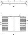
- the first and second layers 10, 11 of sound absorbing material may be made of a PET (Polyethylene terephthalate) felt or any other suitable sound absorbing material. As illustrated in Fig. 10 , between the first perforated plate 14 and the first layer 10 of sound absorbing material and between the second perforated plate 15 and the second layer 11 of sound absorbing material, a sound absorbing foil 29 is arranged that may also act as a vapour barrier.
- the first layer 10 of sound absorbing material has a first thickness t and the second layer 11 of sound absorbing material has a second thickness T, and the second thickness T is greater than the first thickness t.
- the first thickness t is 20 millimetres and the second thickness T is 40 millimetres.
- the second thickness T is preferably at least 4/3 of, more preferred at least 3/2 of, and most preferred about the double of, the first thickness t.
- the at least one ventilation duct 7 is formed in an absorption module 20 including a first absorption cassette 21 holding the first layer 10 of sound absorbing material and a second absorption cassette 22 holding the second layer 11 of sound absorbing material.
- Figs. 4 to 8 illustrate the absorption module 20 without the first and second layers 10, 11 of sound absorbing material.
- each absorption cassette 21, 22 has two opposed U-formed profiles 23 adapted to hold opposed edges of the corresponding layer 10, 11 of sound absorbing material.
- the U-formed profiles 23 are welded to the vertical side edges of the first and second perforated plates 14, 15.
- first and second perforated plates 14, 15 are held together at a distance from each other in that they are welded to a U-formed profile 31.
- the arrangement of the layers 10, 11 of sound absorbing material in the absorption cassettes 21, 22 is illustrated in Fig. 3 .
- a first shutter 27 is arranged in its open position at the first side member 25 and a second shutter 28 is arranged in its open position at the second side member 26.
- the first and second shutters 27, 28 are arranged displaceably to respective closed positions in which the shutters abut each other centrally and the window pane 2, 3 is covered.
- the window pane 2, 3 is separated in a first pane part 2 which is slideable to its open position at the first side member 25 and a second pane part 3 which is slideable to its open position at the second side member 26.
- the first and second pane parts 2, 3 are in their closed positions in which the first and second pane parts 2, 3 meet each other and covers the window opening.
- the pane parts 2, 3 are arranged displaceably in a plane extending between the second layer 11 of sound absorbing material and a plane in which the first and second shutters 27, 28 are arranged displaceably.
- the front side of the second layer 11 of sound absorbing material is covered by means of a metal plate 30 in order to cover the outside of the sound absorbing material when the first and second shutters 27, 28 are moved to their closed positions.
- the first and second shutters 27, 28 are arranged displaceably in that a bracket 32 mounted at the upper edge of each shutter 27, 28 carries first rollers 33 rolling in a track 34 of the frame 4 and second rollers 35 running on either side of a track 36 of the frame 4. Pins 46 at the lower edge of each shutter 27, 28 steer in a groove 47 of the frame 4.
- the first and second shutters 27, 28 are driven by means of an electric motor 37 by means of a wire 38 driven by the electric motor 37.
- the wire 38 runs over a first wire roller 39 driven by the motor and a second opposed wire roller 40.
- the wire 38 is tensioned by means of a tensioning roller 41 held by a spring 42.
- the wire 38 is connected to each shutter 27, 28 by means of respective brackets 43.
- the first and second pane parts 2, 3 are arranged manually displaceably in that rollers 44 at the top of each pane part 2, 3 roll in a track 45 of the frame 4.
- a lower edge 48 of the first and second pane parts 2, 3 steers in a groove 49 of the frame 4.
Landscapes
- Engineering & Computer Science (AREA)
- Structural Engineering (AREA)
- Civil Engineering (AREA)
- Chemical & Material Sciences (AREA)
- Combustion & Propulsion (AREA)
- Mechanical Engineering (AREA)
- General Engineering & Computer Science (AREA)
- Physics & Mathematics (AREA)
- Acoustics & Sound (AREA)
- Multimedia (AREA)
- Architecture (AREA)
- Special Wing (AREA)
Claims (10)
- Ensemble volet acoustique (1) apte à recouvrir une ouverture de fenêtre dans une paroi, incluant au moins une vitre de fenêtre (2, 3) agencée dans un cadre (4) présentant un intérieur (5) apte à être monté sur la paroi et un extérieur (6) apte à être orienté à l'opposé de la paroi, dans lequel au moins un conduit de ventilation (7) est agencé dans le cadre (4) entre une ouverture de ventilation extérieure (8) et une ouverture de ventilation intérieure (9), dans lequel le conduit de ventilation (7) s'étend entre une première couche (10) de matériau insonorisant agencée à l'intérieur (5) du cadre (4) et une seconde couche (11) de matériau insonorisant agencée à l'extérieur (6) du cadre, et dans lequel les première et seconde couches (10, 11) de matériau insonorisant s'étendent au moins sensiblement parallèlement à la vitre de fenêtre (2, 3), dans lequel
un nombre de réflecteurs acoustiques (12) sous la forme d'un matériau de plaque sont agencés entre les première et seconde couches (10, 11) de matériau insonorisant de sorte que le conduit de ventilation (7) soit séparé en un nombre de canaux de ventilation (13) respectifs formés entre les réflecteurs acoustiques (12), et en ce que chaque canal de ventilation (13) change de direction au moins une fois entre l'ouverture de ventilation extérieure (8) et l'ouverture de ventilation intérieure (9), en bloquant de ce fait au moins sensiblement tout trajet linéaire depuis l'ouverture de ventilation extérieure (8) jusqu'à l'ouverture de ventilation intérieure (9). - Ensemble volet acoustique selon la revendication 1, dans lequel le conduit de ventilation (7) est aligné au moyen d'une première plaque perforée (14) recouvrant la première couche (10) de matériau insonorisant et d'une seconde plaque perforée (15) recouvrant la seconde couche (11) de matériau insonorisant de sorte que les réflecteurs acoustiques (12) s'étendent depuis la première plaque perforée (14) jusqu'à la seconde plaque perforée (15).
- Ensemble volet acoustique selon la revendication 1 ou 2, dans lequel la première couche (10) de matériau insonorisant présente une première épaisseur (t) et la seconde couche (11) de matériau insonorisant présente une seconde épaisseur (T), dans lequel la seconde épaisseur (T) est supérieure à la première épaisseur (t), et dans lequel la seconde épaisseur (T) est de préférence au moins 4/3, plus préférentiellement 3/2, et le plus préférentiellement environ le double de la première épaisseur (t).
- Ensemble volet acoustique selon l'une quelconque des revendications précédentes, dans lequel le matériau de plaque de chaque réflecteur acoustique (12) est en forme de V avec une première branche (16) s'étendant obliquement vers l'ouverture de ventilation extérieure (8) et une seconde branche (17) s'étendant obliquement vers l'ouverture de ventilation intérieure (9), et dans lequel les première et seconde branches (16, 17) de chaque réflecteur acoustique (12) se rejoignent de préférence au moins approximativement au milieu entre l'ouverture de ventilation extérieure (8) et l'ouverture de ventilation intérieure (9) à un point de sommet (18) du réflecteur acoustique (12).
- Ensemble volet acoustique selon l'une quelconque des revendications précédentes, dans lequel chaque ouverture de ventilation extérieure (8) est recouverte d'un filtre (19) sous la forme d'une plaque perforée.
- Ensemble volet acoustique selon l'une quelconque des revendications précédentes, dans lequel l'au moins un conduit de ventilation (7) est formé dans un module d'absorption (20) incluant une première cassette d'absorption (21) contenant la première couche (10) de matériau insonorisant et une seconde cassette d'absorption (22) contenant la seconde couche (11) de matériau insonorisant, et dans lequel chaque cassette d'absorption (21, 22) présente au moins deux profils en forme de U opposés (23) contenant des bords opposés de la couche (10, 11) correspondante de matériau insonorisant.
- Ensemble volet acoustique selon l'une quelconque des revendications précédentes, dans lequel le cadre (4) présente quatre organes de cadre sous la forme d'un organe supérieur (23), d'un organe inférieur (24), d'un premier organe latéral (25) et d'un second organe latéral (26), dans lequel un premier conduit de ventilation (7) est agencé au niveau du premier organe latéral (25) et un second conduit de ventilation (7) est agencé au niveau du second organe latéral (26).
- Ensemble volet acoustique selon la revendication 7, dans lequel un premier volet (27) est agencé à sa position ouverte au niveau du premier organe latéral (25) et un second volet (28) est agencé à sa position ouverte au niveau du second organe latéral (26), et dans lequel les premier et second volets (27, 28) sont agencés, de manière à pouvoir être déplacés, à des positions fermées respectives en recouvrant de ce fait l'au moins une vitre de fenêtre (2, 3).
- Ensemble volet acoustique selon la revendication 7 ou 8, dans lequel l'au moins une vitre de fenêtre (2, 3) est séparée en une première partie de vitre (2) agencée à sa position ouverte au niveau du premier organe latéral (25) et une seconde partie de vitre (3) agencée à sa position ouverte au niveau du second organe latéral (26), et dans lequel les première et seconde parties de vitre (2, 3) sont agencées, de manière à pouvoir être déplacées, à des positions fermées respectives auxquelles les première et seconde parties de vitre (2, 3) se rejoignent et recouvrent l'ouverture de fenêtre.
- Ensemble volet acoustique selon les revendications 8 et 9, dans lequel les parties de vitre (2, 3) sont agencées, de manière à pouvoir être déplacées, dans un plan s'étendant entre un plan des première et seconde couches (10, 11) de matériau insonorisant et un plan dans lequel les premier et second volets (27, 28) sont agencés de manière à pouvoir être déplacés.
Applications Claiming Priority (2)
| Application Number | Priority Date | Filing Date | Title |
|---|---|---|---|
| DKPA201770795 | 2017-10-18 | ||
| PCT/EP2018/077759 WO2019076730A1 (fr) | 2017-10-18 | 2018-10-11 | Ensemble obturateur acoustique |
Publications (2)
| Publication Number | Publication Date |
|---|---|
| EP3698003A1 EP3698003A1 (fr) | 2020-08-26 |
| EP3698003B1 true EP3698003B1 (fr) | 2021-07-28 |
Family
ID=63998688
Family Applications (1)
| Application Number | Title | Priority Date | Filing Date |
|---|---|---|---|
| EP18793187.8A Active EP3698003B1 (fr) | 2017-10-18 | 2018-10-11 | Dispositif de volet acoustique |
Country Status (5)
| Country | Link |
|---|---|
| US (1) | US11566466B2 (fr) |
| EP (1) | EP3698003B1 (fr) |
| CA (1) | CA3079296A1 (fr) |
| DK (1) | DK3698003T3 (fr) |
| WO (1) | WO2019076730A1 (fr) |
Families Citing this family (2)
| Publication number | Priority date | Publication date | Assignee | Title |
|---|---|---|---|---|
| CN217822073U (zh) * | 2022-06-30 | 2022-11-15 | 阳光电源股份有限公司 | 消音组件和新能源设备 |
| KR102797090B1 (ko) * | 2023-09-15 | 2025-04-18 | (주)이오창호 | 소음 저감형 창호 시스템 |
Family Cites Families (29)
| Publication number | Priority date | Publication date | Assignee | Title |
|---|---|---|---|---|
| US979267A (en) * | 1910-09-17 | 1910-12-20 | Charles Benton Dix | Window attachment. |
| US1783276A (en) * | 1929-02-21 | 1930-12-02 | Howard R Bliss | Sound-controlling ventilating device |
| US1865677A (en) * | 1929-07-19 | 1932-07-05 | Buffalo Forge Co | Sound deadener |
| US1990520A (en) * | 1931-06-04 | 1935-02-12 | Walter D Binger | Noise excluding apparatus |
| US1929595A (en) * | 1931-10-22 | 1933-10-10 | Truscon Steel Co | Sound intercepting ventilator |
| US2704504A (en) * | 1950-02-02 | 1955-03-22 | Arthur O Wilkening | Sound trap and air transfer device |
| US2676678A (en) * | 1951-01-19 | 1954-04-27 | Level Line Ceilings Inc | Wall and wall element |
| US3378100A (en) * | 1965-10-18 | 1968-04-16 | Air Filter Corp | Sound attenuator |
| US3452477A (en) * | 1967-10-06 | 1969-07-01 | John H Sassano | Exterior sliding window shutters |
| FR2318300A1 (fr) | 1975-07-18 | 1977-02-11 | Segic | Element prefabrique d'isolation a rapporter sur une baie de batiment existante et procede de montage |
| US4363351A (en) * | 1980-03-10 | 1982-12-14 | George Eriksen | Thermal insulating shutter assembly |
| US4454691A (en) * | 1981-10-02 | 1984-06-19 | Mitchell Robert A | Apparatus for insulating windows and the like |
| CA2164663C (fr) * | 1994-12-20 | 1999-08-10 | David B. Martin | Panneau insonorisant agrafable |
| DE29608765U1 (de) | 1996-05-15 | 1997-09-18 | Haunschild, Erwin, Dipl.-Ing., 96476 Rodach | Vorbaufenster zur Reduzierung der Lärmbelästigung bei geöffneten Fenstern |
| DE19751959A1 (de) | 1997-11-24 | 1999-06-02 | Christian Hirschfelder | Schallschutzkonstruktion |
| GB9920883D0 (en) * | 1999-09-03 | 1999-11-10 | Titon Hardware | Ventilation assemblies |
| US6589112B2 (en) * | 2000-12-29 | 2003-07-08 | Evan Ruach | Duct silencer |
| CN2816299Y (zh) | 2003-09-24 | 2006-09-13 | 上海创静环保技术工程有限公司 | 组合式底部消声通风隔声窗 |
| US7562743B2 (en) * | 2004-12-02 | 2009-07-21 | Quietly Making Noise, Llc | Acoustical window and door covering |
| CN101215950A (zh) | 2007-01-05 | 2008-07-09 | 钟超英 | 环保节能通风消音窗 |
| JP4935443B2 (ja) * | 2007-03-19 | 2012-05-23 | 株式会社日立製作所 | 電子機器の吸音構造 |
| GB0915517D0 (en) * | 2009-09-04 | 2009-10-07 | Ove Arup & Partners Internat L | Sound attenuation air vent |
| EP2715027A4 (fr) * | 2011-05-31 | 2015-07-08 | Fraunhofer Ges Forschung | Élément de façade |
| US20150176327A1 (en) * | 2013-12-19 | 2015-06-25 | Green Winows Corp. | Green Windows System |
| US9493949B2 (en) * | 2014-03-20 | 2016-11-15 | Vanair Design | Panel and panel structure for ventilation and both reactive and dissipative sound dampening |
| CN104675287A (zh) | 2014-12-15 | 2015-06-03 | 安徽三星环保装备制造有限公司 | 采光通风消音窗 |
| FR3035432A1 (fr) * | 2015-04-21 | 2016-10-28 | Sapa Building Systems France | Fenetre comprenant un dispositif d’amortissement acoustique |
| US10244662B2 (en) * | 2015-12-11 | 2019-03-26 | International Business Machines Corporation | Method and apparatus for acoustical noise reduction and distributed airflow |
| CN106677685B (zh) | 2017-01-19 | 2018-05-29 | 吴光明 | 一种通风采光消音窗 |
-
2018
- 2018-10-11 WO PCT/EP2018/077759 patent/WO2019076730A1/fr not_active Ceased
- 2018-10-11 US US16/757,164 patent/US11566466B2/en active Active
- 2018-10-11 DK DK18793187.8T patent/DK3698003T3/da active
- 2018-10-11 EP EP18793187.8A patent/EP3698003B1/fr active Active
- 2018-10-11 CA CA3079296A patent/CA3079296A1/fr active Pending
Also Published As
| Publication number | Publication date |
|---|---|
| EP3698003A1 (fr) | 2020-08-26 |
| CA3079296A1 (fr) | 2019-04-25 |
| DK3698003T3 (da) | 2021-11-01 |
| WO2019076730A1 (fr) | 2019-04-25 |
| US11566466B2 (en) | 2023-01-31 |
| US20200240203A1 (en) | 2020-07-30 |
Similar Documents
| Publication | Publication Date | Title |
|---|---|---|
| EP3698003B1 (fr) | Dispositif de volet acoustique | |
| JP5977639B2 (ja) | 開閉装置 | |
| JP5231596B2 (ja) | 住宅用防雨パネル | |
| JP5452927B2 (ja) | フレキシブルカーテンを備えた高速ドア | |
| JP6644654B2 (ja) | 建物開口部の上部排水構造 | |
| KR101318730B1 (ko) | 복합 여닫이 창호 | |
| JP4691172B2 (ja) | 換気フード | |
| JP2010121311A (ja) | 建物の窓用サイドバイザー | |
| KR101981600B1 (ko) | 빗물차단부재를 구비하는 창구조 | |
| JP6140454B2 (ja) | 開口部の防水装置 | |
| US4425739A (en) | Sliding panel with sound-trap framing | |
| JP5197450B2 (ja) | ガラリ戸付き建物 | |
| KR20180134240A (ko) | 캠핑카용 창문 | |
| JP4231753B2 (ja) | 開閉体の構造 | |
| JP6140455B2 (ja) | 防水装置のシート | |
| JP3947696B2 (ja) | 開閉装置 | |
| JP2021025275A (ja) | 雨防止カバーおよび止水装置 | |
| JP5995559B2 (ja) | 開口部装置 | |
| NL2016894B1 (en) | Window or door covering assembly | |
| JP6426421B2 (ja) | シャッター | |
| US20080141600A1 (en) | Molding system for accordion hurricane shutters | |
| JP2008049031A (ja) | 窓等の開口部の遮音構造 | |
| JP2018087441A (ja) | 大扉装置 | |
| JP5995560B2 (ja) | 開口部装置 | |
| JPS6013995Y2 (ja) | 両引き戸付、密閉、換気調整自在ドア− |
Legal Events
| Date | Code | Title | Description |
|---|---|---|---|
| STAA | Information on the status of an ep patent application or granted ep patent |
Free format text: STATUS: UNKNOWN |
|
| STAA | Information on the status of an ep patent application or granted ep patent |
Free format text: STATUS: THE INTERNATIONAL PUBLICATION HAS BEEN MADE |
|
| PUAI | Public reference made under article 153(3) epc to a published international application that has entered the european phase |
Free format text: ORIGINAL CODE: 0009012 |
|
| STAA | Information on the status of an ep patent application or granted ep patent |
Free format text: STATUS: REQUEST FOR EXAMINATION WAS MADE |
|
| 17P | Request for examination filed |
Effective date: 20200513 |
|
| AK | Designated contracting states |
Kind code of ref document: A1 Designated state(s): AL AT BE BG CH CY CZ DE DK EE ES FI FR GB GR HR HU IE IS IT LI LT LU LV MC MK MT NL NO PL PT RO RS SE SI SK SM TR |
|
| AX | Request for extension of the european patent |
Extension state: BA ME |
|
| DAV | Request for validation of the european patent (deleted) | ||
| DAX | Request for extension of the european patent (deleted) | ||
| GRAP | Despatch of communication of intention to grant a patent |
Free format text: ORIGINAL CODE: EPIDOSNIGR1 |
|
| STAA | Information on the status of an ep patent application or granted ep patent |
Free format text: STATUS: GRANT OF PATENT IS INTENDED |
|
| INTG | Intention to grant announced |
Effective date: 20210211 |
|
| GRAS | Grant fee paid |
Free format text: ORIGINAL CODE: EPIDOSNIGR3 |
|
| GRAA | (expected) grant |
Free format text: ORIGINAL CODE: 0009210 |
|
| STAA | Information on the status of an ep patent application or granted ep patent |
Free format text: STATUS: THE PATENT HAS BEEN GRANTED |
|
| AK | Designated contracting states |
Kind code of ref document: B1 Designated state(s): AL AT BE BG CH CY CZ DE DK EE ES FI FR GB GR HR HU IE IS IT LI LT LU LV MC MK MT NL NO PL PT RO RS SE SI SK SM TR |
|
| REG | Reference to a national code |
Ref country code: GB Ref legal event code: FG4D |
|
| REG | Reference to a national code |
Ref country code: CH Ref legal event code: EP |
|
| REG | Reference to a national code |
Ref country code: DE Ref legal event code: R096 Ref document number: 602018020937 Country of ref document: DE |
|
| REG | Reference to a national code |
Ref country code: AT Ref legal event code: REF Ref document number: 1414885 Country of ref document: AT Kind code of ref document: T Effective date: 20210815 |
|
| REG | Reference to a national code |
Ref country code: IE Ref legal event code: FG4D |
|
| REG | Reference to a national code |
Ref country code: DK Ref legal event code: T3 Effective date: 20211026 |
|
| REG | Reference to a national code |
Ref country code: LT Ref legal event code: MG9D |
|
| REG | Reference to a national code |
Ref country code: NL Ref legal event code: MP Effective date: 20210728 |
|
| REG | Reference to a national code |
Ref country code: AT Ref legal event code: MK05 Ref document number: 1414885 Country of ref document: AT Kind code of ref document: T Effective date: 20210728 |
|
| PG25 | Lapsed in a contracting state [announced via postgrant information from national office to epo] |
Ref country code: RS Free format text: LAPSE BECAUSE OF FAILURE TO SUBMIT A TRANSLATION OF THE DESCRIPTION OR TO PAY THE FEE WITHIN THE PRESCRIBED TIME-LIMIT Effective date: 20210728 Ref country code: SE Free format text: LAPSE BECAUSE OF FAILURE TO SUBMIT A TRANSLATION OF THE DESCRIPTION OR TO PAY THE FEE WITHIN THE PRESCRIBED TIME-LIMIT Effective date: 20210728 Ref country code: FI Free format text: LAPSE BECAUSE OF FAILURE TO SUBMIT A TRANSLATION OF THE DESCRIPTION OR TO PAY THE FEE WITHIN THE PRESCRIBED TIME-LIMIT Effective date: 20210728 Ref country code: ES Free format text: LAPSE BECAUSE OF FAILURE TO SUBMIT A TRANSLATION OF THE DESCRIPTION OR TO PAY THE FEE WITHIN THE PRESCRIBED TIME-LIMIT Effective date: 20210728 Ref country code: HR Free format text: LAPSE BECAUSE OF FAILURE TO SUBMIT A TRANSLATION OF THE DESCRIPTION OR TO PAY THE FEE WITHIN THE PRESCRIBED TIME-LIMIT Effective date: 20210728 Ref country code: NL Free format text: LAPSE BECAUSE OF FAILURE TO SUBMIT A TRANSLATION OF THE DESCRIPTION OR TO PAY THE FEE WITHIN THE PRESCRIBED TIME-LIMIT Effective date: 20210728 Ref country code: PT Free format text: LAPSE BECAUSE OF FAILURE TO SUBMIT A TRANSLATION OF THE DESCRIPTION OR TO PAY THE FEE WITHIN THE PRESCRIBED TIME-LIMIT Effective date: 20211129 Ref country code: NO Free format text: LAPSE BECAUSE OF FAILURE TO SUBMIT A TRANSLATION OF THE DESCRIPTION OR TO PAY THE FEE WITHIN THE PRESCRIBED TIME-LIMIT Effective date: 20211028 Ref country code: LT Free format text: LAPSE BECAUSE OF FAILURE TO SUBMIT A TRANSLATION OF THE DESCRIPTION OR TO PAY THE FEE WITHIN THE PRESCRIBED TIME-LIMIT Effective date: 20210728 Ref country code: BG Free format text: LAPSE BECAUSE OF FAILURE TO SUBMIT A TRANSLATION OF THE DESCRIPTION OR TO PAY THE FEE WITHIN THE PRESCRIBED TIME-LIMIT Effective date: 20211028 Ref country code: AT Free format text: LAPSE BECAUSE OF FAILURE TO SUBMIT A TRANSLATION OF THE DESCRIPTION OR TO PAY THE FEE WITHIN THE PRESCRIBED TIME-LIMIT Effective date: 20210728 |
|
| PG25 | Lapsed in a contracting state [announced via postgrant information from national office to epo] |
Ref country code: PL Free format text: LAPSE BECAUSE OF FAILURE TO SUBMIT A TRANSLATION OF THE DESCRIPTION OR TO PAY THE FEE WITHIN THE PRESCRIBED TIME-LIMIT Effective date: 20210728 Ref country code: LV Free format text: LAPSE BECAUSE OF FAILURE TO SUBMIT A TRANSLATION OF THE DESCRIPTION OR TO PAY THE FEE WITHIN THE PRESCRIBED TIME-LIMIT Effective date: 20210728 Ref country code: GR Free format text: LAPSE BECAUSE OF FAILURE TO SUBMIT A TRANSLATION OF THE DESCRIPTION OR TO PAY THE FEE WITHIN THE PRESCRIBED TIME-LIMIT Effective date: 20211029 |
|
| REG | Reference to a national code |
Ref country code: DE Ref legal event code: R097 Ref document number: 602018020937 Country of ref document: DE |
|
| REG | Reference to a national code |
Ref country code: CH Ref legal event code: PL |
|
| PG25 | Lapsed in a contracting state [announced via postgrant information from national office to epo] |
Ref country code: SM Free format text: LAPSE BECAUSE OF FAILURE TO SUBMIT A TRANSLATION OF THE DESCRIPTION OR TO PAY THE FEE WITHIN THE PRESCRIBED TIME-LIMIT Effective date: 20210728 Ref country code: SK Free format text: LAPSE BECAUSE OF FAILURE TO SUBMIT A TRANSLATION OF THE DESCRIPTION OR TO PAY THE FEE WITHIN THE PRESCRIBED TIME-LIMIT Effective date: 20210728 Ref country code: RO Free format text: LAPSE BECAUSE OF FAILURE TO SUBMIT A TRANSLATION OF THE DESCRIPTION OR TO PAY THE FEE WITHIN THE PRESCRIBED TIME-LIMIT Effective date: 20210728 Ref country code: EE Free format text: LAPSE BECAUSE OF FAILURE TO SUBMIT A TRANSLATION OF THE DESCRIPTION OR TO PAY THE FEE WITHIN THE PRESCRIBED TIME-LIMIT Effective date: 20210728 Ref country code: CZ Free format text: LAPSE BECAUSE OF FAILURE TO SUBMIT A TRANSLATION OF THE DESCRIPTION OR TO PAY THE FEE WITHIN THE PRESCRIBED TIME-LIMIT Effective date: 20210728 Ref country code: AL Free format text: LAPSE BECAUSE OF FAILURE TO SUBMIT A TRANSLATION OF THE DESCRIPTION OR TO PAY THE FEE WITHIN THE PRESCRIBED TIME-LIMIT Effective date: 20210728 |
|
| PLBE | No opposition filed within time limit |
Free format text: ORIGINAL CODE: 0009261 |
|
| STAA | Information on the status of an ep patent application or granted ep patent |
Free format text: STATUS: NO OPPOSITION FILED WITHIN TIME LIMIT |
|
| REG | Reference to a national code |
Ref country code: BE Ref legal event code: MM Effective date: 20211031 |
|
| PG25 | Lapsed in a contracting state [announced via postgrant information from national office to epo] |
Ref country code: MC Free format text: LAPSE BECAUSE OF FAILURE TO SUBMIT A TRANSLATION OF THE DESCRIPTION OR TO PAY THE FEE WITHIN THE PRESCRIBED TIME-LIMIT Effective date: 20210728 |
|
| 26N | No opposition filed |
Effective date: 20220429 |
|
| PG25 | Lapsed in a contracting state [announced via postgrant information from national office to epo] |
Ref country code: LU Free format text: LAPSE BECAUSE OF NON-PAYMENT OF DUE FEES Effective date: 20211011 Ref country code: IT Free format text: LAPSE BECAUSE OF FAILURE TO SUBMIT A TRANSLATION OF THE DESCRIPTION OR TO PAY THE FEE WITHIN THE PRESCRIBED TIME-LIMIT Effective date: 20210728 Ref country code: BE Free format text: LAPSE BECAUSE OF NON-PAYMENT OF DUE FEES Effective date: 20211031 |
|
| PG25 | Lapsed in a contracting state [announced via postgrant information from national office to epo] |
Ref country code: LI Free format text: LAPSE BECAUSE OF NON-PAYMENT OF DUE FEES Effective date: 20211031 Ref country code: CH Free format text: LAPSE BECAUSE OF NON-PAYMENT OF DUE FEES Effective date: 20211031 |
|
| PG25 | Lapsed in a contracting state [announced via postgrant information from national office to epo] |
Ref country code: IE Free format text: LAPSE BECAUSE OF NON-PAYMENT OF DUE FEES Effective date: 20211011 |
|
| PG25 | Lapsed in a contracting state [announced via postgrant information from national office to epo] |
Ref country code: CY Free format text: LAPSE BECAUSE OF FAILURE TO SUBMIT A TRANSLATION OF THE DESCRIPTION OR TO PAY THE FEE WITHIN THE PRESCRIBED TIME-LIMIT Effective date: 20210728 |
|
| PG25 | Lapsed in a contracting state [announced via postgrant information from national office to epo] |
Ref country code: HU Free format text: LAPSE BECAUSE OF FAILURE TO SUBMIT A TRANSLATION OF THE DESCRIPTION OR TO PAY THE FEE WITHIN THE PRESCRIBED TIME-LIMIT; INVALID AB INITIO Effective date: 20181011 |
|
| PG25 | Lapsed in a contracting state [announced via postgrant information from national office to epo] |
Ref country code: MK Free format text: LAPSE BECAUSE OF FAILURE TO SUBMIT A TRANSLATION OF THE DESCRIPTION OR TO PAY THE FEE WITHIN THE PRESCRIBED TIME-LIMIT Effective date: 20210728 |
|
| PG25 | Lapsed in a contracting state [announced via postgrant information from national office to epo] |
Ref country code: MT Free format text: LAPSE BECAUSE OF FAILURE TO SUBMIT A TRANSLATION OF THE DESCRIPTION OR TO PAY THE FEE WITHIN THE PRESCRIBED TIME-LIMIT Effective date: 20210728 |
|
| PG25 | Lapsed in a contracting state [announced via postgrant information from national office to epo] |
Ref country code: TR Free format text: LAPSE BECAUSE OF FAILURE TO SUBMIT A TRANSLATION OF THE DESCRIPTION OR TO PAY THE FEE WITHIN THE PRESCRIBED TIME-LIMIT Effective date: 20210728 |
|
| PGFP | Annual fee paid to national office [announced via postgrant information from national office to epo] |
Ref country code: DE Payment date: 20251021 Year of fee payment: 8 |
|
| PGFP | Annual fee paid to national office [announced via postgrant information from national office to epo] |
Ref country code: GB Payment date: 20251022 Year of fee payment: 8 |
|
| PGFP | Annual fee paid to national office [announced via postgrant information from national office to epo] |
Ref country code: DK Payment date: 20251027 Year of fee payment: 8 |
|
| PGFP | Annual fee paid to national office [announced via postgrant information from national office to epo] |
Ref country code: FR Payment date: 20251030 Year of fee payment: 8 |