EP3698111B1 - Dispositif de surveillance de température et appareil domestique équipé d'un dispositif de surveillance de température - Google Patents
Dispositif de surveillance de température et appareil domestique équipé d'un dispositif de surveillance de température Download PDFInfo
- Publication number
- EP3698111B1 EP3698111B1 EP18786322.0A EP18786322A EP3698111B1 EP 3698111 B1 EP3698111 B1 EP 3698111B1 EP 18786322 A EP18786322 A EP 18786322A EP 3698111 B1 EP3698111 B1 EP 3698111B1
- Authority
- EP
- European Patent Office
- Prior art keywords
- temperature
- sensor
- probe
- household appliance
- temperature monitoring
- Prior art date
- Legal status (The legal status is an assumption and is not a legal conclusion. Google has not performed a legal analysis and makes no representation as to the accuracy of the status listed.)
- Active
Links
Images


Classifications
-
- G—PHYSICS
- G01—MEASURING; TESTING
- G01K—MEASURING TEMPERATURE; MEASURING QUANTITY OF HEAT; THERMALLY-SENSITIVE ELEMENTS NOT OTHERWISE PROVIDED FOR
- G01K1/00—Details of thermometers not specially adapted for particular types of thermometer
- G01K1/14—Supports; Fastening devices; Arrangements for mounting thermometers in particular locations
-
- F—MECHANICAL ENGINEERING; LIGHTING; HEATING; WEAPONS; BLASTING
- F24—HEATING; RANGES; VENTILATING
- F24C—DOMESTIC STOVES OR RANGES ; DETAILS OF DOMESTIC STOVES OR RANGES, OF GENERAL APPLICATION
- F24C7/00—Stoves or ranges heated by electric energy
- F24C7/08—Arrangement or mounting of control or safety devices
-
- G—PHYSICS
- G01—MEASURING; TESTING
- G01K—MEASURING TEMPERATURE; MEASURING QUANTITY OF HEAT; THERMALLY-SENSITIVE ELEMENTS NOT OTHERWISE PROVIDED FOR
- G01K1/00—Details of thermometers not specially adapted for particular types of thermometer
- G01K1/08—Protective devices, e.g. casings
-
- G—PHYSICS
- G01—MEASURING; TESTING
- G01K—MEASURING TEMPERATURE; MEASURING QUANTITY OF HEAT; THERMALLY-SENSITIVE ELEMENTS NOT OTHERWISE PROVIDED FOR
- G01K2207/00—Application of thermometers in household appliances
- G01K2207/02—Application of thermometers in household appliances for measuring food temperature
- G01K2207/06—Application of thermometers in household appliances for measuring food temperature for preparation purposes
Definitions
- the invention relates to a temperature monitoring device, in particular for a household appliance, which comprises a temperature sensor.
- the invention also relates to a household appliance with the temperature monitoring device.
- a household appliance which comprises a cooking surface for a cookware and a heating coil arranged on the cooking surface for heating the cookware.
- a switch is also arranged on the cooking surface, on which a temperature sensor and an overheating sensor are arranged in order to control the household appliance depending on the temperature of the cookware.
- the US patent US$5,176,451 discloses a temperature sensor for a heater, which has a solid cylindrical body with upper and lower plates at one end of the cylindrical body. Between the plates an electrical insulator is arranged, in which a thermocouple is arranged, surrounded by another electrical insulator. In addition, a spring is provided which biases the lower plate of the temperature sensor against a mounting element.
- the US disclosure document US 2015/0233770 A1 discloses a temperature sensor for a cooking area, which consists of two cylindrical elements that can be moved telescopically relative to one another, whereby the two elements are pre-tensioned against one another by springs.
- One element is provided with a plate and a arranged temperature detector. Two of the springs can be used to make electrical contact with the temperature detector.
- the US patent US8,162,541 B2 discloses a temperature sensor that has a housing with a housing base.
- a thermistor is preloaded with a spring against a contact on the base of the housing. This spring also serves to electrically contact the thermistor. The contact is also electrically contacted with a spring.
- a cylindrical insulator is provided that encloses the cylindrical housing wall of the sensor on the inside.
- a vehicle heater with a temperature sensor wherein the temperature sensor is designed as a combination sensor which includes an overheating sensor and a control temperature sensor.
- the JP-S61 176826 A a temperature monitoring device for a cooking vessel.
- a temperature sensor is pre-tensioned against a temperature-receiving plate by means of a spring element when a pot is placed on the receiving plate.
- the invention is based on the object of providing an improved temperature monitoring device, in particular for a household appliance.
- the invention is intended to make it possible to more accurately detect the temperature of an object whose temperature is to be monitored.
- the invention is also intended to achieve a high level of reliability.
- the invention is also based on the object of providing a household appliance with an improved temperature monitoring device.
- the temperature monitoring device comprises a first temperature sensor, a sensor housing which partially encloses the first temperature sensor, and a temperature sensing plate connected to the sensor housing.
- the temperature monitoring device further comprises a first sensor spring element which is force-connected to the sensor housing on the one hand and to the first temperature sensor on the other hand in such a way that it permanently pre-tensions the temperature sensor against the temperature sensing plate. Because the sensor housing only partially encloses the first temperature sensor, the first temperature sensor can be pre-tensioned against the temperature sensing plate at the point where it is not enclosed by the sensor housing.
- the temperature monitoring device has a second temperature sensor in addition to the first temperature sensor, the sensor housing partially enclosing the second temperature sensor. Because the sensor housing only partially encloses the second temperature sensor, the second temperature sensor can be pre-tensioned against the temperature sensor plate at the point where it is not enclosed by the sensor housing.
- the invention can achieve increased operational reliability through redundancy of the temperature sensors.
- a further achievable advantage is that the temperature monitoring device can take on two different temperature monitoring tasks, for example as a sensor for temperature control on the one hand and as a sensor for overheating protection on the other.
- “being in force connection” means that the sensor spring element applies a force directly or indirectly to the temperature sensor relative to the sensor housing.
- the fact that the sensor housing is "connected” to the temperature sensing plate means in this case that there is such a direct or indirect mechanical connection between the sensor housing and the temperature sensing plate that the sensor element can be pre-tensioned against the temperature sensing plate by means of the sensor housing.
- the temperature sensing plate is the part of the temperature monitoring device that is intended for contact with the object whose temperature is to be monitored.
- the preferred temperature sensing plate has a side that, in normal use, faces the object whose temperature is to be monitored. Particularly preferably, this side is an outer side of the temperature monitoring device.
- the temperature sensor is preferably pre-tensioned against a side of the temperature sensing plate that is opposite the side that is intended for contact with the object whose temperature is to be monitored.
- the side of the temperature sensing plate against which the temperature sensor is prestressed, is preferably located inside the temperature monitoring device.
- the stated object is achieved by a household appliance having the features of claim 9.
- the household appliance has the temperature monitoring device.
- the preferred sensor housing has an end face spaced from the temperature sensing plate.
- the end face is the surface of the sensor housing facing the temperature sensing plate.
- the end face faces the side of the temperature sensing plate against which the temperature sensor (or in preferred embodiments of the invention discussed further below, several temperature sensors) is or are prestressed.
- spacers are provided between the front face and the temperature sensing plate, for example in the form of one or more projections or webs.
- This spacer(s) can advantageously be used to set the distance between the front face and the temperature sensing plate.
- the spacer(s) are made of the same material as the temperature sensing plate or the sensor housing.
- they can be made in one piece with the temperature sensing plate or in one piece with the sensor housing.
- the area, or in the case of several projections or webs, the sum of the areas with which the web(s) or projections touch the temperature sensing plate, is preferably at most 20%, particularly preferably at most 10%, particularly preferably at most 3% of the area of the temperature sensing plate facing the sensor housing.
- the area, or in the case of several projections or webs, the sum of the areas with which the web or webs or projections touch the sensor housing is preferably at most 20%, particularly preferably at most 10%, particularly preferably at most 3% of the Surface of the sensor housing facing the temperature sensing plate.
- the preferred distance between the temperature sensing plate and the sensor housing is more than 0.1 mm (millimeters), particularly preferably more than 0.3 mm, particularly preferably more than 1 mm, particularly preferably more than 3 mm.
- the temperature sensing plate is part of a cap of the sensor housing.
- cap is to be understood as an object that at least partially encloses the sensor housing; particularly preferably, the cap only partially encloses the sensor housing.
- the sensor housing is preferably firmly connected to the cap, particularly preferably at one or more points on the cap that do not form the temperature sensing plate.
- the cap can, for example, be connected to the sensor housing in a form-fitting, force-fitting or adhesive manner.
- the cap can be equipped with projections that engage in recesses in the sensor housing, or conversely, the sensor housing can be equipped with projections that engage in recesses in the cap.
- the preferred cap is pot-shaped with a base and a jacket.
- the temperature sensing plate forms the base of the cap.
- the jacket of the cap is in contact with the sensor housing.
- the preferred sensor housing consists of a thermally insulating material, preferably a plastic.
- the preferred plastic is non-flammable.
- the preferred plastic is dimensionally stable at temperatures up to 250 °C, preferably up to 350 °C, preferably up to 500 °C.
- the preferred temperature sensing plate consists of a metal, e.g. aluminum or steel.
- the preferred cap is formed in one piece with the temperature sensing plate. It preferably consists of a metal, e.g. aluminum or steel.
- a second sensor spring element is force-connected to the sensor housing on the one hand and to the second temperature sensor on the other hand in such a way that it prestresses the second temperature sensor against the temperature recording plate.
- the first sensor spring element is force-connected not only to the first but also to the second temperature sensor in such a way that it also prestresses the second temperature sensor against the temperature recording plate. Because the second temperature sensor is prestressed against the temperature recording plate, the accuracy and reliability of the temperature measurement of the second temperature sensor can advantageously be increased.
- the preferred sensor housing is provided with a first cavity with which it partially encloses the first temperature sensor.
- a preferred sensor housing is provided with a second cavity with which it partially encloses the second temperature sensor.
- the first and second temperature sensors are partially enclosed by the same first cavity of the sensor housing.
- the first sensor spring element is supported in the first cavity.
- the second sensor spring element is supported in the second cavity or alternatively in the first cavity.
- the first sensor spring element is preferably supported on the first temperature sensor.
- the first sensor spring element is also supported on the second temperature sensor.
- the second sensor spring element is supported on the second temperature sensor.
- a preferred sensor spring element is a helical spring, a spiral spring or a leaf spring.
- the sensor spring element is preferably made of metal, for example spring steel. However, any other type of spring element can also be used, provided that they can produce the prestressing force according to the invention.
- the first or second temperature sensor is a reversible temperature sensor.
- a reversible temperature sensor is a device that reversibly changes a property, particularly preferably an electrical property, for example the electrical conductivity, the electrical capacitance or the electrical inductance, depending on the temperature to which the temperature sensor is exposed.
- the first or the second temperature sensor is an irreversible temperature sensor.
- an irreversible temperature sensor is a device that irreversibly changes a property, particularly preferably an electrical property, for example the electrical resistance, the electrical capacitance or the electrical inductance, depending on the temperature to which the temperature sensor is exposed.
- one of the temperature sensors of the temperature sensor monitoring device according to the invention is a reversible temperature sensor and another temperature sensor of the temperature monitoring device is an irreversible temperature sensor.
- the temperature monitoring device is preferably equipped in such a way that the property that changes depending on the temperature to which the temperature sensor is exposed can be determined and thus evaluated by an evaluation device that can be connected to the temperature monitoring device.
- a preferred reversible temperature sensor is a thermistor, for example a PTC thermistor (positive temperature coefficient thermistor, also known as a thermistor) or an NTC thermistor (negative temperature coefficient thermistor, also known as a thermistor).
- a preferred irreversible temperature sensor is a thermal fuse, which interrupts the flow of current when a predetermined temperature is exceeded.
- the preferred thermal fuse is connected to a conductive melting element that melts above the specified temperature and thereby interrupting an electrical contact.
- the preferred temperature sensors each comprise an electrical supply line and a discharge line, which are preferably led out through the sensor housing.
- a preferred household appliance comprises a cooking area in or on which a cooking vessel can be placed, particularly preferably in such a way that the cooking vessel is in contact with the temperature monitoring device.
- the cooking vessel is in contact with the temperature recording plate of the temperature monitoring device when placed in or on the cooking area.
- the part of the cooking vessel in contact with the temperature monitoring device is preferably a bottom side of the cooking vessel. In the sense of the present invention, the bottom side of the cooking vessel is the lower side of the cooking vessel during normal use.
- the preferred cooking vessel is a pot or a pan.
- the preferred cooking vessel consists predominantly of a metal, e.g. steel or aluminum.
- the preferred temperature monitoring device is in force connection with a cookware contact spring in order to pre-tension the temperature monitoring device when cookware is placed in or on the cooking area, preferably against the bottom side of the cookware.
- the preferred cookware contact spring is a coil spring or a leaf spring. It is preferably made of metal, e.g. spring steel.
- the preferred household appliance comprises a heating means for heating the cookware.
- a heating means for heating the cookware.
- the cookware can be heated by the heating means when it is in or on the cooking area.
- a preferred heating means is an electrical heater, e.g. a heating coil.
- an induction coil can also be used, which induces currents in the cookware by electrical induction, which heat the cookware.
- a preferred household appliance is equipped with a control means, preferably an electrical control circuit, to control the heating medium depending on the temperature determined by the first or second, preferably reversible, temperature sensor. Temperature to be regulated.
- a preferred household appliance comprises a safety device for switching off the heating means when a predetermined temperature is exceeded at the first or second, particularly preferably irreversible, temperature sensor.
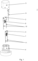
- the temperature monitoring device 1 shown as an example in the figures comprises, as in Figure 1 best seen are two temperature sensors 2, 3, of which the first temperature sensor 2 is a temperature fuse and the second temperature sensor 3 is a thermistor, e.g. an NTC thermistor.
- the temperature sensors 2, 3 are, as in Figure 2 best seen by a sensor housing 4 partially surrounded in such a way that you can see a side opposite the front side of the sensor housing 4 a temperature sensing plate.
- the temperature sensors 2, 3 are each located in a cavity of the sensor housing 4, with each cavity being open towards the temperature sensing plate.
- the temperature sensing plate is the base of a pot-shaped cap 5 which partially encloses the sensor housing 4.
- the temperature sensing plate has a first, outward-facing side which is intended for contact with the object whose temperature is to be monitored.
- the exemplary temperature monitoring device has, as also best shown in Figure 2 , also has a first sensor spring element 6 in the form of a helical spring, which is force-connected to the sensor housing 4 on the one hand and the first temperature sensor 2 on the other hand in such a way that it prestresses the first temperature sensor 2 against the temperature recording plate.
- the first temperature sensor 2 and the first sensor spring element 6 are arranged in a first cavity of the sensor housing 4, and the first sensor spring element 6 is supported on the end of the first cavity which is opposite an opening in the first cavity through which the first temperature sensor 2 contacts the temperature recording plate.
- the first temperature sensor 2 contacts the temperature recording plate on its second, inward-facing side, which is opposite the first temperature recording plate side which is for contact with the object whose temperature is to be monitored.
- the temperature monitoring device has a second sensor spring element 7, also in the form of a helical spring, which is force-connected to the sensor housing 4 on the one hand and to the second temperature sensor 3 on the other hand in such a way that it prestresses the second temperature sensor 3 against the temperature recording plate.
- the second temperature sensor 3 and the second sensor spring element 7 are arranged in a second cavity of the sensor housing 4, and the second sensor spring element 7 is supported on the end of the second cavity which is opposite an opening in the second cavity through which the second temperature sensor 3 contacts the temperature recording plate.
- the second temperature sensor 3 contacts the temperature recording plate on its second, inward-facing side, which is opposite the first temperature recording plate side which is for contact with the object whose temperature is to be monitored.
- the front side of the sensor housing 4 is Figures 1 and 2 clearly visible ribs 8. More precisely, two shorter ribs run perpendicular to a longer rib. The ribs have a height of about 1 mm. As in Figure 2 As shown, the ribs 8 ensure, by their height, a distance between the front side of the sensor housing 4 and the inner side of the temperature recording plate of the cap 5 facing the sensor housing 4.
- the cap 5 is made of a metal with good heat conduction, e.g. aluminum. It is equipped with a grounding line 9.
- the sensor housing 4 is made of a material with good heat insulation, e.g. plastic.
- the hollow cylindrical casing of the cap 5 has inward-reaching projections at several points, which engage in corresponding recesses in the peripheral surface of the sensor housing 4, which is also essentially cylindrical.
- the sensor housing 4 is equipped with four channels, two of which lead from the first and second cavities through the sensor housing 4 to the end of the sensor housing facing away from the temperature recording plate. First 10 and second electrical connection lines 11 of the first 2 and second temperature sensors 3 are guided through these channels.
- FIG 3 shows the temperature monitoring device 1 according to the invention as part of a multi-cooker as an exemplary household appliance 12 according to the invention.
- the household appliance 12 comprises a cooking area on which a cooking pot is placed as cooking utensil 13 in the figure.
- the base of the cooking utensil is in contact with the temperature monitoring device 1, specifically with the temperature recording plate of the temperature monitoring device 1.
- the temperature monitoring device 1 is pre-tensioned against the base of the cooking utensil with a dish contact spring element 14 designed as a helical spring.
- the household appliance 12 also has a Figure 3 not shown heating means in the form of a heating coil or another type of electric or non-electrical heating to heat the cooking utensil 13.
- a control electronics as a control device is connected to both the heating coil and the second temperature sensor, namely via its electrical connection lines 11, in order to control the heating coil depending on the temperature to which the second temperature sensor is exposed.
- This control device is connected to an input unit, e.g. consisting of one or more switches, of the household appliance 12, on which a user of the household appliance 12 can set a desired temperature. This makes it possible for the cookware to be kept at the set temperature with the help of the heating medium and the second temperature sensor.
- the household appliance 12 has an overheating protection device that switches off the heating medium if the first temperature sensor 2 is exposed to a temperature that exceeds a temperature determined by the type of the second temperature sensor. This can be done, for example, by the heating medium being a heating coil or another type of electric heater, and the heating medium being connected in series with the first temperature sensor, the first temperature sensor 2 being designed such that it passes electrical current to the heating medium below the certain temperature, but interrupts the passage when the certain temperature is exceeded.
- the accuracy and reliability of the temperature measurement of the temperature sensor can be advantageously increased.
Landscapes
- Physics & Mathematics (AREA)
- General Physics & Mathematics (AREA)
- Engineering & Computer Science (AREA)
- Chemical & Material Sciences (AREA)
- Combustion & Propulsion (AREA)
- Mechanical Engineering (AREA)
- General Engineering & Computer Science (AREA)
- Measuring Temperature Or Quantity Of Heat (AREA)
- Cookers (AREA)
Claims (12)
- Dispositif de surveillance de température (1) pour un appareil électroménager (12), qui comprend un premier capteur de température (2), un boîtier de capteur (4), qui entoure en partie le premier capteur de température (2), et une plaque de détection de température reliée au boîtier de capteur (4),
caractérisé en ce qu'un premier élément de ressort de capteur (6) est relié de façon à transmettre une force d'une part au boîtier de capteur (4) et d'autre part au premier capteur de température (2), de sorte à pré-contraindre de façon permanente le premier capteur de température (2) contre la plaque de détection de température, et en ce que le dispositif de surveillance de température (1) présente un deuxième capteur de température (3) et le boîtier de capteur (4) entoure en partie le deuxième capteur de température (3). - Dispositif de surveillance de température (1) selon la revendication 1, caractérisé en ce qu'une face d'extrémité du boîtier de capteur (4) est espacée de la plaque de détection de température.
- Dispositif de surveillance de température (1) selon l'une des revendications précédentes, caractérisé en ce que la plaque de détection de température est une partie d'un couvercle (5) sur le boîtier de capteur (4).
- Dispositif de surveillance de température (1) selon l'une des revendications précédentes, caractérisé en ce qu'un deuxième élément de ressort de capteur (7) est relié de façon à transmettre une force d'une part au boîtier de capteur (4) et d'autre part au deuxième capteur de température (3), de sorte à pré-contraindre le deuxième capteur de température (3) contre la plaque de détection de température.
- Dispositif de surveillance de température (1) selon l'une des revendications précédentes, caractérisé en ce que le premier élément de ressort de capteur (2) s'appuie d'une part dans le creux du boîtier de capteur (4) et d'autre part contre le premier capteur de température.
- Dispositif de surveillance de température (1) selon l'une des revendications précédentes, caractérisé en ce que le premier (2) ou le deuxième (3) capteur de température est un capteur de température réversible.
- Appareil électroménager (12) comprenant un dispositif de surveillance de température (1) selon l'une des revendications précédentes.
- Appareil électroménager (12) selon la revendication 7, caractérisé en ce qu'il comprend un emplacement de cuisson, dans ou sur lequel un ustensile de cuisson (13) peut être inséré ou posé, de sorte que l'ustensile de cuisson (13) entre en contact avec le dispositif de surveillance de température (1).
- Appareil électroménager (12) selon la revendication 8, caractérisé en ce que le dispositif de surveillance de température (1) est relié en transmission de force à un élément de ressort de contact d'ustensile (14), de façon à pré-contraindre le dispositif de surveillance de température (1) contre l'ustensile de cuisson (13) lorsque l'ustensile de cuisson (13) est inséré dans ou posé sur l'emplacement de cuisson.
- Appareil électroménager (12) selon la revendication 8 ou 9, caractérisé en ce qu'il comprend un moyen de chauffage pour chauffer l'ustensile de cuisson, et l'ustensile de cuisson (13) peut être chauffé par le moyen de chauffage dans la position insérée dans ou posée sur l'emplacement de cuisson.
- Appareil électroménager (12) selon l'une des revendications 8 à 10, caractérisé en ce que l'appareil électroménager (12) comprend un moyen de régulation pour réguler le moyen de chauffage en fonction de la température détectée par le premier (2) ou le deuxième (3) capteur de température.
- Appareil électroménager (12) selon l'une des revendications 8 à 11, caractérisé en ce que l'appareil électroménager (12) comprend un dispositif de sécurité pour couper le moyen de chauffage lors d'un dépassement d'une température prescrite au niveau du premier (2) ou du deuxième (3) capteur de température.
Applications Claiming Priority (2)
| Application Number | Priority Date | Filing Date | Title |
|---|---|---|---|
| DE102017218554.6A DE102017218554A1 (de) | 2017-10-18 | 2017-10-18 | Temperaturüberwachungsvorrichtung und Haushaltsgerät mit der Temperaturüberwachungsvorrichtung |
| PCT/EP2018/077919 WO2019076763A1 (fr) | 2017-10-18 | 2018-10-12 | Dispositif de surveillance de température et appareil domestique équipé d'un dispositif de surveillance de température |
Publications (3)
| Publication Number | Publication Date |
|---|---|
| EP3698111A1 EP3698111A1 (fr) | 2020-08-26 |
| EP3698111B1 true EP3698111B1 (fr) | 2024-07-31 |
| EP3698111C0 EP3698111C0 (fr) | 2024-07-31 |
Family
ID=63857952
Family Applications (1)
| Application Number | Title | Priority Date | Filing Date |
|---|---|---|---|
| EP18786322.0A Active EP3698111B1 (fr) | 2017-10-18 | 2018-10-12 | Dispositif de surveillance de température et appareil domestique équipé d'un dispositif de surveillance de température |
Country Status (4)
| Country | Link |
|---|---|
| EP (1) | EP3698111B1 (fr) |
| CN (1) | CN111201426A (fr) |
| DE (1) | DE102017218554A1 (fr) |
| WO (1) | WO2019076763A1 (fr) |
Families Citing this family (3)
| Publication number | Priority date | Publication date | Assignee | Title |
|---|---|---|---|---|
| DE102019211311A1 (de) * | 2019-07-30 | 2021-02-04 | BSH Hausgeräte GmbH | Widerstandstemperaturfühleranordnung |
| DE102019124088A1 (de) * | 2019-09-09 | 2021-03-11 | Schaeffler Technologies AG & Co. KG | Elektrische Maschine |
| DE102020207202A1 (de) | 2020-06-09 | 2021-12-09 | BSH Hausgeräte GmbH | Steuergerät und Verfahren zur Temperaturüberwachung eines Steuergeräts |
Family Cites Families (19)
| Publication number | Priority date | Publication date | Assignee | Title |
|---|---|---|---|---|
| US3890588A (en) * | 1972-10-26 | 1975-06-17 | Matsushita Electric Industrial Co Ltd | Water jacket temperature sensor |
| US4614443A (en) * | 1984-11-29 | 1986-09-30 | Societe De Dietrich & Cie | Thermal sensor for chemical reactor |
| JPS61176826A (ja) * | 1985-02-01 | 1986-08-08 | Matsushita Electric Ind Co Ltd | 温度検知装置 |
| DE3818957C2 (de) * | 1988-06-03 | 1998-01-22 | Pfaudler Werke Gmbh | Temperatur-Meßfühleranordnung |
| JPH0464025A (ja) | 1990-07-02 | 1992-02-28 | Matsushita Electric Ind Co Ltd | 調理器用温度センサー |
| FR2685992B1 (fr) * | 1992-01-08 | 1994-04-08 | Seb Sa | Plaque de cuisson electrique a capteur de temperature. |
| FR2760835A1 (fr) * | 1997-03-14 | 1998-09-18 | Siemens Automotive Sa | Capteur de temperature de fluide a double element sensible |
| GB9718246D0 (en) * | 1997-08-28 | 1997-11-05 | Strix Ltd | Electric liquid heating apparatus |
| DE10051867A1 (de) | 2000-10-19 | 2002-04-25 | Eberspaecher J Gmbh & Co | Heizgerät, insbesondere Fahrzeugheizgerät, mit Temperaturfühler |
| US7307246B2 (en) * | 2004-06-28 | 2007-12-11 | General Electric Company | System and method of detecting temperature of a cooking utensil over a radiant cooktop |
| US8162541B2 (en) | 2009-04-06 | 2012-04-24 | Roxanne P. Ostlund, legal representative | Two-terminal temperature sensor with electrically isolated housing |
| CN203024206U (zh) | 2012-12-24 | 2013-06-26 | 陆云庆 | 一种温控电磁炉 |
| US9417138B2 (en) * | 2013-09-10 | 2016-08-16 | Varian Semiconductor Equipment Associates, Inc. | Gas coupled probe for substrate temperature measurement |
| CN203555603U (zh) * | 2013-09-27 | 2014-04-23 | 美的集团股份有限公司 | 用于烹饪器具的温度检测装置及具有其的烹饪器具 |
| CN203705080U (zh) * | 2014-02-11 | 2014-07-09 | 信宜市中为电子有限公司 | 改进结构的温度传感器 |
| US10018514B2 (en) | 2014-02-17 | 2018-07-10 | Haier Us Appliance Solutions, Inc. | Cooktop temperature sensors and methods of operation |
| CN204133128U (zh) * | 2014-09-24 | 2015-02-04 | 佛山市顺德区美的电热电器制造有限公司 | 感温装置和电磁加热的烹饪器具 |
| CN204535881U (zh) * | 2015-04-13 | 2015-08-05 | 佛山市顺德区美的电热电器制造有限公司 | 传感组件及烹饪器具 |
| CN104792433B (zh) * | 2015-04-30 | 2017-07-21 | 佛山市川东磁电股份有限公司 | 一种竖置电阻传感器 |
-
2017
- 2017-10-18 DE DE102017218554.6A patent/DE102017218554A1/de active Pending
-
2018
- 2018-10-12 CN CN201880068059.0A patent/CN111201426A/zh active Pending
- 2018-10-12 EP EP18786322.0A patent/EP3698111B1/fr active Active
- 2018-10-12 WO PCT/EP2018/077919 patent/WO2019076763A1/fr not_active Ceased
Also Published As
| Publication number | Publication date |
|---|---|
| CN111201426A (zh) | 2020-05-26 |
| EP3698111A1 (fr) | 2020-08-26 |
| WO2019076763A1 (fr) | 2019-04-25 |
| DE102017218554A1 (de) | 2019-04-18 |
| EP3698111C0 (fr) | 2024-07-31 |
Similar Documents
| Publication | Publication Date | Title |
|---|---|---|
| DE69422302T2 (de) | Verbesserungen an elektrisch geheisste kochgefässe | |
| DE69126088T2 (de) | Haushaltskochgerät | |
| EP3286804B1 (fr) | Élément de connecteur enfichable comportant un moyen de surveillance de temperature | |
| EP1152639B1 (fr) | Unité de chauffage électrique, particulièrement destiné à des milieux liquides | |
| EP2846344B1 (fr) | Commutateur thermique | |
| EP3698111B1 (fr) | Dispositif de surveillance de température et appareil domestique équipé d'un dispositif de surveillance de température | |
| EP3692559B1 (fr) | Fiche d'alimentation electrique | |
| DE10035745A1 (de) | Temperaturerfassungseinrichtung für einen elektrischen Strahlungsheizkörper | |
| DE2853776A1 (de) | Temperaturabhaengiges elektrisches stromregel- oder -begrenzungsschaltelement fuer elektrische geraete, insbesondere elektrisch beheizte geraete | |
| DE69208705T2 (de) | Elektrothermisches Relais mit Schichtheizelement | |
| DE4300241A1 (fr) | ||
| DE102013216258B4 (de) | Kochfeld | |
| EP0740323B1 (fr) | Thermostat avec un dispositif interrupteur à bimétal commutant en cas de surchauffe | |
| EP0028356A1 (fr) | Indicateur de température pour la signalisation de l'état de température d'une surface de cuisson en verre-céramique | |
| EP1401311B1 (fr) | Recipient de cuisine a fond chauffant | |
| CH671649A5 (fr) | ||
| DE60131255T2 (de) | Temperatursensor | |
| DE10226939A1 (de) | Küchengefäß mit einem Heizboden | |
| EP2506281B1 (fr) | Commutateur thermodépendant avec résistance protectrice | |
| DE102008031389B3 (de) | Temperaturabhängiger Schalter | |
| DE69129468T2 (de) | Elektrischer rohrheizkörper mit einer temperaturkontrolleinrichtung | |
| DE102013214432A1 (de) | Kochfeldvorrichtung | |
| BE1032869B1 (de) | Gargeschirr | |
| DE102017124062A1 (de) | Dampfgenerator mit Sicherheitstemperaturbegrenzervorrichtung | |
| EP2056650B1 (fr) | Support pour un dispositif de chauffage électrique, dispositif de chauffage électrique et procédé de fabrication d'un dispositif de chauffage électrique |
Legal Events
| Date | Code | Title | Description |
|---|---|---|---|
| STAA | Information on the status of an ep patent application or granted ep patent |
Free format text: STATUS: UNKNOWN |
|
| STAA | Information on the status of an ep patent application or granted ep patent |
Free format text: STATUS: THE INTERNATIONAL PUBLICATION HAS BEEN MADE |
|
| PUAI | Public reference made under article 153(3) epc to a published international application that has entered the european phase |
Free format text: ORIGINAL CODE: 0009012 |
|
| STAA | Information on the status of an ep patent application or granted ep patent |
Free format text: STATUS: REQUEST FOR EXAMINATION WAS MADE |
|
| 17P | Request for examination filed |
Effective date: 20200518 |
|
| AK | Designated contracting states |
Kind code of ref document: A1 Designated state(s): AL AT BE BG CH CY CZ DE DK EE ES FI FR GB GR HR HU IE IS IT LI LT LU LV MC MK MT NL NO PL PT RO RS SE SI SK SM TR |
|
| AX | Request for extension of the european patent |
Extension state: BA ME |
|
| DAV | Request for validation of the european patent (deleted) | ||
| DAX | Request for extension of the european patent (deleted) | ||
| STAA | Information on the status of an ep patent application or granted ep patent |
Free format text: STATUS: EXAMINATION IS IN PROGRESS |
|
| 17Q | First examination report despatched |
Effective date: 20220323 |
|
| GRAP | Despatch of communication of intention to grant a patent |
Free format text: ORIGINAL CODE: EPIDOSNIGR1 |
|
| STAA | Information on the status of an ep patent application or granted ep patent |
Free format text: STATUS: GRANT OF PATENT IS INTENDED |
|
| INTG | Intention to grant announced |
Effective date: 20240321 |
|
| GRAS | Grant fee paid |
Free format text: ORIGINAL CODE: EPIDOSNIGR3 |
|
| GRAA | (expected) grant |
Free format text: ORIGINAL CODE: 0009210 |
|
| STAA | Information on the status of an ep patent application or granted ep patent |
Free format text: STATUS: THE PATENT HAS BEEN GRANTED |
|
| AK | Designated contracting states |
Kind code of ref document: B1 Designated state(s): AL AT BE BG CH CY CZ DE DK EE ES FI FR GB GR HR HU IE IS IT LI LT LU LV MC MK MT NL NO PL PT RO RS SE SI SK SM TR |
|
| REG | Reference to a national code |
Ref country code: CH Ref legal event code: EP Ref country code: GB Ref legal event code: FG4D Free format text: NOT ENGLISH |
|
| REG | Reference to a national code |
Ref country code: DE Ref legal event code: R096 Ref document number: 502018014954 Country of ref document: DE |
|
| REG | Reference to a national code |
Ref country code: IE Ref legal event code: FG4D Free format text: LANGUAGE OF EP DOCUMENT: GERMAN |
|
| U01 | Request for unitary effect filed |
Effective date: 20240822 |
|
| U07 | Unitary effect registered |
Designated state(s): AT BE BG DE DK EE FI FR IT LT LU LV MT NL PT RO SE SI Effective date: 20240902 |
|
| U20 | Renewal fee for the european patent with unitary effect paid |
Year of fee payment: 7 Effective date: 20241202 |
|
| PG25 | Lapsed in a contracting state [announced via postgrant information from national office to epo] |
Ref country code: NO Free format text: LAPSE BECAUSE OF FAILURE TO SUBMIT A TRANSLATION OF THE DESCRIPTION OR TO PAY THE FEE WITHIN THE PRESCRIBED TIME-LIMIT Effective date: 20241031 |
|
| PG25 | Lapsed in a contracting state [announced via postgrant information from national office to epo] |
Ref country code: PL Free format text: LAPSE BECAUSE OF FAILURE TO SUBMIT A TRANSLATION OF THE DESCRIPTION OR TO PAY THE FEE WITHIN THE PRESCRIBED TIME-LIMIT Effective date: 20240731 Ref country code: GR Free format text: LAPSE BECAUSE OF FAILURE TO SUBMIT A TRANSLATION OF THE DESCRIPTION OR TO PAY THE FEE WITHIN THE PRESCRIBED TIME-LIMIT Effective date: 20241101 |
|
| PG25 | Lapsed in a contracting state [announced via postgrant information from national office to epo] |
Ref country code: IS Free format text: LAPSE BECAUSE OF FAILURE TO SUBMIT A TRANSLATION OF THE DESCRIPTION OR TO PAY THE FEE WITHIN THE PRESCRIBED TIME-LIMIT Effective date: 20241130 |
|
| PG25 | Lapsed in a contracting state [announced via postgrant information from national office to epo] |
Ref country code: HR Free format text: LAPSE BECAUSE OF FAILURE TO SUBMIT A TRANSLATION OF THE DESCRIPTION OR TO PAY THE FEE WITHIN THE PRESCRIBED TIME-LIMIT Effective date: 20240731 |
|
| PG25 | Lapsed in a contracting state [announced via postgrant information from national office to epo] |
Ref country code: ES Free format text: LAPSE BECAUSE OF FAILURE TO SUBMIT A TRANSLATION OF THE DESCRIPTION OR TO PAY THE FEE WITHIN THE PRESCRIBED TIME-LIMIT Effective date: 20240731 Ref country code: RS Free format text: LAPSE BECAUSE OF FAILURE TO SUBMIT A TRANSLATION OF THE DESCRIPTION OR TO PAY THE FEE WITHIN THE PRESCRIBED TIME-LIMIT Effective date: 20241031 |
|
| PG25 | Lapsed in a contracting state [announced via postgrant information from national office to epo] |
Ref country code: RS Free format text: LAPSE BECAUSE OF FAILURE TO SUBMIT A TRANSLATION OF THE DESCRIPTION OR TO PAY THE FEE WITHIN THE PRESCRIBED TIME-LIMIT Effective date: 20241031 Ref country code: PL Free format text: LAPSE BECAUSE OF FAILURE TO SUBMIT A TRANSLATION OF THE DESCRIPTION OR TO PAY THE FEE WITHIN THE PRESCRIBED TIME-LIMIT Effective date: 20240731 Ref country code: NO Free format text: LAPSE BECAUSE OF FAILURE TO SUBMIT A TRANSLATION OF THE DESCRIPTION OR TO PAY THE FEE WITHIN THE PRESCRIBED TIME-LIMIT Effective date: 20241031 Ref country code: IS Free format text: LAPSE BECAUSE OF FAILURE TO SUBMIT A TRANSLATION OF THE DESCRIPTION OR TO PAY THE FEE WITHIN THE PRESCRIBED TIME-LIMIT Effective date: 20241130 Ref country code: HR Free format text: LAPSE BECAUSE OF FAILURE TO SUBMIT A TRANSLATION OF THE DESCRIPTION OR TO PAY THE FEE WITHIN THE PRESCRIBED TIME-LIMIT Effective date: 20240731 Ref country code: GR Free format text: LAPSE BECAUSE OF FAILURE TO SUBMIT A TRANSLATION OF THE DESCRIPTION OR TO PAY THE FEE WITHIN THE PRESCRIBED TIME-LIMIT Effective date: 20241101 Ref country code: ES Free format text: LAPSE BECAUSE OF FAILURE TO SUBMIT A TRANSLATION OF THE DESCRIPTION OR TO PAY THE FEE WITHIN THE PRESCRIBED TIME-LIMIT Effective date: 20240731 |
|
| PG25 | Lapsed in a contracting state [announced via postgrant information from national office to epo] |
Ref country code: SM Free format text: LAPSE BECAUSE OF FAILURE TO SUBMIT A TRANSLATION OF THE DESCRIPTION OR TO PAY THE FEE WITHIN THE PRESCRIBED TIME-LIMIT Effective date: 20240731 |
|
| PG25 | Lapsed in a contracting state [announced via postgrant information from national office to epo] |
Ref country code: CZ Free format text: LAPSE BECAUSE OF FAILURE TO SUBMIT A TRANSLATION OF THE DESCRIPTION OR TO PAY THE FEE WITHIN THE PRESCRIBED TIME-LIMIT Effective date: 20240731 |
|
| PG25 | Lapsed in a contracting state [announced via postgrant information from national office to epo] |
Ref country code: SK Free format text: LAPSE BECAUSE OF FAILURE TO SUBMIT A TRANSLATION OF THE DESCRIPTION OR TO PAY THE FEE WITHIN THE PRESCRIBED TIME-LIMIT Effective date: 20240731 |
|
| REG | Reference to a national code |
Ref country code: CH Ref legal event code: PL |
|
| PLBE | No opposition filed within time limit |
Free format text: ORIGINAL CODE: 0009261 |
|
| STAA | Information on the status of an ep patent application or granted ep patent |
Free format text: STATUS: NO OPPOSITION FILED WITHIN TIME LIMIT |
|
| GBPC | Gb: european patent ceased through non-payment of renewal fee |
Effective date: 20241031 |
|
| PG25 | Lapsed in a contracting state [announced via postgrant information from national office to epo] |
Ref country code: MC Free format text: LAPSE BECAUSE OF FAILURE TO SUBMIT A TRANSLATION OF THE DESCRIPTION OR TO PAY THE FEE WITHIN THE PRESCRIBED TIME-LIMIT Effective date: 20240731 |
|
| 26N | No opposition filed |
Effective date: 20250501 |
|
| PG25 | Lapsed in a contracting state [announced via postgrant information from national office to epo] |
Ref country code: GB Free format text: LAPSE BECAUSE OF NON-PAYMENT OF DUE FEES Effective date: 20241031 |
|
| PG25 | Lapsed in a contracting state [announced via postgrant information from national office to epo] |
Ref country code: CH Free format text: LAPSE BECAUSE OF NON-PAYMENT OF DUE FEES Effective date: 20241031 |
|
| PG25 | Lapsed in a contracting state [announced via postgrant information from national office to epo] |
Ref country code: IE Free format text: LAPSE BECAUSE OF NON-PAYMENT OF DUE FEES Effective date: 20241012 |
|
| U20 | Renewal fee for the european patent with unitary effect paid |
Year of fee payment: 8 Effective date: 20251031 |
|
| PG25 | Lapsed in a contracting state [announced via postgrant information from national office to epo] |
Ref country code: CY Free format text: LAPSE BECAUSE OF FAILURE TO SUBMIT A TRANSLATION OF THE DESCRIPTION OR TO PAY THE FEE WITHIN THE PRESCRIBED TIME-LIMIT; INVALID AB INITIO Effective date: 20181012 |
|
| PG25 | Lapsed in a contracting state [announced via postgrant information from national office to epo] |
Ref country code: HU Free format text: LAPSE BECAUSE OF FAILURE TO SUBMIT A TRANSLATION OF THE DESCRIPTION OR TO PAY THE FEE WITHIN THE PRESCRIBED TIME-LIMIT; INVALID AB INITIO Effective date: 20181012 |