EP3698336B1 - Verfahren und vorrichtungen zur eindringdetektion - Google Patents
Verfahren und vorrichtungen zur eindringdetektion Download PDFInfo
- Publication number
- EP3698336B1 EP3698336B1 EP18789116.3A EP18789116A EP3698336B1 EP 3698336 B1 EP3698336 B1 EP 3698336B1 EP 18789116 A EP18789116 A EP 18789116A EP 3698336 B1 EP3698336 B1 EP 3698336B1
- Authority
- EP
- European Patent Office
- Prior art keywords
- event
- alarm
- new
- size
- images
- Prior art date
- Legal status (The legal status is an assumption and is not a legal conclusion. Google has not performed a legal analysis and makes no representation as to the accuracy of the status listed.)
- Active
Links
Images


Classifications
-
- G—PHYSICS
- G08—SIGNALLING
- G08B—SIGNALLING SYSTEMS, e.g. PERSONAL CALLING SYSTEMS; ORDER TELEGRAPHS; ALARM SYSTEMS
- G08B13/00—Burglar, theft or intruder alarms
- G08B13/18—Actuation by interference with heat, light, or radiation of shorter wavelength; Actuation by intruding sources of heat, light, or radiation of shorter wavelength
- G08B13/189—Actuation by interference with heat, light, or radiation of shorter wavelength; Actuation by intruding sources of heat, light, or radiation of shorter wavelength using passive radiation detection systems
- G08B13/19—Actuation by interference with heat, light, or radiation of shorter wavelength; Actuation by intruding sources of heat, light, or radiation of shorter wavelength using passive radiation detection systems using infrared-radiation detection systems
-
- G—PHYSICS
- G08—SIGNALLING
- G08B—SIGNALLING SYSTEMS, e.g. PERSONAL CALLING SYSTEMS; ORDER TELEGRAPHS; ALARM SYSTEMS
- G08B13/00—Burglar, theft or intruder alarms
- G08B13/18—Actuation by interference with heat, light, or radiation of shorter wavelength; Actuation by intruding sources of heat, light, or radiation of shorter wavelength
- G08B13/189—Actuation by interference with heat, light, or radiation of shorter wavelength; Actuation by intruding sources of heat, light, or radiation of shorter wavelength using passive radiation detection systems
- G08B13/194—Actuation by interference with heat, light, or radiation of shorter wavelength; Actuation by intruding sources of heat, light, or radiation of shorter wavelength using passive radiation detection systems using image scanning and comparing systems
- G08B13/196—Actuation by interference with heat, light, or radiation of shorter wavelength; Actuation by intruding sources of heat, light, or radiation of shorter wavelength using passive radiation detection systems using image scanning and comparing systems using television cameras
- G08B13/19665—Details related to the storage of video surveillance data
- G08B13/19667—Details realated to data compression, encryption or encoding, e.g. resolution modes for reducing data volume to lower transmission bandwidth or memory requirements
-
- G—PHYSICS
- G08—SIGNALLING
- G08B—SIGNALLING SYSTEMS, e.g. PERSONAL CALLING SYSTEMS; ORDER TELEGRAPHS; ALARM SYSTEMS
- G08B13/00—Burglar, theft or intruder alarms
- G08B13/18—Actuation by interference with heat, light, or radiation of shorter wavelength; Actuation by intruding sources of heat, light, or radiation of shorter wavelength
- G08B13/189—Actuation by interference with heat, light, or radiation of shorter wavelength; Actuation by intruding sources of heat, light, or radiation of shorter wavelength using passive radiation detection systems
- G08B13/194—Actuation by interference with heat, light, or radiation of shorter wavelength; Actuation by intruding sources of heat, light, or radiation of shorter wavelength using passive radiation detection systems using image scanning and comparing systems
- G08B13/196—Actuation by interference with heat, light, or radiation of shorter wavelength; Actuation by intruding sources of heat, light, or radiation of shorter wavelength using passive radiation detection systems using image scanning and comparing systems using television cameras
- G08B13/19665—Details related to the storage of video surveillance data
- G08B13/19669—Event triggers storage or change of storage policy
-
- G—PHYSICS
- G08—SIGNALLING
- G08B—SIGNALLING SYSTEMS, e.g. PERSONAL CALLING SYSTEMS; ORDER TELEGRAPHS; ALARM SYSTEMS
- G08B13/00—Burglar, theft or intruder alarms
- G08B13/18—Actuation by interference with heat, light, or radiation of shorter wavelength; Actuation by intruding sources of heat, light, or radiation of shorter wavelength
- G08B13/189—Actuation by interference with heat, light, or radiation of shorter wavelength; Actuation by intruding sources of heat, light, or radiation of shorter wavelength using passive radiation detection systems
- G08B13/194—Actuation by interference with heat, light, or radiation of shorter wavelength; Actuation by intruding sources of heat, light, or radiation of shorter wavelength using passive radiation detection systems using image scanning and comparing systems
- G08B13/196—Actuation by interference with heat, light, or radiation of shorter wavelength; Actuation by intruding sources of heat, light, or radiation of shorter wavelength using passive radiation detection systems using image scanning and comparing systems using television cameras
- G08B13/19665—Details related to the storage of video surveillance data
- G08B13/19671—Addition of non-video data, i.e. metadata, to video stream
-
- G—PHYSICS
- G08—SIGNALLING
- G08B—SIGNALLING SYSTEMS, e.g. PERSONAL CALLING SYSTEMS; ORDER TELEGRAPHS; ALARM SYSTEMS
- G08B13/00—Burglar, theft or intruder alarms
- G08B13/18—Actuation by interference with heat, light, or radiation of shorter wavelength; Actuation by intruding sources of heat, light, or radiation of shorter wavelength
- G08B13/189—Actuation by interference with heat, light, or radiation of shorter wavelength; Actuation by intruding sources of heat, light, or radiation of shorter wavelength using passive radiation detection systems
- G08B13/194—Actuation by interference with heat, light, or radiation of shorter wavelength; Actuation by intruding sources of heat, light, or radiation of shorter wavelength using passive radiation detection systems using image scanning and comparing systems
- G08B13/196—Actuation by interference with heat, light, or radiation of shorter wavelength; Actuation by intruding sources of heat, light, or radiation of shorter wavelength using passive radiation detection systems using image scanning and comparing systems using television cameras
- G08B13/19665—Details related to the storage of video surveillance data
- G08B13/19676—Temporary storage, e.g. cyclic memory, buffer storage on pre-alarm
-
- G—PHYSICS
- G08—SIGNALLING
- G08B—SIGNALLING SYSTEMS, e.g. PERSONAL CALLING SYSTEMS; ORDER TELEGRAPHS; ALARM SYSTEMS
- G08B13/00—Burglar, theft or intruder alarms
- G08B13/18—Actuation by interference with heat, light, or radiation of shorter wavelength; Actuation by intruding sources of heat, light, or radiation of shorter wavelength
- G08B13/189—Actuation by interference with heat, light, or radiation of shorter wavelength; Actuation by intruding sources of heat, light, or radiation of shorter wavelength using passive radiation detection systems
- G08B13/194—Actuation by interference with heat, light, or radiation of shorter wavelength; Actuation by intruding sources of heat, light, or radiation of shorter wavelength using passive radiation detection systems using image scanning and comparing systems
- G08B13/196—Actuation by interference with heat, light, or radiation of shorter wavelength; Actuation by intruding sources of heat, light, or radiation of shorter wavelength using passive radiation detection systems using image scanning and comparing systems using television cameras
- G08B13/19695—Arrangements wherein non-video detectors start video recording or forwarding but do not generate an alarm themselves
-
- G—PHYSICS
- G08—SIGNALLING
- G08B—SIGNALLING SYSTEMS, e.g. PERSONAL CALLING SYSTEMS; ORDER TELEGRAPHS; ALARM SYSTEMS
- G08B25/00—Alarm systems in which the location of the alarm condition is signalled to a central station, e.g. fire or police telegraphic systems
- G08B25/009—Signalling of the alarm condition to a substation whose identity is signalled to a central station, e.g. relaying alarm signals in order to extend communication range
Definitions
- the invention relates to situational awareness systems, such as an intrusion detection systems (IDS) or perimeter intrusion detection systems (PIDS).
- IDS intrusion detection systems
- PIDS perimeter intrusion detection systems
- Wireless sensor networks have many applications, for example in security and surveillance systems, environmental and industrial monitoring, military and biomedical applications.
- Wireless sensor networks are often used as perimeter intrusion detection systems (PIDS) for monitoring of a territory or infrastructure and the monitoring of its perimeter and detection of any unauthorised access to it.
- PIDS perimeter intrusion detection systems
- Wireless sensor networks are a low cost technology that provide an intelligence solution to effective continuous monitoring of large, busy and complex landscapes.
- the wireless sensor networks may be used fully autonomously, but typically sensor networks support human decisions by providing data and alarms that have been preliminarily analysed, interpreted and prioritized.
- Conventional human intrusion sensing devices and systems may use various known sensor technologies to detect when a secure boundary has been breached.
- the sensor technologies include passive infrared (PIR) detectors, microwave detectors, seismic detectors, ultrasonic and other human motion detectors and systems. Having detected an intrusion a motion detector generates an alarm signal which may trigger a digital camera in the sensing device. The digital camera may capture still images or record a video as soon as the intrusion occurs. These images or video along with the location of the intrusion may be sent wirelessly to control centre station.
- PIR passive infrared
- Sensor triggered digital cameras set up in nature take photos within a very visually volatile environment. Trees sway in the wind, bushes and branches oscillate, lighting changes due to clouds and the sun. Henceforth all these will be collectively called “natural changes”. All other changes, e.g. people, animals, cars, will be called “actors”. Digital cameras take photos when the sensor is triggered for any reason. Triggers by natural phenomenon are called false-alarms. The reason for some of these false alarms is that, to the detection system, the event 'looks' like a real attack so that the source of the non-human motion is falsely detected and reported as a human intruder.
- WO2016/181150A1 elates to compression of a video signal of a digital video camera by detecting a predetermined object, such as people in the video frames.
- the detector may extract thumbnail images, like images of faces, and broadcast or record these in favour of video.
- An aspect of the present invention is to reduce amount of false-alarms and mitigate disadvantages caused by false alarms.
- the invention is defined by the appended claims.
- the image-descriptive information includes hashes computed based on the set of thumbnail images or the set of full-size digital images; and said event information optionally includes one or more of: motion sensor data, date, time and geographical position.
- the method further comprises sending the set of thumbnail images to the intrusion detection network entity only if requested by the intrusion detection network entity after sending the notification of the new alarm event and the reduced-size image-related event information.
- the method comprises creating subsampled change-sensitive hashes from the set of thumbnail images and/or the set of full-size images of the new event, and sending the created hashes to the intrusion detection network entity in the reduced-size image-related event information, preferably together with the notification of the new alarm event.
- the method comprises sending the set of full-size images to the intrusion detection network entity only if requested by the intrusion detection network entity after sending the set of thumbnail images.
- the method comprises
- the false alarm test comprises
- the false alarm test comprises
- the method comprises reconfiguring a detection sensitivity of the intrusion detector device according to sensitivity parameters received from the intrusion detector network entity.
- An intrusion detection method is carried out by a system comprising an intrusion detector network entity and an autonomous wireless detector, the method comprising
- the received reduced-size image-related information comprises subsampled change-sensitive hashes created by the intrusion detector device from at least one thumbnail image or full-size image of the new alarm event and from at least one previous thumbnail image or full-size image of the new alarm event or a previous alarm event, and the prefiltering comprises
- the received reduced-size image-related information comprises one or more reduced-size thumbnail images of the new event
- the prefiltering comprises
- the continuation of the processing of the new event comprises requesting the full-size images only after the processing or prefiltering of the reduced-size thumbnail images results in a judgement that the new event is true alarm.
- the continuation of the processing of the new event comprises determining a class of an object detected in the images, a speed of movement of the object, and/or a direction of movement of the object.
- the method comprises providing to an end user through a user interface one or more of: a notification of receiving the new alarm event; notification of a false alarm; notification of a true alarm; one or more thumbnail images or full- size images of the new alarm event; class of an object detected; speed of movement; direction of movement.
- the method comprises controlling a detection sensitivity of the intrusion detector device less sensitive or more sensitive based on the false-true classification of the received alarm events.
- An autonomous wireless detector device comprising at least one motion sensor for movement detection, a wireless communications interface unit, data processing unit, an autonomous power source and at least one digital camera, the autonomous intrusion detector device being configured to implement the intrusion detector method.
- a system comprising an intrusion detector network entity and the autonomous wireless detector, the entity comprising a data processing unit and an associated user interface, the system being configured to execute the intrusion detecting method.
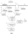
- FIG. 1 A simplified schematic block diagram of an exemplary autonomous situational awareness system, such as an intrusion detection system (IDS) according to an embodiment is illustrated in Fig. 1 .
- the system comprises plurality of wireless sensor nodes or stations 1, 2, 3, 4, 5 and 6 (any number of sensor stations may be employed), which are also called wireless detector devices herein, optionally one or more bridges 8 and 9, and a back-end server or central network entity 7.
- a plurality of wireless detector devices 1-6 may be placed in close proximity and around the monitored asset, object, area or perimeter 10 (in various places or following a certain installation pattern). Detector devices may be placed in selected locations manually or from vehicles, including deployment from aerial and water vehicles.
- the detector devices 1-6 may be configured to form a network of detector devices, and to exchange configuration information about the network and measurement information on the monitored environment acquired by detector devices.
- the detector devices 1-6 may be configured (programmed) to organize themselves into a wireless network of detector devices, such as an ad hoc network, that employs decentralized control, meaning that there may not be any requirement for a central control centre.
- An "ad hoc network” is a collection of wireless detector devices that can dynamically be set up anywhere and anytime without using any pre-existing network infrastructure.
- a structure of an ad hoc network is not fixed but can change dynamically, i.e. detector devices (nodes) 1-6 can be added to or removed from the ad hoc network while the ad hoc network is operational, without causing irreversible failures.
- an ad hoc network is able to reconfigure the flow of network traffic according to the current situation.
- a network of detector devices may use multi-hop networking wherein two or more wireless hops can be used to convey information from a detector device to an access network, and vice versa. In other words, a detector device may have a first wireless hop to a neighbouring detector device that may have a second wireless hop to a wireless bridge or to an access network.
- a wireless detector device may be an autonomous sensing device comprising at least one sensor for movement detection, and a wireless (preferably radio) communications interface unit, data processing capability, an autonomous power source and at least one digital camera.
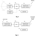
- a simplified schematic diagram of an exemplary wireless detector device is illustrated in Fig. 2 .
- a detector device 1 may be provided with a wireless communication interface 22, e.g. radio part with a transmitter, a receiver, and an antenna, a data processing unit 23, and an autonomous power supply 21, such as a battery.
- the autonomous power supply 21 may also be equipped with an energy harvesting device that enables collecting energy from the environment, for example a solar panel.
- the detector device 1 may comprise one or more sensors 24 for registering or measuring physical parameters related to movement (such as sound, light, seismic, vibration, magnetic field, infrared) and/or detecting changes in the environment (such as humidity, temperature, etc.).
- the detector device may be equipped with at least one passive infrared sensor (PIR) for the movement detection.
- the detector device may be equipped with at least one digital camera unit 23 for visual surveillance of the monitored asset, object, area or perimeter 10.
- the at least one digital camera unit 23 may include at least one day-time and/or at least one night-vision digital camera, for example a digital camera having an infrared capability to operate at night.
- a detector device 1 may be equipped with a high resolution digital camera for daytime surveillance and an infrared digital camera for night time security.
- the data processing unit 25 may comprise a microcontroller unit MCU which may include a processor part and a memory part as well as peripheral entities.
- the detector device 1 may also be equipped with a positioning hardware (for example a GPS receiver) providing location information (such as geographical coordinates).
- the wireless (preferably radio) communications interface unit 22 may be configured for a two-way wireless communication between wireless detector devices 1-6, between a wireless detector device 1-6 and a wireless bridge 8-9, and/or between a wireless detector device 1-6 and a wireless network access point 13.
- the wireless communications interface unit 22 may be equipped with a radio part with a transceiver (a transmitter and a receiver) and an antenna.
- a radio interface between detector devices 1-6 and a bridge 8- 9 may be configured for a short range radio communication, while a radio interface between the bridge 8-9 and a wireless access network 13 may be configured for a long range radio communication.
- Wireless interfaces employed may be based on any radio interfaces, such as a radio technology and protocols used in wireless local area networks (WLANs) or wireless personal area networks, such as IEEE 802.11 (WiFi), IEEE 802.15.1 (Bluetooth), IEEE 802.15.4 (ZigBee) technology, or in mobile communication systems, such as GSM and related "2G” and "2.5G” standards, including GPRS and EDGE; UMTS and related "3G” standards, including HSPA; LTE and related "4G” standards, including LTE Advanced and LTE Advanced Pro; Next generation and related "5G” standards; IS-95 (CDMA), commonly known as CDMA2000; TETRA, etc.
- a short range radio interface may be based on IEEE 802.15.4 (ZigBee) technology and a long range radio interface may be based on 3G or CDMA mobile communication technology.
- a wireless bridge 8 or 9 may be an autonomous wireless communication device equipped to communicate with the wireless detector devices 1-6 and a wireless access network, more specifically with a network access point 13 in the access network.
- a primary function of a wireless bridge 8-9 may forward alarm data and messages between wireless detector devices 1-6 and a wireless access network, and the back-end server or network entity 7.
- at least one bridge may communicate wirelessly directly with the back-end server or network entity 7, i.e. not via a wireless access network.
- the wireless bridge 9 is configured to have separate wireless one-hop connections to detector devices 1, 2 and 3, and a wireless one-hop connection to the network access point 13.
- the bridge 8 is configured to have separate wireless one-hop connections to the detectors 4 and 6, and a wireless multi-hop connection to the detector 5 via the detector 6, and a wireless one-hop connection to the network access point 13.
- a simplified schematic block diagram of an exemplary wireless bridge is illustrated in Fig. 3 .
- a wireless bridge may be provided with a wireless communication interface 32, e.g.
- a radio part with a transmitter, a receiver, and an antenna a data processing unit 33, such as a microcontroller unit MCU (which may include a processor part and a memory part as well as peripheral entities), a further wireless communication interface 34, and an autonomous power supply 31, such as a battery.
- a first wireless (preferably radio) communications interface unit 32 may be a short range wireless transceiver unit configured for a two-way wireless communication between wireless detector devices and the wireless bridge.
- a second wireless (preferably radio) communications interface unit 34 may be a long range wireless transceiver unit configured for a two-way long-range wireless communication between the wireless bridge and a wireless network access point.
- a back-end server or central network entity 7 may collect and store information from the wireless bridges 8-9 and the wireless detectors 1-6, and optionally from other sources, such as seismic sensors.
- the back-end server may be implemented by a server software stored and executed in suitable server computer hardware.
- a back-end server or central network entity 7 may be provided with a user interface (UI) 15, for example a graphical user interface, for alarm management and data analytics. For example, visual alarm information may be displayed either as an alarm flow or on geographical map.
- the user interface (UI) 15 may be a local UI at the location of the back-end server or network entity, or a remote UI communicatively connected to the back-end server or network entity.
- the back-end server or network entity 7 may be implemented in a workstation or laptop computer, and the UI15 comprises a monitor or display of the workstation or laptop.
- the back-end server or network entity 7 may be provided with an UI 15 in form of a web UI server which can be accessed by a web browser.
- the back-end server or network entity may also be equipped with a database, memory hardware or any type of digital data storage.
- the back-end server or network entity may further comprise various components for processing alarm events, analysing alarm events, detecting actors, classifying alarm events, filtering alarm events, and/or removing false alarms.
- such components may include one or more of an Actor Detector component, a Prefilter component, and a Detector Sensitivity Configurator component whose functionality will be described in more detail below.
- the processing unit MCU 25 may be configured (programmed) to monitor the outside physical world by acquiring samples the sensor(s) 24.
- the sensor 24 may trigger an event when an appropriate object is in its monitoring area. False triggers happen due to natural phenomena and low processing power.
- a passive infrared sensor may be used for human detection. Humans emit some amount of infrared radiation which is absorbed by the PIR sensor 24 to identify the human intrusion.
- the PIR sensor may be equipped with optics so that multiple detection zones may be arranged for each PIR sensor 24.
- the detector device 1 may also be equipped with an analog part that interfaces with the PIR sensor(s) and amplifies the PIR sensor signal according to environmental conditions.
- the analog part may comprise a separate analog path with configurable or adaptive signal amplification for each PIR sensor 24 (step 41 in Figure 4 ).
- the PIR sensor signal may be sampled by the MCU 25 in regular intervals (step 42). Information about date and/or time may be added to every piece of information.
- the MCU may be configured (programmed) to provide a digital front-end module, i.e. signal analysis and movement detection software. All the different PIR signals may be fed into the front-end module that may determine whether the PIR signal represents a movement or not.
- the determination may include measurement of one or more statistical parameters of the PIR signal (step 43) and comparing the measured parameter to current or historical parameter values (step 44), and deciding (step 45) that the PIR signal represents a movement if the comparison meets a predetermined criterion. If the PIR signal does not represent a movement (result "NO" from step 45), the front-end module may proceed to continue sampling in step 42.
- the front end module may optionally further try to determine one or more of a speed of the movement (step 46), a direction of the movement (step 47) and a distance of the object from the detector device 1 (step 48) before raising an alarm, called a device event herein, and/or triggering an event in the digital camera 23 (step 49).
- a sample of raw sensor data or readings for a configurable time window prior to the trigger time maybe stored locally in a memory of the detector device 1.
- the raw sensor data or readings may be stored into a buffer memory of a preconfigured size.
- the raw sensor data or readings may be stored in a ring buffer of a preconfigured size.
- stored raw data contents may also be associated with rolling-statistics for the raw samples included, such as rolling averages and/or floors over time.
- the stored raw data contents, and optionally the associated data may be sent to the server along with an event notification or alarm.
- FIG. 5 shows a simplified flow diagram illustrating an example of processing of a triggered camera event in a detector device 1.
- an event in the digital camera(s) 23 may be triggered by a movement detection or alarm made based on the sensor signal(s) (step 51 in Figure 5 ).
- the triggering sensor(s) 24 may be any suitable type of sensor or combination of different types of sensors, such as a PIR sensor, a seismic sensor, a magnetic sensor etc.
- the digital camera 23 may be triggered based on an alarm or triggering signal provided according to sensor detection embodiments described above with reference to Figure 3 .
- the triggered digital camera 23 may take or create one photographic image or two or more consecutive photographic images of the monitored asset, object, area or perimeter 10 (step 52).
- the digital camera 23 may create a configurable or predetermined number of images of the area in front of the digital camera in succession over a configurable or predetermined amount of time. All images the digital camera creates may have both a thumbnail image and a full resolution image available. Information about date and/or time and/or geographical position may be added to all images.
- a full resolution image refers to a full-size image or video frame with a normal or original resolution.
- a thumbnail image is a reduced-size or reduced resolution version of a full-size image or video frame.
- the collected set of created images are stored in a local memory in the detector device 1.
- a wireless detector device 1 may send an alarm notification to the back-end network entity or server 7 after every triggered camera event, without attempting to detect false alarms.
- the alarm notification may be sent with one or more thumbnail images of the triggered event, and optionally raw sensor data samples stored in a buffer memory, to the back-end network entity or server 7 for further processing and false alarm filtering.
- the back-end network entity or server 7 may request further thumbnail images or full images, if it has determined that the triggered event is a true alarm based on the already sent thumbnail image(s). Sending thumbnail images first may reduce the amount of data transferred and thereby may conserve the battery 21 of the detector device 1.
- a wireless detector device 1 may be configured to first perform a false alarm test for a triggered camera event, and to send an alarm notification to the back-end network entity or server 7 if the triggered camera event passes the false alarm test.
- a wireless detector device 1 may be configured to subject the triggered camera events to a strict and robust test to detect the easiest cases of false alarms. This may primarily mean that only cases where almost nothing moved or changed in the images will be classified as false alarms. Such a strict and robust test will require less processing power but will in any case reduce the number of false alarms sent to the back-end network entity or server 7, which both may conserve the battery 21 of the detector device 1.
- An alarm notification sent to the to the back-end network entity or server 7 may include information created during the false alarm test, and/or one or more thumbnail images, and optionally raw sensor data samples stored in a buffer memory.
- the MCU may be configured (programmed) to provide a digital front-end module, i.e. signal analysis and movement detection software.
- the front end module may create structural similarity indexes over a set of thumbnail images or full-size images subdivided into a number of subblocks of a preset size.
- the front-end module may create a subsampled change-sensitive hash from the image by means of a suitable hashing function or algorithm (step 53).
- a subsampled hash may describe the image only robustly.
- a suitable hash function may be a function that will create a similar (or even identical) hash for similar images from various features of the image content.
- a perceptual hashing function may be used.
- the created hash may be represented as a 2-dimensional matrix where every matrix cell may represent and robustly describe a corresponding sub block or sub-image in the original image. More specifically, each cell in the hash matrix may represent a measured value of at least one descriptive property of the respective subblock in the original image. Examples of such descriptive properties include luminance, color, and texture.
- the created hashes of the collected set of created images maybe stored locally in a memory of the detector device 1.
- the front-end may then subject the created hashes to a strict and robust test to detect the easiest cases of false alarms.
- the robust test to detect false alarms may comprise taking (computing) Hamming or Euclidean Distances (or similar) over hashes for all subset pairs of images in the current collected set of images (step 54).
- This may comprise computing Hamming or Euclidean Distance of every point or cell in the current hash to all provided previous hashes in the collected set of images, aggregating Hamming or Euclidean Distances of the same point or cell in the current hash into a two-dimensional distance matrix for the current image, and aggregating Hamming or Euclidean Distance matrix into an aggregated distance matrix in a way that enables to find high-variation hotspots in the distance matrix (step 55).
- the test may further comprise checking if any of the aggregated distance matrixes contains a relatively large continuous area of change (step 56). If a sufficient variance is determined in any of the aggregated distance maps of the subset pairs of images (result "YES" from step 56), the MCU 25 may send an alarm notification with the hashes, and optionally raw sensor data samples stored in a buffer memory, to the server 7 for further processing, and the processing of the triggered camera event at the detector device ends (steps 57 and 59). If the distance maps are relatively stable and do not contain any difference hotspots (result "NO” from step 56), then the alarm may be dismissed or dropped (step 58) and the processing of the triggered camera event at the detector device ends without no further action (step 59).
- FIG 6 shows a simplified schematic signalling diagram that illustrates an exemplary signalling and processing of an alarm.
- a movement is detected in a wireless detector device 1 and an alarm notification 61 is sent. There may a false alarm test before sending the alarm notification, for example as explained regarding step 58 in Figure 5 .
- the alarm notification 61 may be relayed to the back-end network entity or server 7 by the wireless bridge 8.
- the back-end server 7 may receive the alarm notification including information about the event, such as the image hashes and optionally raw sensor data samples.
- the back-end server may notify a user about the new event through a user interface (UI) 15 (step 62).
- UI user interface
- the back-end network entity or server 7 may perform a prefiltering of the current event by performing a false alarm analysis for event information, such as hashes and/or thumbnail images and optionally the raw sensor data samples, received in the current event and in at least one previous event to determine a resolution.
- the prefiltering analysis is generally illustrated as a Prefilter 65 in Figure 6 .
- the prefiltering 65 at the back-end server 7 may classify the current event as a false alarm or a true alarm based on the analysis.
- the robust and early prefiltering 65 enables to save on energy, radio bandwidth and processing power of the wireless detector device 1, because the detector device will not send full images or images at all for some false-alarm cases.
- the back-end server 7 may request one or more images in thumbnail and/or full resolution formats for more detailed analysis.
- the back-end server 7 may first send a request to send thumbnails 63A to the wireless detector device 1, and the wireless detector device 1 may reply by sending one or more thumbnails 63B to the back-end server 7.
- back-end server 7 may send a request to send full images 64A to the wireless detector device 1, and the wireless detector device 1 may reply by sending one or more full images 64B to the back-end server 7.
- a resolution reached by the actor detector 66 may be notified 67 to an end user through the user interface (UI) 15.
- UI user interface
- the end user may be notified that the alarm related to the new event 62 is dismissed (false alarm), still pending (further analysis needed) or a true alarm.
- the notification 67 may include at least one image relating to the alarm, and optionally more detailed information of the detected event, such as a location, size, speed, movement direction and/or class of an object or objects in the image.
- a resolution result may further be used to configure wireless detector devices for better detection in following triggers, as illustrated generally by a Sensitivity Configurator 68 in Figure 6 . Examples of the prefiltering 65, the actor detection 66, and the sensitivity configuration 68 will be given below.
- Figure 7 shows a flow diagram illustrating schematically a prefilter process 65 based on a hash analysis according an exemplary embodiment, as well as a further analysis or Actor detection 66 of a true alarm according to an exemplary embodiment.
- An alarm notification 61 with a set of hashes is received from a wireless detector 1 (step 71).
- the process may then look up hashes of previous events from the same detector device 1 which are locally stored in the back-end network entity or server. If sequentially previous events are relatively old, lighting or other visual condition changes at the surroundings of the detector device 1 may account for a large part of change between the images and hashes of the previous and current events.
- the prefilter process may optionally choose an event from an earlier time that likely had similar lightning or other visual conditions, e.g. an event from the previous day at roughly the same time.
- the prefilter process may optionally or additionally use robust difference metrics to find and choose the events with the most subjectively visually similar images from the database of past events in the back-end server. Then the prefilter process may load the hashes of the chosen previous set of events and calculate Hamming/Euclidean distances between all possible pairs of hashes of the current event and hashes of all chosen previous sets of events (step 72).
- Hamming/Euclidean distances may be calculated for all hash pairs in the exact same coordinates or immediate vicinity.
- Hamming or Euclidean Distances of the hash pairs may be aggregated in a way that enables to find high-variation hotspots in a distance matrix.
- the prefilter process may check whether there are high-variation hotspots among the aggregated Hamming or Euclidean distances of the hash pair (step 73). For example, in an embodiment, the prefilter process may check whether all hashes from the newest received set of hashes have a partner hash from a previous set of hashes with which some measured aggregated score meets a predetermined criterion, e.g.
- the aggregated score is below a threshold, it may be determined that no high-variation hotspot is found, and otherwise it is determined that a high-variation hotspot is found. If no hotspot is found (result "NO” from step 73), then the current event may be marked as a false-alarm (step 74) and the prefilter process may stop (step 75). If at least one hotspot is found (result "YES” from step 73), the current event may be determined to be a true-alarm. In case of a true-alarm, the prefilter process may request thumbnails and full images of the current event from the detector device 1 for further processing by other modules. This robust/early analysis enables to save on energy, bandwidth and processing power of the digital camera by not sending images at all for some false-alarm cases.
- the true-alarm from step 73 in Prefilter 65 may be subjected to more detailed analysis, or an Actor detection 66.
- a set of thumbnails may be first requested from the detector device 1 in steps 76A and 76B, and then a set of full images may be requested from the detector device 1 in steps 77A and 77B.
- both thumbnails and full images may be subjected to the same analysis 78 for resolution 79.
- the set of thumbnails may be analysed first and then the set of full images.
- the set of thumbnails received in steps 76B may be analysed first in step 78, and the full set of full images received in step 77B may be analysed later in step 78.
- the thumbnail images and the full images may be requested and/or received from the detector device 1 in sequence.
- An intermediate resolution for the current event may be made after each received thumbnail image, or after receiving all thumbnail images, and/or after each received full image, or after receiving all full images in the current event. In the case the intermediate resolution is considered to be accurate enough for setting a final resolution in step 79, no further thumbnails or full images might be needed. The smaller number of images is transferred for reaching a resolution for an event, the less energy and battery capacity is consumed for the transmission.
- thumbnails are smaller in a data file size (in amount of data) than full images, and therefore the transmission of thumbnails only conserve the battery of the wireless detector device 1.
- the thumbnails contain less visual information for giving a resolution of the current event, and they may give an incorrect resolution in some more difficult cases.
- the full images are larger in data file size and consume more battery capacity in transmission, but they also contain more visual information and should give a more accurate resolution result.
- the back-end network entity or server may have stored all the previous raw samples of previous events and may have coupled the previous events with resolutions.
- the analysis 78 and 79 may look for similarities in the new samples to the previous samples of past confirmed and unconfirmed events, and use a found similarities to assist in classifying the new event as a false alarm or a true alarm.
- a trained machine learning model may be used to detect patterns in raw sensor samples and give accurate results.
- a prefiltering 65 of the events may be based on the set of thumbnails to detect and reject events with images where there is no (meaningful) change, i.e. false alarms.
- the back-end network entity or server 7 may not receive hashes with the alarm notification 61 but may receive 63B or request 63A one or more thumbnails for prefiltering 65.
- Figure 8 shows a simplified schematic signalling diagram that illustrates exemplary signalling and processing of an alarm according the other aspect of the invention. Upon classifying an event as a false alarm, the further prosecution of the event may be stopped.
- the more detailed analysis of the event may continue as in the further analysis or Actor Detector 66 in Figure 6 , except that requesting thumbnails can be omitted.
- the already received set of thumbnails may be subjected to further analysis, and a set of full images may be requested from the detector device 1 for further analysis.
- a structural similarity index may be associated with a thumbnail and a previous thumbnail, and a predetermined structural features may be associated with the similarity index.
- Figure 9 illustrates a matrix of structural similarity indexes calculated over n thumbnails.
- the thumbnail images may be subdivided into a number of subblocks with a preset or configurable grid size. Each cell in the matrix represents a subblock in the original image.
- the similarity indexes may be hashes that are calculated by a hash function, for example as described above for a false alarm test in the detector device 1. If the structural similarity indexes suggest a considerable movement of an object over the compared images, the event may be classified as a true alarm in the prefiltering 65.
- the event may be classified as a false alarm in the prefiltering.
- Further structural parameters such as one or more of shape, size, orientation, speed, location, etc., of an interesting object may be taken into account when considering whether there is a meaningful change or movement.
- a structural index pattern with a predetermined parameters e.g. size, shape
- a structural index pattern with another set of predetermined parameters may suggest a vehicle object, etc.
- An exemplary similarity index matrix is schematically illustrated in Figure 9 .
- a grey scale of the sublocks or cells may represent a degree of the similarity: white colour represents “no difference”, light grey colour represents “small difference”, dark grey colour represents “medium difference”, and black colour represents "big difference” between the corresponding subblocks of the compared images.
- Neighbouring subblocks with grey or black colour may form a larger continuous pattern which facilitates to detect a true alarm.
- the larger pattern may also have a shape and/or size which is characteristic to an interesting object, such as human or vehicle, which may further verify that the current event is a true alarm. Upon classifying an event as a false alarm, the further prosecution of the event may be stopped.
- the more detailed analysis of the event may continue as illustrated in section 66 in Figure 7 , except that steps 76A and 76B for obtaining thumbnails can be omitted.
- the already received set of thumbnails may be subjected to further analysis in step 78, and a set of full images may be requested (steps 77A and 77B) from the detector device 1 for further analysis in Figure 7 .
- the actor detector 66 may be any type of a more detailed analysis of the event for detecting change in an image and for classifying objects from the information in the image.
- the classification may be based on size, position and/or confidence of an object, and an object may be classified into object classes, such as human, car, truck, tree, bush, etc.
- object classes may be marked as "interesting", e.g. humans, vehicles, animals.
- the "interesting" object classes may be used for positive detection and marking events as true alarms. For example, if an object of the interesting object class moves in the image.
- Other object classes like trees and bushes may be used as reference points and background detection.
- All object classes may be robustly described with physical features, such as an average size, an average width and/or an average height of the object.
- every detected object may be given a probable distance from the digital camera and all the distances may be correlated with each other by taking into account the vertical position in the image. For example, if a tree and a person are in the same vertical position in the image, it is possible to calculate the probable distance of the person by using the known average dimensions of people and trees.
- An output from the actor detector may be an alarm with classification of objects, or notification that the event is false alarm, or some other notification 67 that may be useful.
- a further analysis of the set of thumbnails and the set of full images may comprise a movement filter.
- the movement filter may be based on structural features and an optical flow over current and chosen previous images.
- the movement filter may use visual information in the images and compare them to discover considerable movement in large areas.
- the visual information or structural features may include SURF (Speeded Up Robust Features) features, such as isolated points, lines, edges, corners, or other regions of high variance.
- Optical flow is a pattern of an apparent motion of image objects between two consecutive images caused by the movement of an object, or more generally the optical flow is the apparent motion of brightness patterns in the image.
- inputs to the motion filter may include a current image, and one or more previous images as a reference.
- SURF features or other structural features may be calculated for all the input images over a preset or configurable grid size.
- feature distances may be calculated for the current image against all the previous images inputted as a reference.
- the calculated feature distances may be aggregated into scores for every described point, i.e. every subblock or grid cell. This will give a one dimensional score for every subblock in the current image. If a score is below (or above) a dynamic or preconfigured threshold then the described area or subblock may be marked as "possible movement". Then Optical Flow maps may be calculated between the current image and all given previous images.
- Optical flow map may contain an Optical Flow Field for each described area or subblock.
- An optical flow field is a projection of onto the 2-dimensional digital image.
- the maps are aggregated into a single optical flow map.
- the aggregated optical flow map is overlaid onto the descriptor map. Any area that wasn't possible movement gets assigned as "possible movement”. Any area that already was “possibly movement” gets marked as "movement”. By combining these two methods the result is very accurate. If large consecutive areas are marked as a "movement” then a resolution of true-alarm is given , else false-alarm is given.
- Optical flows also allow it to calculate possible movement direction of the object.
- a back-end server or network entity 7 may be provided with a sensitivity configurator, as illustrated generally by a Sensitivity Configurator 68 in Figures 6 and 8 , which may utilize results from the prefiltering or actor detector to configure the sensitivity of wireless detector devices for better detection in following triggers.
- a detection sensitivity of the intrusion detector device may be configured less sensitive, if the number x of false alarms in a predetermined period of time y exceeds a preset threshold, for example by sending a Change detection parameters message as illustrated by message 69A in Figures 6 and 8 .
- a detection sensitivity of the intrusion detector device may be configured less sensitive, if percentage of false alarms of total number of alarms exceeds a preset threshold. In a further embodiment, a detection sensitivity of the intrusion detector device may be configured more sensitive, if no new events is received in a predetermined period, as illustrated by a message 69B in Figures 6 and 8 .
- the intrusion detector device 1 may reconfigure the detection sensitivity according to sensitivity parameters received from the intrusion detection network entity or server 7.
- Examples of possible sensitivity parameters may include an amplification of an analog sensor signal, a predetermined (configurable) criterion for detecting motion in a motion sensor and a criterion for detecting high-variation hotspots in an aggregated distance matrix, etc.
- Various technical means can be used for implementing functionality of a corresponding apparatus, such as detector device or a network entity or a server, described with embodiments and it may comprise separate means for each separate function, or means may be configured to perform two or more functions.
- Present apparatuses comprise processors and memory that can be utilized in an embodiment.
- functionality of an apparatus according to an embodiment may be implemented as a software application, or a module, or a unit configured as arithmetic operation, or as a program (including an added or updated software routine), executed by an operation processor.
- Programs, also called program products, including software routines, applets and macros can be stored in any apparatus-readable data storage medium and they include program instructions to perform particular tasks.
- routines may be implemented as added or updated software routines, application circuits (ASIC) and/or programmable circuits. Further, software routines may be downloaded into an apparatus.
- the apparatus such as a detector device or a back-end server or corresponding components and/or other corresponding devices or apparatuses described with an embodiment may be configured as a computer or a microprocessor, such as single-chip computer element, including at least a memory for providing storage area used for arithmetic operation and an operation processor for executing the arithmetic operation.
- An example of the operation processor includes a central processing unit.
- the memory may be removable memory detachably connected to the apparatus.
- an apparatus may be implemented in hardware (one or more apparatuses), firmware (one or more apparatuses), software (one or more modules), or combinations thereof.
- firmware or software implementation can be through modules (e.g., procedures, functions, and so on) that perform the functions described herein.
- the software codes may be stored in any suitable, processor/computer-readable data storage medium(s) or memory unit(s) or article(s) of manufacture and executed by one or more processors/computers.
- the data storage medium or the memory unit may be implemented within the processor/computer or external to the processor/computer, in which case it can be communicatively coupled to the processor/computer via various means as is known in the art.
Landscapes
- Physics & Mathematics (AREA)
- General Physics & Mathematics (AREA)
- Engineering & Computer Science (AREA)
- Multimedia (AREA)
- Business, Economics & Management (AREA)
- Emergency Management (AREA)
- Library & Information Science (AREA)
- Alarm Systems (AREA)
Claims (15)
- Eindringdetektionsverfahren, das in einer autonomen drahtlosen Detektorvorrichtung (1, 2, 3, 4, 5, 6) umgesetzt wird, die mindestens einen Bewegungssensor (24) und mindestens eine digitale Kamera (23) umfasst, das Folgendes umfasstAuslösen (51) eines neuen Alarmereignisses in Reaktion darauf, dass der Bewegungssensor (24) eine potenzielle Bewegung in einem überwachten Bereich detektiert,Auslösen der digitalen Kamera (23) zum Erstellen (52) eines Satzes von aufeinanderfolgenden Bildern voller Größe des überwachten Bereichs für das neue Alarmereignis,Erstellen (52) eines Satzes von Miniaturbildern reduzierter Größe, der dem Satz von digitalen Bildern voller Größe des neuen Alarmereignisses entspricht, für das neue Alarmereignis,Speichern (52) des Satzes von digitalen Bildern voller Größe und des Satzes von Miniaturbildern des neuen Alarmereignisses in der drahtlosen Detektorvorrichtung (1, 2, 3, 4, 5, 6),Senden (61, 62) einer Benachrichtigung über das neue Alarmereignis und von Ereignisinformationen, die sich auf die Bilder reduzierter Größe beziehen, an eine Eindringdetektionsnetzwerkentität (7), wobei die Ereignisinformationen über die Bilder reduzierter Größe Bildbeschreibungsinformationen beinhalten, die Hashes umfassen, die auf Basis des Satzes von Miniaturbildern oder des Satzes von digitalen Bildern voller Größe berechnet (53) werden, undSenden (63B, 64B) des Satzes von Bildern voller Größe an die Eindringdetektionsnetzwerkentität (7) nur, wenn sie von der Eindringdetektionsnetzwerkentität (7) angefordert (63A, 64A) werden, nach dem Senden (61, 62) der Ereignisinformationen über die Bilder reduzierter Größe.
- Verfahren nach Anspruch 1, wobei die Bildbeschreibungsinformationen unterabgetastete änderungssensitive Hashes beinhalten, die auf Basis des Satzes von Miniaturbildern oder des Satzes von digitalen Bildern voller Größe berechnet werden; und die Ereignisinformationen wahlweise ferner eines oder mehreres von Folgendem beinhalten: Bewegungssensordaten, Datum, Zeit und geografische Position.
- Verfahren nach Anspruch 1 oder 2, das ferner Folgendes umfasstSenden (63B) des Satzes von Miniaturbildern an die Eindringdetektionsnetzwerkentität (7) nur, wenn sie von der Eindringdetektionsnetzwerkentität angefordert (63A) werden, nach dem Senden (61, 62) der Benachrichtigung über das neue Alarmereignis und der Ereignisinformationen über die Bilder reduzierter Größe, undSenden (64B) des Satzes von Bildern voller Größe an die Eindringdetektionsnetzwerkentität (7) nur, wenn sie vom Eindringdetektionsserver angefordert (64A) werden, nach dem Senden des Satzes von Miniaturbildern.
- Verfahren nach einem der Ansprüche 1 bis 3, das Folgendes umfasstDurchführen (53, 54, 55, 56, 58, 59) eines robusten Fehlalarmtests für das neue Alarmereignis,Senden (57, 61, 62) der Benachrichtigung über das neue Alarmereignis und von Ereignisinformationen über die Bilder reduzierter Größe an die Eindringdetektionsnetzwerkentität (7), wenn das neue Alarmereignis gemäß dem Fehlalarmtest ein wirklicher Alarm ist (56), und andernfalls Beenden (58, 59) des neuen Alarmereignisses als einen Fehlalarm.
- Verfahren nach Anspruch 4, wobei der Fehlalarmtest Folgendes umfasstAnalysieren einer Ähnlichkeit von mindestens einem Miniaturbild oder einem Bild voller Größe des neuen Alarmereignisses mit mindestens einem vorherigen Miniaturbild oder Bild voller Größe des neuen Alarmereignisses oder eines vorherigen Alarmereignisses,Beenden des neuen Alarmereignisses als einen Fehlalarm, wenn sich die Bilder ähnlich oder fast ähnlich sind, undSenden der Benachrichtigung über das neue Alarmereignis und der Ereignisinformationen über die Bilder reduzierter Größe an die Eindringdetektionsnetzwerkentität, wenn sich die Bilder nicht fast ähnlich sind.
- Verfahren nach Anspruch 4 oder 5, wobei der Fehlalarmtest Folgendes umfasstErstellen (53) von unterabgetasteten Hashes anhand des mindestens einen Miniaturbildes oder eines Bildes voller Größe des neuen Alarmereignisses und anhand mindestens eines vorherigen Miniaturbildes oder Bildes voller Größe des neuen Alarmereignisses oder eines vorherigen Alarmereignisses,Berechnen (54, 55) von aggregierten Hamming- oder euklidischen oder entsprechenden Abständen über Hashes für alle unterabgetasteten änderungssensitiven Hashes,wenn die aggregierten Abstände einen Punkt einer Hochvariationsdifferenz zwischen dem mindestens einen neuen Miniaturbild oder Bild voller Größe und dem mindestens vorherigen Miniaturbild oder Bild voller Größe anzeigen, Einstellen (56, 57) des neuen Alarms als einen wirklichen Alarm und andernfalls Einstellen (56, 58, 59) des neuen Alarms als einen Fehlalarm.
- Verfahren nach einem der Ansprüche 1 bis 6, das das Neuauslegen einer Detektionsempfindlichkeit der Eindringdetektorvorrichtung gemäß Empfindlichkeitsparametern umfasst, die von der Eindringdetektornetzwerkentität (7) empfangen werden (69A, 69B).
- Eindringdetektionsverfahren, das in einem System umgesetzt wird, das eine Eindringdetektornetzwerkentität (7) und eine autonome drahtlose Detektorvorrichtung (1, 2, 3, 4, 5, 6) umfasst, wobei das Verfahren Folgendes umfasstEmpfangen (61, 62) einer Benachrichtigung über ein neues Ereignis und von Ereignisinformationen über Bilder reduzierter Größe von der autonomen drahtlosen Detektorvorrichtung, wobei die Detektorvorrichtung gemäß einem Verfahren nach einem der Ansprüche 1 bis 7 betrieben wird,Vorfiltern (65) des neuen Ereignisses auf Basis der empfangenen Ereignisinformationen über Bilder reduzierter Größe,Beenden (75) eines Verarbeitens des neuen Ereignisses, wenn das Vorfiltern zu einer Beurteilung (73, 74) führt, dass der neue Alarm auf Basis der empfangenen Ereignisinformationen über Bilder reduzierter Größe ein Fehlalarm ist, undFortsetzen des Verarbeitens des neuen Ereignisses, wenn das Vorfiltern (65) zu einer Beurteilung (73, 76A) führt, dass der neue Alarm auf Basis der empfangenen Ereignisinformationen über Bilder reduzierter Größe ein wirklicher Alarm ist, wobei das Fortsetzen das Anfordern (63A, 63B, 76A, 76B, 77A, 77B) von Miniaturbildern reduzierter Größe und/oder von digitalen Bildern voller Größe von der Eindringdetektorvorrichtung für eine weitere Ereignisanalyse beinhaltet.
- Verfahren nach Anspruch 8, wobei die empfangenen Informationen über Bilder reduzierter Größe unterabgetastete änderungssensitive Hashes umfassen, die von der Eindringdetektorvorrichtung anhand von mindestens einem Miniaturbild oder einem Bild voller Größe des neuen Alarmereignisses und anhand von mindestens einem vorherigen Miniaturbild oder einem Bild voller Größe des neuen Alarmereignisses oder eines vorherigen Alarmereignisses erstellt werden und wobei das Vorfiltern (65) Folgendes umfasstAbrufen von Hashes von mindestens einem vorherigen Ereignis derselben Eindringdetektorvorrichtung aus einer Datenbank der Eindringdetektornetzwerkentität,Berechnen (72) von Hamming- oder euklidischen oder entsprechenden Abständen zwischen Paaren von Hashes des neuen Ereignisses und Hashes des mindestens einen vorherigen Ereignisses,Aggregieren der berechneten Abstände der Hashpaare,Prüfen (73), ob jeder der empfangenen Hashes des neuen Ereignisses unter den Hashes des mindestens einen vorherigen Alarmereignisses einen Partnerhash aufweist, mit dem eine gemessene aggregierte Bewertung ein vorbestimmtes Kriterium erfüllt,wenn jeder der empfangenen Hashes das vorbestimmte Kriterium erfüllt, führt das Vorfiltern zu einer Beurteilung (73, 74), dass der neue Alarm ein Fehlalarm ist, und andernfalls führt das Vorfiltern zu einer Beurteilung (73, 76A), dass der neue Alarm ein wirklicher Alarm ist, undwobei das Fortsetzen des Verarbeitens das Anfordern (63A, 63B, 76A, 76B, 77A, 77B) von Miniaturbildern reduzierter Größe und/oder von digitalen Bildern voller Größe von der Eindringdetektorvorrichtung umfasst.
- Verfahren nach Anspruch 8, wobei die empfangenen Informationen über Bilder reduzierter Größe ein oder mehrere Miniaturbilder reduzierter Größe des neuen Ereignisses umfassen und wobei das Vorfiltern Folgendes umfasstBerechnen von strukturellen Ähnlichkeitsindices über einen Satz von Miniaturbildern, der in eine Anzahl von Unterblöcken einer voreingestellten Gittergröße unterteilt ist,wenn der Ähnlichkeitsindex eines einzelnen Unterblocks ein vorbestimmtes Kriterium erfüllt oder Ähnlichkeitsindices eines Satzes von Unterblöcken, die ein Muster einer voreingestellten Größe oder Form darstellen, ein vorbestimmtes Kriterium erfüllen, wird eine Bewegung eines Objekts detektiert und das Vorfiltern führt zu einer Beurteilung, dass das neue Ereignis ein wirkliches Ereignis ist, und andernfalls führt das Vorfiltern zu einer Beurteilung, dass das neue Ereignis ein falsches Ereignis ist, und wobei das Fortsetzen des Verarbeitens des neuen Ereignisses das Anfordern (77A, 77B) der Bilder voller Größe nur umfasst, nachdem das Verarbeiten oder Vorfiltern der Miniaturbilder reduzierter Größe zu einer Beurteilung führt, dass das neue Ereignis ein wirklicher Alarm ist.
- Verfahren nach einem der Ansprüche 8 bis 10, wobei die Fortsetzung des Verarbeitens des neuen Ereignisses das Bestimmen einer Klasse eines in den Bildern detektierten Objekts, einer Bewegungsgeschwindigkeit des Objekts und/oder einer Bewegungsrichtung des Objekts umfasst.
- Verfahren nach einem der Ansprüche 8 bis 11, das das Bereitstellen von einem oder mehrerem von Folgendem für einen Endbenutzer über eine Benutzerschnittstelle umfasst: einer Benachrichtigung über das Empfangen des neuen Alarmereignisses; einer Benachrichtigung über einen Fehlalarm; einer Benachrichtigung über einen wirklichen Alarm; einem oder mehreren Miniaturbildern oder Bildern voller Größe des neuen Alarmereignisses; einer Klasse eines detektierten Objekts; einer Bewegungsgeschwindigkeit; einer Bewegungsrichtung.
- Verfahren nach einem der Ansprüche 8 bis 12, das das Steuern (68) einer Detektionsempfindlichkeit der Eindringdetektorvorrichtung auf weniger empfindlich oder empfindlicher auf Basis der Falsch-Wahr-Klassifizierung des empfangenen Alarmereignisses umfasst.
- Autonome drahtlose Detektorvorrichtung, die mindestens einen Bewegungssensor für eine Bewegungsdetektion, eine drahtlose Kommunikationsschnittstelleneinheit, eine Datenverarbeitungseinheit, eine autonome Energiequelle und mindestens eine digitale Kamera umfasst, wobei die autonome drahtlose Detektorvorrichtung dazu ausgelegt ist, das Verfahren nach einem der Ansprüche 1 bis 7 zu implementieren.
- System, das eine Eindringdetektornetzwerkentität und die autonome drahtlose Detektorvorrichtung von Anspruch 14 umfasst, wobei die Entität eine Datenverarbeitungseinheit und eine zugehörige Benutzerschnittstelle umfasst, wobei das System dazu ausgelegt ist, das Verfahren nach einem der Ansprüche 8 bis 13 auszuführen.
Applications Claiming Priority (2)
| Application Number | Priority Date | Filing Date | Title |
|---|---|---|---|
| FI20175933 | 2017-10-20 | ||
| PCT/EP2018/078342 WO2019076951A1 (en) | 2017-10-20 | 2018-10-17 | METHODS AND DEVICES FOR INTRUSION DETECTION |
Publications (3)
| Publication Number | Publication Date |
|---|---|
| EP3698336A1 EP3698336A1 (de) | 2020-08-26 |
| EP3698336C0 EP3698336C0 (de) | 2024-09-18 |
| EP3698336B1 true EP3698336B1 (de) | 2024-09-18 |
Family
ID=63896181
Family Applications (1)
| Application Number | Title | Priority Date | Filing Date |
|---|---|---|---|
| EP18789116.3A Active EP3698336B1 (de) | 2017-10-20 | 2018-10-17 | Verfahren und vorrichtungen zur eindringdetektion |
Country Status (3)
| Country | Link |
|---|---|
| US (2) | US11120676B2 (de) |
| EP (1) | EP3698336B1 (de) |
| WO (1) | WO2019076951A1 (de) |
Families Citing this family (6)
| Publication number | Priority date | Publication date | Assignee | Title |
|---|---|---|---|---|
| US11120676B2 (en) | 2017-10-20 | 2021-09-14 | Thinnect OÜ | Intrusion detection methods and devices |
| US10996325B2 (en) * | 2018-11-30 | 2021-05-04 | Ademco Inc. | Systems and methods for adjusting a signal broadcast pattern of an intrusion detector |
| US10762773B1 (en) | 2019-08-19 | 2020-09-01 | Ademco Inc. | Systems and methods for building and using a false alarm predicting model to determine whether to alert a user and/or relevant authorities about an alarm signal from a security system |
| CN111555917A (zh) * | 2020-04-26 | 2020-08-18 | 四川爱创科技有限公司 | 基于云平台的告警信息处理方法及装置 |
| US12457213B2 (en) * | 2022-11-16 | 2025-10-28 | Oracle International Corporation | Secure reuse of cloud at customer hardware |
| US20260051169A1 (en) * | 2024-08-19 | 2026-02-19 | Tyco Fire & Security Gmbh | Methods and apparatuses for operating a surveillance system with reduced impact |
Family Cites Families (12)
| Publication number | Priority date | Publication date | Assignee | Title |
|---|---|---|---|---|
| US5937092A (en) | 1996-12-23 | 1999-08-10 | Esco Electronics | Rejection of light intrusion false alarms in a video security system |
| US6628835B1 (en) * | 1998-08-31 | 2003-09-30 | Texas Instruments Incorporated | Method and system for defining and recognizing complex events in a video sequence |
| IL127407A (en) * | 1998-12-06 | 2004-07-25 | Electronics Line E L Ltd | Infrared intrusion detector and method |
| GB2363028B (en) | 2000-04-26 | 2002-06-12 | Geoffrey Stubbs | IRIS Intelligent Remote Intruder Surveillance |
| US20040080615A1 (en) * | 2002-08-21 | 2004-04-29 | Strategic Vista Intenational Inc. | Digital video security system |
| US9386281B2 (en) | 2009-10-02 | 2016-07-05 | Alarm.Com Incorporated | Image surveillance and reporting technology |
| US8626210B2 (en) * | 2010-11-15 | 2014-01-07 | At&T Intellectual Property I, L.P. | Methods, systems, and products for security systems |
| JP5962916B2 (ja) | 2012-11-14 | 2016-08-03 | パナソニックIpマネジメント株式会社 | 映像監視システム |
| US10075680B2 (en) * | 2013-06-27 | 2018-09-11 | Stmicroelectronics S.R.L. | Video-surveillance method, corresponding system, and computer program product |
| US20160078316A1 (en) | 2014-08-18 | 2016-03-17 | Aes Corporation | Simulated Human Cognition Sensor System |
| GB201508074D0 (en) * | 2015-05-12 | 2015-06-24 | Apical Ltd | People detection |
| US11120676B2 (en) | 2017-10-20 | 2021-09-14 | Thinnect OÜ | Intrusion detection methods and devices |
-
2018
- 2018-10-17 US US16/757,495 patent/US11120676B2/en active Active
- 2018-10-17 EP EP18789116.3A patent/EP3698336B1/de active Active
- 2018-10-17 WO PCT/EP2018/078342 patent/WO2019076951A1/en not_active Ceased
-
2021
- 2021-08-24 US US17/410,562 patent/US11935378B2/en active Active
Also Published As
| Publication number | Publication date |
|---|---|
| US11120676B2 (en) | 2021-09-14 |
| EP3698336C0 (de) | 2024-09-18 |
| EP3698336A1 (de) | 2020-08-26 |
| US20200250945A1 (en) | 2020-08-06 |
| WO2019076951A1 (en) | 2019-04-25 |
| US11935378B2 (en) | 2024-03-19 |
| US20210383664A1 (en) | 2021-12-09 |
Similar Documents
| Publication | Publication Date | Title |
|---|---|---|
| US11935378B2 (en) | Intrusion detection methods and devices | |
| WO2019076954A1 (en) | METHODS AND DEVICES FOR INTRUSION DETECTION | |
| US9396400B1 (en) | Computer-vision based security system using a depth camera | |
| CN101999888B (zh) | 一种对体温异常者进行检测与搜寻的疫情防控系统 | |
| CN104303193B (zh) | 基于聚类的目标分类 | |
| CN109484935A (zh) | 一种电梯轿厢监控方法、装置及系统 | |
| CN109543607A (zh) | 目标物异常状态检测方法、系统、监护系统及存储介质 | |
| US11325777B2 (en) | Systems and processes for space management of three dimensional containers including biological measurements | |
| CN110674753A (zh) | 偷盗行为预警方法、终端设备及存储介质 | |
| KR20220000172A (ko) | 엣지 컴퓨팅 기반 보안 감시 서비스 제공 장치, 시스템 및 그 동작 방법 | |
| KR20220000424A (ko) | 엣지 컴퓨팅 기반 지능형 보안 감시 카메라 시스템 | |
| US10922819B2 (en) | Method and apparatus for detecting deviation from a motion pattern in a video | |
| CN118918519B (zh) | 基于对象成像的桥梁健康状态检测预警方法及装置和介质 | |
| CN113965733A (zh) | 双目视频监控方法、系统、计算机设备及存储介质 | |
| JP2021007055A (ja) | 識別器学習装置、識別器学習方法およびコンピュータプログラム | |
| KR20210001318A (ko) | 지능형 감시 시스템, 방법, 및 상기 방법을 실행시키기 위한 컴퓨터 판독 가능한 프로그램을 기록한 기록 매체 | |
| CN118097192A (zh) | 一种基于云边协同的网关数据处理方法及系统 | |
| Ko et al. | On scaling distributed low-power wireless image sensors | |
| EP4191543B1 (de) | Bildverarbeitungssystem | |
| KR20240148503A (ko) | 원격소를 실시간으로 모니터링하고 제어하기 위한 농업용수 통합 관제망 통신시스템 | |
| Picus et al. | Novel smart sensor technology platform for border crossing surveillance within foldout | |
| Wang et al. | YOLOv8-Helmet: An Optimized Architecture for High-Performance Safety Helmet Detection in Complex Construction Environments | |
| Sofwan et al. | Design of smart open parking using background subtraction in the IoT architecture | |
| CN116668488B (zh) | 一种设备配置方法、装置、电子设备及存储介质 | |
| KR20220000189A (ko) | 엣지 컴퓨팅 기반 지능형 보안 감시 서비스 제공 장치 |
Legal Events
| Date | Code | Title | Description |
|---|---|---|---|
| STAA | Information on the status of an ep patent application or granted ep patent |
Free format text: STATUS: UNKNOWN |
|
| STAA | Information on the status of an ep patent application or granted ep patent |
Free format text: STATUS: THE INTERNATIONAL PUBLICATION HAS BEEN MADE |
|
| PUAI | Public reference made under article 153(3) epc to a published international application that has entered the european phase |
Free format text: ORIGINAL CODE: 0009012 |
|
| STAA | Information on the status of an ep patent application or granted ep patent |
Free format text: STATUS: REQUEST FOR EXAMINATION WAS MADE |
|
| 17P | Request for examination filed |
Effective date: 20200520 |
|
| AK | Designated contracting states |
Kind code of ref document: A1 Designated state(s): AL AT BE BG CH CY CZ DE DK EE ES FI FR GB GR HR HU IE IS IT LI LT LU LV MC MK MT NL NO PL PT RO RS SE SI SK SM TR |
|
| AX | Request for extension of the european patent |
Extension state: BA ME |
|
| RAP1 | Party data changed (applicant data changed or rights of an application transferred) |
Owner name: THINNECT OUE |
|
| DAV | Request for validation of the european patent (deleted) | ||
| DAX | Request for extension of the european patent (deleted) | ||
| STAA | Information on the status of an ep patent application or granted ep patent |
Free format text: STATUS: EXAMINATION IS IN PROGRESS |
|
| 17Q | First examination report despatched |
Effective date: 20220809 |
|
| RAP1 | Party data changed (applicant data changed or rights of an application transferred) |
Owner name: DEFENDEC OUE |
|
| GRAP | Despatch of communication of intention to grant a patent |
Free format text: ORIGINAL CODE: EPIDOSNIGR1 |
|
| STAA | Information on the status of an ep patent application or granted ep patent |
Free format text: STATUS: GRANT OF PATENT IS INTENDED |
|
| INTG | Intention to grant announced |
Effective date: 20240417 |
|
| GRAS | Grant fee paid |
Free format text: ORIGINAL CODE: EPIDOSNIGR3 |
|
| GRAA | (expected) grant |
Free format text: ORIGINAL CODE: 0009210 |
|
| STAA | Information on the status of an ep patent application or granted ep patent |
Free format text: STATUS: THE PATENT HAS BEEN GRANTED |
|
| AK | Designated contracting states |
Kind code of ref document: B1 Designated state(s): AL AT BE BG CH CY CZ DE DK EE ES FI FR GB GR HR HU IE IS IT LI LT LU LV MC MK MT NL NO PL PT RO RS SE SI SK SM TR |
|
| REG | Reference to a national code |
Ref country code: GB Ref legal event code: FG4D |
|
| REG | Reference to a national code |
Ref country code: CH Ref legal event code: EP |
|
| REG | Reference to a national code |
Ref country code: IE Ref legal event code: FG4D |
|
| REG | Reference to a national code |
Ref country code: DE Ref legal event code: R096 Ref document number: 602018074526 Country of ref document: DE |
|
| U01 | Request for unitary effect filed |
Effective date: 20241015 |
|
| U07 | Unitary effect registered |
Designated state(s): AT BE BG DE DK EE FI FR IT LT LU LV MT NL PT RO SE SI Effective date: 20241030 |
|
| PG25 | Lapsed in a contracting state [announced via postgrant information from national office to epo] |
Ref country code: NO Free format text: LAPSE BECAUSE OF FAILURE TO SUBMIT A TRANSLATION OF THE DESCRIPTION OR TO PAY THE FEE WITHIN THE PRESCRIBED TIME-LIMIT Effective date: 20241218 |
|
| PG25 | Lapsed in a contracting state [announced via postgrant information from national office to epo] |
Ref country code: GR Free format text: LAPSE BECAUSE OF FAILURE TO SUBMIT A TRANSLATION OF THE DESCRIPTION OR TO PAY THE FEE WITHIN THE PRESCRIBED TIME-LIMIT Effective date: 20241219 |
|
| U20 | Renewal fee for the european patent with unitary effect paid |
Year of fee payment: 7 Effective date: 20241217 |
|
| PG25 | Lapsed in a contracting state [announced via postgrant information from national office to epo] |
Ref country code: HR Free format text: LAPSE BECAUSE OF FAILURE TO SUBMIT A TRANSLATION OF THE DESCRIPTION OR TO PAY THE FEE WITHIN THE PRESCRIBED TIME-LIMIT Effective date: 20240918 |
|
| PG25 | Lapsed in a contracting state [announced via postgrant information from national office to epo] |
Ref country code: RS Free format text: LAPSE BECAUSE OF FAILURE TO SUBMIT A TRANSLATION OF THE DESCRIPTION OR TO PAY THE FEE WITHIN THE PRESCRIBED TIME-LIMIT Effective date: 20241218 |
|
| PG25 | Lapsed in a contracting state [announced via postgrant information from national office to epo] |
Ref country code: RS Free format text: LAPSE BECAUSE OF FAILURE TO SUBMIT A TRANSLATION OF THE DESCRIPTION OR TO PAY THE FEE WITHIN THE PRESCRIBED TIME-LIMIT Effective date: 20241218 Ref country code: NO Free format text: LAPSE BECAUSE OF FAILURE TO SUBMIT A TRANSLATION OF THE DESCRIPTION OR TO PAY THE FEE WITHIN THE PRESCRIBED TIME-LIMIT Effective date: 20241218 Ref country code: HR Free format text: LAPSE BECAUSE OF FAILURE TO SUBMIT A TRANSLATION OF THE DESCRIPTION OR TO PAY THE FEE WITHIN THE PRESCRIBED TIME-LIMIT Effective date: 20240918 Ref country code: GR Free format text: LAPSE BECAUSE OF FAILURE TO SUBMIT A TRANSLATION OF THE DESCRIPTION OR TO PAY THE FEE WITHIN THE PRESCRIBED TIME-LIMIT Effective date: 20241219 |
|
| PG25 | Lapsed in a contracting state [announced via postgrant information from national office to epo] |
Ref country code: IS Free format text: LAPSE BECAUSE OF FAILURE TO SUBMIT A TRANSLATION OF THE DESCRIPTION OR TO PAY THE FEE WITHIN THE PRESCRIBED TIME-LIMIT Effective date: 20250118 |
|
| PG25 | Lapsed in a contracting state [announced via postgrant information from national office to epo] |
Ref country code: SM Free format text: LAPSE BECAUSE OF FAILURE TO SUBMIT A TRANSLATION OF THE DESCRIPTION OR TO PAY THE FEE WITHIN THE PRESCRIBED TIME-LIMIT Effective date: 20240918 |
|
| PG25 | Lapsed in a contracting state [announced via postgrant information from national office to epo] |
Ref country code: ES Free format text: LAPSE BECAUSE OF FAILURE TO SUBMIT A TRANSLATION OF THE DESCRIPTION OR TO PAY THE FEE WITHIN THE PRESCRIBED TIME-LIMIT Effective date: 20240918 |
|
| PG25 | Lapsed in a contracting state [announced via postgrant information from national office to epo] |
Ref country code: CZ Free format text: LAPSE BECAUSE OF FAILURE TO SUBMIT A TRANSLATION OF THE DESCRIPTION OR TO PAY THE FEE WITHIN THE PRESCRIBED TIME-LIMIT Effective date: 20240918 Ref country code: PL Free format text: LAPSE BECAUSE OF FAILURE TO SUBMIT A TRANSLATION OF THE DESCRIPTION OR TO PAY THE FEE WITHIN THE PRESCRIBED TIME-LIMIT Effective date: 20240918 |
|
| PG25 | Lapsed in a contracting state [announced via postgrant information from national office to epo] |
Ref country code: SK Free format text: LAPSE BECAUSE OF FAILURE TO SUBMIT A TRANSLATION OF THE DESCRIPTION OR TO PAY THE FEE WITHIN THE PRESCRIBED TIME-LIMIT Effective date: 20240918 |
|
| REG | Reference to a national code |
Ref country code: CH Ref legal event code: PL |
|
| PG25 | Lapsed in a contracting state [announced via postgrant information from national office to epo] |
Ref country code: MC Free format text: LAPSE BECAUSE OF FAILURE TO SUBMIT A TRANSLATION OF THE DESCRIPTION OR TO PAY THE FEE WITHIN THE PRESCRIBED TIME-LIMIT Effective date: 20240918 |
|
| PG25 | Lapsed in a contracting state [announced via postgrant information from national office to epo] |
Ref country code: CH Free format text: LAPSE BECAUSE OF NON-PAYMENT OF DUE FEES Effective date: 20241031 |
|
| PLBE | No opposition filed within time limit |
Free format text: ORIGINAL CODE: 0009261 |
|
| STAA | Information on the status of an ep patent application or granted ep patent |
Free format text: STATUS: NO OPPOSITION FILED WITHIN TIME LIMIT |
|
| 26N | No opposition filed |
Effective date: 20250619 |
|
| GBPC | Gb: european patent ceased through non-payment of renewal fee |
Effective date: 20241218 |
|
| PG25 | Lapsed in a contracting state [announced via postgrant information from national office to epo] |
Ref country code: GB Free format text: LAPSE BECAUSE OF NON-PAYMENT OF DUE FEES Effective date: 20241218 |
|
| PG25 | Lapsed in a contracting state [announced via postgrant information from national office to epo] |
Ref country code: IE Free format text: LAPSE BECAUSE OF NON-PAYMENT OF DUE FEES Effective date: 20241017 |
|
| U20 | Renewal fee for the european patent with unitary effect paid |
Year of fee payment: 8 Effective date: 20251028 |
|
| PG25 | Lapsed in a contracting state [announced via postgrant information from national office to epo] |
Ref country code: CY Free format text: LAPSE BECAUSE OF FAILURE TO SUBMIT A TRANSLATION OF THE DESCRIPTION OR TO PAY THE FEE WITHIN THE PRESCRIBED TIME-LIMIT; INVALID AB INITIO Effective date: 20181017 |
|
| U70 | Rights in rem or legal means of execution for european patent with unitary effect registered |
Designated state(s): AT BE BG DE DK EE FI FR IT LT LU LV MT NL PT RO SE SI Effective date: 20251222 |
|
| PG25 | Lapsed in a contracting state [announced via postgrant information from national office to epo] |
Ref country code: HU Free format text: LAPSE BECAUSE OF FAILURE TO SUBMIT A TRANSLATION OF THE DESCRIPTION OR TO PAY THE FEE WITHIN THE PRESCRIBED TIME-LIMIT; INVALID AB INITIO Effective date: 20181017 |