EP3698441B1 - Dispositif et procédé pour l'assemblage par ultrasons de conducteurs électriques - Google Patents
Dispositif et procédé pour l'assemblage par ultrasons de conducteurs électriques Download PDFInfo
- Publication number
- EP3698441B1 EP3698441B1 EP17784638.3A EP17784638A EP3698441B1 EP 3698441 B1 EP3698441 B1 EP 3698441B1 EP 17784638 A EP17784638 A EP 17784638A EP 3698441 B1 EP3698441 B1 EP 3698441B1
- Authority
- EP
- European Patent Office
- Prior art keywords
- conductors
- compression space
- retaining element
- strand
- conductor strand
- Prior art date
- Legal status (The legal status is an assumption and is not a legal conclusion. Google has not performed a legal analysis and makes no representation as to the accuracy of the status listed.)
- Active
Links
Images


Classifications
-
- H—ELECTRICITY
- H01—ELECTRIC ELEMENTS
- H01R—ELECTRICALLY-CONDUCTIVE CONNECTIONS; STRUCTURAL ASSOCIATIONS OF A PLURALITY OF MUTUALLY-INSULATED ELECTRICAL CONNECTING ELEMENTS; COUPLING DEVICES; CURRENT COLLECTORS
- H01R43/00—Apparatus or processes specially adapted for manufacturing, assembling, maintaining, or repairing of line connectors or current collectors or for joining electric conductors
- H01R43/02—Apparatus or processes specially adapted for manufacturing, assembling, maintaining, or repairing of line connectors or current collectors or for joining electric conductors for soldered or welded connections
- H01R43/0207—Ultrasonic-, H.F.-, cold- or impact welding
-
- B—PERFORMING OPERATIONS; TRANSPORTING
- B23—MACHINE TOOLS; METAL-WORKING NOT OTHERWISE PROVIDED FOR
- B23K—SOLDERING OR UNSOLDERING; WELDING; CLADDING OR PLATING BY SOLDERING OR WELDING; CUTTING BY APPLYING HEAT LOCALLY, e.g. FLAME CUTTING; WORKING BY LASER BEAM
- B23K20/00—Non-electric welding by applying impact or other pressure, with or without the application of heat, e.g. cladding or plating
- B23K20/10—Non-electric welding by applying impact or other pressure, with or without the application of heat, e.g. cladding or plating making use of vibrations, e.g. ultrasonic welding
- B23K20/106—Features related to sonotrodes
-
- H—ELECTRICITY
- H01—ELECTRIC ELEMENTS
- H01R—ELECTRICALLY-CONDUCTIVE CONNECTIONS; STRUCTURAL ASSOCIATIONS OF A PLURALITY OF MUTUALLY-INSULATED ELECTRICAL CONNECTING ELEMENTS; COUPLING DEVICES; CURRENT COLLECTORS
- H01R43/00—Apparatus or processes specially adapted for manufacturing, assembling, maintaining, or repairing of line connectors or current collectors or for joining electric conductors
- H01R43/02—Apparatus or processes specially adapted for manufacturing, assembling, maintaining, or repairing of line connectors or current collectors or for joining electric conductors for soldered or welded connections
- H01R43/0263—Apparatus or processes specially adapted for manufacturing, assembling, maintaining, or repairing of line connectors or current collectors or for joining electric conductors for soldered or welded connections for positioning or holding parts during soldering or welding process
-
- B—PERFORMING OPERATIONS; TRANSPORTING
- B23—MACHINE TOOLS; METAL-WORKING NOT OTHERWISE PROVIDED FOR
- B23K—SOLDERING OR UNSOLDERING; WELDING; CLADDING OR PLATING BY SOLDERING OR WELDING; CUTTING BY APPLYING HEAT LOCALLY, e.g. FLAME CUTTING; WORKING BY LASER BEAM
- B23K2101/00—Articles made by soldering, welding or cutting
- B23K2101/32—Wires
-
- B—PERFORMING OPERATIONS; TRANSPORTING
- B23—MACHINE TOOLS; METAL-WORKING NOT OTHERWISE PROVIDED FOR
- B23K—SOLDERING OR UNSOLDERING; WELDING; CLADDING OR PLATING BY SOLDERING OR WELDING; CUTTING BY APPLYING HEAT LOCALLY, e.g. FLAME CUTTING; WORKING BY LASER BEAM
- B23K2101/00—Articles made by soldering, welding or cutting
- B23K2101/36—Electric or electronic devices
- B23K2101/38—Conductors
-
- H—ELECTRICITY
- H01—ELECTRIC ELEMENTS
- H01R—ELECTRICALLY-CONDUCTIVE CONNECTIONS; STRUCTURAL ASSOCIATIONS OF A PLURALITY OF MUTUALLY-INSULATED ELECTRICAL CONNECTING ELEMENTS; COUPLING DEVICES; CURRENT COLLECTORS
- H01R4/00—Electrically-conductive connections between two or more conductive members in direct contact, i.e. touching one another; Means for effecting or maintaining such contact; Electrically-conductive connections having two or more spaced connecting locations for conductors and using contact members penetrating insulation
- H01R4/02—Soldered or welded connections
- H01R4/021—Soldered or welded connections between two or more cables or wires
Definitions
- the object is achieved by a device for ultrasonically connecting electrical conductors.
- the device is, in particular, a semi-automatic device in which the conductors have to be fed in and inserted manually.
- the device offers a parking position for strands, for example for existing connections or ends that are not to be welded, in which the strands assume a defined position and are kept away from the compression space.
- the boundary surfaces are largely flat, with e.g. profiling or other structuring of the surfaces being possible. In principle, however, it is also conceivable, depending on the requirement, for the boundary surfaces to be curved, for example.
- the slide element can, for example, have a retaining surface pointing away from the slide surface, which is arranged, for example, on an element protruding on the slide element, which acts as a retaining element.
- the protruding element can define a receiving space for the string to be kept away and push the string away from the compression space.
- the device comprises a slide element with a slide surface, the slide element having a recess in which an insert can be placed.
- the retaining element can be formed on the slide or on an insert that can be placed in the recess.
- an insert can be inserted into the recess, which offers a bearing surface for a strand.
- the insert can also have a recess whose contour corresponds to the outer contour of a contact part, so that the contact part can be inserted into the insert.
- the protective hood comprises at least one first opening for passing through the conductors to be connected and in particular at least one first contact edge for aligning the conductors.
- the landing edge can be arranged in the passage.
- the protective hood covers the compression space to prevent an operator from getting close to the compression space. An operator can therefore no longer hold the ladder in the vicinity of the compression space.
- the contact edge can press the ladder in the direction of a stop and thus assume a holding and/or alignment function which ensures that the ladder does not slip when the device is in the welding position.
- the further feed edge can be arranged in the same passage as a first feed edge, or a further passage can be provided through which the strand can be guided.
- the contact edges are parts of a holding device with which the conductor and/or the strand outside the compression space, in particular can be fixed during a welding process and, in particular, can be released again after a welding process.
- the object is further achieved by a system for ultrasonic bonding with at least two devices for ultrasonic bonding of electrical conductors, of which at least one device for ultrasonic bonding is a device as described above.
- the system is designed in such a way that two or more sonotrodes and corresponding anvils limit compression chambers arranged parallel to one another.
- the object is also achieved by a method for ultrasonically connecting electrical conductors in a compression space of a device for ultrasonically connecting, in particular as described above.
- an insertion position of the compression space is created, in which the compression space is at least partially open for insertion of the conductor at an insertion opening.
- the conductors to be connected are then placed in the compression space. Positioning takes place before, at the same time or afterwards the at least one strand on the retaining element.
- the strand is positioned on a side of an element protruding on a sliding element, which side faces away from a sliding surface.
- the strand may abut a retaining surface facing away from the pusher surface.
- a protruding element on the slide element can form a barrier between a bearing area and the compression space.
- the retaining element is moved from the insertion position into a welding position, and the relative arrangement of the conductors and the at least one strand is retained.
- a slider element with a slider surface and a protruding element can be pushed towards an opposite boundary surface.
- the conductors to be connected are arranged between the slide surface and the opposite boundary surface and the strand to be held away lies on the side of the protruding element facing away from the slide surface, preferably on a retaining surface facing away from the slide surface.
- the conductors can be brought to the compression space through at least one first opening in the protective hood, and the conductors can be aligned with at least one contact edge.
- the at least one strand can be aligned by at least one additional contact edge, which is preferably arranged in at least one additional passage of the protective hood.
- conductors are fed into the compression space from two opposite sides and connected to one another in the longitudinal direction.
- conductors can be fed into the compression space from the same side and connected.
- the strand to be held off may comprise at least one elongate conductor which is routed past the compression space during the connection of the conductors to be connected.
- the strand of conductors to be kept away can be connected to the conductors to be connected, for example, by common shielding, insulation and/or cable sheathing.
- a first group of conductors of at least two cables, which are routed to the compression space from opposite sides, are laid in the compression space.
- At least a second group of conductors can be positioned such that they are kept away from the compression space by the retaining element.
- a first welded connection of the first group of conductors is produced and forms a conductor strand.
- the conductors connected to the first weld joint are positioned such that they are kept away from the compression space by the retaining element, and the second group of conductors is deposited in the compression space.
- a second weld joint of the second group of conductors is made, which is arranged parallel to the first weld joint.
- a first Y-node can be made.
- the first Y-node can then be positioned so that it is kept clear of the compression space by the restraining member and further conductors of the three cables can be laid into the compression space so that another Y-node can be made.
- the Y-nodes produced are arranged parallel to each other.
- a first X-node can first be created between conductors of two cables that are routed to the compression space from a first side and conductors of two other cables that are routed to the compression space from the other side.
- the first X-node can then be positioned so that it is kept clear of the compression space by the restraining member and further conductors of the four cables can be inserted into the compression space so that another X-node can be made.
- the produced X-nodes are arranged parallel to each other.
- X-nodes or Y-nodes arranged in parallel can be produced from cables with twisted conductors, as described above.
- the retaining element ensures that the knot that has already been created can be brought close to the compression space without any risk.
- the conductors only have to be twisted around the connection point for a short distance.
- Cables connected in this way can be used for CAN buses in vehicles, where there is a requirement that the twisting may be untwisted over a length of, for example, a maximum of 15-30mm.
- a protective hood can be moved to a closed position, in which it covers the compression space.
- the object is also achieved by using a slide element, which has at least one projecting element, for keeping a strand away from a compression space in which conductors running parallel to the strand are to be connected. It is used in a device for ultrasonically connecting electrical conductors, in particular as described above.
- the strand held off may include a previously made joint.
- groups of conductors can be connected which, in the connected state, have connection points arranged parallel to one another.
- the conductors may have a stripped end prior to connection.
- a conductor to be connected may also have an intermediate lining placed in the compression space so that the same conductor runs in and out of the compression space.
- a further embodiment relates to a method for retrofitting a device for ultrasonically connecting weld metal, such as electrical conductors, with a compression space for receiving the weld metal.
- the compression space is delimited by sections of boundary surfaces that adjoin one another.
- the boundary surfaces include a working surface of an ultrasonically transmitting sonotrode, an anvil surface which is arranged on an anvil and a slide surface which is arranged on a slide element.
- the slide element is replaced by a slide element which has at least a retaining element, preferably a protruding element, for keeping at least one strand out of the compression space.
- a conductor structure with at least one first and one second strand of conductors, each of which has conductors, is disclosed.
- the conductor strands comprise joints at which longitudinal conductors are joined together by ultrasonic joining, in particular in a method as described above, so that the joints are arranged parallel to each other.
- the junctions can be X-nodes or Y-nodes.
- the nominal cross section is defined as the electrically effective cross section.
- the nominal cross-section is determined by measuring the electrical resistance at an ambient temperature of 20°C.
- the nominal cross-section is often used as a size specification for fine-wire conductors, power cables and lines.
- the dimensions of the nominal cross-section are smaller than the geometric cross-section.
- the conductors are twisted outside the connection point and untwisted around the parallel connection points over a maximum length of 30 mm, preferably a maximum of 15 mm.
- the twisted conductors preferably have a nominal cross section of 0.8mm 2 to 4mm 2 .
- the conductors run outside the connection point as cables in cable shields and/or insulation sleeves and over a maximum length of 70 mm, preferably 60 mm; there is no cable shielding and/or insulation sleeve around the connection points.
- the conductors of the shielded cables preferably have a cross-section of 4mm 2 -8mm 2 .
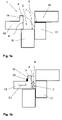
- Figures 1a to 1d show schematically different positions of a compression space 4 of a device 1 according to the invention with a compression space 4 for accommodating the conductors 2, 3 (see Figure 1b ) which can be taken in a connection process.
- Figure 1a a removal position in which the compression space 4 is open
- Figure 1b an insertion position in which there is an insertion opening 9
- Figures 1c and 1d each welding position.
- the compression chamber 4 is defined by an ultrasonically transmitting sonotrode 15, an anvil 16, a lateral delimitation element 17 and a slide element 18.
- the compression space 4 has a right-angled inner edge, which serves as a controlled contact surface when inserting the conductors 2, 3 and determines the shape of the connection point to be created, i.e. the compacting height A and the compacting width B (see Fig Figure 6c ) pretends.
- the compression space 4 is delimited by sections of boundary surfaces 5, 6, 7, 8 adjoining one another.
- the boundary surfaces include a working surface 5 of the ultrasound-transmitting sonotrode 15 and an anvil surface 6 which is arranged opposite the working surface 5 and which is arranged on the anvil 16 .
- the sliding element 18 includes a retaining element 14 which keeps a strand 20 away from the compression space 4 .
- the retaining element 14 is designed here as a protruding element.
- the strand 20 is connected to the conductors 2, 3, which is not explicitly shown in the sectional views 1b to 1d.
- the conductors 2, 3 are compacted by pushing the slide element 28, as shown in FIG figures 1b and 1c is indicated, is shifted towards the lateral delimiting element 17 in the direction S1.
- the compression space 4 is essentially delimited by the sonotrode 15 , the anvil 16 , the delimiting element 17 and the slide element 18 .
- the anvil 16 is first displaced in the direction S2 towards the slide element 18 and then, as in Figure 1d indicated, shifted together with the lateral delimiting element 17 in direction S3 towards the sonotrode 15.
- the strand 20 remains on the side of the retaining element 14 facing away from the slide surface 8 and is thus kept away from the compression space 4 .
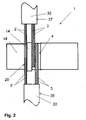
- figure 2 shows a device 1 according to the invention in plan view.
- a first group of conductors 2 of a first cable 32 and a first group of conductors 3 of a second cable 33 are brought up to the compression space 4 from opposite sides.
- a strand 20 runs on the side of the retaining element 14 which faces away from the compression space 4 and is arranged on a slide element 18 .
- the strand 20 is prevented from entering the compression space 4 by the retaining element 14 .
- the conductors 2, 3 can be compacted and welded undisturbed.
- the strand 20 comprises conductors 2', 3' belonging to the two opposite cables 32, 33.
- the conductors 2', 3' of the strand 20 are connected via cable sheaths 37, 38 to the conductors 2, 3 leading into the compression chamber 4.
- the strand 20 may have a previously made weld node.
- a support surface 23 for the at least one strand 20 (not shown explicitly) is arranged in the assembly area 21 adjacent to the retaining element 14 and is designed as a depression.
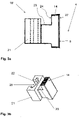
- figure 4 shows another example of a slide element 18 'in a sectional view.
- FIG 5 shows a protective hood 10 in a perspective view.
- the protective hood 10 can be moved over the compression chamber 4, which is not shown in this figure, so that it is covered in the welding position.
- the protective hood 10 is designed in such a way that the conductors 2, 3 and the strand 20, which are also not shown in this figure, can run from an outer area 25 of the protective hood 10 into the compression space 4 when the protective hood 10 covers the compression space 4 in the welding position covers.
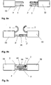
- FIGS 8a to 8c show schematically the method according to the invention.
- a first conductor 2' of the first cable 32 and a first conductor 3' of the second cable 33 are led from opposite sides to a compression chamber 4, which is not explicitly shown.
- a compression chamber 4 which is not explicitly shown.
- the still unconnected ends of the remaining conductors 2, 3 can easily be kept away from the compression space.
- This strand 20 is positioned so that it is kept away from the compression space 4 by the retaining element 14, in which the second conductors 2, 3 of the opposite cables are deposited.
- a second welded connection between the second conductors 2, 3 of the opposite cables 32, 33 can now be produced without any problems.
Landscapes
- Engineering & Computer Science (AREA)
- Manufacturing & Machinery (AREA)
- Mechanical Engineering (AREA)
- Manufacturing Of Electrical Connectors (AREA)
Claims (17)
- Dispositif (1) pour l'assemblage par ultrasons de conducteurs électriques (2, 2', 3, 3'), pour la formation d'une structure de conducteurs avec au moins un premier et un deuxième brin,avec un espace de compression (4) pour recevoir les conducteurs (2, 3), l'espace de compression (4) étant délimité dans une position de soudage par des sections de surfaces de délimitation (5, 6, 7, 8) adjacentes les unes aux autres, lesquelles surfaces de délimitation comprennent une surface de travail (5) d'une sonotrode (15) transmettant des ultrasons et une surface d'enclume (6) disposée en face de la surface de travail (5),caractérisé en ce queau moins un élément de retenue (14) est prévu pour tenir à distance de l'espace de compression (4) au moins un brin (20) qui est relié à au moins une partie des conducteurs (2, 2', 3, 3'), le dispositif (1) étant conçu de telle sorte, que l'élément de retenue (14) maintient le brin (20) à l'écart de l'espace de compression (4) au moins pendant l'assemblage par ultrasons, les surfaces de délimitation comprenant une surface coulissante (8) qui est disposée sur un élément coulissant (18, 18'), et l'élément de retenue (14) étant disposé sur l'élément coulissant (18, 18').
- Dispositif selon la revendication 1, dans lequel l'élément de retenue (14) est réalisé sous la forme d'un élément en saillie sur l'élément coulissant (18, 18').
- Dispositif selon la revendication 1 ou 2, dans lequel l'élément coulissant (18, 18') présente une zone de montage (21) s'écartant de la surface coulissante (8), et l'élément coulissant (18, 18') comprend de préférence dans la zone de montage (21) une surface d'appui (23) pour l'au moins un brin (20), qui est réalisée en particulier sous forme d'abaissement dans la zone de montage (21).
- Dispositif selon l'une des revendications précédentes, dans lequel l'élément coulissant (18, 18') présente un évidement (40) et le dispositif comprend un insert (41, 41') destiné à être inséré dans l'évidement (40), sur lequel est formée une surface d'appui (23) pour le au moins un brin (20).
- Dispositif selon l'une des revendications précédentes, dans lequel le dispositif comprend un capot de protection (10) mobile au-dessus de l'espace de compression (4) de manière à le recouvrir en position de soudage, le capot de protection (10) étant configuré de manière à ce que les conducteurs (2, 2', 3, 3') s'étendent depuis une zone extérieure (25) du dispositif (1) dans l'espace de compression (4), lorsque le capot de protection (10) recouvre l'espace de compression (4) dans la position de soudage et le capot de protection (10) est conçu de telle sorte que le brin (20) s'étend depuis une zone extérieure (25) du dispositif (1) dans le dispositif (1) lorsque le capot de protection (10) recouvre l'espace de compression (4) dans la position de soudage.
- Dispositif selon la revendication 5, dans lequel le capot de protection (10) comprend au moins un premier passage (11) pour le passage des conducteurs (2, 2', 3, 3') et en particulier au moins une première arête d'appui (13) pour l'alignement des conducteurs (2, 2', 3, 3'), ainsi qu'au moins une autre arête d'appui (19) pour l'alignement du au moins un brin (20), et dans lequel il est prévu de préférence un autre passage (12) à travers lequel le brin (20) peut être guidé.
- Dispositif selon la revendication 6, dans lequel l'arête d'appui (19) pour aligner le au moins un brin (20) et au moins une arête d'appui (13) pour aligner les conducteurs (2, 2', 3, 3') sont des parties d'un dispositif de maintien avec lequel les conducteurs (2, 3) et le brin (20) peuvent être fixés à l'extérieur de l'espace de compression (4), en particulier pendant une opération de soudage, et peuvent être libérés à nouveau, en particulier après une opération de soudage.
- Dispositif selon l'une quelconque des revendications précédentes, dans lequel le dispositif (1) comprend un élément coulissant interchangeable (18, 18') avec un élément de retenue (14) et le dispositif (1) comprend notamment au moins un autre élément coulissant sans élément de retenue (14).
- Procédé d'assemblage par ultrasons de conducteurs électriques (2, 3), pour la formation d'une structure conductrice avec au moins un premier et un deuxième brin de conducteurs, dans un espace de compression (4) d'un dispositif (1) pour l'assemblage par ultrasons selon l'une des revendications 1 à 8,l'espace de compression (4) étant, dans une position de soudage, au moins délimité par des sections de surfaces de délimitation (5, 6, 7, 8), lesquelles surfaces de délimitation (5, 6, 7, 8) comprennent une surface de travail (5) d'une sonotrode (15) transmettant des ultrasons et une surface d'enclume (6), un élément de retenue (14) étant prévu pour maintenir à distance de l'espace de compression (4) au moins un brin (20) qui est relié à au moins une partie des conducteurs (2, 3),ledit procédé comprenant les étapes consistant àa.) l'établissement d'une position d'insertion de l'espace de compression (4), dans laquelle l'espace de compression (4) est au moins partiellement ouverte pour l'insertion des conducteurs (2, 3) au niveau d'une ouverture d'insertion (9),b.) l'insertion des conducteurs (2, 3) dans l'espace de compression (4), et caractérisé par les étapes suivantesc.) le positionnement du au moins un brin (20) sur l'élément de retenue (14), en particulier le positionnement du brin sur un côté, s'écartant d'une surface de coulissement (8), d'un élément (14) faisant saillie sur un élément de coulissement (18, 18'),d.) la création d'une position de soudage de l'espace de compression (4) et le maintien du brin (20) à distance de l'espace de compression (4) dans la position de soudage,e.) Soumettre les conducteurs (2, 3) à des vibrations ultrasoniques.
- Procédé selon la revendication 8, dans lequel l'élément de retenue (14) est déplacé de la position d'insertion à une position de soudage, tout en conservant la disposition relative des conducteurs (2, 3) et du au moins un brin (20).
- Procédé selon la revendication 9 ou 10, dans lequel un capot de protection (10) est déplacé au-dessus de l'espace de compression (4) de sorte que celui-ci est recouvert dans la position de soudage, les conducteurs (2, 2', 3, 3') parvenant d'une zone extérieure dans l'espace de compression (4), et le brin (20) parvenant d'une zone extérieure (25) du capot de protection (10) dans le capot de protection (10), et de préférence à nouveau hors de celui-ci.
- Procédé selon la revendication 11, dans lequel les conducteurs (2, 3, 2', 3') s'étendent à travers au moins un premier passage (11) dans le capot de protection (10) vers l'espace de compression (4), et les conducteurs (2, 3, 2', 3') sont alignés en particulier avec au moins un bord d'appui (13), et dans lequel le au moins un brin (20) est aligné par au moins un autre bord d'appui (19), qui est disposé de préférence dans au moins un autre passage (12) du capot de protection (10).
- Procédé selon l'une des revendications 9 à 12, dans lequel des conducteurs (2, 3, 2', 3') sont amenés dans l'espace de compression (4) par deux côtés opposés, et les conducteurs (2, 3, 2', 3') sont reliés entre eux dans la direction longitudinale.
- Procédé selon l'une quelconque des revendications 9 à 13, dans lequel le brin (20) comprend au moins un conducteur allongé qui est passé devant l'espace de compression (4) pendant l'assemblage.
- Procédé selon l'une des revendications 9 à 14, dans lequel un premier groupe de conducteurs (2', 3') d'au moins deux câbles (32, 33) amenés par des côtés opposés à l'espace de compression (4) est inséré (4) dans l'espace de compression, en particulier au moins un deuxième groupe de conducteurs (2, 3) est positionné de manière à être maintenu à distance de l'espace de compression (4) par l'élément de retenue (14), on réalise une première soudure du premier groupe de conducteurs (2', 3'), on positionne ensuite les conducteurs (2', 3') reliés à la première soudure de manière à ce qu'ils soient maintenus à distance de l'espace de compression (4) par l'élément de retenue (14), on dépose le deuxième groupe de conducteurs (2, 3) dans l'espace de compression (4) et on réalise une deuxième soudure du deuxième groupe de conducteurs (2, 3).
- Procédé selon l'une des revendications 9 à 15,dans lequel, dans une première étape, un premier noeud en Y (29) est réalisé entre des conducteurs (2') de deux câbles (32) amenés par un premier côté à l'espace de compression (4) et des conducteurs (3') d'un troisième câble (33) amené par l'autre côté à l'espace de compression (4), dans une deuxième étape, le premier noeud en Y (29) est positionné de manière à être maintenu à distance de l'espace de compression (4) par l'élément de retenue (14), d'autres conducteurs (2, 3) des trois câbles (32, 33) sont insérés dans l'espace de compression (4) et un autre noeud en Y (29) est réaliséou dans lequel dans une première étape, un premier noeud en X (34) est réalisé entre des conducteurs (2') de deux câbles (32) qui sont amenés d'un premier côté à l'espace de compression (4) et des conducteurs (3') de deux autres câbles (33) qui sont amenés de l'autre côté à l'espace de compression (4), et dans une deuxième étape, le premier noeud en X (34) est positionné de manière à être maintenu à l'écart de l'espace de compression (4) par l'élément de retenue (14), d'autres conducteurs (2, 3) des quatre câbles (32, 33) sont insérés dans l'espace de compression (4) et un autre noeud en X (34) est réalisé.
- Utilisation d'un élément de retenue (14) disposé sur un élément coulissant (18, 18') pour maintenir un brin conducteur (20) à distance d'un espace de compression (4) destinée à recevoir des conducteurs électriques (2, 3) dans un dispositif d'assemblage par ultrasons desdits conducteurs électriques (2, 3) selon l'une quelconque des revendications 1 à 8.
Applications Claiming Priority (1)
| Application Number | Priority Date | Filing Date | Title |
|---|---|---|---|
| PCT/EP2017/076351 WO2019076433A1 (fr) | 2017-10-16 | 2017-10-16 | Dispositif et procédé pour l'assemblage par ultrasons de conducteurs électriques |
Publications (2)
| Publication Number | Publication Date |
|---|---|
| EP3698441A1 EP3698441A1 (fr) | 2020-08-26 |
| EP3698441B1 true EP3698441B1 (fr) | 2022-08-10 |
Family
ID=60117682
Family Applications (1)
| Application Number | Title | Priority Date | Filing Date |
|---|---|---|---|
| EP17784638.3A Active EP3698441B1 (fr) | 2017-10-16 | 2017-10-16 | Dispositif et procédé pour l'assemblage par ultrasons de conducteurs électriques |
Country Status (3)
| Country | Link |
|---|---|
| EP (1) | EP3698441B1 (fr) |
| DE (1) | DE112017007765A5 (fr) |
| WO (1) | WO2019076433A1 (fr) |
Families Citing this family (3)
| Publication number | Priority date | Publication date | Assignee | Title |
|---|---|---|---|---|
| EP3906133B1 (fr) * | 2019-11-05 | 2022-04-20 | Schunk Sonosystems Gmbh | Dispositif de soudage par ultrasons avec détection de position de pièces de jonction |
| DE102020113672B4 (de) * | 2020-05-20 | 2022-03-03 | Lisa Dräxlmaier GmbH | Verfahren und vorrichtung zum verschweissen von zumindest drei kabeln mit je zwei aus mantelenden der kabel herausragenden adern |
| HUE070851T2 (hu) * | 2020-07-30 | 2025-07-28 | Schunk Sonosystems Gmbh | Többlépcsõs eljárás csomópontok hegesztésére ultrahangos hegesztõkészülékkel |
Citations (1)
| Publication number | Priority date | Publication date | Assignee | Title |
|---|---|---|---|---|
| DE102015117020A1 (de) * | 2015-10-06 | 2017-04-06 | Kromberg & Schubert Gmbh | Schweißverbinder |
Family Cites Families (3)
| Publication number | Priority date | Publication date | Assignee | Title |
|---|---|---|---|---|
| DE102011014801B4 (de) * | 2011-03-23 | 2019-08-08 | Audi Ag | Verfahren zum Verschweißen von Leitern |
| EP2786835A1 (fr) * | 2013-04-02 | 2014-10-08 | Telsonic Holding AG | Dispositif et procédé de soudage par ultrasons avec une surface de confinement déplaçable |
| DE102013209314B3 (de) * | 2013-05-21 | 2014-06-26 | Lisa Dräxlmaier GmbH | Verfahren zum elektrischen Verbinden einer elektrischen Leitung mit einem Kontaktteil |
-
2017
- 2017-10-16 DE DE112017007765.6T patent/DE112017007765A5/de not_active Withdrawn
- 2017-10-16 WO PCT/EP2017/076351 patent/WO2019076433A1/fr not_active Ceased
- 2017-10-16 EP EP17784638.3A patent/EP3698441B1/fr active Active
Patent Citations (1)
| Publication number | Priority date | Publication date | Assignee | Title |
|---|---|---|---|---|
| DE102015117020A1 (de) * | 2015-10-06 | 2017-04-06 | Kromberg & Schubert Gmbh | Schweißverbinder |
Also Published As
| Publication number | Publication date |
|---|---|
| EP3698441A1 (fr) | 2020-08-26 |
| WO2019076433A1 (fr) | 2019-04-25 |
| DE112017007765A5 (de) | 2020-04-23 |
Similar Documents
| Publication | Publication Date | Title |
|---|---|---|
| EP1960151B1 (fr) | Procede pour produire une soudure entre des conducteurs electriques par un procede de soudage par ultrasons | |
| EP2605881B1 (fr) | Procédé et système de soudage de conducteurs électriques | |
| DE102013101876B3 (de) | Verfahren zum stoffschlüssigen Fügen eines Kabels mit einem Anschlusselement sowie konfiguriertes Kabel | |
| EP1771274B1 (fr) | Procede pour realiser un assemblage par soudure | |
| EP2609655B1 (fr) | Procédé et dispositif de connexion d'un conducteur électrique à un élément de contact électrique | |
| EP3069419B1 (fr) | Dispositif de soudage de conducteurs électriques | |
| DE10218400B4 (de) | Abschirmanordnung an einem Abschirmflachkabel und Verfahren zu deren Herstellung | |
| EP0143936A1 (fr) | Dispositif pour joindre ou comprimer des conducteurs électriques | |
| EP3698441B1 (fr) | Dispositif et procédé pour l'assemblage par ultrasons de conducteurs électriques | |
| DE19909322A1 (de) | Verbindungsstruktur für ummantelte Leitungen | |
| DE1615659C3 (de) | Verfahren und Vorrichtung zum elektrischen Verbinden einzelner Leitungsdrähte einer Gruppe von Leitugsdrähten | |
| EP3676043A1 (fr) | Procédé pour souder des conducteurs électriques au moyen d'ultrasons, et dispositif de soudage de métaux par ultrasons | |
| DE19909335A1 (de) | Verbindungsstruktur für ummantelte Leitungen | |
| DE102012007846A1 (de) | Crimpvorrichtung zum Verbinden eines elektrischen Leiters mit einem elektrischen Kontaktteil, das verformbare Schenkel aufweist | |
| DE19527123A1 (de) | Verfahren zur elektrischen Verbindung zweier elektrischer Bauteile miteinander | |
| DE102016121909B4 (de) | Dichtung von Leitungsverbindern | |
| DE102015117020B4 (de) | Verfahren zum Herstellen einer Leitungsabdichtung eines Leitungsstrangs und Verfahren zur Herstellung einer gedichteten Leitungsverbindung | |
| EP0474113B1 (fr) | Dispositif de connexion pour câbles multifilaires | |
| EP3631912B1 (fr) | Procédé de contact pour conducteurs isolés au vernis | |
| EP3474391B1 (fr) | Procédé de raccordement d'au moins deux fils à plusieurs brins au moyen d'ultrasons | |
| DE4435090C1 (de) | Vorrichtung zum Herstellen von für die Montage vorgefertigten, flexiblen, in der Länge zugeschnittenen, elektrischen Litzenleitungen | |
| DE102016223475B4 (de) | Verbindungsanordnung und Verfahren zur Herstellung einer Verbindungsanordnung für Litzenleiter in einer Führung | |
| DE10161857C2 (de) | Vorrichtung zum leitenden Verbinden mindestens eines Kontaktes an einer Leiterbahn in einem ein- oder mehradrigen Flachbandkabel | |
| EP0000731B1 (fr) | Procédé de réalisation de dérivations sur un câble électrique isolé | |
| EP4697507A1 (fr) | Procédé de connexion de conducteurs électriques, en particulier de vibrations ultrasonores, dispositif de connexion, procédé de connexion de conducteurs électriques à l'aide du dispositif de connexion et procédé de connexion électrique |
Legal Events
| Date | Code | Title | Description |
|---|---|---|---|
| STAA | Information on the status of an ep patent application or granted ep patent |
Free format text: STATUS: UNKNOWN |
|
| STAA | Information on the status of an ep patent application or granted ep patent |
Free format text: STATUS: THE INTERNATIONAL PUBLICATION HAS BEEN MADE |
|
| PUAI | Public reference made under article 153(3) epc to a published international application that has entered the european phase |
Free format text: ORIGINAL CODE: 0009012 |
|
| STAA | Information on the status of an ep patent application or granted ep patent |
Free format text: STATUS: REQUEST FOR EXAMINATION WAS MADE |
|
| 17P | Request for examination filed |
Effective date: 20200514 |
|
| AK | Designated contracting states |
Kind code of ref document: A1 Designated state(s): AL AT BE BG CH CY CZ DE DK EE ES FI FR GB GR HR HU IE IS IT LI LT LU LV MC MK MT NL NO PL PT RO RS SE SI SK SM TR |
|
| AX | Request for extension of the european patent |
Extension state: BA ME |
|
| DAV | Request for validation of the european patent (deleted) | ||
| DAX | Request for extension of the european patent (deleted) | ||
| STAA | Information on the status of an ep patent application or granted ep patent |
Free format text: STATUS: EXAMINATION IS IN PROGRESS |
|
| 17Q | First examination report despatched |
Effective date: 20210622 |
|
| GRAP | Despatch of communication of intention to grant a patent |
Free format text: ORIGINAL CODE: EPIDOSNIGR1 |
|
| STAA | Information on the status of an ep patent application or granted ep patent |
Free format text: STATUS: GRANT OF PATENT IS INTENDED |
|
| GRAS | Grant fee paid |
Free format text: ORIGINAL CODE: EPIDOSNIGR3 |
|
| GRAA | (expected) grant |
Free format text: ORIGINAL CODE: 0009210 |
|
| STAA | Information on the status of an ep patent application or granted ep patent |
Free format text: STATUS: THE PATENT HAS BEEN GRANTED |
|
| INTG | Intention to grant announced |
Effective date: 20220628 |
|
| AK | Designated contracting states |
Kind code of ref document: B1 Designated state(s): AL AT BE BG CH CY CZ DE DK EE ES FI FR GB GR HR HU IE IS IT LI LT LU LV MC MK MT NL NO PL PT RO RS SE SI SK SM TR |
|
| REG | Reference to a national code |
Ref country code: AT Ref legal event code: REF Ref document number: 1511251 Country of ref document: AT Kind code of ref document: T Effective date: 20220815 Ref country code: CH Ref legal event code: EP |
|
| REG | Reference to a national code |
Ref country code: IE Ref legal event code: FG4D Free format text: LANGUAGE OF EP DOCUMENT: GERMAN |
|
| REG | Reference to a national code |
Ref country code: DE Ref legal event code: R096 Ref document number: 502017013607 Country of ref document: DE |
|
| REG | Reference to a national code |
Ref country code: NL Ref legal event code: MP Effective date: 20220810 |
|
| REG | Reference to a national code |
Ref country code: LT Ref legal event code: MG9D |
|
| PG25 | Lapsed in a contracting state [announced via postgrant information from national office to epo] |
Ref country code: SE Free format text: LAPSE BECAUSE OF FAILURE TO SUBMIT A TRANSLATION OF THE DESCRIPTION OR TO PAY THE FEE WITHIN THE PRESCRIBED TIME-LIMIT Effective date: 20220810 Ref country code: RS Free format text: LAPSE BECAUSE OF FAILURE TO SUBMIT A TRANSLATION OF THE DESCRIPTION OR TO PAY THE FEE WITHIN THE PRESCRIBED TIME-LIMIT Effective date: 20220810 Ref country code: PT Free format text: LAPSE BECAUSE OF FAILURE TO SUBMIT A TRANSLATION OF THE DESCRIPTION OR TO PAY THE FEE WITHIN THE PRESCRIBED TIME-LIMIT Effective date: 20221212 Ref country code: NO Free format text: LAPSE BECAUSE OF FAILURE TO SUBMIT A TRANSLATION OF THE DESCRIPTION OR TO PAY THE FEE WITHIN THE PRESCRIBED TIME-LIMIT Effective date: 20221110 Ref country code: NL Free format text: LAPSE BECAUSE OF FAILURE TO SUBMIT A TRANSLATION OF THE DESCRIPTION OR TO PAY THE FEE WITHIN THE PRESCRIBED TIME-LIMIT Effective date: 20220810 Ref country code: LV Free format text: LAPSE BECAUSE OF FAILURE TO SUBMIT A TRANSLATION OF THE DESCRIPTION OR TO PAY THE FEE WITHIN THE PRESCRIBED TIME-LIMIT Effective date: 20220810 Ref country code: LT Free format text: LAPSE BECAUSE OF FAILURE TO SUBMIT A TRANSLATION OF THE DESCRIPTION OR TO PAY THE FEE WITHIN THE PRESCRIBED TIME-LIMIT Effective date: 20220810 Ref country code: FI Free format text: LAPSE BECAUSE OF FAILURE TO SUBMIT A TRANSLATION OF THE DESCRIPTION OR TO PAY THE FEE WITHIN THE PRESCRIBED TIME-LIMIT Effective date: 20220810 |
|
| PG25 | Lapsed in a contracting state [announced via postgrant information from national office to epo] |
Ref country code: PL Free format text: LAPSE BECAUSE OF FAILURE TO SUBMIT A TRANSLATION OF THE DESCRIPTION OR TO PAY THE FEE WITHIN THE PRESCRIBED TIME-LIMIT Effective date: 20220810 Ref country code: IS Free format text: LAPSE BECAUSE OF FAILURE TO SUBMIT A TRANSLATION OF THE DESCRIPTION OR TO PAY THE FEE WITHIN THE PRESCRIBED TIME-LIMIT Effective date: 20221210 Ref country code: HR Free format text: LAPSE BECAUSE OF FAILURE TO SUBMIT A TRANSLATION OF THE DESCRIPTION OR TO PAY THE FEE WITHIN THE PRESCRIBED TIME-LIMIT Effective date: 20220810 Ref country code: GR Free format text: LAPSE BECAUSE OF FAILURE TO SUBMIT A TRANSLATION OF THE DESCRIPTION OR TO PAY THE FEE WITHIN THE PRESCRIBED TIME-LIMIT Effective date: 20221111 |
|
| PG25 | Lapsed in a contracting state [announced via postgrant information from national office to epo] |
Ref country code: SM Free format text: LAPSE BECAUSE OF FAILURE TO SUBMIT A TRANSLATION OF THE DESCRIPTION OR TO PAY THE FEE WITHIN THE PRESCRIBED TIME-LIMIT Effective date: 20220810 Ref country code: RO Free format text: LAPSE BECAUSE OF FAILURE TO SUBMIT A TRANSLATION OF THE DESCRIPTION OR TO PAY THE FEE WITHIN THE PRESCRIBED TIME-LIMIT Effective date: 20220810 Ref country code: ES Free format text: LAPSE BECAUSE OF FAILURE TO SUBMIT A TRANSLATION OF THE DESCRIPTION OR TO PAY THE FEE WITHIN THE PRESCRIBED TIME-LIMIT Effective date: 20220810 Ref country code: DK Free format text: LAPSE BECAUSE OF FAILURE TO SUBMIT A TRANSLATION OF THE DESCRIPTION OR TO PAY THE FEE WITHIN THE PRESCRIBED TIME-LIMIT Effective date: 20220810 Ref country code: CZ Free format text: LAPSE BECAUSE OF FAILURE TO SUBMIT A TRANSLATION OF THE DESCRIPTION OR TO PAY THE FEE WITHIN THE PRESCRIBED TIME-LIMIT Effective date: 20220810 |
|
| REG | Reference to a national code |
Ref country code: DE Ref legal event code: R097 Ref document number: 502017013607 Country of ref document: DE |
|
| PG25 | Lapsed in a contracting state [announced via postgrant information from national office to epo] |
Ref country code: SK Free format text: LAPSE BECAUSE OF FAILURE TO SUBMIT A TRANSLATION OF THE DESCRIPTION OR TO PAY THE FEE WITHIN THE PRESCRIBED TIME-LIMIT Effective date: 20220810 Ref country code: MC Free format text: LAPSE BECAUSE OF FAILURE TO SUBMIT A TRANSLATION OF THE DESCRIPTION OR TO PAY THE FEE WITHIN THE PRESCRIBED TIME-LIMIT Effective date: 20220810 Ref country code: EE Free format text: LAPSE BECAUSE OF FAILURE TO SUBMIT A TRANSLATION OF THE DESCRIPTION OR TO PAY THE FEE WITHIN THE PRESCRIBED TIME-LIMIT Effective date: 20220810 |
|
| PLBE | No opposition filed within time limit |
Free format text: ORIGINAL CODE: 0009261 |
|
| STAA | Information on the status of an ep patent application or granted ep patent |
Free format text: STATUS: NO OPPOSITION FILED WITHIN TIME LIMIT |
|
| REG | Reference to a national code |
Ref country code: BE Ref legal event code: MM Effective date: 20221031 |
|
| PG25 | Lapsed in a contracting state [announced via postgrant information from national office to epo] |
Ref country code: LU Free format text: LAPSE BECAUSE OF NON-PAYMENT OF DUE FEES Effective date: 20221016 Ref country code: AL Free format text: LAPSE BECAUSE OF FAILURE TO SUBMIT A TRANSLATION OF THE DESCRIPTION OR TO PAY THE FEE WITHIN THE PRESCRIBED TIME-LIMIT Effective date: 20220810 |
|
| 26N | No opposition filed |
Effective date: 20230511 |
|
| GBPC | Gb: european patent ceased through non-payment of renewal fee |
Effective date: 20221110 |
|
| PG25 | Lapsed in a contracting state [announced via postgrant information from national office to epo] |
Ref country code: FR Free format text: LAPSE BECAUSE OF NON-PAYMENT OF DUE FEES Effective date: 20221031 |
|
| PG25 | Lapsed in a contracting state [announced via postgrant information from national office to epo] |
Ref country code: SI Free format text: LAPSE BECAUSE OF FAILURE TO SUBMIT A TRANSLATION OF THE DESCRIPTION OR TO PAY THE FEE WITHIN THE PRESCRIBED TIME-LIMIT Effective date: 20220810 |
|
| PG25 | Lapsed in a contracting state [announced via postgrant information from national office to epo] |
Ref country code: BE Free format text: LAPSE BECAUSE OF NON-PAYMENT OF DUE FEES Effective date: 20221031 |
|
| PG25 | Lapsed in a contracting state [announced via postgrant information from national office to epo] |
Ref country code: IE Free format text: LAPSE BECAUSE OF NON-PAYMENT OF DUE FEES Effective date: 20221016 Ref country code: GB Free format text: LAPSE BECAUSE OF NON-PAYMENT OF DUE FEES Effective date: 20221110 |
|
| REG | Reference to a national code |
Ref country code: AT Ref legal event code: MM01 Ref document number: 1511251 Country of ref document: AT Kind code of ref document: T Effective date: 20221016 |
|
| PG25 | Lapsed in a contracting state [announced via postgrant information from national office to epo] |
Ref country code: AT Free format text: LAPSE BECAUSE OF NON-PAYMENT OF DUE FEES Effective date: 20221016 |
|
| PG25 | Lapsed in a contracting state [announced via postgrant information from national office to epo] |
Ref country code: CY Free format text: LAPSE BECAUSE OF FAILURE TO SUBMIT A TRANSLATION OF THE DESCRIPTION OR TO PAY THE FEE WITHIN THE PRESCRIBED TIME-LIMIT Effective date: 20220810 |
|
| PG25 | Lapsed in a contracting state [announced via postgrant information from national office to epo] |
Ref country code: MK Free format text: LAPSE BECAUSE OF FAILURE TO SUBMIT A TRANSLATION OF THE DESCRIPTION OR TO PAY THE FEE WITHIN THE PRESCRIBED TIME-LIMIT Effective date: 20220810 Ref country code: IT Free format text: LAPSE BECAUSE OF FAILURE TO SUBMIT A TRANSLATION OF THE DESCRIPTION OR TO PAY THE FEE WITHIN THE PRESCRIBED TIME-LIMIT Effective date: 20220810 Ref country code: HU Free format text: LAPSE BECAUSE OF FAILURE TO SUBMIT A TRANSLATION OF THE DESCRIPTION OR TO PAY THE FEE WITHIN THE PRESCRIBED TIME-LIMIT; INVALID AB INITIO Effective date: 20171016 |
|
| PG25 | Lapsed in a contracting state [announced via postgrant information from national office to epo] |
Ref country code: BG Free format text: LAPSE BECAUSE OF FAILURE TO SUBMIT A TRANSLATION OF THE DESCRIPTION OR TO PAY THE FEE WITHIN THE PRESCRIBED TIME-LIMIT Effective date: 20220810 |
|
| PG25 | Lapsed in a contracting state [announced via postgrant information from national office to epo] |
Ref country code: MT Free format text: LAPSE BECAUSE OF FAILURE TO SUBMIT A TRANSLATION OF THE DESCRIPTION OR TO PAY THE FEE WITHIN THE PRESCRIBED TIME-LIMIT Effective date: 20220810 |
|
| REG | Reference to a national code |
Ref country code: CH Ref legal event code: U11 Free format text: ST27 STATUS EVENT CODE: U-0-0-U10-U11 (AS PROVIDED BY THE NATIONAL OFFICE) Effective date: 20251101 |
|
| PG25 | Lapsed in a contracting state [announced via postgrant information from national office to epo] |
Ref country code: TR Free format text: LAPSE BECAUSE OF FAILURE TO SUBMIT A TRANSLATION OF THE DESCRIPTION OR TO PAY THE FEE WITHIN THE PRESCRIBED TIME-LIMIT Effective date: 20220810 |
|
| PGFP | Annual fee paid to national office [announced via postgrant information from national office to epo] |
Ref country code: DE Payment date: 20250819 Year of fee payment: 9 |
|
| PGFP | Annual fee paid to national office [announced via postgrant information from national office to epo] |
Ref country code: CH Payment date: 20251101 Year of fee payment: 9 |