EP3698664A1 - Gants - Google Patents
Gants Download PDFInfo
- Publication number
- EP3698664A1 EP3698664A1 EP19158983.7A EP19158983A EP3698664A1 EP 3698664 A1 EP3698664 A1 EP 3698664A1 EP 19158983 A EP19158983 A EP 19158983A EP 3698664 A1 EP3698664 A1 EP 3698664A1
- Authority
- EP
- European Patent Office
- Prior art keywords
- glove
- shaft
- zipper
- tab
- flap
- Prior art date
- Legal status (The legal status is an assumption and is not a legal conclusion. Google has not performed a legal analysis and makes no representation as to the accuracy of the status listed.)
- Granted
Links
Images

Classifications
-
- A—HUMAN NECESSITIES
- A41—WEARING APPAREL
- A41D—OUTERWEAR; PROTECTIVE GARMENTS; ACCESSORIES
- A41D19/00—Gloves
- A41D19/0044—Cuff portions
- A41D19/0048—Cuff portions with cuff securing features
-
- A—HUMAN NECESSITIES
- A41—WEARING APPAREL
- A41D—OUTERWEAR; PROTECTIVE GARMENTS; ACCESSORIES
- A41D19/00—Gloves
- A41D19/015—Protective gloves
- A41D19/01582—Protective gloves with means to restrain or support the hand
-
- A—HUMAN NECESSITIES
- A41—WEARING APPAREL
- A41F—GARMENT FASTENINGS; SUSPENDERS
- A41F1/00—Fastening devices specially adapted for garments
- A41F1/06—Glove fasteners
-
- A—HUMAN NECESSITIES
- A41—WEARING APPAREL
- A41D—OUTERWEAR; PROTECTIVE GARMENTS; ACCESSORIES
- A41D19/00—Gloves
- A41D19/015—Protective gloves
-
- A—HUMAN NECESSITIES
- A41—WEARING APPAREL
- A41D—OUTERWEAR; PROTECTIVE GARMENTS; ACCESSORIES
- A41D2600/00—Uses of garments specially adapted for specific purposes
- A41D2600/20—Uses of garments specially adapted for specific purposes for working activities
Definitions
- the invention relates to an operational glove.
- Such operational gloves are generally worn by people in operations in which harsh environmental conditions can exist. As a result, the gloves are made of stable materials that are insensitive to such environmental conditions.
- the operational glove In order to adequately protect a person in such operations, it is not sufficient for the operational glove itself to guarantee protection against environmental influences. Rather, it is necessary for the deployment gloves to form a tight seal with a deployment jacket which a person wears in an action, in particular to prevent water from penetrating between the deployment glove and the deployment jacket.
- gauntlet glove In order to meet these requirements, it is known to design deployment gloves as gauntlets.
- a gauntlet glove has a gauntlet on the glove body which is pulled over the operational jacket.
- the advantage of such a gauntlet glove is that the forearm of a person wearing the gauntlet glove is completely covered. It is also advantageous that the gauntlet can be put on relatively easily, although putting it over the jacket requires a certain amount of time.
- gauntlet gloves A major disadvantage of gauntlet gloves is that liquids, in particular water, can penetrate the gauntlet from above through the sleeve of the jacket, which is problematic in particular when deployed in the rain.
- the invention is based on the object of providing an operational glove which has a high level of functionality and can also be put on or taken off easily and quickly.
- the invention relates to an operational glove with a glove body, glove fingers and a shaft adjoining the glove body.
- the shaft can be narrowed by means of a locking system.
- the locking system has a flap which is fastened at one end to the deployment glove and which has a mechanical locking means which, in order to narrow the shaft, is guided onto a corresponding mechanical locking means by a closing movement of the flap, whereby a mechanical lock is formed.
- a zip fastener is provided on the shaft, the slide of which is over a coupling means is connected to the flap in such a way that the zipper is closed with the closing movement of the flap.
- the deployment glove is designed for outdoor use, and is designed to be resistant to harsh environmental influences such as splash water and high temperatures.
- the deployment glove consists of appropriately resistant, in particular waterproof and temperature-resistant materials.
- the insert glove has an extension in the form of a shaft, which adjoins the glove body and advantageously consists of the same material as the shaft.
- the shaft is equipped with a locking system which has mechanical locking means on the one hand and a zip fastener on the other.
- the slide of the zip fastener is connected via a coupling means to the tab, which has a mechanical closure means, whereby the latter are coupled in terms of movement. It is thereby achieved that by a closing movement of the flap, in which the mechanical locking means on the flap is guided to a corresponding mechanical locking means preferably arranged directly on the shaft, the slide of the zipper is moved along via the coupling means so that it is automatically closed.
- the mechanical fastener with the mechanical locking means can consequently be opened and closed and at the same time the zip fastener can also be opened or closed by moving the flap.
- the flap can be operated much more easily by a person who is already wearing a deployment glove than the slide of a zipper.
- the operation of the locking system according to the invention is therefore extremely simple and user-friendly.
- Another essential advantage of the invention is that the locking system according to the invention can be opened and closed very quickly, so that the requirements of the standard DIN EN 659: 2008-06 can be met.
- This standard requires that the emergency glove can be used as a fire brigade glove in a maximum of 3 seconds. This requirement is met with the deployment glove according to the invention, so that it can be used as a fire fighting glove.
- the operational glove according to the invention can of course also be used in other areas of use, for example as a police glove or rescue glove.
- the insert glove according to the invention is narrowed in the area of the shaft. It is particularly advantageous that when the zipper is closed, the shaft is narrowed over the entire length of the zipper.
- the flap with the mechanical locking means increases this effect when the flap is closed and its mechanical locking means is in contact with the corresponding mechanical locking means and forms the mechanical lock. Furthermore, the mechanical lock provides additional security, as the flap lies over the zip and partially covers it.
- the deployment glove according to the invention Due to the narrowing of the shaft of the deployment glove according to the invention, it can be inserted easily and quickly into the sleeve of a deployment jacket.
- the sleeve which is guided over the shaft, safely and reliably prevents it Penetration of liquids or hazardous substances between the operational glove and the operational jacket.
- the deployment glove according to the invention thus has a high level of functionality.
- the zipper is arranged on the back of the shaft.
- the zip fastener can also be provided on the inside of the shaft.
- the fastening of the flap on the shaft and the corresponding mechanical locking means are on both sides of the zipper.
- the tab is thus also fixed in the area of the back of the deployment glove and can therefore be easily operated by the person wearing the deployment glove.
- the mechanical fastening means are designed in the form of Velcro fasteners.
- the Velcro fasteners only need to be pressed against each other to produce the mechanical fastener, which can be done very easily.
- the mechanical fastener can be released just as easily by pulling the first Velcro fastener off the second Velcro fastener.
- the mechanical fastening means are generally not limited to Velcro fasteners. In principle, other closure means such as hooks or the like can also be used.
- the coupling means that connects the flap to the slide of the zipper is generally formed by a flexible, that is to say easily bendable, element which, however, is advantageously not elastically deformable in the longitudinal direction and therefore cannot be stretched. A reproducible movement coupling of the flap with the zip fastener is thereby obtained.
- a band is provided as the coupling means, one longitudinal end of which is connected to the tab and the second longitudinal end of which is connected to a slide handle on the slide of the zip fastener.
- the dimensions and arrangement of the flap with the mechanical fastener and the corresponding mechanical fastener and the zipper are coordinated.
- the flap advantageously runs in its closed position transversely to the longitudinal direction of the deployment glove.
- the longitudinal axis of the zipper runs obliquely to the longitudinal direction of the insert glove, with the closed end of the zipper being arranged on the inside of the shaft and closer to the fastening of the flap than the open end of the zipper, which is in the area of the outer edge of the shaft .
- the longitudinal axis of the zip fastener advantageously runs at an angle of inclination ⁇ with 0 ° ⁇ 90 °.
- the angle of inclination ⁇ is particularly advantageously in the range 20 ° ⁇ ⁇ 60 °.
- the connection of the slide to the flap with the coupling means always generates a force component on the slide when the flap is moved
- the longitudinal direction of the zipper is directed and thus causes the zipper to open or close.
- the individual components of the locking system are adjusted in such a way that the zip fastener is completely closed or opened when the flap is closed or opened. This can be achieved surprisingly easily by a suitable choice of the length of the zip fastener and its orientation on the shaft at its angle of inclination to the longitudinal direction of the insert glove.
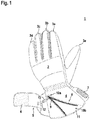
- the Figures 1 and 2 show an exemplary embodiment of the deployment glove 1 according to the invention.
- the deployment glove 1 is designed as a firefighter's glove and the outside is preferably made of waterproof or water-repellent and also heat-resistant materials.
- the deployment glove 1 can also be designed as a police glove or rescue glove.
- the insert glove 1 is designed as a finger glove and accordingly has a glove body 2 with five adjoining glove fingers 3a to 3e, one glove finger 3e being designed as a thumb.
- the insert glove 1 has an extension in the form of a shaft 4, which consists of the same material as the glove body 2.
- a locking system is provided on the shaft 4.
- the locking system consists on the one hand of a mechanical locking system. This comprises, on the one hand, a tab 5 with a mechanical fastening means 6 in the form of a Velcro fastener and, on the other hand, a corresponding mechanical fastening means 7, which is also designed in the form of a Velcro fastener.
- the flap 5 forms an elongated, flat body which is fastened, preferably sewn, to the deployment glove 1 with one end on its longitudinal side.
- the flap 5 is attached to a first lateral edge of the insert glove 1 in the region of the shaft 4.
- the Velcro fastener is fastened to the inside of the flap 5 in the area of the free end of the flap 5, this being preferably sewn onto the flap 5.
- the corresponding mechanical fastening means 7 in the form of a second Velcro fastener is attached to the opposite lateral edge of the shaft 4.
- the Velcro fastener is preferably sewn onto the deployment glove 1.
- the tab 5 forms a flexible, bendable body.
- a mechanical closure is formed in that a person picks up the tab 5 and guides the mechanical closure means 6 provided there against the corresponding mechanical closure means 7 directly on the deployment glove 1.
- the mechanical fastener is educated. This causes a narrowing of the shaft 4.
- the tab 5 runs transversely, that is, perpendicular to the longitudinal direction of the deployment glove 1.
- the locking system additionally has a zip fastener 8 which, in a known manner, has a slider 9 with which the zip fastener 8 can be opened.
- the zip fastener 8 has two strips which are brought together at a closed end 10a. The opposite open end 10b of the zip fastener 8 can be closed with the slide 9.
- an insert part 11 is located under the zipper 8 and covers the open area.
- the slide 9 is coupled to the tab 5 via a coupling means.
- the coupling means consists of a band 12, which is fastened with another longitudinal end to a slide handle 13 on the slide 9 of the zip fastener 8.
- the band 12 is a flexible, bendable flat body, but the band 12 is not elastic in the longitudinal direction.
- the band 12 is preferably made of a textile material.
- the slider 9 is coupled in terms of movement to the tab 5 by the band 12.
- the coupling is designed in such a way that when the flap 5 closes (that is, when the mechanical locking means 6 is guided to the corresponding mechanical locking means 7), the zip fastener 8 is automatically closed, and that when the flap is opened (i.e., the mechanical closure means 6 from the corresponding mechanical closure means 7) the zipper 8 is opened automatically.
- the zip fastener 8 lies between the location of the fastening of the flap 5 and the location of the fastening of the corresponding mechanical closure means 7.
- the angle of inclination ⁇ of the longitudinal axis of the zipper 8 to the longitudinal direction of the insert glove 1 is in the range 0 ⁇ ⁇ 90 °, that is, the longitudinal axis of the zipper 8 runs not only obliquely to the longitudinal direction of the insert glove 1, but also inclined to the transverse direction , in which the tab 5 runs when the mechanical lock is established.
- the angle of inclination is advantageously in the range 20 ° ⁇ ⁇ 60 °.
- the angle of inclination ⁇ is particularly advantageously between 35 ° and 40 °.
- the open end 10b of the zipper 8 is oriented further towards the edge of the shaft 4 than its closed end 10a.
- the open end 10b of the zip fastener 8 opens out at the edge of the shaft 4, while the closed end 10a of the zip fastener 8 lies in the region of the shaft 4 facing the glove body 2.
- the closed end 10a of the zipper 8 is closer to the fastening of the flap 5 on the deployment glove 1 than the open end 10b.
- the zip fastener 8 is automatically actuated and opened and closed by opening and closing the flap 5.
- the zipper 8 is completely closed, whereby the shaft 4 is narrowed over the entire length of the zipper 8.
- the mechanical fastener supports the narrowing and lies protectively over the zip 8.
- the shaft 4 of the deployment glove 1 can simply be inserted into a sleeve of a deployment jacket.
- a person who wears the operational jacket and the operational gloves 1 is thus well protected against environmental influences, since no liquids or hazardous substances can penetrate between the operational gloves 1 and the operational jacket.
Landscapes
- Engineering & Computer Science (AREA)
- Textile Engineering (AREA)
- Gloves (AREA)
Priority Applications (2)
| Application Number | Priority Date | Filing Date | Title |
|---|---|---|---|
| EP19158983.7A EP3698664B1 (fr) | 2019-02-25 | 2019-02-25 | Gants |
| ES19158983T ES2901723T3 (es) | 2019-02-25 | 2019-02-25 | Guante |
Applications Claiming Priority (1)
| Application Number | Priority Date | Filing Date | Title |
|---|---|---|---|
| EP19158983.7A EP3698664B1 (fr) | 2019-02-25 | 2019-02-25 | Gants |
Publications (2)
| Publication Number | Publication Date |
|---|---|
| EP3698664A1 true EP3698664A1 (fr) | 2020-08-26 |
| EP3698664B1 EP3698664B1 (fr) | 2021-09-29 |
Family
ID=65576157
Family Applications (1)
| Application Number | Title | Priority Date | Filing Date |
|---|---|---|---|
| EP19158983.7A Active EP3698664B1 (fr) | 2019-02-25 | 2019-02-25 | Gants |
Country Status (2)
| Country | Link |
|---|---|
| EP (1) | EP3698664B1 (fr) |
| ES (1) | ES2901723T3 (fr) |
Cited By (1)
| Publication number | Priority date | Publication date | Assignee | Title |
|---|---|---|---|---|
| DE102021111851A1 (de) | 2021-05-06 | 2022-11-10 | Friedrich Seiz Gmbh | Einsatz-Handschuh |
Families Citing this family (1)
| Publication number | Priority date | Publication date | Assignee | Title |
|---|---|---|---|---|
| CH719519A2 (de) * | 2022-03-21 | 2023-09-29 | Reusch Int Gmbh | Sporthandschuh. |
Citations (4)
| Publication number | Priority date | Publication date | Assignee | Title |
|---|---|---|---|---|
| JPS5373065U (fr) * | 1976-11-22 | 1978-06-19 | ||
| US5020161A (en) * | 1989-09-29 | 1991-06-04 | E. I. Dupont De Nemours And Company | Waterproof glove for protective coveralls |
| US20140096306A1 (en) * | 2012-10-10 | 2014-04-10 | Rania Gideon Hill | Hand Enclosure Garment |
| WO2014113642A1 (fr) | 2013-01-17 | 2014-07-24 | Nike International Ltd. | Articles de chaussure à accès facile |
-
2019
- 2019-02-25 EP EP19158983.7A patent/EP3698664B1/fr active Active
- 2019-02-25 ES ES19158983T patent/ES2901723T3/es active Active
Patent Citations (4)
| Publication number | Priority date | Publication date | Assignee | Title |
|---|---|---|---|---|
| JPS5373065U (fr) * | 1976-11-22 | 1978-06-19 | ||
| US5020161A (en) * | 1989-09-29 | 1991-06-04 | E. I. Dupont De Nemours And Company | Waterproof glove for protective coveralls |
| US20140096306A1 (en) * | 2012-10-10 | 2014-04-10 | Rania Gideon Hill | Hand Enclosure Garment |
| WO2014113642A1 (fr) | 2013-01-17 | 2014-07-24 | Nike International Ltd. | Articles de chaussure à accès facile |
Cited By (3)
| Publication number | Priority date | Publication date | Assignee | Title |
|---|---|---|---|---|
| DE102021111851A1 (de) | 2021-05-06 | 2022-11-10 | Friedrich Seiz Gmbh | Einsatz-Handschuh |
| US11540569B2 (en) | 2021-05-06 | 2023-01-03 | Friedrich Seiz Gmbh | Tactical glove |
| AU2021204168B2 (en) * | 2021-05-06 | 2023-08-10 | Friedrich Seiz Gmbh | Tactical glove |
Also Published As
| Publication number | Publication date |
|---|---|
| EP3698664B1 (fr) | 2021-09-29 |
| ES2901723T3 (es) | 2022-03-23 |
Similar Documents
| Publication | Publication Date | Title |
|---|---|---|
| DE69616077T2 (de) | Sicherheitskarabinerhaken | |
| EP0274636A1 (fr) | Dispositif auxiliaire facilitant l'ouverture d'une fermeture à glissière pour vêtement de protection | |
| EP0758854A1 (fr) | Gant de protection | |
| EP1788899B1 (fr) | Piece vestimentaire et systeme pour relier de maniere etanche des pieces vestimentaires | |
| EP2636332B1 (fr) | Dispositif de rangement, notamment dispositif de rangement de gilets de sauvetage | |
| EP3698664B1 (fr) | Gants | |
| DE4303026C2 (de) | Trokar für minimal invasive Chirurgie | |
| DE102021111851A1 (de) | Einsatz-Handschuh | |
| DE202019103818U1 (de) | Einsatz-Handschuh | |
| WO2013056774A1 (fr) | Cagoule pour vêtement ou faisant partie intégrante d'un vêtement | |
| CH654179A5 (de) | Schutzhuelle aus einem flexiblen material mit einem kopfteil und einem koerperteil. | |
| DE102010021631B4 (de) | Sicherheits-Reißverschluss | |
| DE8606375U1 (de) | Plastron | |
| EP0581186A2 (fr) | Vêtement étanche à l'eau | |
| EP1023846B1 (fr) | Gant de protection | |
| WO2020228879A1 (fr) | Dispositif de sécurisation et/ou de fixation, ainsi que son utilisation et procédé | |
| DE202013008111U1 (de) | Twist/Trilock Karabiner | |
| DE9107301U1 (de) | Als metallisches Kettengeflecht ausgebildeter Arbeitsschutzhandschuh | |
| DE8703413U1 (de) | Plastron | |
| DE7537072U (fr) | ||
| WO2004020846A1 (fr) | Mousqueton | |
| EP1483958A1 (fr) | Laisse avec crochet pour animal | |
| EP3764053A1 (fr) | Blindage de protection corporelle doté d'une protection d'épaule détachable | |
| DE8327307U1 (de) | Schirmschieber, insbesondere für Großschirme | |
| DD218420A1 (de) | Karabinerhaken zur absturzsicherung |
Legal Events
| Date | Code | Title | Description |
|---|---|---|---|
| PUAI | Public reference made under article 153(3) epc to a published international application that has entered the european phase |
Free format text: ORIGINAL CODE: 0009012 |
|
| STAA | Information on the status of an ep patent application or granted ep patent |
Free format text: STATUS: THE APPLICATION HAS BEEN PUBLISHED |
|
| AK | Designated contracting states |
Kind code of ref document: A1 Designated state(s): AL AT BE BG CH CY CZ DE DK EE ES FI FR GB GR HR HU IE IS IT LI LT LU LV MC MK MT NL NO PL PT RO RS SE SI SK SM TR |
|
| AX | Request for extension of the european patent |
Extension state: BA ME |
|
| STAA | Information on the status of an ep patent application or granted ep patent |
Free format text: STATUS: REQUEST FOR EXAMINATION WAS MADE |
|
| TPAC | Observations filed by third parties |
Free format text: ORIGINAL CODE: EPIDOSNTIPA |
|
| 17P | Request for examination filed |
Effective date: 20210115 |
|
| RBV | Designated contracting states (corrected) |
Designated state(s): AL AT BE BG CH CY CZ DE DK EE ES FI FR GB GR HR HU IE IS IT LI LT LU LV MC MK MT NL NO PL PT RO RS SE SI SK SM TR |
|
| GRAP | Despatch of communication of intention to grant a patent |
Free format text: ORIGINAL CODE: EPIDOSNIGR1 |
|
| STAA | Information on the status of an ep patent application or granted ep patent |
Free format text: STATUS: GRANT OF PATENT IS INTENDED |
|
| INTG | Intention to grant announced |
Effective date: 20210604 |
|
| GRAJ | Information related to disapproval of communication of intention to grant by the applicant or resumption of examination proceedings by the epo deleted |
Free format text: ORIGINAL CODE: EPIDOSDIGR1 |
|
| STAA | Information on the status of an ep patent application or granted ep patent |
Free format text: STATUS: REQUEST FOR EXAMINATION WAS MADE |
|
| INTC | Intention to grant announced (deleted) | ||
| GRAP | Despatch of communication of intention to grant a patent |
Free format text: ORIGINAL CODE: EPIDOSNIGR1 |
|
| STAA | Information on the status of an ep patent application or granted ep patent |
Free format text: STATUS: GRANT OF PATENT IS INTENDED |
|
| GRAS | Grant fee paid |
Free format text: ORIGINAL CODE: EPIDOSNIGR3 |
|
| GRAA | (expected) grant |
Free format text: ORIGINAL CODE: 0009210 |
|
| STAA | Information on the status of an ep patent application or granted ep patent |
Free format text: STATUS: THE PATENT HAS BEEN GRANTED |
|
| INTG | Intention to grant announced |
Effective date: 20210816 |
|
| RBV | Designated contracting states (corrected) |
Designated state(s): AT CH DE ES FR GB LI |
|
| AK | Designated contracting states |
Kind code of ref document: B1 Designated state(s): AT CH DE ES FR GB LI |
|
| REG | Reference to a national code |
Ref country code: GB Ref legal event code: FG4D Free format text: NOT ENGLISH |
|
| REG | Reference to a national code |
Ref country code: CH Ref legal event code: EP Ref country code: AT Ref legal event code: REF Ref document number: 1433460 Country of ref document: AT Kind code of ref document: T Effective date: 20211015 |
|
| REG | Reference to a national code |
Ref country code: DE Ref legal event code: R096 Ref document number: 502019002359 Country of ref document: DE |
|
| REG | Reference to a national code |
Ref country code: ES Ref legal event code: FG2A Ref document number: 2901723 Country of ref document: ES Kind code of ref document: T3 Effective date: 20220323 |
|
| REG | Reference to a national code |
Ref country code: DE Ref legal event code: R097 Ref document number: 502019002359 Country of ref document: DE |
|
| PLBE | No opposition filed within time limit |
Free format text: ORIGINAL CODE: 0009261 |
|
| STAA | Information on the status of an ep patent application or granted ep patent |
Free format text: STATUS: NO OPPOSITION FILED WITHIN TIME LIMIT |
|
| 26N | No opposition filed |
Effective date: 20220630 |
|
| PGFP | Annual fee paid to national office [announced via postgrant information from national office to epo] |
Ref country code: ES Payment date: 20250331 Year of fee payment: 7 |
|
| P01 | Opt-out of the competence of the unified patent court (upc) registered |
Free format text: CASE NUMBER: UPC_APP_4052_3698664/2025 Effective date: 20250822 |
|
| REG | Reference to a national code |
Ref country code: CH Ref legal event code: U11 Free format text: ST27 STATUS EVENT CODE: U-0-0-U10-U11 (AS PROVIDED BY THE NATIONAL OFFICE) Effective date: 20260301 |
|
| PGFP | Annual fee paid to national office [announced via postgrant information from national office to epo] |
Ref country code: GB Payment date: 20260220 Year of fee payment: 8 |
|
| REG | Reference to a national code |
Ref country code: CH Ref legal event code: R17 Free format text: ST27 STATUS EVENT CODE: U-0-0-R10-R17 (AS PROVIDED BY THE NATIONAL OFFICE) Effective date: 20260410 |
|
| PGFP | Annual fee paid to national office [announced via postgrant information from national office to epo] |
Ref country code: DE Payment date: 20251112 Year of fee payment: 8 |
|
| PGFP | Annual fee paid to national office [announced via postgrant information from national office to epo] |
Ref country code: AT Payment date: 20260219 Year of fee payment: 8 |
|
| PGFP | Annual fee paid to national office [announced via postgrant information from national office to epo] |
Ref country code: FR Payment date: 20260218 Year of fee payment: 8 |
|
| PGFP | Annual fee paid to national office [announced via postgrant information from national office to epo] |
Ref country code: CH Payment date: 20260301 Year of fee payment: 8 |