EP3698694B1 - Staubsauger, der mit einem verbindungschlauch ausgestattet ist - Google Patents
Staubsauger, der mit einem verbindungschlauch ausgestattet ist Download PDFInfo
- Publication number
- EP3698694B1 EP3698694B1 EP20158096.6A EP20158096A EP3698694B1 EP 3698694 B1 EP3698694 B1 EP 3698694B1 EP 20158096 A EP20158096 A EP 20158096A EP 3698694 B1 EP3698694 B1 EP 3698694B1
- Authority
- EP
- European Patent Office
- Prior art keywords
- vacuum cleaner
- air
- orifice
- suction device
- air inlet
- Prior art date
- Legal status (The legal status is an assumption and is not a legal conclusion. Google has not performed a legal analysis and makes no representation as to the accuracy of the status listed.)
- Active
Links
Images



Classifications
-
- A—HUMAN NECESSITIES
- A47—FURNITURE; DOMESTIC ARTICLES OR APPLIANCES; COFFEE MILLS; SPICE MILLS; SUCTION CLEANERS IN GENERAL
- A47L—DOMESTIC WASHING OR CLEANING; SUCTION CLEANERS IN GENERAL
- A47L5/00—Structural features of suction cleaners
- A47L5/12—Structural features of suction cleaners with power-driven air-pumps or air-compressors, e.g. driven by motor vehicle engine vacuum
- A47L5/22—Structural features of suction cleaners with power-driven air-pumps or air-compressors, e.g. driven by motor vehicle engine vacuum with rotary fans
- A47L5/24—Hand-supported suction cleaners
-
- A—HUMAN NECESSITIES
- A47—FURNITURE; DOMESTIC ARTICLES OR APPLIANCES; COFFEE MILLS; SPICE MILLS; SUCTION CLEANERS IN GENERAL
- A47L—DOMESTIC WASHING OR CLEANING; SUCTION CLEANERS IN GENERAL
- A47L9/00—Details or accessories of suction cleaners, e.g. mechanical means for controlling the suction or for effecting pulsating action; Storing devices specially adapted to suction cleaners or parts thereof; Carrying-vehicles specially adapted for suction cleaners
-
- A—HUMAN NECESSITIES
- A47—FURNITURE; DOMESTIC ARTICLES OR APPLIANCES; COFFEE MILLS; SPICE MILLS; SUCTION CLEANERS IN GENERAL
- A47L—DOMESTIC WASHING OR CLEANING; SUCTION CLEANERS IN GENERAL
- A47L9/00—Details or accessories of suction cleaners, e.g. mechanical means for controlling the suction or for effecting pulsating action; Storing devices specially adapted to suction cleaners or parts thereof; Carrying-vehicles specially adapted for suction cleaners
- A47L9/0081—Means for exhaust-air diffusion; Means for sound or vibration damping
-
- A—HUMAN NECESSITIES
- A47—FURNITURE; DOMESTIC ARTICLES OR APPLIANCES; COFFEE MILLS; SPICE MILLS; SUCTION CLEANERS IN GENERAL
- A47L—DOMESTIC WASHING OR CLEANING; SUCTION CLEANERS IN GENERAL
- A47L9/00—Details or accessories of suction cleaners, e.g. mechanical means for controlling the suction or for effecting pulsating action; Storing devices specially adapted to suction cleaners or parts thereof; Carrying-vehicles specially adapted for suction cleaners
- A47L9/02—Nozzles
-
- A—HUMAN NECESSITIES
- A47—FURNITURE; DOMESTIC ARTICLES OR APPLIANCES; COFFEE MILLS; SPICE MILLS; SUCTION CLEANERS IN GENERAL
- A47L—DOMESTIC WASHING OR CLEANING; SUCTION CLEANERS IN GENERAL
- A47L9/00—Details or accessories of suction cleaners, e.g. mechanical means for controlling the suction or for effecting pulsating action; Storing devices specially adapted to suction cleaners or parts thereof; Carrying-vehicles specially adapted for suction cleaners
- A47L9/10—Filters; Dust separators; Dust removal; Automatic exchange of filters
-
- A—HUMAN NECESSITIES
- A47—FURNITURE; DOMESTIC ARTICLES OR APPLIANCES; COFFEE MILLS; SPICE MILLS; SUCTION CLEANERS IN GENERAL
- A47L—DOMESTIC WASHING OR CLEANING; SUCTION CLEANERS IN GENERAL
- A47L9/00—Details or accessories of suction cleaners, e.g. mechanical means for controlling the suction or for effecting pulsating action; Storing devices specially adapted to suction cleaners or parts thereof; Carrying-vehicles specially adapted for suction cleaners
- A47L9/10—Filters; Dust separators; Dust removal; Automatic exchange of filters
- A47L9/16—Arrangement or disposition of cyclones or other devices with centrifugal action
-
- A—HUMAN NECESSITIES
- A47—FURNITURE; DOMESTIC ARTICLES OR APPLIANCES; COFFEE MILLS; SPICE MILLS; SUCTION CLEANERS IN GENERAL
- A47L—DOMESTIC WASHING OR CLEANING; SUCTION CLEANERS IN GENERAL
- A47L9/00—Details or accessories of suction cleaners, e.g. mechanical means for controlling the suction or for effecting pulsating action; Storing devices specially adapted to suction cleaners or parts thereof; Carrying-vehicles specially adapted for suction cleaners
- A47L9/10—Filters; Dust separators; Dust removal; Automatic exchange of filters
- A47L9/16—Arrangement or disposition of cyclones or other devices with centrifugal action
- A47L9/1658—Construction of outlets
- A47L9/1666—Construction of outlets with filtering means
-
- A—HUMAN NECESSITIES
- A47—FURNITURE; DOMESTIC ARTICLES OR APPLIANCES; COFFEE MILLS; SPICE MILLS; SUCTION CLEANERS IN GENERAL
- A47L—DOMESTIC WASHING OR CLEANING; SUCTION CLEANERS IN GENERAL
- A47L9/00—Details or accessories of suction cleaners, e.g. mechanical means for controlling the suction or for effecting pulsating action; Storing devices specially adapted to suction cleaners or parts thereof; Carrying-vehicles specially adapted for suction cleaners
- A47L9/24—Hoses or pipes; Hose or pipe couplings
- A47L9/248—Parts, details or accessories of hoses or pipes
-
- A—HUMAN NECESSITIES
- A47—FURNITURE; DOMESTIC ARTICLES OR APPLIANCES; COFFEE MILLS; SPICE MILLS; SUCTION CLEANERS IN GENERAL
- A47L—DOMESTIC WASHING OR CLEANING; SUCTION CLEANERS IN GENERAL
- A47L9/00—Details or accessories of suction cleaners, e.g. mechanical means for controlling the suction or for effecting pulsating action; Storing devices specially adapted to suction cleaners or parts thereof; Carrying-vehicles specially adapted for suction cleaners
- A47L9/28—Installation of the electric equipment, e.g. adaptation or attachment to the suction cleaner; Controlling suction cleaners by electric means
- A47L9/2868—Arrangements for power supply of vacuum cleaners or the accessories thereof
- A47L9/2884—Details of arrangements of batteries or their installation
Definitions
- the present invention relates to the field of vacuum cleaners making it possible to vacuum up small particle size dust and waste present on a surface to be cleaned, which may for example be tiles, parquet, laminate, carpet or a rug.
- a vacuum cleaner and more particularly a portable vacuum cleaner, comprises in a known manner a waste separation device which comprises an air outlet orifice, a suction device which comprises an air inlet orifice and a motorized fan , and a connecting tube fluidly connecting the air inlet port of the suction device to the air outlet port of the waste separation device.
- the motorized fan is more particularly configured to generate an air flow through the air outlet orifice, the connecting tube and the air inlet orifice.
- the waste separation device In such a vacuum cleaner, the waste separation device generally extends substantially perpendicular to the axis of extension of the motorized fan, and the end of the connecting tube which is oriented towards the waste separation device generally presents a passage section substantially greater than the passage section of the air outlet orifice of the waste separation device.
- EP 3 409 159 A2 has a connecting tube between an air inlet of the suction device and an air outlet orifice of the waste separation device.
- the present invention aims to remedy all or part of these drawbacks.
- the technical problem underlying the invention consists in particular of providing a vacuum cleaner which is simple and economical in structure, while having improved aeraulic performance.
- the present invention relates to a vacuum cleaner comprising a waste separation device which comprises an air outlet orifice, a suction device which comprises an air inlet orifice and a motorized fan, and a connecting tube fluidly connecting the air inlet orifice of the suction device to the air outlet orifice of the waste separation device, the motorized fan being configured to generate an air flow through of the air outlet orifice, the connecting pipe and the air inlet orifice, characterized in that the connecting pipe is bent and evolves continuously from the outlet orifice of air from the waste separation device to the air inlet of the suction device.
- Such a configuration of the connecting pipe limits the sudden changes in passage section encountered by the air flow generated by the motorized fan during its flow between the waste separation device and the suction device, and therefore reduces greatly the pressure losses generated in particular within the connecting tubing, which significantly improves the aeraulic performance of the vacuum cleaner according to the present invention.
- the vacuum cleaner may also have one or more of the following characteristics, taken alone or in combination.
- the connecting pipe has a passage section which evolves continuously from the air outlet orifice of the waste separation device to the inlet orifice of air from the suction device.
- the air outlet orifice of the device waste separation and the air inlet of the suction device have different passage sections.
- a passage section of the air outlet orifice of the waste separation device is greater than a passage section of the air inlet orifice of the waste separation device. suction.
- the suction device comprises a motor casing in which the motorized fan is arranged, the motor casing comprising the air inlet orifice.
- the connecting tube comprises a fixing part which is fixed to the motor casing of the suction device.
- the vacuum cleaner comprises a protective grille which is located upstream of the motorized fan so as to prevent access to the motorized fan.
- the protective grid is integrated into the connecting pipe.
- the protective grid is integrated into the motor casing.
- the protective grid is located at the level of the air inlet port of the suction device.
- the connecting tube comprises a first end which is fluidly connected to the air outlet orifice of the waste separation device and which has a passage section corresponding substantially to the section of passage of the air outlet port, and a second end which is fluidly connected to the air inlet port of the suction device and which has a corresponding passage section substantially to the passage section of the air inlet orifice.
- the waste separation device extends along a first axis of extension
- the motorized fan extends along a second axis of extension which is transverse to the first axis of extension. extension.
- the first axis of extension is substantially perpendicular to the second axis of extension.
- the waste separation device is of the cyclonic type.
- the connecting pipe is in one piece.
- the vacuum cleaner comprises at least one air exhaust opening through which the air flow generated by the motorized fan is rejected towards the outside of the vacuum cleaner, and an air exhaust duct which fluidly connects an air discharge port of the suction device to the at least one air exhaust opening.
- the vacuum cleaner comprises a sound absorption element positioned in the air exhaust duct.
- the sound absorption element is advantageously made of porous material, and can for example be an acoustic foam.
- the air exhaust duct comprises a flow guide element into which the air discharge orifice of the suction device opens, the flow guide element being configured to channel and guide the flow of air leaving the air discharge port towards the at least one air exhaust opening.
- the flow guide element comprises an outlet opening which is oriented towards the at least one air exhaust opening.
- the outlet opening of the flow guide element is oriented substantially perpendicular to the second axis of extension of the motorized fan.
- the flow guide element comprises two side walls and a guide wall which connects the two side walls together, the guide wall being located opposite the discharge orifice d 'air.
- the guide wall is curved.
- the flow guide element comprises a plurality of guide fins provided on an interior surface of the guide wall.
- the flow guide element is fixed to the motor casing.
- the sound absorption element is positioned downstream of the flow guide element.
- the sound absorption element is positioned in the flow guide element.
- the vacuum cleaner is a portable vacuum cleaner powered electrically by a battery.
- the vacuum cleaner comprises a main body enclosing the suction device, the waste separation device being removably mounted on the main body.
- the main body comprises a gripping handle.
- the suction device, the connecting tube and the flow guide element form a subassembly.
- a subassembly is more particularly configured to be fixed to the main body.
- the vacuum cleaner comprises at least one energy storage element, such as a rechargeable battery, configured to electrically power the motorized fan.
- energy storage element such as a rechargeable battery
- the at least one energy storage element is housed in the main body.
- the main body comprises an air suction conduit to which an air intake opening of the waste separation device is fluidly connected.
- the at least one air exhaust opening is provided on the main body.
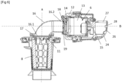
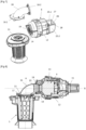
- THE figures 1 to 7 represent a vacuum cleaner 2, and more particularly a portable vacuum cleaner, comprising a main body 3 equipped with a gripping handle 4, a waste separation device 5 mounted removably on the main body 3, and a suction device 6 housed in the main body 3.
- the waste separation device 5 is advantageously of the cyclonic type, and notably comprises a waste storage container 7, and a separator filter 8 housed in the waste storage container 7.
- the waste storage container 7 more particularly comprises a air intake opening 9 and an air outlet 11.
- the suction device 6 comprises a motor casing 12 and a motorized fan 13, also called a suction motor, arranged in the motor casing 12.
- the motorized fan 13 comprises a fan and a motor electric configured to rotate the fan.
- the waste separation device 5 extends along a first axis of extension A
- the motorized fan 13 extends along a second axis of extension B which is transverse to the first axis of extension A, and advantageously perpendicular to the first axis of extension A.
- the suction device 6 comprises an air inlet orifice 14 and an air discharge orifice 15 which are advantageously provided on the motor casing 12.
- the air outlet orifice 11 of the waste separation device 5 and the air inlet orifice 14 of the suction device 6 have passage sections different. According to the embodiment shown on the figures 1 to 7 , the passage section of the air outlet orifice 11 is greater than the passage section of the air inlet orifice 14.
- the vacuum cleaner 2 further comprises an energy storage element 10, such as a rechargeable battery, configured to electrically power the motorized fan 13.
- the energy storage element 10 is advantageously housed in the main body 3 , and for example in the gripping handle 4.
- the vacuum cleaner 2 further comprises a connecting tube 16 which fluidly connects the air inlet orifice 14 of the suction device 6 to the air outlet orifice 11 of the waste separation device 5.
- the connecting tube 16 is in one piece.
- the connecting tube 16 is bent, and has a first end 16.1 which is fluidly connected to the air outlet orifice 11 of the waste separation device 5 and which has a passage section corresponding substantially to the passage section of the air outlet orifice 11, and a second end 16.2 which is fluidly connected to the air inlet orifice 14 of the suction device 6 and which has a passage section corresponding substantially to the passage section from the air inlet port 14.
- the connecting pipe 16 has a passage section which evolves continuously from the first end 16.1 to the second end 16.2, and therefore from the air outlet 11 of the waste separation device 5 until to the air inlet port 14 of the suction device 6.
- the connecting tube 16 comprises a mounting part 17 which extends around the first end 16.1 and which is fixed to the main body 3, and also a fixing part 18 which extends around the second end 16.2 and which is fixed to the motor housing 12 of the suction device 6.
- the vacuum cleaner 2 also includes a protective grid 19 which is located upstream of the motorized fan 13 so as to prevent access by a user to the active parts of the motorized fan 13, in particular when the waste separation device 5 is removed .
- the protective grid 19 is integrated into the motor casing 12, and is advantageously located at the level of the air inlet orifice 14 of the suction device 6.
- the main body 3 further comprises an air suction conduit 21 to which the air intake opening 9 of the waste separation device 5 is fluidly connected, and an air exhaust conduit 22 which connects fluidly the air discharge orifice 15 of the suction device 6 to air evacuation openings 23 provided on the main body 3.
- the motorized fan 13 is more particularly configured to generate an air flow through the air suction duct 21, the air outlet orifice 11, the connecting tube 16 and the orifice air inlet 14.
- the air flow generated by the motorized fan 13 is rejected towards the outside of the vacuum cleaner 2 via the air exhaust duct 22 and the air exhaust openings 23.
- the air exhaust duct 22 comprises a flow guide element 24 which is fixed to the motor casing 12 and into which the air discharge orifice 15 of the suction device 6 opens.
- flow guidance 24 is more particularly configured to channel and guide the air flow leaving the air delivery orifice 15 towards the air exhaust openings 23.
- the flow guide element 24 comprises two side walls 25.1, 25.2 and a guide wall 26 which interconnects the two side walls 25.1, 25.2.
- the guide wall 26 is curved and is located opposite the air discharge orifice 15.
- the flow guide element 24 more particularly comprises an outlet opening 27 which is oriented substantially perpendicular to the second extension axis B of the motorized fan 13 and towards the air exhaust openings 23.
- the flow guide element 24 may optionally comprise a plurality of guide fins 28 provided on an interior surface of the wall guide 26.
- the suction device 6, the connecting tube 16 and the flow guide element 24 advantageously form a subassembly which can be assembled prior to its attachment to the main body 3.
- the vacuum cleaner 2 further comprises a sound absorption element 29 positioned in the air exhaust duct 22.
- the sound absorption element 29 can be positioned downstream of the flow guide element 24 or still in the flow guide element 24.
- the sound absorption element 29 is advantageously made of porous material, and can for example be an acoustic foam.
- the motorized fan 13 When the motorized fan 13 is electrically powered, it establishes a depression in particular in the waste separation device 5 so that air and waste are sucked in by the air suction conduit 21.
- the air loaded with waste then enters the waste storage container 7 via the air intake opening 9 which can for example open tangentially into the waste storage container 7. The air is thus rotated and the waste are centrifuged outwards and this waste is collected by the waste storage container 7.
- the air flow then flows successively through the air outlet orifice 11, the connecting tube 16 and the air inlet orifice 14 of the suction device 6, without encountering any sudden change in section due to the specific configuration of the connecting pipe 16.
- Such a configuration of the connecting pipe thus significantly reduces the pressure losses generated within the connecting pipe 16, which improves the aeraulic performance of the vacuum cleaner 2.
- the air flow flows through the air discharge port 15 and along the air exhaust duct 22 before escaping through the sound absorption element 29 in direction of the evacuation openings 23.
- THE figures 8 And 9 represent a vacuum cleaner according to a second embodiment of the invention which differs from that represented on the figures 1 to 7 essentially in that the protective grid 19 is integrated into the connecting tube 16 and is located near the second end 16.2 of the connecting tube 16.
Landscapes
- Engineering & Computer Science (AREA)
- Mechanical Engineering (AREA)
- Filters For Electric Vacuum Cleaners (AREA)
- Electric Vacuum Cleaner (AREA)
- Refuse Collection And Transfer (AREA)
Claims (15)
- Staubsauger (2), umfassend eine Abfalltrennvorrichtung (5), die eine Luftauslassöffnung (11) aufweist, eine Saugvorrichtung (6), die eine Lufteinlassöffnung (14) und ein Motorgebläse (13) aufweist, und einen Verbindungsstutzen (16), der die Lufteinlassöffnung (14) der Saugvorrichtung (6) mit der Luftauslassöffnung (11) der Abfalltrennvorrichtung (5) fluidisch verbindet, wobei das Motorgebläse (13) dazu konfiguriert ist, einen Luftstrom durch die Auslassöffnung (11), den Verbindungsstutzen (16) und die Lufteinlassöffnung (14) zu erzeugen, dadurch gekennzeichnet, dass der Verbindungsstutzen (16) gekrümmt ist und sich kontinuierlich von der Auslassöffnung (11) der Abfalltrennvorrichtung (5) bis zur Lufteinlassöffnung (14) der Absaugvorrichtung (6) erstreckt, und dass der Verbindungsstutzen (16) einen Durchgangsquerschnitt aufweist, der sich kontinuierlich von der Auslassöffnung (11) der Abfalltrennvorrichtung (5) bis zur Lufteinlassöffnung (14) der Saugvorrichtung (6) entwickelt.
- Staubsauger (2) nach Anspruch 1, wobei die Auslassöffnung (11) der Abfalltrennvorrichtung (5) und die Lufteinlassöffnung (14) der Saugvorrichtung (6) unterschiedliche Durchgangsquerschnitte aufweisen.
- Staubsauger (2) nach Anspruch 2, wobei ein Durchgangsquerschnitt der Luftauslassöffnung (11) der Abfalltrennvorrichtung (5) größer ist als ein Durchgangsquerschnitt der Lufteinlassöffnung (14) der Saugvorrichtung (6).
- Staubsauger (2) nach einem der Ansprüche 1 bis 3, wobei die Saugvorrichtung (6) ein Motorgehäuse (12) aufweist, in dem das Motorgebläse (13) angeordnet ist, wobei das Motorgehäuse (12) die Lufteinlassöffnung (14) aufweist.
- Staubsauger (2) nach Anspruch 4, wobei der Verbindungsstutzen (16) einen Befestigungsteil (18) aufweist, der am Motorgehäuse (12) der Saugvorrichtung (6) befestigt ist.
- Staubsauger (2) nach einem der Ansprüche 1 bis 5, der ein Schutzgitter (19) aufweist, das stromaufwärts des Motorgebläses (13) angeordnet ist, so dass ein Zugang zum Motorgebläse (13) verhindert wird.
- Staubsauger (2) nach Anspruch 6, wobei das Schutzgitter (19) in den Verbindungsstutzen (16) integriert ist.
- Staubsauger (2) nach Anspruch 6 in Verbindung mit Anspruch 5, wobei das Schutzgitter (19) in das Motorgehäuse (12) integriert ist.
- Staubsauger (2) nach einem der Ansprüche 1 bis 8, wobei der Verbindungsstutzen (16) ein erstes Ende (16.1), das mit der Luftauslassöffnung (11) der Abfalltrennvorrichtung (5) fluidisch verbunden ist und das einen im Wesentlichen dem Durchgangsquerschnitt der Luftauslassöffnung (11) entsprechenden Durchgangsquerschnitt aufweist, und ein zweites Ende (16.2), das mit der Lufteinlassöffnung (14) der Saugvorrichtung (6) fluidisch verbunden ist und das einen im Wesentlichen dem Durchgangsquerschnitt der Lufteinlassöffnung (14) entsprechenden Durchgangsquerschnitt aufweist.
- Staubsauger (2) nach einem der Ansprüche 1 bis 9, wobei sich die Abfalltrennvorrichtung (5) entlang einer ersten Erstreckungsachse (A) erstreckt und das Motorgebläse (13) sich entlang einer zweiten Erstreckungsachse (B) erstreckt, die quer zur ersten Erstreckungsachse (A) verläuft.
- Staubsauger (2) nach einem der Ansprüche 1 bis 10, wobei die Abfalltrennvorrichtung (5) vom Zyklontyp ist.
- Staubsauger (2) nach einem der Ansprüche 1 bis 11, wobei der Verbindungsstutzen (16) einstückig ist.
- Staubsauger (2) nach einem der Ansprüche 1 bis 12, der mindestens eine Luftaustrittsöffnung (23) aufweist, durch die der von dem Motorgebläse (13) erzeugte Luftstrom aus dem Staubsauger (2) nach außen abgeführt wird, und einen Luftaustrittskanal (22), der eine Luftausstoßöffnung (15) der Saugvorrichtung (6) mit der mindestens einen Luftaustrittsöffnung (23) fluidisch verbindet.
- Staubsauger (2) nach Anspruch 13, wobei der Luftaustrittskanal (22) ein Strömungsleitelement (24) aufweist, in das die Luftausstoßöffnung (15) der Saugvorrichtung (6) mündet, wobei das Strömungsleitelement (24) dazu konfiguriert ist, den aus der Luftausstoßöffnung (15) austretenden Luftstrom zu der mindestens einen Luftaustrittsöffnung (23) zu kanalisieren und zu leiten.
- Staubsauger (2) nach einem der Ansprüche 1 bis 14, wobei es sich um einen tragbaren Staubsauger handelt, der elektrisch über eine Batterie versorgt wird.
Priority Applications (1)
| Application Number | Priority Date | Filing Date | Title |
|---|---|---|---|
| EP24184774.8A EP4410167A3 (de) | 2019-02-21 | 2020-02-18 | Staubsauger mit einem verbindungsrohr |
Applications Claiming Priority (1)
| Application Number | Priority Date | Filing Date | Title |
|---|---|---|---|
| FR1901774A FR3092979B1 (fr) | 2019-02-21 | 2019-02-21 | Aspirateur équipé d’une tubulure de liaison |
Related Child Applications (2)
| Application Number | Title | Priority Date | Filing Date |
|---|---|---|---|
| EP24184774.8A Division EP4410167A3 (de) | 2019-02-21 | 2020-02-18 | Staubsauger mit einem verbindungsrohr |
| EP24184774.8A Division-Into EP4410167A3 (de) | 2019-02-21 | 2020-02-18 | Staubsauger mit einem verbindungsrohr |
Publications (3)
| Publication Number | Publication Date |
|---|---|
| EP3698694A1 EP3698694A1 (de) | 2020-08-26 |
| EP3698694C0 EP3698694C0 (de) | 2024-08-07 |
| EP3698694B1 true EP3698694B1 (de) | 2024-08-07 |
Family
ID=67002025
Family Applications (2)
| Application Number | Title | Priority Date | Filing Date |
|---|---|---|---|
| EP24184774.8A Pending EP4410167A3 (de) | 2019-02-21 | 2020-02-18 | Staubsauger mit einem verbindungsrohr |
| EP20158096.6A Active EP3698694B1 (de) | 2019-02-21 | 2020-02-18 | Staubsauger, der mit einem verbindungschlauch ausgestattet ist |
Family Applications Before (1)
| Application Number | Title | Priority Date | Filing Date |
|---|---|---|---|
| EP24184774.8A Pending EP4410167A3 (de) | 2019-02-21 | 2020-02-18 | Staubsauger mit einem verbindungsrohr |
Country Status (3)
| Country | Link |
|---|---|
| EP (2) | EP4410167A3 (de) |
| CN (1) | CN111588303B (de) |
| FR (1) | FR3092979B1 (de) |
Families Citing this family (1)
| Publication number | Priority date | Publication date | Assignee | Title |
|---|---|---|---|---|
| FR3126181B1 (fr) * | 2021-08-17 | 2023-08-04 | Seb Sa | Aspirateur portatif équipé d’une paroi d’absorption acoustique |
Family Cites Families (18)
| Publication number | Priority date | Publication date | Assignee | Title |
|---|---|---|---|---|
| US3898068A (en) * | 1974-05-31 | 1975-08-05 | John A Mcneil | Cyclonic separator |
| AU5921496A (en) * | 1995-10-04 | 1997-04-28 | Pro-Team, Inc. | Cyclonic vacuum cleaner |
| JP2004129783A (ja) * | 2002-10-09 | 2004-04-30 | Toshiba Tec Corp | 電気掃除機 |
| FR2847148B1 (fr) * | 2002-11-19 | 2005-04-29 | Gabriel Barsacq | Intercepteur/recuperateur, fixe sur la poignee du flexible d'aspiration d'un systeme d'aspiration centralisee, integre dans la construction |
| KR100607439B1 (ko) * | 2004-08-23 | 2006-08-02 | 삼성광주전자 주식회사 | 사이클론 집진장치 |
| US7645309B2 (en) * | 2004-12-27 | 2010-01-12 | Lg Electronics Inc. | Dust collection unit and vacuum cleaner with the same |
| SE531125C2 (sv) * | 2007-01-19 | 2008-12-23 | Electrolux Ab | Förbättringar med avseende på luftströmningsförluster i en dammsugare |
| CN201290640Y (zh) * | 2008-10-24 | 2009-08-19 | 金莱克电气股份有限公司 | 吸尘器电机消音结构 |
| WO2010102394A1 (en) * | 2009-03-11 | 2010-09-16 | G.B.D. Corp. | Hand vacuum cleaner with removable dirt chamber |
| CN203506614U (zh) * | 2013-05-15 | 2014-04-02 | 安徽理工大学 | 一种旋风吸尘器 |
| CN203670244U (zh) * | 2014-01-14 | 2014-06-25 | 深圳市银星智能科技股份有限公司 | 一种风机组件和装有该风机组件的吸尘装置 |
| US10791889B2 (en) * | 2016-01-08 | 2020-10-06 | Omachron Intellectual Property Inc. | Hand carryable surface cleaning apparatus |
| FR3046046B1 (fr) * | 2015-12-23 | 2017-12-22 | Seb Sa | Geometrie d'un circuit aeraulique pour un aspirateur a main |
| CN105982622B (zh) * | 2016-04-14 | 2019-08-06 | 北京小米移动软件有限公司 | 自动清洁设备的风道结构、风路结构和自动清洁设备 |
| JP6609538B2 (ja) * | 2016-11-18 | 2019-11-20 | 日立グローバルライフソリューションズ株式会社 | 電動送風機及びこれを有する電気掃除機 |
| CN107212824A (zh) * | 2017-05-15 | 2017-09-29 | 意诺科技有限公司 | 一种清洁设备以及清洁设备的风道结构 |
| CN107137014A (zh) * | 2017-05-15 | 2017-09-08 | 意诺科技有限公司 | 一种风道结构、风路结构及自动清洁设备 |
| DE102017209158A1 (de) * | 2017-05-31 | 2018-12-06 | BSH Hausgeräte GmbH | Einfach entleerbarer in der Hand gehaltenen akkubetriebenen Staubsauger |
-
2019
- 2019-02-21 FR FR1901774A patent/FR3092979B1/fr active Active
-
2020
- 2020-02-18 EP EP24184774.8A patent/EP4410167A3/de active Pending
- 2020-02-18 EP EP20158096.6A patent/EP3698694B1/de active Active
- 2020-02-20 CN CN202010104910.XA patent/CN111588303B/zh not_active Expired - Fee Related
Also Published As
| Publication number | Publication date |
|---|---|
| EP3698694C0 (de) | 2024-08-07 |
| EP4410167A2 (de) | 2024-08-07 |
| FR3092979A1 (fr) | 2020-08-28 |
| EP4410167A3 (de) | 2024-10-16 |
| EP3698694A1 (de) | 2020-08-26 |
| CN111588303A (zh) | 2020-08-28 |
| FR3092979B1 (fr) | 2021-05-28 |
| CN111588303B (zh) | 2023-07-21 |
Similar Documents
| Publication | Publication Date | Title |
|---|---|---|
| EP3184011B1 (de) | Geometrie eines luftkreislaufs für einen handsauger | |
| WO2021160671A1 (fr) | Aspirateur portatif equipe d'un carter principal comportant une premiere et une deuxieme parties de carter distinctes | |
| EP1404203B1 (de) | Selbständiger hochwirksamer staubsauger | |
| EP3954261B1 (de) | Tragbarer staubsauger, der mit einem abnehmbaren filter ausgestattet ist | |
| FR2855389A1 (fr) | Collecteur de poussiere a cyclone et ensemble formant poignee pour un aspirateur | |
| EP4241640B1 (de) | Tragbarer staubsauger, der mit einem abnehmbaren filter ausgestattet ist | |
| EP3996563B1 (de) | Tragbarer staubsauger und staubsauger mit einem tragbaren staubsauger | |
| EP4056087B1 (de) | Hausstaubsauger, der mit einem schalldämpfenden hohlraum ausgestattet ist | |
| EP3662803B1 (de) | Hausstaubsauger, der mit einem schallabsorptionselement ausgestattet ist | |
| EP4410167A2 (de) | Staubsauger mit einem verbindungsrohr | |
| EP4385377B1 (de) | Absaugvorrichtung für haushaltsstaubsauger | |
| EP3698695B1 (de) | Besenstaubsauger, der mit einem hauptkorpus ausgestattet ist, der aus einer ersten und einer zweiten halbschale gebildet ist | |
| EP3698699B1 (de) | Staubsauger mit einer spannvorrichtung für einen abfallvorratsbehälter | |
| EP4385376B1 (de) | Absaugvorrichtung für haushaltsstaubsauger | |
| WO2023021254A1 (fr) | Aspirateur portatif équipé d'une paroi d'absorption acoustique | |
| EP4304431B1 (de) | Motorisierte basis für ein gerät zur zubereitung von lebensmitteln mit geräuscharmer entlüftung | |
| FR3119531A1 (fr) | Ensemble d’aspiration de type traineau équipé d’un dispositif de séparation cyclonique |
Legal Events
| Date | Code | Title | Description |
|---|---|---|---|
| PUAI | Public reference made under article 153(3) epc to a published international application that has entered the european phase |
Free format text: ORIGINAL CODE: 0009012 |
|
| STAA | Information on the status of an ep patent application or granted ep patent |
Free format text: STATUS: THE APPLICATION HAS BEEN PUBLISHED |
|
| AK | Designated contracting states |
Kind code of ref document: A1 Designated state(s): AL AT BE BG CH CY CZ DE DK EE ES FI FR GB GR HR HU IE IS IT LI LT LU LV MC MK MT NL NO PL PT RO RS SE SI SK SM TR |
|
| AX | Request for extension of the european patent |
Extension state: BA ME |
|
| STAA | Information on the status of an ep patent application or granted ep patent |
Free format text: STATUS: REQUEST FOR EXAMINATION WAS MADE |
|
| 17P | Request for examination filed |
Effective date: 20210219 |
|
| RBV | Designated contracting states (corrected) |
Designated state(s): AL AT BE BG CH CY CZ DE DK EE ES FI FR GB GR HR HU IE IS IT LI LT LU LV MC MK MT NL NO PL PT RO RS SE SI SK SM TR |
|
| GRAP | Despatch of communication of intention to grant a patent |
Free format text: ORIGINAL CODE: EPIDOSNIGR1 |
|
| STAA | Information on the status of an ep patent application or granted ep patent |
Free format text: STATUS: GRANT OF PATENT IS INTENDED |
|
| INTG | Intention to grant announced |
Effective date: 20240227 |
|
| GRAS | Grant fee paid |
Free format text: ORIGINAL CODE: EPIDOSNIGR3 |
|
| GRAA | (expected) grant |
Free format text: ORIGINAL CODE: 0009210 |
|
| STAA | Information on the status of an ep patent application or granted ep patent |
Free format text: STATUS: THE PATENT HAS BEEN GRANTED |
|
| AK | Designated contracting states |
Kind code of ref document: B1 Designated state(s): AL AT BE BG CH CY CZ DE DK EE ES FI FR GB GR HR HU IE IS IT LI LT LU LV MC MK MT NL NO PL PT RO RS SE SI SK SM TR |
|
| REG | Reference to a national code |
Ref country code: GB Ref legal event code: FG4D Free format text: NOT ENGLISH |
|
| REG | Reference to a national code |
Ref country code: CH Ref legal event code: EP |
|
| REG | Reference to a national code |
Ref country code: IE Ref legal event code: FG4D Free format text: LANGUAGE OF EP DOCUMENT: FRENCH |
|
| REG | Reference to a national code |
Ref country code: DE Ref legal event code: R096 Ref document number: 602020035145 Country of ref document: DE |
|
| U01 | Request for unitary effect filed |
Effective date: 20240905 |
|
| U07 | Unitary effect registered |
Designated state(s): AT BE BG DE DK EE FI FR IT LT LU LV MT NL PT RO SE SI Effective date: 20240919 |
|
| PG25 | Lapsed in a contracting state [announced via postgrant information from national office to epo] |
Ref country code: NO Free format text: LAPSE BECAUSE OF FAILURE TO SUBMIT A TRANSLATION OF THE DESCRIPTION OR TO PAY THE FEE WITHIN THE PRESCRIBED TIME-LIMIT Effective date: 20241107 |
|
| PG25 | Lapsed in a contracting state [announced via postgrant information from national office to epo] |
Ref country code: PL Free format text: LAPSE BECAUSE OF FAILURE TO SUBMIT A TRANSLATION OF THE DESCRIPTION OR TO PAY THE FEE WITHIN THE PRESCRIBED TIME-LIMIT Effective date: 20240807 Ref country code: GR Free format text: LAPSE BECAUSE OF FAILURE TO SUBMIT A TRANSLATION OF THE DESCRIPTION OR TO PAY THE FEE WITHIN THE PRESCRIBED TIME-LIMIT Effective date: 20241108 |
|
| PG25 | Lapsed in a contracting state [announced via postgrant information from national office to epo] |
Ref country code: IS Free format text: LAPSE BECAUSE OF FAILURE TO SUBMIT A TRANSLATION OF THE DESCRIPTION OR TO PAY THE FEE WITHIN THE PRESCRIBED TIME-LIMIT Effective date: 20241207 |
|
| PG25 | Lapsed in a contracting state [announced via postgrant information from national office to epo] |
Ref country code: HR Free format text: LAPSE BECAUSE OF FAILURE TO SUBMIT A TRANSLATION OF THE DESCRIPTION OR TO PAY THE FEE WITHIN THE PRESCRIBED TIME-LIMIT Effective date: 20240807 |
|
| PG25 | Lapsed in a contracting state [announced via postgrant information from national office to epo] |
Ref country code: ES Free format text: LAPSE BECAUSE OF FAILURE TO SUBMIT A TRANSLATION OF THE DESCRIPTION OR TO PAY THE FEE WITHIN THE PRESCRIBED TIME-LIMIT Effective date: 20240807 Ref country code: RS Free format text: LAPSE BECAUSE OF FAILURE TO SUBMIT A TRANSLATION OF THE DESCRIPTION OR TO PAY THE FEE WITHIN THE PRESCRIBED TIME-LIMIT Effective date: 20241107 |
|
| PG25 | Lapsed in a contracting state [announced via postgrant information from national office to epo] |
Ref country code: RS Free format text: LAPSE BECAUSE OF FAILURE TO SUBMIT A TRANSLATION OF THE DESCRIPTION OR TO PAY THE FEE WITHIN THE PRESCRIBED TIME-LIMIT Effective date: 20241107 Ref country code: PL Free format text: LAPSE BECAUSE OF FAILURE TO SUBMIT A TRANSLATION OF THE DESCRIPTION OR TO PAY THE FEE WITHIN THE PRESCRIBED TIME-LIMIT Effective date: 20240807 Ref country code: NO Free format text: LAPSE BECAUSE OF FAILURE TO SUBMIT A TRANSLATION OF THE DESCRIPTION OR TO PAY THE FEE WITHIN THE PRESCRIBED TIME-LIMIT Effective date: 20241107 Ref country code: IS Free format text: LAPSE BECAUSE OF FAILURE TO SUBMIT A TRANSLATION OF THE DESCRIPTION OR TO PAY THE FEE WITHIN THE PRESCRIBED TIME-LIMIT Effective date: 20241207 Ref country code: HR Free format text: LAPSE BECAUSE OF FAILURE TO SUBMIT A TRANSLATION OF THE DESCRIPTION OR TO PAY THE FEE WITHIN THE PRESCRIBED TIME-LIMIT Effective date: 20240807 Ref country code: GR Free format text: LAPSE BECAUSE OF FAILURE TO SUBMIT A TRANSLATION OF THE DESCRIPTION OR TO PAY THE FEE WITHIN THE PRESCRIBED TIME-LIMIT Effective date: 20241108 Ref country code: ES Free format text: LAPSE BECAUSE OF FAILURE TO SUBMIT A TRANSLATION OF THE DESCRIPTION OR TO PAY THE FEE WITHIN THE PRESCRIBED TIME-LIMIT Effective date: 20240807 |
|
| U20 | Renewal fee for the european patent with unitary effect paid |
Year of fee payment: 6 Effective date: 20250129 |
|
| PG25 | Lapsed in a contracting state [announced via postgrant information from national office to epo] |
Ref country code: SM Free format text: LAPSE BECAUSE OF FAILURE TO SUBMIT A TRANSLATION OF THE DESCRIPTION OR TO PAY THE FEE WITHIN THE PRESCRIBED TIME-LIMIT Effective date: 20240807 |
|
| PG25 | Lapsed in a contracting state [announced via postgrant information from national office to epo] |
Ref country code: CZ Free format text: LAPSE BECAUSE OF FAILURE TO SUBMIT A TRANSLATION OF THE DESCRIPTION OR TO PAY THE FEE WITHIN THE PRESCRIBED TIME-LIMIT Effective date: 20240807 |
|
| PG25 | Lapsed in a contracting state [announced via postgrant information from national office to epo] |
Ref country code: SK Free format text: LAPSE BECAUSE OF FAILURE TO SUBMIT A TRANSLATION OF THE DESCRIPTION OR TO PAY THE FEE WITHIN THE PRESCRIBED TIME-LIMIT Effective date: 20240807 |
|
| PLBE | No opposition filed within time limit |
Free format text: ORIGINAL CODE: 0009261 |
|
| STAA | Information on the status of an ep patent application or granted ep patent |
Free format text: STATUS: NO OPPOSITION FILED WITHIN TIME LIMIT |
|
| 26N | No opposition filed |
Effective date: 20250508 |
|
| PG25 | Lapsed in a contracting state [announced via postgrant information from national office to epo] |
Ref country code: MC Free format text: LAPSE BECAUSE OF FAILURE TO SUBMIT A TRANSLATION OF THE DESCRIPTION OR TO PAY THE FEE WITHIN THE PRESCRIBED TIME-LIMIT Effective date: 20240807 |
|
| REG | Reference to a national code |
Ref country code: CH Ref legal event code: PL |
|
| PG25 | Lapsed in a contracting state [announced via postgrant information from national office to epo] |
Ref country code: CH Free format text: LAPSE BECAUSE OF NON-PAYMENT OF DUE FEES Effective date: 20250228 |
|
| PG25 | Lapsed in a contracting state [announced via postgrant information from national office to epo] |
Ref country code: IE Free format text: LAPSE BECAUSE OF NON-PAYMENT OF DUE FEES Effective date: 20250218 |
|
| U20 | Renewal fee for the european patent with unitary effect paid |
Year of fee payment: 7 Effective date: 20260121 |
|
| PGFP | Annual fee paid to national office [announced via postgrant information from national office to epo] |
Ref country code: GB Payment date: 20260219 Year of fee payment: 7 |