EP3698906A1 - Porte-outil et support d'outil - Google Patents
Porte-outil et support d'outil Download PDFInfo
- Publication number
- EP3698906A1 EP3698906A1 EP20157964.6A EP20157964A EP3698906A1 EP 3698906 A1 EP3698906 A1 EP 3698906A1 EP 20157964 A EP20157964 A EP 20157964A EP 3698906 A1 EP3698906 A1 EP 3698906A1
- Authority
- EP
- European Patent Office
- Prior art keywords
- fixing
- tool holder
- carrier
- tool
- wedge
- Prior art date
- Legal status (The legal status is an assumption and is not a legal conclusion. Google has not performed a legal analysis and makes no representation as to the accuracy of the status listed.)
- Withdrawn
Links
- 238000003780 insertion Methods 0.000 claims abstract description 26
- 230000037431 insertion Effects 0.000 claims abstract description 26
- 238000006073 displacement reaction Methods 0.000 claims description 14
- 230000001154 acute effect Effects 0.000 claims description 6
- 230000006835 compression Effects 0.000 description 6
- 238000007906 compression Methods 0.000 description 6
- 230000002349 favourable effect Effects 0.000 description 6
- 239000000969 carrier Substances 0.000 description 4
- 238000003754 machining Methods 0.000 description 4
- 230000000295 complement effect Effects 0.000 description 1
- 230000000694 effects Effects 0.000 description 1
- 238000009434 installation Methods 0.000 description 1
- 230000003993 interaction Effects 0.000 description 1
- 238000000034 method Methods 0.000 description 1
- 230000000149 penetrating effect Effects 0.000 description 1
- 230000006641 stabilisation Effects 0.000 description 1
- 238000011105 stabilization Methods 0.000 description 1
- 208000008918 voyeurism Diseases 0.000 description 1
Images


Classifications
-
- B—PERFORMING OPERATIONS; TRANSPORTING
- B23—MACHINE TOOLS; METAL-WORKING NOT OTHERWISE PROVIDED FOR
- B23B—TURNING; BORING
- B23B29/00—Holders for non-rotary cutting tools; Boring bars or boring heads; Accessories for tool holders
- B23B29/04—Tool holders for a single cutting tool
- B23B29/12—Special arrangements on tool holders
- B23B29/20—Special arrangements on tool holders for placing same by shanks in sleeves of a turret
-
- B—PERFORMING OPERATIONS; TRANSPORTING
- B23—MACHINE TOOLS; METAL-WORKING NOT OTHERWISE PROVIDED FOR
- B23Q—DETAILS, COMPONENTS, OR ACCESSORIES FOR MACHINE TOOLS, e.g. ARRANGEMENTS FOR COPYING OR CONTROLLING; MACHINE TOOLS IN GENERAL CHARACTERISED BY THE CONSTRUCTION OF PARTICULAR DETAILS OR COMPONENTS; COMBINATIONS OR ASSOCIATIONS OF METAL-WORKING MACHINES, NOT DIRECTED TO A PARTICULAR RESULT
- B23Q1/00—Members which are comprised in the general build-up of a form of machine, particularly relatively large fixed members
- B23Q1/25—Movable or adjustable work or tool supports
- B23Q1/26—Movable or adjustable work or tool supports characterised by constructional features relating to the co-operation of relatively movable members; Means for preventing relative movement of such members
-
- B—PERFORMING OPERATIONS; TRANSPORTING
- B23—MACHINE TOOLS; METAL-WORKING NOT OTHERWISE PROVIDED FOR
- B23Q—DETAILS, COMPONENTS, OR ACCESSORIES FOR MACHINE TOOLS, e.g. ARRANGEMENTS FOR COPYING OR CONTROLLING; MACHINE TOOLS IN GENERAL CHARACTERISED BY THE CONSTRUCTION OF PARTICULAR DETAILS OR COMPONENTS; COMBINATIONS OR ASSOCIATIONS OF METAL-WORKING MACHINES, NOT DIRECTED TO A PARTICULAR RESULT
- B23Q3/00—Devices holding, supporting, or positioning work or tools, of a kind normally removable from the machine
-
- B—PERFORMING OPERATIONS; TRANSPORTING
- B23—MACHINE TOOLS; METAL-WORKING NOT OTHERWISE PROVIDED FOR
- B23B—TURNING; BORING
- B23B29/00—Holders for non-rotary cutting tools; Boring bars or boring heads; Accessories for tool holders
- B23B29/04—Tool holders for a single cutting tool
- B23B29/046—Tool holders for a single cutting tool with an intermediary toolholder
-
- B—PERFORMING OPERATIONS; TRANSPORTING
- B23—MACHINE TOOLS; METAL-WORKING NOT OTHERWISE PROVIDED FOR
- B23Q—DETAILS, COMPONENTS, OR ACCESSORIES FOR MACHINE TOOLS, e.g. ARRANGEMENTS FOR COPYING OR CONTROLLING; MACHINE TOOLS IN GENERAL CHARACTERISED BY THE CONSTRUCTION OF PARTICULAR DETAILS OR COMPONENTS; COMBINATIONS OR ASSOCIATIONS OF METAL-WORKING MACHINES, NOT DIRECTED TO A PARTICULAR RESULT
- B23Q1/00—Members which are comprised in the general build-up of a form of machine, particularly relatively large fixed members
- B23Q1/25—Movable or adjustable work or tool supports
-
- B—PERFORMING OPERATIONS; TRANSPORTING
- B23—MACHINE TOOLS; METAL-WORKING NOT OTHERWISE PROVIDED FOR
- B23B—TURNING; BORING
- B23B2260/00—Details of constructional elements
- B23B2260/146—Wedges
Definitions
- the invention relates to a tool carrier of a machine tool, comprising a tool holder carrier with a receptacle extending into the tool holder carrier, into which a fixation body of a tool holder can be inserted by moving it in an insertion direction and, in an inserted state, by fixing it in the receptacle by a form-fitting element.
- the invention is therefore based on the object of improving a tool carrier of the type described in the introduction in such a way that the fixing body can be fixed as simply and quickly as possible.
- the form-fit element is a fixing wedge body which can be moved in the tool holder carrier in a direction of movement transverse to the insertion direction between a release position and a fixing position and in that the fixing wedge body in the fixing position has a wedge receptacle of the fixing body cooperates to fix it.
- the advantage of the solution according to the invention is that such a fixing wedge body can be moved in a simple manner and thus opens up the possibility of the fixing body in the fixing position by simply moving it between the release position and the fixing position and interacting with the wedge receptacle of the fixing body in the fixing position Establish or solve recording, it being possible to generate large forces for fixing the fixing body with a wedge body.
- the fixing wedge body could be movable on a curved path between the release position and the fixing position.
- a particularly simple operating option provides that the fixing wedge body can be moved linearly in the tool holder carrier and acts with a fixing wedge surface on a wedge surface of the wedge receptacle of the fixing body.
- the guide channel can basically run in different directions in the tool holder carrier.
- a particularly advantageous solution provides that the guide channel penetrates the receptacle transversely to the insertion direction, preferably penetrates it transversely to the insertion direction and thus opens up the possibility of moving the fixing wedge body guided in this between the fixing position and the release position.
- the fixing wedge body has a support surface on a side opposite the fixing wedge surface, with which it is guided in the guide channel, at least in the fixing position.
- a particularly favorable solution provides that the fixing wedge body is supported in the fixing position on both sides of the receptacle in the guide channel with its support surface, in which case in particular the guide channel penetrates the receptacle transversely to the insertion direction.
- the fixing wedge surface of the fixing wedge body runs in a plane which forms an acute angle with a guiding direction of the fixing wedge body movable in the guide channel, so that the fixing wedge surface runs obliquely to the guiding direction when the fixing wedge body is displaced in the guiding direction and thus can act in a simple manner on the fixing body, in particular the wedge surface of the fixing body, and can act on the fixing body with great forces in the fixing position.
- the fixing wedge body can be moved between the fixing position and the release position by means of a positioning unit and can be positioned both in the fixing position and the release position by means of the positioning unit.
- the positioning unit could be arranged directly next to the receptacle.
- the positioning unit is arranged on the tool holder carrier on a side facing away from a front side of the tool holder carrier facing the workpiece.
- a particularly simple and expedient solution provides that the positioning unit can be operated manually for moving the fixing wedge body between the fixing position and the release position and for fixing the fixing body in the fixing position.
- a solution that is easy to operate manually provides that the positioning unit has a bayonet structure, by means of which the fixing wedge body can be positioned both in the fixing position and in the release position.
- a bayonet structure opens up the possibility of clearly defining two positions arranged at a distance from one another in a displacement direction, one being assigned to the fixing position and one being assigned to the release position, so that the fixing wedge body can be fixed in these positions on the one hand and on the other can be shifted in a simple manner between these positions in order to quickly switch from the fixing position to the release position or the release position to the fixing position.
- the positioning unit is preferably designed such that it has a flange body with bayonet flanges which interact with a bayonet contour of a guide sleeve.
- the bayonet contour is designed so that it has two support surfaces arranged at a distance from one another in a displacement direction and rotated by an angle about an axis parallel to the displacement direction, these two support surfaces serving to define defined positions for the release position and essentially also the Specify the fixing position.
- the flange body is connected to the bayonet flanges with a centering body which is guided displaceably in the direction of displacement in the guide sleeve.
- the centering body and the fixing wedge body are preferably coupled in such a way that the fixing wedge body is displaced by moving the centering body in the guide sleeve and the fixing wedge body is positioned both in the release position and by fixing the centering body with the bayonet flanges of the bayonet structure can take place in a starting position for the fixing position.
- the fixing wedge body is adjustably coupled to the positioning unit, in particular to the centering body of the positioning unit.
- a particularly advantageous solution provides that the centering body is coupled to the fixing wedge body by means of an adjusting screw screwed to the centering body.
- the adjusting screw is screwed into the centering body.
- Such an adjusting screw thus makes it possible, at least in the fixing position, to carry out a relative positioning of the fixing wedge body relative to an initial position predetermined by the bayonet flanges and the one support surface.
- the positioning unit allows, for example, such an adjustment of the fixing body that it can initially be moved from the release position to the starting position for the fixing position without any significant effort, in which the fixing wedge body does not yet interact with the fixing body without play.
- the adjustment screw When the starting position for the fixing position defined by the bayonet flange and the support surface of the bayonet contour is reached, the adjustment screw now creates the possibility of moving the fixing wedge body until it hits the fixing body of the tool holder with a force that is a component in the insertion direction has, acts to move the fixing body into a defined end position in the receptacle and to hold it under force.
- a particularly favorable solution provides that the tool holder carrier has a support side on which the tool holder can be placed, in particular supported, in order to connect the tool holder to the tool holder carrier with the necessary stability.
- the tool holder carrier is provided on the support side with first form-locking elements which in particular extend transversely to a feed direction of the tool holder carrier.
- Such form-fit elements have the advantage that they are able to absorb forces in the feed direction.
- such a solution provides that the receptacle extends from the support side into the tool holder body, so that when the fixation body in the receptacle is acted upon by the fixation wedge body, the tool holder can be held in contact with force on the support side and thus the form-fit elements can also be force-acted upon the tool holder can interact.
- the invention relates to a tool holder for fixing to a tool carrier, in particular according to one or more of the preceding features, the tool holder having a fixing body which can be inserted into the receptacle of the tool carrier.
- the fixing body can be designed in the most varied of ways.
- the tool holder has a support body which can be placed with a support surface on the support side of the tool holder carrier.
- the fixing body extends away from the support body starting from the support side of the support body in order to be able to be brought into engagement with the receptacle in a simple manner.
- the support body is provided on the support side with second form-locking elements which are in engagement with first form-locking elements of the tool holder carrier when the tool holder is fixed on the tool holder carrier, these form-locking elements serving in particular to be used when machining a workpiece To absorb the tool and thus the tool holder acting and to be transmitted to the tool holder carrier forces, so that these forces are not transmitted to the tool holder carrier via the fixing body and the receptacle.
- the second form-locking elements in cooperation with the first form-locking elements, position the tool holder exactly relative to the tool holder carrier in a feed direction, in particular in the X feed direction of the tool carrier, because exact positioning in the X feed direction is required a machine tool, in particular a lathe, is decisive for the accuracy of the machining.
- the fixing body has a greater extent in the direction transverse to a direction of movement of the fixing wedge body than in the direction of movement.
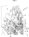
- the illustrated machine tool 10 in particular a lathe, preferably a multi-spindle lathe in the illustrated embodiment, comprises a machine frame designated as a whole by 12, on which, in the case of a multi-spindle machine, a spindle drum 14 is mounted about a spindle drum axis 16.
- the spindle drum 14 for its part carries a plurality of workpiece spindles 20 which are arranged around the spindle drum axis 16 at the same angular intervals relative to one another.
- the individual workpiece spindles 20 can be positioned in individual spindle stations in which the workpieces 22 rotating about spindle axes 24 and accommodated in the workpiece spindles 20 can be processed.
- tool carriers designated as a whole with 30 are arranged on the machine frame, which carry tool holders 32 with tools 34 held by these tool holders 32 ( Fig. 1 ).
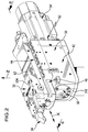
- the tool carriers 30 are designed so that they can be moved, for example, parallel to a Z-axis, i.e. parallel to the spindle axis 24 of the workpiece spindles 20, and in turn have a tool carrier base 42 on which a tool slide 44 by means of a slide guide 46 along a feed axis X is displaceably guided, the axis X preferably running radially to the respective spindle axis 24 of the workpiece spindle 20 in the respective spindle station.
- the tool carrier base 42 is provided with a slide drive 52 which has a drive motor 54 which, for example, has a motor that is arranged in the tool carrier base 42 and therefore in Fig. 2 Spindle drive 56 (not visible), by means of which the tool slide 44 is displaced in the X direction.
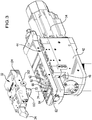
- the tool slide 44 in turn comprises a tool holder carrier 62 on which, as in FIG Fig. 2 and 3 shown, the tool holder 32 can be fixed with the tool 34.
- the tool holder body 62 is provided with a receptacle 64 which extends from a support side 66 of the tool holder carrier 62 for the tool holder 32 into the tool holder carrier 62 and serves to receive a fixing body 72 of the tool holder 32, the fixing body 72 in an insertion direction 74, which runs transversely to the support side 66, can be moved into the receptacle 64 and can be fixed in the receptacle 64, as will be described in detail below.
- the tool holder carrier 62 is provided in the area of its support side 66 and to the side of the receptacle 64 with first form-locking elements 82 which run transversely, preferably perpendicularly to the X direction and in the X direction on both sides of the receptacle 64 are provided in the support page 66.
- the first form-locking elements 82 have, as in FIG Fig. 6 shown, obliquely, in particular at an acute angle to the insertion direction 74 flank surfaces 84 and 86 and are preferably formed as grooves with their directions 88 parallel to each other, the directions 88 in turn running transversely, preferably perpendicular to the X direction.
- flank surfaces 84 and 86 preferably also run at the same distances relative to one another, so that the form-fit elements 82 have a constant cross-sectional shape transversely to the extension directions 88 over their extension in the extension direction 88.
- second form-fit elements 92 interact, which are designed to be complementary to the first form-fit elements 82 and have flank surfaces 94 and 96 that can be brought into contact with the flank surfaces 84 and 86 of the first form-fit elements 82 ( Fig. 6 ).
- These second form-locking elements 92 also extend with their directions 98 parallel to the directions 88 of the first form-locking elements and are arranged on a support side 102 of a support body 104 of the tool holder 32 ( Fig. 4 , 6th ).
- the form-fit elements 82, 92 are preferably designed as in FIG EP 1 514 623 A1 to which reference is made in full.
- the fixing body 72 is also arranged between the second form-locking elements 92 and, starting from the support side 102 of the support body 104, extends away from the latter.
- the first form-locking elements 82 and the second form-locking elements 92 interlock and fix the support body 104 relative to the tool holder carrier 62 against displacement in the X direction and at the same time also against a rotation about a possible axis of rotation running parallel to the insertion direction 74.
- the support body 104 of the tool holder 32 is already positively fixed against movement in the X direction by the form-fit elements 82 and 92, so that the first and second form-fit elements 82, 92 would only allow movement in the direction of the extension directions 88 and 98, respectively.
- the fixing body 72 is provided with a crosswise to the insertion direction 74 through the fixing body 72 through opening 112 provided ( Fig. 4 and Fig. 6 ), the opening 112 having a wedge surface 114 on a side opposite the support body 104, which extends transversely to the insertion direction 74.
- the wedge surface 114 interacts with a fixing wedge surface 116 of a fixing wedge body 118, which can be inserted into the opening 112.
- the fixing wedge body 118 is guided in a guide channel 122 in the tool holder carrier 62, the guide channel 122 running transversely to the receptacle 64, preferably perpendicular to the receptacle 64, in the tool holder carrier 62 and penetrating it and thus extending on both sides of the receptacle 64.
- the guide channel 122 defines a guide direction 124 along which the fixing wedge body 118 can be moved.
- the fixing wedge body 118 is designed in such a way that when the fixing wedge surface 116 acts on the wedge surface 114 of the fixing body 72 and acts on it with a force acting in the insertion direction 74, it comes with a support side 126 opposite the fixing wedge surface 116 on both sides of the receptacle 64 is supported in the guide channel 122 in support areas 128 adjoining the receptacle 64, so that the fixing wedge surface 116 acting on the wedge surface 114 lies between these two support areas 128 and there is thus the possibility, due to the mutual support of the fixing wedge body 118 with large forces on the wedge surface 114 to act.
- the shapes of the wedge surface 114 and the fixing wedge surface 116 are adapted to one another, so that they rest against one another over a large area and with the largest possible contact surface.
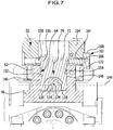
- the wedge surface 114 and the fixing wedge surface 116 run when they interact in planes 134 and 136 which coincide with one another and are parallel to one another, which on the one hand have an acute angle to the guide direction 124 and run to the insertion direction 74.
- the planes 134, 136 which are parallel to one another and coincide with the interaction of the wedge surface 114 and the fixing wedge surface 116, are preferably aligned in such a way that they enclose an acute angle with the guide direction 124 with increasing distance from one of the respective workpiece spindle 20 and thus the Workpiece facing front side 142 of the tool holder carrier 62 also extend with increasing distance from the support side 66 and also run parallel to a transverse direction 144 perpendicular to the insertion direction 74 and to the guide direction 124, the transverse direction 144 in turn preferably parallel to the support side 66 and preferably also parallel to the X -Direction is aligned ( Fig. 7 ).
- the fixing body 72 has transverse side surfaces 146 and 148 running parallel to the insertion direction 74, which abut the corresponding transverse guide surfaces 152 and 154 of the receptacle 64 and with these effect a transverse fixing of the fixing body 72 against movement in the transverse direction 144.
- the support body 104 and consequently also the tool holder 32 can be moved to a limited extent relative to the fixing body 72, for example, in the direction parallel to the transverse direction 144 and thus also parallel to the extension directions 88 and 98 of the first and second form-locking elements 82, 92, since this is T-shaped formed head 156 is held at least in the direction parallel to the transverse direction 144 with play in a receptacle 158 of the support body 104.
- an alignment screw 162 is also provided, which with its threaded section 164 in a parallel to Transverse direction 144 in the support body 104 engages threaded bore 166 and its head 168 can be placed on an alignment surface 172 of the tool holder carrier 62 in order to position the support body 104 precisely relative to the tool holder carrier 62, for example by bringing the transverse surface 148 into contact with the guide surface 154.
- the support body 104 is fixed relative to the tool holder carrier 62 by a frictional connection between the support side 102 of the support body 104 and the contact side 66 of the tool holder carrier 62, the force with which the support side 102 acts on the contact side 66 through the action of the fixing wedge body 118 on the fixing body 72 is produced.
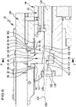
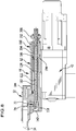
- the guide channel 122 extends from the receptacle 64 to a positioning unit 180 for the wedge body 118, whereby a sliding body 182 extending in continuation of the wedge body 118 runs in the guide channel 122, which connects the wedge body 118 with the positioning unit 180 ( Fig. 8 ).
- the support surfaces 194 and 196 are arranged rotated by 90 ° with respect to one another, for example.
- the guide sleeve 192 also forms guide surfaces 202 parallel to the guide direction 124, on which a centering body 204 adjoining the flange body 184 on a side opposite the fixing wedge body 118 is movably guided in the guiding direction 124, the centering body 204 fixed to the bayonet flanges 186 bearing flange body 184 is connected and the sliding body 182 encloses.
- the centering body 204 carries an actuating element 206 on a side of the guide sleeve 192 facing away from the flange body 184, which is designed, for example, as a manual actuating element and allows the centering body 204 together with the flange body 184 and the bayonet flanges 186 relative to the guide sleeve 192 and to rotate about an axis parallel to the guide direction 124 so that either the bayonet flanges 186 come to rest on the front support surfaces 194 or the rear support surfaces 196.
- a compression spring 208 is preferably also provided, which is on the one hand on a step 212 or a shoulder in the guide channel 122 and on the other hand acts on a collar 214 of the sliding body 182 and thus strives to move the sliding body 182 and with it the centering body 204 coupled to it from the fixing position in the direction of the release position.
- the sliding body 182 is connected to the centering body 204 via an adjusting screw 222 rotatably connected to it, in that an external thread 224 of the adjusting screw 222 engages an internal thread 226 of the centering body 204, and the sliding body 182 can thus be positioned in a defined manner relative to the centering body 204.
- the adjusting screw 222 allows an adjustable positioning of the fixing wedge body 118 relative to the starting position for the fixing position.
- the fixing body 72 of the tool holder 32 and the fixing wedge body 118, which is movably arranged on the tool holder carrier 62, with the positioning unit 180 thus form a quick-release clamping device for the tool carrier 30.
- This displacement of the centering body 204 simultaneously leads to a displacement of the fixing wedge body 118 such that it engages in the opening 112 of the fixing body 72 and acts with the fixing wedge surface 116 on the wedge surface 114 of the fixing body 72.
- the final bracing of the fixing body 72 in the receptacle 64 is carried out by turning the adjusting screw 222, which is rotatably connected to the sliding body 182, so that a slight further displacement of the fixing wedge body 118 leads to the bracing of the fixing body 72 in the receptacle 64, so that the Fixing wedge body 118 is supported on the one hand with the two support areas 128 in the guide channel 122 and on the other hand acts with the fixing wedge surface 116 on the wedge surface of the fixing body 72 and thus acts on it in the direction of the insertion direction 74 with a force which at the same time causes the form-locking elements 82 and 92 press against each other.
- the adjusting screw 222 is rotated again in the opposite direction, so that the tension between the fixing wedge body 118 and the fixing body 72 is released.
- the fixing wedge body 118 is then held in the release position by the compression spring 208.
- the quick-release device according to the invention thus enables the tool holder 32 to be fixed easily and quickly relative to the tool holder carrier 62, which, on the other hand, enables the tool holder 32 to be precisely positioned relative to the tool holder carrier 62.
- the assembly of the second tool holder 232 does not take place via the fixing body 72, but in a conventional manner by means of screws that can be screwed into the tool holder carrier 62 transversely to the support side 66.
- form-fit elements 242 are also provided, which interact with form-fit elements 244 that are also arranged on the second tool holder 232 ( Fig. 11 ).
- a driven tool holder designated as a whole by 252 can be mounted on the tool carrier 30 according to the invention, with this carrying a tool 254 (shown in dashed lines) that can be driven rotatably about an axis 256 ( Fig. 12 ).
- a drive motor designated as a whole by 258, is provided, which is flanged to a support body 264 of the third tool holder 252.
- the third tool holder 252 can be mounted on the tool carrier 30 conventionally and not with the quick-release clamping device according to the invention.
- the second and third exemplary embodiments show that both tool holders 32 designed according to the invention and conventionally designed tool holders 232, 252 using a conventional screw connection can be optionally mounted on the tool carrier 30 designed according to the invention.
Landscapes
- Engineering & Computer Science (AREA)
- Mechanical Engineering (AREA)
- Cutting Tools, Boring Holders, And Turrets (AREA)
Applications Claiming Priority (1)
| Application Number | Priority Date | Filing Date | Title |
|---|---|---|---|
| DE102019104686.6A DE102019104686A1 (de) | 2019-02-25 | 2019-02-25 | Werkzeugträger und Werkzeughalter |
Publications (1)
| Publication Number | Publication Date |
|---|---|
| EP3698906A1 true EP3698906A1 (fr) | 2020-08-26 |
Family
ID=69742639
Family Applications (1)
| Application Number | Title | Priority Date | Filing Date |
|---|---|---|---|
| EP20157964.6A Withdrawn EP3698906A1 (fr) | 2019-02-25 | 2020-02-18 | Porte-outil et support d'outil |
Country Status (4)
| Country | Link |
|---|---|
| US (1) | US20200269368A1 (fr) |
| EP (1) | EP3698906A1 (fr) |
| CN (1) | CN111604698A (fr) |
| DE (1) | DE102019104686A1 (fr) |
Cited By (1)
| Publication number | Priority date | Publication date | Assignee | Title |
|---|---|---|---|---|
| EP3771510A1 (fr) * | 2019-07-30 | 2021-02-03 | ESA Eppinger GmbH | Machine-outil dotée d'un porte-outil mobile, porte-outil et support d'outil correspondant |
Families Citing this family (3)
| Publication number | Priority date | Publication date | Assignee | Title |
|---|---|---|---|---|
| CH718197B1 (fr) * | 2020-12-21 | 2024-12-30 | Esco Sa | Unité d'usinage à tête rotative. |
| DE102022111683A1 (de) | 2021-12-23 | 2023-06-29 | Index-Werke Gmbh & Co. Kg Hahn & Tessky | Mehrspindelwerkzeugmaschine |
| EP4201585A1 (fr) | 2021-12-23 | 2023-06-28 | Index-Werke GmbH & Co. KG Hahn & Tessky | Machine-outil multibroche |
Citations (5)
| Publication number | Priority date | Publication date | Assignee | Title |
|---|---|---|---|---|
| DE7216193U (de) * | 1971-05-03 | 1972-11-23 | H Kaiser Ag | Ausdrehkopf |
| EP0416610A1 (fr) * | 1989-09-07 | 1991-03-13 | Traub AG | Porte-outil, notamment pour tours, avec porte-outil interchangeable |
| US5873682A (en) * | 1997-04-14 | 1999-02-23 | Koyo Corporation Of Usa | Pivoting tool holder |
| EP1514623A2 (fr) | 2003-09-11 | 2005-03-16 | Index-Werke Gmbh & Co. Kg Hahn & Tessky | Machine-outil et porte-outil associé |
| DE102010044968A1 (de) * | 2010-09-10 | 2012-03-15 | Sauter Feinmechanik Gmbh | Festlegevorrichtung |
Family Cites Families (36)
| Publication number | Priority date | Publication date | Assignee | Title |
|---|---|---|---|---|
| BE562267A (fr) * | 1956-11-23 | |||
| US3577819A (en) * | 1969-09-05 | 1971-05-04 | Hans Scheideler | Toolpost |
| FR2105346A5 (fr) * | 1970-09-02 | 1972-04-28 | Ernault Somua | |
| US3747946A (en) * | 1970-12-21 | 1973-07-24 | R Edens | Tool holders |
| DE2216542A1 (de) * | 1972-04-06 | 1973-10-11 | Battenfeld Wilfried | Schnellwechselhalter |
| DE2415004A1 (de) * | 1974-03-28 | 1975-10-09 | Wilfried Battenfeld | Voreinstellbarer schnellwechselstahlhalter mit feinverstellung in zwei koordinaten fuer drehmaschinen |
| US3988944A (en) * | 1974-04-01 | 1976-11-02 | Klasing Hand Brake Co. | Quick-release mechanism for a railway car hand brake of the non-spin type |
| US3918332A (en) * | 1974-06-10 | 1975-11-11 | Savarian F Lemanski | Selectively wedge clamping tool holder |
| US3911767A (en) * | 1974-12-30 | 1975-10-14 | Lester Alvin Myers | Quick release tool holder support |
| CH580455A5 (fr) * | 1975-03-27 | 1976-10-15 | Fischer Ag Georg | |
| GB8324162D0 (en) * | 1983-09-09 | 1983-10-12 | Sandvik Ltd | Tooling for machine tools |
| SU1593784A1 (ru) * | 1988-11-21 | 1990-09-23 | В. И. Апарин | Резцедержатель токарного станка |
| US4929131A (en) * | 1989-03-24 | 1990-05-29 | Westhoff Toll And Die Company | Method and apparatus for a lineal machine tool |
| US5054344A (en) * | 1990-02-01 | 1991-10-08 | Kennametal Inc. | Quick change clamping mechanism |
| US5167405A (en) * | 1991-08-21 | 1992-12-01 | Midaco Corporation | Fast change set-up device for work on work support |
| US5452631A (en) * | 1994-04-08 | 1995-09-26 | Kennametal Inc. | Apparatus for holding a toolholder shank utilizing a rotatable cam to minimize kickback |
| US6254303B1 (en) * | 1999-02-01 | 2001-07-03 | Bogdan S. Falat | Quick-release connector and methods therefore |
| DE10139297C1 (de) * | 2001-08-09 | 2003-02-13 | Esa Eppinger Gmbh | Einrichtung zur lagegenauen Aufnahme eines Zusatzelementes auf einem Träger |
| DE10155077B4 (de) * | 2001-11-09 | 2004-07-29 | Lang, Günter | Wiederholgenaue Spanneinrichtung |
| US6543318B1 (en) * | 2001-11-15 | 2003-04-08 | Kennametal Inc. | Locking assembly |
| EP1894540A1 (fr) * | 2006-08-30 | 2008-03-05 | Bien-Air Holding SA | Instrument à main à usage dentaire ou chirurgical |
| DE102007045687A1 (de) * | 2007-09-24 | 2009-04-02 | Zimmer, Günther | Trennbare mechanische Kupplung |
| CN102015171A (zh) * | 2008-04-25 | 2011-04-13 | 钴领无限公司 | 具有切削机构的可旋转驱动的切削加工工具 |
| DE102009037167A1 (de) * | 2009-08-03 | 2011-02-10 | Wto Werkzeug-Einrichtungen Gmbh | Werkzeugträger mit auswechselbaren Werkzeughaltern und Werkzeughalter |
| US8151673B2 (en) * | 2009-09-23 | 2012-04-10 | Kennametal Inc. | Off-axis spring held clamping unit |
| US8312615B2 (en) * | 2009-11-25 | 2012-11-20 | Kennametal Inc. | Toolholder connector and associated system |
| SE534648C2 (sv) * | 2010-03-26 | 2011-11-08 | Sandvik Intellectual Property | Roterbart verktyg för spånavskiljande bearbetning samt löstopp och grundkropp härför |
| CN201792853U (zh) * | 2010-07-15 | 2011-04-13 | 施霞 | 一种单向调压阀 |
| US8926237B2 (en) * | 2011-07-11 | 2015-01-06 | Kennametal Inc. | Multi-piece twist drill head and twist drill including the same |
| CA2844026A1 (fr) * | 2011-08-02 | 2013-02-07 | Iscar Ltd. | Dispositif de fixation d'outil de coupe modulaire et son mecanisme de serrage |
| EP2987575B1 (fr) * | 2014-08-19 | 2017-06-07 | Sandvik Intellectual Property AB | Dispositif de serrage |
| DE102014119482B4 (de) * | 2014-12-23 | 2019-03-21 | Esa Eppinger Gmbh | Werkzeugspanneinrichtung, Werkzeughalter und Werkzeugträger |
| CN205479374U (zh) * | 2016-03-22 | 2016-08-17 | 中国石油大学(华东) | 一种新型高精度节流阀 |
| CN207914605U (zh) * | 2018-03-12 | 2018-09-28 | 重庆凤临智能机械装备制造有限公司 | 上下斜面微调刀座 |
| CN208220391U (zh) * | 2018-03-26 | 2018-12-11 | 日荣五金制品(深圳)有限公司 | 可调节式门锁结构 |
| CN108811342A (zh) * | 2018-07-24 | 2018-11-13 | 黄永锋 | 一种pcb板自动夹持定位装置 |
-
2019
- 2019-02-25 DE DE102019104686.6A patent/DE102019104686A1/de not_active Withdrawn
-
2020
- 2020-01-10 CN CN202010026912.1A patent/CN111604698A/zh active Pending
- 2020-02-18 EP EP20157964.6A patent/EP3698906A1/fr not_active Withdrawn
- 2020-02-24 US US16/799,340 patent/US20200269368A1/en not_active Abandoned
Patent Citations (5)
| Publication number | Priority date | Publication date | Assignee | Title |
|---|---|---|---|---|
| DE7216193U (de) * | 1971-05-03 | 1972-11-23 | H Kaiser Ag | Ausdrehkopf |
| EP0416610A1 (fr) * | 1989-09-07 | 1991-03-13 | Traub AG | Porte-outil, notamment pour tours, avec porte-outil interchangeable |
| US5873682A (en) * | 1997-04-14 | 1999-02-23 | Koyo Corporation Of Usa | Pivoting tool holder |
| EP1514623A2 (fr) | 2003-09-11 | 2005-03-16 | Index-Werke Gmbh & Co. Kg Hahn & Tessky | Machine-outil et porte-outil associé |
| DE102010044968A1 (de) * | 2010-09-10 | 2012-03-15 | Sauter Feinmechanik Gmbh | Festlegevorrichtung |
Cited By (6)
| Publication number | Priority date | Publication date | Assignee | Title |
|---|---|---|---|---|
| EP3771510A1 (fr) * | 2019-07-30 | 2021-02-03 | ESA Eppinger GmbH | Machine-outil dotée d'un porte-outil mobile, porte-outil et support d'outil correspondant |
| KR20210014585A (ko) * | 2019-07-30 | 2021-02-09 | 이에스에이 에핑어 게엠베하 | 이동식 공구 캐리어, 공구 캐리어 및 그에 따른 공구 홀더를 갖는 공작 기계 |
| US11583938B2 (en) | 2019-07-30 | 2023-02-21 | Esa Eppinger Gmbh | Machine tool having a movable tool carrier, tool carrier and tool holder therefor |
| US11945035B2 (en) | 2019-07-30 | 2024-04-02 | Esa Eppinger Gmbh | Tool holder |
| EP4491309A3 (fr) * | 2019-07-30 | 2025-04-09 | ESA Eppinger GmbH | Machine-outil avec un porte-outil mobile, porte-outil et porte-outil pour cette machine-outil |
| EP4501505A3 (fr) * | 2019-07-30 | 2025-05-14 | ESA Eppinger GmbH | Machine-outil avec un porte-outil mobile, porte-outil et porte-outil pour cette machine-outil |
Also Published As
| Publication number | Publication date |
|---|---|
| DE102019104686A1 (de) | 2020-08-27 |
| US20200269368A1 (en) | 2020-08-27 |
| CN111604698A (zh) | 2020-09-01 |
Similar Documents
| Publication | Publication Date | Title |
|---|---|---|
| DE4332520C2 (de) | Präzisionsbohrkopf mit radial beweglichem Werkzeug für die Fertigbearbeitung von Bohrungen | |
| EP3698906A1 (fr) | Porte-outil et support d'outil | |
| DE3531160A1 (de) | Werkzeugwechsler fuer eine werkzeugmaschine | |
| WO2011137884A1 (fr) | Mandrin centré | |
| DE2945770A1 (de) | Bearbeitungszentrum | |
| EP2021149B1 (fr) | Machine-outil | |
| EP2021150A1 (fr) | Machine-outil | |
| EP0962280B1 (fr) | Dispositif d'alignement | |
| EP3853415B1 (fr) | Dispositif servant à reprofiler et ébarber des rails | |
| DE10019788A1 (de) | Werkzeugmaschine | |
| DE102015012938B4 (de) | Festlegevorrichtung | |
| WO2004108349A2 (fr) | Machine-outil | |
| DE19904253A1 (de) | Werkzeugmaschine | |
| DE69020870T2 (de) | Mehrspindel-Drehautomat. | |
| EP2859994A2 (fr) | Dispositif destiné à tendre une pièce à usiner | |
| EP1752241B1 (fr) | Tour d'usinage | |
| EP2103367A1 (fr) | Dispositif de serrage pour objets, par exemple pour des pièces usinées devant être traitées | |
| EP2995419B1 (fr) | Machine-outil | |
| DE19941424A1 (de) | Vorrichtung zum Aufspannen eines Werkstückes | |
| DE19952361B4 (de) | Werkzeugträgeranordnung und Werkzeugmaschine | |
| DE19649016B4 (de) | Drehmaschine | |
| EP1559490B1 (fr) | Porte outil | |
| EP4243999B1 (fr) | Dispositif de manipulation de pièce pour plieuse pivotante | |
| EP2419240A2 (fr) | Tour avec porte-outil multiple | |
| DE2557248B2 (de) | Vorrichtung zum Feststellen von Maschinenteilen zueinander |
Legal Events
| Date | Code | Title | Description |
|---|---|---|---|
| PUAI | Public reference made under article 153(3) epc to a published international application that has entered the european phase |
Free format text: ORIGINAL CODE: 0009012 |
|
| STAA | Information on the status of an ep patent application or granted ep patent |
Free format text: STATUS: THE APPLICATION HAS BEEN PUBLISHED |
|
| AK | Designated contracting states |
Kind code of ref document: A1 Designated state(s): AL AT BE BG CH CY CZ DE DK EE ES FI FR GB GR HR HU IE IS IT LI LT LU LV MC MK MT NL NO PL PT RO RS SE SI SK SM TR |
|
| AX | Request for extension of the european patent |
Extension state: BA ME |
|
| STAA | Information on the status of an ep patent application or granted ep patent |
Free format text: STATUS: REQUEST FOR EXAMINATION WAS MADE |
|
| 17P | Request for examination filed |
Effective date: 20210209 |
|
| RBV | Designated contracting states (corrected) |
Designated state(s): AL AT BE BG CH CY CZ DE DK EE ES FI FR GB GR HR HU IE IS IT LI LT LU LV MC MK MT NL NO PL PT RO RS SE SI SK SM TR |
|
| P01 | Opt-out of the competence of the unified patent court (upc) registered |
Effective date: 20230517 |
|
| STAA | Information on the status of an ep patent application or granted ep patent |
Free format text: STATUS: EXAMINATION IS IN PROGRESS |
|
| 17Q | First examination report despatched |
Effective date: 20230915 |
|
| GRAP | Despatch of communication of intention to grant a patent |
Free format text: ORIGINAL CODE: EPIDOSNIGR1 |
|
| STAA | Information on the status of an ep patent application or granted ep patent |
Free format text: STATUS: GRANT OF PATENT IS INTENDED |
|
| INTG | Intention to grant announced |
Effective date: 20240423 |
|
| STAA | Information on the status of an ep patent application or granted ep patent |
Free format text: STATUS: THE APPLICATION IS DEEMED TO BE WITHDRAWN |
|
| 18D | Application deemed to be withdrawn |
Effective date: 20240824 |