EP3699063A1 - Véhicule et son longeron - Google Patents
Véhicule et son longeron Download PDFInfo
- Publication number
- EP3699063A1 EP3699063A1 EP18867805.6A EP18867805A EP3699063A1 EP 3699063 A1 EP3699063 A1 EP 3699063A1 EP 18867805 A EP18867805 A EP 18867805A EP 3699063 A1 EP3699063 A1 EP 3699063A1
- Authority
- EP
- European Patent Office
- Prior art keywords
- segment
- longitudinal beam
- vehicle
- middle segment
- rib structure
- Prior art date
- Legal status (The legal status is an assumption and is not a legal conclusion. Google has not performed a legal analysis and makes no representation as to the accuracy of the status listed.)
- Withdrawn
Links
- 238000005452 bending Methods 0.000 claims abstract description 7
- 239000006096 absorbing agent Substances 0.000 claims description 7
- 239000000853 adhesive Substances 0.000 claims description 5
- 230000001070 adhesive effect Effects 0.000 claims description 5
- 230000005855 radiation Effects 0.000 description 2
- 229910000838 Al alloy Inorganic materials 0.000 description 1
- 229910000831 Steel Inorganic materials 0.000 description 1
- 238000010521 absorption reaction Methods 0.000 description 1
- 230000003139 buffering effect Effects 0.000 description 1
- 238000005516 engineering process Methods 0.000 description 1
- 230000002708 enhancing effect Effects 0.000 description 1
- 239000010959 steel Substances 0.000 description 1
Images

Classifications
-
- B—PERFORMING OPERATIONS; TRANSPORTING
- B62—LAND VEHICLES FOR TRAVELLING OTHERWISE THAN ON RAILS
- B62D—MOTOR VEHICLES; TRAILERS
- B62D25/00—Superstructure or monocoque structure sub-units; Parts or details thereof not otherwise provided for
- B62D25/08—Front or rear portions
-
- B—PERFORMING OPERATIONS; TRANSPORTING
- B60—VEHICLES IN GENERAL
- B60G—VEHICLE SUSPENSION ARRANGEMENTS
- B60G15/00—Resilient suspensions characterised by arrangement, location or type of combined spring and vibration damper, e.g. telescopic type
-
- B—PERFORMING OPERATIONS; TRANSPORTING
- B62—LAND VEHICLES FOR TRAVELLING OTHERWISE THAN ON RAILS
- B62D—MOTOR VEHICLES; TRAILERS
- B62D25/00—Superstructure or monocoque structure sub-units; Parts or details thereof not otherwise provided for
- B62D25/08—Front or rear portions
- B62D25/088—Details of structures as upper supports for springs or dampers
-
- B—PERFORMING OPERATIONS; TRANSPORTING
- B62—LAND VEHICLES FOR TRAVELLING OTHERWISE THAN ON RAILS
- B62D—MOTOR VEHICLES; TRAILERS
- B62D27/00—Connections between superstructure or understructure sub-units
- B62D27/02—Connections between superstructure or understructure sub-units rigid
- B62D27/023—Assembly of structural joints
-
- B—PERFORMING OPERATIONS; TRANSPORTING
- B62—LAND VEHICLES FOR TRAVELLING OTHERWISE THAN ON RAILS
- B62D—MOTOR VEHICLES; TRAILERS
- B62D27/00—Connections between superstructure or understructure sub-units
- B62D27/02—Connections between superstructure or understructure sub-units rigid
- B62D27/026—Connections by glue bonding
-
- B—PERFORMING OPERATIONS; TRANSPORTING
- B62—LAND VEHICLES FOR TRAVELLING OTHERWISE THAN ON RAILS
- B62D—MOTOR VEHICLES; TRAILERS
- B62D29/00—Superstructures, understructures, or sub-units thereof, characterised by the material thereof
- B62D29/008—Superstructures, understructures, or sub-units thereof, characterised by the material thereof predominantly of light alloys, e.g. extruded
Definitions
- the invention further relates to a vehicle comprising the above longitudinal beam.
- One aspect involved in the present invention is to provide a vehicle longitudinal beam comprising a front segment, a middle segment and a back segment which extend in a traveling direction of the vehicle, the middle segment is located between the front segment and the back segment, the middle segment is a bending structure by the front segment and the back segment turning upwards in a height direction of the vehicle, so that there is a drop in the height direction both between the middle segment and the front segment and between the middle segment and the back segment.
- the middle segment has a width in a vehicle width direction which is smaller than both the front segment and the back segment.
- the longitudinal beam is arranged with a rib structure on at least one side in its width direction, and the rib structure is distributed on the front segment, the middle segment and the back segment.
- the rib structure includes a plurality of ribs and is formed by continuous arrangement of the plurality of ribs and the rib structure has a path generally following the extension direction of the longitudinal beam.
- the rib structure is in a crossing or radial shape within the middle segment, a connection portion between the middle segment and the back segment, and a connection portion between the middle segment and the front segment.
- the rib structure appears as a shape of superimposition of a frame structure and a crossing or radial shape on one side in a width direction of the middle segment, and appears as a jagged shape on the other side, wherein an end of any one of the ribs of the rib structure is connected with the end of other ribs.
- a mounting point for an air spring is disposed on a middle segment of the longitudinal beam, and an absorber is disposed separately from the air spring and is disposed on an inside of a middle segment of the longitudinal beam.
- a front segment of the longitudinal beam is connected with the sill beam through a bolt and a structural adhesive.
- the longitudinal beam generally forms a shape of the Chinese character " ", wherein the middle segments form a bending structure in the height direction for installing the air spring.
- the width of the middle segment of the longitudinal beam is sharply reduced, leaving room for mounting other components.
- the rib structure may also appear as a shape of superposition of the above described intersecting shape and other shapes such as a frame structure, for example, the superposition of the shape of the Chinese character " ", rectangle, square rhombus and the shaped of "X", or a superposition of these above described frame structures with a shape of Chinese character " " etc..
- the longitudinal beam of the present invention Due to the arrangement of the above described rib structure, the longitudinal beam of the present invention has a good strength, and can meet the back collision requirement at high speed.
- the longitudinal beam of the present invention is a back longitudinal beam which is arranged at the back end of the vehicle, the front segment is connected with a sill beam, and the back segment is connected with the back anticollision beam to form a complete transferring path from front to back.
- the longitudinal beam involved in the invention is a used on a vehicle, in particular on an electric automobile.
- the longitudinal beam is a rear longitudinal beam which is arranged at the rear portion of the vehicle and is made of an aluminum alloy.
- the longitudinal beam structure provided by the invention is light in weight and satisfies collision-related regulations.
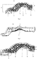
- FIG. 1 is a structural schematic view of a longitudinal beam involved in the present invention, which is a front view.
- the longitudinal beam 1 comprises a front segment 11, a middle segment 12, and a back segment 13 extending in a travelling direction (i.e., a forward and backward direction) of a vehicle.
- the middle segment 12 is located between the front segment 11 and the back segment 13.
- the middle segment 12 of the longitudinal beam is formed by the front segment 11 and the back segment 13 turning upwards in the height direction of the vehicle to form a bending structure.
- the longitudinal beam 1 is not in linear shape, but rather forms a shape of the Chinese character " ".
- FIG. 2 is a top view of the longitudinal beam in FIG. 1 .
- the longitudinal beam has a variable width in the direction of the width of the vehicle.
- the width of the middle segment of the longitudinal beam is smaller than the width of the front segment
- the width of the middle segment of the longitudinal beam is further smaller than the width of the back segment, as can be seen from the figure, the width of the middle segment w is much smaller than the front segment or the back segment, that is, the minimum width of the longitudinal beam appears on the middle segment.
- the position of the middle segment is associated with the position of the seat, primarily the second row of seats, in the vehicle.
- the width of the seat is relatively wide (such as a seat for three), the lateral space occupied by the seat is relatively large, the width of the longitudinal beam at the middle segment is set to be narrow, and in the lateral space, it may be used to make way for a certain space to meet the space requirements of the seat; also, the part of space the longitudinal beam makes way for may also be installed with an absorber 5 of the carframe, so that the absorber and the air spring with the buffering effect are arranged separately, avoiding large size arrangement space requirements caused by integrating the two together.
- the mounting position of absorber 5 has been shown in the figure. In this case, the middle segment loses the inside space, which results in a sharp narrowing of the width of the longitudinal beam at the middle segment.
- a rib structure 14 is arranged on at least one side of the longitudinal beam 1 in the width direction on the front segment 11, the middle segment 12, and the back segment 13.
- the rib structure 14 includes a plurality of ribs, and the ribs are continuously arranged to form a rib structure.
- the so-called “continuously arranged” refers to the interconnection between the ribs, i.e., the end of each rib is connected to the end of other rib(s) (which may be one rib, and may also be two ribs, three ribs or even more ribs), thereby forming a continuous rib connection structure.
- the arrangement of the rib structure 14 is along a path following the extension direction of the longitudinal beam. As the rib structure forms a complete force transferring path, the strength of the longitudinal beam is enhanced.
- the first section a and the fifth section e generally correspond to the back segment and the front segment of the longitudinal beam
- the second section b, the third section c, and the fourth section d are bending structures.
- the third section c generally corresponds to the middle segment of the longitudinal beam
- the second section b is a connection portion connecting between the back segment and the middle segment of the longitudinal beam
- the fourth section d is the connection portion connecting between the middle segment and the front segment of the connection longitudinal beam.
- the middle segment is the bending structure on the whole of the longitudinal beam and the width of the middle segment is small, the middle segment is a weak link of the longitudinal beam in mechanics.
- the rib structure of the middle segment may also be arranged, on one side (the inside), as a shape of superposition of a intersecting shape and a frame structure such as a rectangle, square or rhombus, for example, the superposition of the shape of the Chinese character " ", rectangle, square or rhombus and the shaped of "X”, or a superposition of these above described frame structures with a shape of Chinese character " “ etc., wherein the main rib being arranged in a horizontal direction.
- the rib structure 14 is arranged in a jagged shape.
- the front segment 11 of the longitudinal beam is connected to a sill beam 2, and the back segment 13 is connected to the back anticollision beam 3.
- the collision force is transferred forward from the back segment.
- the force follows the structure of the longitudinal beam during transfer.
- the weak middle segment due to the fact that the rib structure appears to be crossed or radial and there are continuous structures between the ribs, the collision force can be dispersed towards each preset direction, effectively enhancing the strength of the longitudinal beam is in mechanics.
- the front segment 11 of the longitudinal beam is connected with the sill beam 2 through high-strength bolt connection in conjunction with a structural adhesive, and the structural adhesive is disposed on the junction face of the longitudinal beam and the sill beam.
- a mounting point 4 for an air spring is left on the middle segment of the longitudinal beam, the absorber is arranged separately from the air spring, the air spring is arranged on the longitudinal beam, and the absorber 5 is arranged on the inside of the longitudinal beam (see FIG. 2 ).
- the present longitudinal beam has good strength and can meet the back collision requirement at high speed, for example, a back collision speed of 80 km/h as specified by the U.S. automobile safety technology regulation fmvss 301.
Landscapes
- Engineering & Computer Science (AREA)
- Mechanical Engineering (AREA)
- Chemical & Material Sciences (AREA)
- Combustion & Propulsion (AREA)
- Transportation (AREA)
- Body Structure For Vehicles (AREA)
Applications Claiming Priority (2)
| Application Number | Priority Date | Filing Date | Title |
|---|---|---|---|
| CN201721355376.XU CN207644466U (zh) | 2017-10-20 | 2017-10-20 | 车辆及其纵梁 |
| PCT/CN2018/110789 WO2019076334A1 (fr) | 2017-10-20 | 2018-10-18 | Véhicule et son longeron |
Publications (2)
| Publication Number | Publication Date |
|---|---|
| EP3699063A1 true EP3699063A1 (fr) | 2020-08-26 |
| EP3699063A4 EP3699063A4 (fr) | 2021-08-04 |
Family
ID=62883907
Family Applications (1)
| Application Number | Title | Priority Date | Filing Date |
|---|---|---|---|
| EP18867805.6A Withdrawn EP3699063A4 (fr) | 2017-10-20 | 2018-10-18 | Véhicule et son longeron |
Country Status (3)
| Country | Link |
|---|---|
| EP (1) | EP3699063A4 (fr) |
| CN (1) | CN207644466U (fr) |
| WO (1) | WO2019076334A1 (fr) |
Cited By (1)
| Publication number | Priority date | Publication date | Assignee | Title |
|---|---|---|---|---|
| US11358645B2 (en) | 2019-01-23 | 2022-06-14 | Toyota Jidosha Kabushiki Kaisha | Vehicle body structure member |
Families Citing this family (3)
| Publication number | Priority date | Publication date | Assignee | Title |
|---|---|---|---|---|
| CN207644466U (zh) * | 2017-10-20 | 2018-07-24 | 蔚来汽车有限公司 | 车辆及其纵梁 |
| CN111645764B (zh) * | 2019-03-04 | 2024-12-27 | 广州汽车集团股份有限公司 | 一种车辆后地板框架结构及具有其的车辆 |
| CN113104118A (zh) * | 2021-04-29 | 2021-07-13 | 黄冈格罗夫氢能汽车有限公司 | 一种氢能汽车车身连接结构 |
Family Cites Families (10)
| Publication number | Priority date | Publication date | Assignee | Title |
|---|---|---|---|---|
| US7513329B2 (en) * | 2005-03-02 | 2009-04-07 | Honda Motor Co., Ltd. | Vehicle rear body structure |
| JP4431079B2 (ja) * | 2005-05-10 | 2010-03-10 | 本田技研工業株式会社 | 自動車の車体構造 |
| JP5656032B2 (ja) * | 2010-08-03 | 2015-01-21 | 三菱自動車工業株式会社 | 車両の後部保護構造 |
| US9637172B2 (en) * | 2013-11-12 | 2017-05-02 | Nissan Motor Co., Ltd. | Vehicle body structure for automobile |
| CN105313972B (zh) * | 2014-07-31 | 2018-03-06 | 长城汽车股份有限公司 | 用于车辆的车身及具有其的车辆 |
| CN204567770U (zh) * | 2015-03-23 | 2015-08-19 | 上海通用汽车有限公司 | 一种车身的后纵梁 |
| US10131381B2 (en) * | 2015-06-30 | 2018-11-20 | Faraday & Future Inc. | Joint for an underbody of a motor vehicle |
| US9828037B2 (en) * | 2015-09-16 | 2017-11-28 | Tesla, Inc. | Structural beam member with dual side reinforcement ribbing |
| CN106891998B (zh) * | 2017-04-07 | 2019-03-26 | 上海蔚来汽车有限公司 | 后纵梁加强件、后纵梁、后防撞梁、车体结构以及车辆 |
| CN207644466U (zh) * | 2017-10-20 | 2018-07-24 | 蔚来汽车有限公司 | 车辆及其纵梁 |
-
2017
- 2017-10-20 CN CN201721355376.XU patent/CN207644466U/zh active Active
-
2018
- 2018-10-18 EP EP18867805.6A patent/EP3699063A4/fr not_active Withdrawn
- 2018-10-18 WO PCT/CN2018/110789 patent/WO2019076334A1/fr not_active Ceased
Cited By (1)
| Publication number | Priority date | Publication date | Assignee | Title |
|---|---|---|---|---|
| US11358645B2 (en) | 2019-01-23 | 2022-06-14 | Toyota Jidosha Kabushiki Kaisha | Vehicle body structure member |
Also Published As
| Publication number | Publication date |
|---|---|
| CN207644466U (zh) | 2018-07-24 |
| EP3699063A4 (fr) | 2021-08-04 |
| WO2019076334A1 (fr) | 2019-04-25 |
Similar Documents
| Publication | Publication Date | Title |
|---|---|---|
| EP3699063A1 (fr) | Véhicule et son longeron | |
| CN103770841B (zh) | 一种汽车车身骨架结构 | |
| CN107000664B (zh) | 用于吸收小偏置碰撞力的车辆前部结构 | |
| US8864198B2 (en) | Tubular back beam for vehicle | |
| CN105882762B (zh) | 散热器支撑结构 | |
| US9527464B2 (en) | Bumpers including a reinforcement bracket and vehicles incorporating the same | |
| EP2879940B1 (fr) | Structure inférieure de véhicule | |
| JP4875559B2 (ja) | 車体フレーム構造 | |
| CN104071234A (zh) | 车身构造 | |
| US8439412B2 (en) | Motor vehicle forward structure | |
| CN106458263A (zh) | 车辆撞击结构 | |
| CN211543704U (zh) | 一种纯电动车下车身结构及纯电动车 | |
| EP2990310B1 (fr) | Dispositif de commande de flux pour véhicule | |
| US8523251B1 (en) | Bumper fascia support assembly | |
| JP2016052820A (ja) | リヤシートバックフレーム構造 | |
| CN106476900B (zh) | 一种后部总成和包括该后部总成的汽车 | |
| CN107787280B (zh) | 用于机动车的变形元件和具有这样的变形元件的机动车 | |
| CN110962701B (zh) | 一种前排座椅横梁组件 | |
| US9358941B1 (en) | Bumpers including a reinforcement patch and vehicles incorporating the same | |
| US9889810B2 (en) | Utility vehicle | |
| JP6172841B2 (ja) | 車体構造 | |
| JP2008273379A (ja) | 車体構造 | |
| JP7659798B2 (ja) | 車両のフレーム構造 | |
| JP6063798B2 (ja) | 車体構造 | |
| JP2014226953A (ja) | ホイル内駆動ユニットの冷却構造 |
Legal Events
| Date | Code | Title | Description |
|---|---|---|---|
| STAA | Information on the status of an ep patent application or granted ep patent |
Free format text: STATUS: THE INTERNATIONAL PUBLICATION HAS BEEN MADE |
|
| PUAI | Public reference made under article 153(3) epc to a published international application that has entered the european phase |
Free format text: ORIGINAL CODE: 0009012 |
|
| STAA | Information on the status of an ep patent application or granted ep patent |
Free format text: STATUS: REQUEST FOR EXAMINATION WAS MADE |
|
| 17P | Request for examination filed |
Effective date: 20200519 |
|
| AK | Designated contracting states |
Kind code of ref document: A1 Designated state(s): AL AT BE BG CH CY CZ DE DK EE ES FI FR GB GR HR HU IE IS IT LI LT LU LV MC MK MT NL NO PL PT RO RS SE SI SK SM TR |
|
| AX | Request for extension of the european patent |
Extension state: BA ME |
|
| RAP1 | Party data changed (applicant data changed or rights of an application transferred) |
Owner name: NIO (ANHUI) HOLDING CO., LTD. |
|
| RIN1 | Information on inventor provided before grant (corrected) |
Inventor name: LIU, JIAN |
|
| DAV | Request for validation of the european patent (deleted) | ||
| DAX | Request for extension of the european patent (deleted) | ||
| A4 | Supplementary search report drawn up and despatched |
Effective date: 20210705 |
|
| RIC1 | Information provided on ipc code assigned before grant |
Ipc: B62D 21/15 20060101AFI20210629BHEP Ipc: B60G 15/00 20060101ALI20210629BHEP Ipc: B62D 25/08 20060101ALI20210629BHEP Ipc: B62D 25/02 20060101ALI20210629BHEP Ipc: B62D 29/00 20060101ALI20210629BHEP Ipc: B62D 27/02 20060101ALI20210629BHEP |
|
| STAA | Information on the status of an ep patent application or granted ep patent |
Free format text: STATUS: THE APPLICATION HAS BEEN WITHDRAWN |
|
| 18W | Application withdrawn |
Effective date: 20220202 |