EP3699111B1 - Paquet composite destiné à être rempli d'une matière liquide - Google Patents
Paquet composite destiné à être rempli d'une matière liquide Download PDFInfo
- Publication number
- EP3699111B1 EP3699111B1 EP18867478.2A EP18867478A EP3699111B1 EP 3699111 B1 EP3699111 B1 EP 3699111B1 EP 18867478 A EP18867478 A EP 18867478A EP 3699111 B1 EP3699111 B1 EP 3699111B1
- Authority
- EP
- European Patent Office
- Prior art keywords
- liquid material
- filling
- composite pack
- exterior member
- standing
- Prior art date
- Legal status (The legal status is an assumption and is not a legal conclusion. Google has not performed a legal analysis and makes no representation as to the accuracy of the status listed.)
- Active
Links
Images








Classifications
-
- B—PERFORMING OPERATIONS; TRANSPORTING
- B65—CONVEYING; PACKING; STORING; HANDLING THIN OR FILAMENTARY MATERIAL
- B65D—CONTAINERS FOR STORAGE OR TRANSPORT OF ARTICLES OR MATERIALS, e.g. BAGS, BARRELS, BOTTLES, BOXES, CANS, CARTONS, CRATES, DRUMS, JARS, TANKS, HOPPERS, FORWARDING CONTAINERS; ACCESSORIES, CLOSURES, OR FITTINGS THEREFOR; PACKAGING ELEMENTS; PACKAGES
- B65D5/00—Rigid or semi-rigid containers of polygonal cross-section, e.g. boxes, cartons or trays, formed by folding or erecting one or more blanks made of paper
- B65D5/42—Details of containers or of foldable or erectable container blanks
- B65D5/54—Lines of weakness to facilitate opening of container or dividing it into separate parts by cutting or tearing
-
- B—PERFORMING OPERATIONS; TRANSPORTING
- B65—CONVEYING; PACKING; STORING; HANDLING THIN OR FILAMENTARY MATERIAL
- B65D—CONTAINERS FOR STORAGE OR TRANSPORT OF ARTICLES OR MATERIALS, e.g. BAGS, BARRELS, BOTTLES, BOXES, CANS, CARTONS, CRATES, DRUMS, JARS, TANKS, HOPPERS, FORWARDING CONTAINERS; ACCESSORIES, CLOSURES, OR FITTINGS THEREFOR; PACKAGING ELEMENTS; PACKAGES
- B65D77/00—Packages formed by enclosing articles or materials in preformed containers, e.g. boxes, cartons, sacks or bags
- B65D77/04—Articles or materials enclosed in two or more containers disposed one within another
- B65D77/06—Liquids or semi-liquids or other materials or articles enclosed in flexible containers disposed within rigid containers
- B65D77/062—Flexible containers disposed within polygonal containers formed by folding a carton blank
- B65D77/064—Flexible containers disposed within polygonal containers formed by folding a carton blank comprising discharging means formed by cutting a part, e.g. a corner, of the flexible container
-
- B—PERFORMING OPERATIONS; TRANSPORTING
- B65—CONVEYING; PACKING; STORING; HANDLING THIN OR FILAMENTARY MATERIAL
- B65D—CONTAINERS FOR STORAGE OR TRANSPORT OF ARTICLES OR MATERIALS, e.g. BAGS, BARRELS, BOTTLES, BOXES, CANS, CARTONS, CRATES, DRUMS, JARS, TANKS, HOPPERS, FORWARDING CONTAINERS; ACCESSORIES, CLOSURES, OR FITTINGS THEREFOR; PACKAGING ELEMENTS; PACKAGES
- B65D21/00—Nestable, stackable or joinable containers; Containers of variable capacity
- B65D21/02—Containers specially shaped, or provided with fittings or attachments, to facilitate nesting, stacking, or joining together
-
- B—PERFORMING OPERATIONS; TRANSPORTING
- B65—CONVEYING; PACKING; STORING; HANDLING THIN OR FILAMENTARY MATERIAL
- B65D—CONTAINERS FOR STORAGE OR TRANSPORT OF ARTICLES OR MATERIALS, e.g. BAGS, BARRELS, BOTTLES, BOXES, CANS, CARTONS, CRATES, DRUMS, JARS, TANKS, HOPPERS, FORWARDING CONTAINERS; ACCESSORIES, CLOSURES, OR FITTINGS THEREFOR; PACKAGING ELEMENTS; PACKAGES
- B65D5/00—Rigid or semi-rigid containers of polygonal cross-section, e.g. boxes, cartons or trays, formed by folding or erecting one or more blanks made of paper
- B65D5/02—Rigid or semi-rigid containers of polygonal cross-section, e.g. boxes, cartons or trays, formed by folding or erecting one or more blanks made of paper by folding or erecting a single blank to form a tubular body with or without subsequent folding operations, or the addition of separate elements, to close the ends of the body
- B65D5/06—Rigid or semi-rigid containers of polygonal cross-section, e.g. boxes, cartons or trays, formed by folding or erecting one or more blanks made of paper by folding or erecting a single blank to form a tubular body with or without subsequent folding operations, or the addition of separate elements, to close the ends of the body with end-closing or contents-supporting elements formed by folding inwardly a wall extending from, and continuously around, an end of the tubular body
- B65D5/067—Gable-top containers
- B65D5/068—Gable-top containers with supplemental means facilitating the opening, e.g. tear lines, tear tabs
-
- B—PERFORMING OPERATIONS; TRANSPORTING
- B65—CONVEYING; PACKING; STORING; HANDLING THIN OR FILAMENTARY MATERIAL
- B65D—CONTAINERS FOR STORAGE OR TRANSPORT OF ARTICLES OR MATERIALS, e.g. BAGS, BARRELS, BOTTLES, BOXES, CANS, CARTONS, CRATES, DRUMS, JARS, TANKS, HOPPERS, FORWARDING CONTAINERS; ACCESSORIES, CLOSURES, OR FITTINGS THEREFOR; PACKAGING ELEMENTS; PACKAGES
- B65D5/00—Rigid or semi-rigid containers of polygonal cross-section, e.g. boxes, cartons or trays, formed by folding or erecting one or more blanks made of paper
- B65D5/42—Details of containers or of foldable or erectable container blanks
- B65D5/70—Break-in flaps, or members adapted to be torn-off, to provide pouring openings
-
- B—PERFORMING OPERATIONS; TRANSPORTING
- B65—CONVEYING; PACKING; STORING; HANDLING THIN OR FILAMENTARY MATERIAL
- B65D—CONTAINERS FOR STORAGE OR TRANSPORT OF ARTICLES OR MATERIALS, e.g. BAGS, BARRELS, BOTTLES, BOXES, CANS, CARTONS, CRATES, DRUMS, JARS, TANKS, HOPPERS, FORWARDING CONTAINERS; ACCESSORIES, CLOSURES, OR FITTINGS THEREFOR; PACKAGING ELEMENTS; PACKAGES
- B65D5/00—Rigid or semi-rigid containers of polygonal cross-section, e.g. boxes, cartons or trays, formed by folding or erecting one or more blanks made of paper
- B65D5/42—Details of containers or of foldable or erectable container blanks
- B65D5/72—Contents-dispensing means
- B65D5/74—Spouts
- B65D5/741—Spouts for containers having a tubular body
- B65D5/742—Spouts formed by deforming or tearing the closure flaps or severed or incised parts of the closure flaps
-
- B—PERFORMING OPERATIONS; TRANSPORTING
- B65—CONVEYING; PACKING; STORING; HANDLING THIN OR FILAMENTARY MATERIAL
- B65D—CONTAINERS FOR STORAGE OR TRANSPORT OF ARTICLES OR MATERIALS, e.g. BAGS, BARRELS, BOTTLES, BOXES, CANS, CARTONS, CRATES, DRUMS, JARS, TANKS, HOPPERS, FORWARDING CONTAINERS; ACCESSORIES, CLOSURES, OR FITTINGS THEREFOR; PACKAGING ELEMENTS; PACKAGES
- B65D77/00—Packages formed by enclosing articles or materials in preformed containers, e.g. boxes, cartons, sacks or bags
- B65D77/04—Articles or materials enclosed in two or more containers disposed one within another
- B65D77/06—Liquids or semi-liquids or other materials or articles enclosed in flexible containers disposed within rigid containers
Definitions
- This invention relates to a composite pack for filling a liquid material, which is comprised of an interior member formed by filling and packing a liquid or viscous material into a package bag made of a plastic film or the like and an exterior member made of a paper or the like and housing and holding the interior member therein, and particularly proposes a composite pack for filling a liquid material capable of stably holding a non-self-supportable interior member for filling a liquid material such as drinks, medicines, chemicals or the like (assisting self-support of the interior member) and attaining an increase of a volumetric efficiency for the liquid material and an effective utilization of a display space in the displaying or the like.
- the package bag used in the liquid material filling package member is made from a soft laminate plastic film. Since the liquid material filling package member itself has not a self-supportability or a definite shape-ability, it is housed into an exterior member made of a self-supporting package bag or vessel or an exterior vessel in the transportation, storage, use or the like thereof.
- Patent Documents 3 and 4 are known as a liquid material filling paper vessel different from the aforementioned composite pack and using a gable top paper pack (milk carton or the like) for housing a milk or the like.
- Patent Document 5 discloses a composite pack for filling a liquid material, which is comprised of a bag-shaped interior member formed by filling a liquid material into a soft package bag and an exterior member having a cylindrical body provided on its lower end with a bottom wall and on its upper end with an opening portion for housing the interior member the exterior member having a sealing structure unit comprising a top face wall for closing the opening portion and plural vertical ribs standing up from the top face wall Futher state of art is described in patent documents 6 to 8.
- All of the self-supporting exterior vessels (package bags or vessels) used in the above prior arts are constructed so that a lower portion is cylindrical of polygon or the like as a planar view and a body portion is cylindrical of circular as a planar view and a top portion is plate-like in correspondence to a stereoscopic form in the standing posture of the liquid material filling package member to be housed.
- the volume of housing the liquid material in the top portion becomes small, so that there is a problem that the volume efficiency of the liquid material (volume of liquid material/height of exterior vessel) is low as compared to a paper carton or a plastic bottle.
- the gable top paper pack as disclosed in Patent Documents 3 and 4 is recently required to be sealed completely by increasing a sealing strength of an overlapped portion in a top end in order to prevent not only liquid leakage at a distribution level but also incorporation of foreign matter or the like. Therefore, there are problems that children or old men being weak in the power cannot open the pack by its hand force and also if it is intended to open the pack forcibly, an unintended portion is broken or a pouring port is deformed.
- an object of the invention to provide a composite pack for filling a liquid material, which is comprised of an interior member as a non-self-supporting liquid material filling package member for filling liquid material and an exterior member capable of stably holding the interior member and is capable of attaining not only an increase of a volume efficiency for the liquid material but also space saving in the display or the like.
- the inventor has developed a liquid material filling composite pack having the following summary and constructions as a vessel capable of overcoming the aforementioned issues inherent to the prior arts.
- the invention is a composite pack for filling a liquid material, which is comprised of a bag-shaped interior member formed by filling a liquid material into a soft package bag and an exterior member having a cylindrical body provided on its lower end with a bottom wall and on its upper end with an opening portion for housing the interior member, characterized in that the interior member is provided with a sheet-like pouring nozzle for liquid material protruding to an upper end portion or a side end upper portion of the package bag, and the exterior member has a sealing structure unit comprising a top face wall for closing the opening portion and plural vertical ribs standing up from the top face wall.
- the opening portion located at the upper end of the cylindrical body of the exterior member is sealed by the sealing structure unit comprised of plural vertical ribs and top face wall (top face plate), so that the cylindrical body of the exterior member housing the interior member may be a box-type columnar body or a cylindrical body having an approximately equal opening area and hence a zone from the bottom portion to the upper portion of the cylindrical body can be contributed to the housing of the liquid material.
- the volume efficiency for the liquid material is increased to the same level as in the plastic bottle and the fitting performance is good in the display or the like of arranging plural packs and space saving can be attained.
- one of the plural vertical ribs constituting the sealing structure unit arranged in the opening portion at the upper end of the cylindrical body of the exterior member is the vertical cover rib for pinching and storing the sheet-like pouring nozzle for the liquid material (hereinafter referred to as "sheet-like nozzle") protruded from the upper end portion or side end upper portion of the interior member. Therefore, even when the sheet-like nozzle is made from a thin and soft plastic film, it is protected with the vertical cover rib, so that there is no fear of deforming or erroneously opening in the handling for transportation or the like, and the sheet-like nozzle can be exposed outward in use by cutting out only the vertical cover rib along the given separable line.
- each of the plural vertical ribs constituting the sealing structure unit is formed by overlapping the pair of the standing walls formed by cutting and raising a part of the top face wall (communicating to the top face wall), whereby the opening portion at the upper end of the cylindrical body of the exterior member can be sealed while suppressing the height of the exterior member.
- the opening portion at the upper end of the cylindrical body can be opened simply by pulling the plural vertical ribs constituting the sealing structure unit in a direction of separating from each other with fingers, respectively, so that disposal can be performed by taking out the interior member from the exterior member and conducting separation by every material.
- the plural vertical ribs (preferably not less than 3 ribs) is arranged in the sealing structure unit, whereby the plurality of the composite packs for filling liquid material can be laminated through these vertical ribs and space saving can be attained in the transportation, display and so on.
- the vertical ribs in the sealing structure unit are arranged radially from an approximately central position of the exterior member as a planar view of the exterior member, preferably extended in a cruciform direction. Therefore, these vertical ribs can be distorted independently and softly, so that even if the composite pack for filling liquid material is fallen down accidentally, the falling shock is absorbed by each of the vertical ribs and hence the joint portion of the vertical rib cannot be peeled off simply but also the composite pack for filling liquid material (exterior member) can be held at its original form.
- the sheet-like nozzle when the interior member is joined and fixed to the exterior member at least at an upper end portion backward a top thereof (opposite side to the protruding position of the nozzle), the sheet-like nozzle is tilted downward for pouring the liquid material from the composite pack for filling liquid material, whereby it is made possible to suppress the deformation of the sheet-like nozzle and conduct smooth pouring. Even if the sheet-like nozzle has a self-sealing function, penetration of external air can be prevented sufficiently without blocking adhesion of faces in the pouring pathway.
- the package bag used for constituting the interior member is preferable to be made from the single plastic film or a laminate film formed by laminating two or more plastic films or plural plastic films inclusive of a metallic foil.
- the occurrence of wrinkles in the interior member can be suppressed in the tilting of the composite pack for filling liquid material for pouring the liquid material and the slippage of the interior member can be suppressed.
- the gradient of the faces of the top face wall located at both sides sandwiching the vertical cover rib are made larger than the gradient of the other faces of the top face wall, whereby a space forming the vertical cover rib can be made large and the protruding end of the sheet-like nozzle housed in the side edge of the vertical cover rib and inside thereof can be positioned inward the side wall of the cylindrical body of the exterior member. Therefore, when the plural composite packs for filling liquid material are displayed and housed, space saving can be attained without knocking these composite packs for filling liquid material to each other, while breakage or the like can be reduced.
- the sheet-like nozzle when the vertical cover rib is cut out, the sheet-like nozzle can be protruded from the adjoining top face wall over a full length of the nozzle from the base end portion thereof. Therefore, the sheet-like nozzle is not influenced by clamping of the remaining vertical cover rib or the like and the packed material can be poured from the tip of the sheet-like nozzle into a target direction while controlling the pouring amount to improve liquid-cut property.
- the above effect can be developed more effectively by elongating the standing base end side of the vertical cover rib downward and positioning to a level lower than the standing base end side of the other vertical rib.
- the exterior member is provided with the detachable cap capable of covering the sheet-like nozzle exposed from the sealing structure unit to outside, whereby contamination of the pouring port can be prevented even if the sheet-like nozzle is stored after the opening, which is hygienic. Also, when the cap is provided with a clamping structure for the sheet-like nozzle, even if the composite pack for filling liquid material is fallen down accidentally after the opening of the sheet-like nozzle, leakage of the liquid material can be prevented.
- the composite pack for filling liquid material is constructed with a bag-shaped interior member formed by filling a liquid material into a soft package bag made from a plastic film or the like and an exterior member made from a paper, a plastic or the like for housing and holding the interior member.
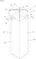
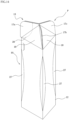
- FIG. 1 is a perspective view illustrating an embodiment of a composite pack P for filling liquid material
- FIG. 2 is a perspective view illustrating an upper portion at a rear side of the composite pack P for filling liquid material
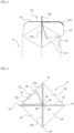
- FIG. 3 is a plan view of the composite pack P for filling liquid material
- FIG. 4 is a bottom view of the composite pack P for filling liquid material.
- the composite pack P for filling liquid material is constructed with an interior member 30 shown by a dotted line in FIG. 1 and an exterior member 10 for housing and holding the interior member 30.
- the interior member 30 and the exterior member 10 are preferable to be fixed to each other by joining in at least one location.
- a fixed portion 28 is preferable an upper end portion rearward a top of the interior member 30 (a side opposite to a protruding position of a sheet-like nozzle 31) as shown in FIG. 1 .
- the fixed portion 28 By the arrangement of the fixed portion 28 is made possible to perform smooth pouring without causing deformation of the sheet-like nozzle 31 when the composite pack P for filling liquid material is tilted so as to direct the sheet-like nozzle 31 downward for pouring the liquid material, while penetration of ambient air can be prevented sufficiently without blocking adhesion of inner faces in a pouring pathway to each other even if the sheet-like nozzle 31 has a self-sealing function of preventing penetration of ambient air as mentioned later.
- the fixed portion 28 may be disposed in a position just beneath the sheet-like nozzle 31 in the interior member 30 as shown in FIG. 1 .
- it may be formed by cutting a part of the exterior member 10 and pushing inward and sticking an inner face of the cut portion to an outer face of the interior member 30 located at the inside thereof as shown in the figure.
- the upper portion of the composite pack P for filling liquid material is sealed by a sealing structure unit 13 comprised of four vertical ribs 17a-17d made from a pair of standing walls arranged radially (cruciform) and a top face wall 18 as shown in a plan view of FIG. 3 .
- the lower portion of the composite pack P for filling liquid material is provided with a bottom wall 25 (bottom plate) as shown in a bottom view of FIG. 4 , and the bottom wall 25 is formed by engaging or sticking plural bottom walls (4 walls in FIG. 4 ) continuing from a lower end of a cylindrical body 12 to each other.
- the composite pack P for filling liquid material is comprised of the interior member 30 formed by filling the liquid material into the package bag and the exterior member 10 and the liquid material is not directly filled into the exterior member 10, so that the bottom wall 25 of the exterior member 10 may be anything as far as self-standing property is applied and falling-off of the interior member 30 can be prevented.
- the exterior member 10 is provided with a cylindrical body 12 and a sealing structure unit 13 for sealing an opening portion 12' located at the upper end of the cylindrical body 12 (12' is set as "upper end opened portion” hereinafter).
- the sealing structure unit 13 is constructed with four vertical ribs 17a-17d composed of the pair of standing walls arranged radially and a mountain type top face wall 18 (top face plate) connecting the vertical ribs 17a-17d to the upper end opened portion 12'.
- the cylindrical body 12 of the exterior member 10 is shown to be a quadrangular prism body as an example, but is not limited thereto in the invention.
- the cylindrical body 12 may be a polygonal prism such as triangular prism, pentagonal prism or the like or a circular cylinder.
- the top face wall 18 may be a flat form approximately perpendicular to the vertical ribs 17a-17d as shown in FIG. 5 . In the latter case, the height of the exterior member 10 can be suppressed.
- the material of the exterior member 10 is not particularly limited, but is preferable to be a material having a strength capable of applying the self-standing property as the composite pack P for filling liquid material. It may be a paper, a plastic film, a composite of paper and plastic film or the like.
- the composite of paper and plastic film is ones obtained by using a paper as a base and laminating at least one plastic film such as nylon, polyester, polyethylene or the like thereon. It is further preferable to laminate a metallic foil, a metal deposited layer, various barrier layers or the like, if necessary.
- the exterior member 10 is preferable to be formed by folding the one sheet in view of increasing the production efficiency. In this embodiment, the exterior member 10 is described to be made from a paper as an example.
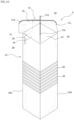
- FIG. 6 is a perspective view illustrating an embodiment of the exterior member 10 before the housing of the interior member 30.
- a circular body 11 forming the sealing structure unit 13 for sealing the upper end opened portion 12' is provided on an upper end edge of the cylindrical body 12.
- the interior member 30 filled with the liquid material is housed through the upper end opened portion 12' of the cylindrical body 12.
- the circular body 11 is comprised of a pair of standing walls by folding mountain-folded lines 14 extending from 4 corner portions of the cylindrical body 12 along valley-folded lines 15 formed between the mountain-folded lines 14 and butting four internal tip portions 16 in the valley-folded lines 15 to each other to thereby form the sealing structure unit 13 comprised of four radially positioned (cruciform) vertical ribs 17a-17d (mountain-folded portions) and the mountain-shaped top face wall 18 formed between the vertical ribs 17a-17d and the upper end opened portion 12'.
- four vertical ribs 17a-17d are disposed in the sealing structure unit 13. It is preferable to disposed three or more vertical ribs in the sealing structure unit 13. The number of the ribs is properly set in accordance with the purpose, applications and so on.
- the liquid material can be filled at the same opening area over a full length from the bottom portion to the upper portion of the cylindrical body 12 of the exterior member 10, while the height of the composite pack P for filling liquid material can be decreased as far as possible by sealing the upper end opened portion 12' of the cylindrical body 12 with the sealing structure unit 13 disposed in the upper end opened portion 12'.
- the volume efficiency of the liquid material is 2 times or more of an exterior vessel shown in the prior art and can be increased to the same level in the usually distributed plastic bottles.
- each vertical rib 17a-17d in the sealing structure unit 13 are formed by butting four internal tip portions 16 in the valley-folded lines 15 to each other as mentioned above, so that the upper end opened portion 12' can be opened easily by pulling two opposed vertical ribs, i.e. vertical rib 17a and vertical rib 17c or vertical rib 17b and vertical rib 17d in FIG. 1 in a direction of separating away from each other with fingers.
- the interior member 30 is taken out from the exterior member 10, whereby both the materials can be sorted and disposed, respectively.
- the sheet-like nozzle 31 of the interior member 30 is housed between the pair of standing walls in one of the four vertical ribs 17a-17d, i.e. the vertical rib 17a in FIG. 1 as indicated by dotted lines, so that the vertical rib 17a acts as a cover 19 for the sheet-like nozzle 31.
- the sheet-like nozzle 31 is protected from both front and rear faces by the cover 19 before the start of use, and hence there is no fear of deforming or erroneously opening the sheet-like nozzle 31 in the handling for transportation or the like. If at least a part of the sheet-like nozzle 31 is detachably stuck or fused to an inner face of the cover 19, the deformation or the like of the sheet-like nozzle 31 can be more suppressed.
- the remaining three vertical ribs 17b-17d act as sealing pieces by sticking or fusing the pairs of standing walls overlapped at least in their upper end portions for sealing the upper end opened portion 12' of the cylindrical body 12 in cooperation with the top face wall 18.
- each of the four vertical ribs 17a-17d is disposed on a straight line passing through four corners thereof in a plan view of the cylindrical body 12. It is preferable that the vertical rib 17a as the cover 19 for housing and holding the sheet-like nozzle 31 is positioned at least on a straight line passing through at least one corner portion of the cylindrical body 12.
- the cover 19 can be cut out along a predetermined cut-off line20 of perforation or the like formed in the sealing structure unit 13. By cutting out the cover 19 can be exposed the sheet-like nozzle 31 from inside to outside.
- one of the pair of standing walls constituting the vertical rib 17a is a flap 21 as shown in FIGS. 2 and 3 .
- the flap 21 can be opened by using the mountain-folded line 14 as shown in FIG. 8 or an upper end edge of the vertical rib 17a as shown in FIG. 9 as a starting point.
- the flap 21 is opened with fingers by using the mountain-folded line 14 as a starting point and then the vertical rib 17a (cover portion 19) is cut out along the predetermined cut-off line 20 formed in the other wall to expose the sheet-like nozzle 31 outward. Moreover, it is preferable that at least a part of the flap 21 is stuck or fused to the other standing wall of the vertical rib 17a to suppress exposure of the sheet-like nozzle 31 from inside to outside until the start of use.
- a predetermined crushing line 24a is formed in the cylindrical body 12 of the exterior member 10 located just beneath the sheet-like nozzle 31 (corner portion of quadrangular prism in FIG. 1 ) and a predetermined another crushing line 24b is formed in the cylindrical body 12 located opposite thereto (another corner portion of the quadrangular prism in FIG. 1 ).
- the bottom wall 25 is provided with a predetermined bending line 26 of perforation or the like communicated with the predetermined crushing lines 24a and 24b for bending the bottom wall 25 inward the cylindrical body 20 as shown in Fig.4 .
- the exterior member 10 can be crushed along the predetermined crushing lines 24a, 24b and the predetermined bending line 26 until the cylindrical body 12 becomes flat, so that the pouring amount of the liquid material can be adjusted by the pushing amount with fingers, while the liquid material can be squeezed out up to the end even if the residual amount of the liquid material becomes small.
- the cylindrical body 12 of the exterior member 10 is a quadrangular prism, so that the predetermined crushing line 24b is located in a corner portion of the cylindrical body 12. However, the predetermined crushing line 24b is properly formed in the wall portion of the cylindrical body 12 in accordance with the form of the cylindrical body 12.
- FIG. 10 is a perspective view illustrating another embodiment of the composite pack P for filling liquid material according to the invention.
- this composite pack P for filling liquid material plural concave strips 29 each extending in a horizontal direction are formed in the wall face of the cylindrical body 12 of the exterior member 10 at a position gripping with fingers, for example, within a range of about 5 cm upward and downward from a central position in the height direction of the cylindrical body 12. The slipping off of the composite pack can be suppressed by these concave strips 29 when it is gripped with fingers.
- the concave strips 29 can be formed by pressing a material constituting the exterior member 10 such as paper or the like in a given form.
- FIG. 11 is a perspective view illustrating the other embodiment of the composite pack P for filling liquid material according to the invention, which is different from the composite pack P for filling liquid material of FIG. 1 in the structure of the pair of standing walls constituting the vertical rib 17a of the exterior member 10.
- the standing walls have the same form and the predetermined cut-off line 20 is formed in each of the two standing walls in the same form. Therefore, the vertical rib 17a composed of the pair of standing walls (cover 19) can be cut out at once by tearing or folding along the predetermined cut-off lines 20.
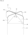
- FIG. 12 is a perspective view illustrating another embodiment of the sealing structure unit 13 in the composite pack P for filling liquid material according to the invention. As shown in FIG. 12 , the vertical ribs 17a-17d are segmented through an incision 37 formed in a central portion thereof, respectively.
- the four vertical ribs 17a-17d are held at an independent state, respectively, so that even if the composite pack P for filling liquid material is dropped in error during the handling or the like, the dropping impact is absorbed by softly distorting each of the vertical ribs 17a-17d and the joint of the vertical ribs 17a-17d (between mutual walls) is prevented from peeling, deforming or the like and hence the composite pack P for filling liquid material (exterior member 10) can be held at its original form.
- the sealing structure unit 13 can be opened easily by using the incision 37 as a starting point. Furthermore, the four vertical ribs 17a-17d are at an independent state, respectively, so that inner faces of the two standing walls are easily overlapped to each other, and hence the sealing structure unit 13 can be shaped easily.
- At least one connecting piece 22 connecting one standing wall to the other standing wall is disposed in each upper end portion of the vertical ribs 17a-17d.
- the joining strength between the pair of standing walls in each of the vertical ribs 17a-17d is increased by the connecting piece 22, so that even if the composite pack P for filling liquid material is dropped in error during the handling or the like, the joint of the vertical ribs 17a-17d (between mutual standing walls in the pair) is prevented from peeling, deforming or the like and hence the composite pack P for filling liquid material (exterior member 10) can be held at its original form.
- the connecting piece 22 is made of a member different from the exterior member 10. As shown in FIG. 13 , the connecting piece 22 for connecting the two standing walls can be formed by arranging a protrusion piece 22a continued from one wall in the pair of standing wall constituting the vertical rib 17c and folding or sticking the protrusion piece 22a to the wall face of the other wall.
- the connecting piece 22 is strongly stuck to the wall faces of the vertical ribs 17a and 17b, when the interior member 30 is taken out from the exterior member 10, for example, in the disposal or the like of the composite pack P for filling liquid material, the connecting piece 22 cannot be broken by a force with fingers and hence there is a fear that the sealing structure unit 13 cannot be opened easily. As shown enlargedly in FIG. 13(a) , therefore, it is preferable to dispose a notch portion 23 in the connecting piece 22 between double standing walls constituting the vertical rib 17c, preferably in an end portion side an internal tip portion 16 of the valley-folded line 15.
- FIG. 14 is shown another embodiment of the composite pack P for filling liquid material according to the invention.
- this composite pack P for filling liquid material three vertical ribs 17a-17c are disposed as the sealing structure unit 13 of the exterior member 10.
- an easily-deforming portion 27 capable of depressing and deforming inward is disposed in a corner portion of the cylindrical body 12 of the exterior member 10 or a wall portion of the cylindrical body positioning a finger (not shown) when the cylindrical body 12 is grasped with fingers.
- the exterior member 10 is easy to grasp with fingers and the slippage of the exterior member 10 from fingers can be suppressed in the handling thereof.
- FIG. 15 a still further embodiment of the composite pack P for filling liquid material according to the invention.
- the exterior member 10 constituting this composite pack P for filling liquid material is provided with the cylindrical body 12 and the sealing structure unit 13 for sealing the upper end opened portion 12' of the cylindrical body 12.
- the sealing structure unit 13 is constructed with mountain-shaped top face walls 18a-18d and four vertical ribs 17a-17d of pairs of standing walls stood radially from the top face walls 18a-18d.
- the vertical rib 17a among these ribs acts as a cover 19 for a sheet-like nozzle 31 storing the sheet-like nozzle 31 inside in the housing of the interior member 30.
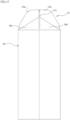
- FIG. 16 is a side view of the composite pack P for filling liquid material of FIG. 15 (side view at a side of vertical rib 17a) viewing from a direction of arrow A-A
- FIG. 17 is a side view of the composite pack P for filling liquid material viewing from a side opposite to FIG. 16 (at a side of vertical rib 17c).
- the form of the sealing structure unit 13 in the exterior member 10 is largely different between the side of vertical rib 17a and the side of vertical rib 17c.
- a standing base end side 50 of the vertical rib 17a from the top face walls 18a, 18b is extended downward and positioned to a level lower than a standing base end side 51 of the other vertical ribs 17b-17d, whereby the gradients of the top face walls 18a and 18b are made large.
- a length of the standing base end side 50 of the vertical rib 17a is 1.2-2.0 times of a length of the standing base end side 51 of the other vertical ribs 17b-17d, preferably 1.4-1.8 times thereof.
- the gradients of the top face walls 18a, 18b are made larger without decreasing the housing volume of the exterior member 10 to increase the forming space of the vertical rib 17a, whereby the whole of the sheet-like nozzle 31 can be housed in the vertical rib 17a.
- the packing liquid material is poured by cutting out the vertical rib 17a to expose the sheet-like nozzle 31 to external, the fixing and clamping of the sheet-like nozzle 31 with the remaining vertical rib 17a is made adequate, whereby the pouring amount of the packed liquid material can be controlled easily, and the pouring directionality is excellent and an effect of suppressing occurrence of liquid dripping or the like can be expected.
- FIG. 18 is shown another embodiment of the composite pack P for filling liquid material according to the invention.
- the exterior member 10 is made from a laminate plastic film of two or more layers composed of, for example, a base film layer and a sealant layer, and the cylindrical body 12 of a cylinder form is provided on its upper end portion with the sealing structure unit 13 constructed with four vertical ribs 17a-17d and mountain-shaped top face wall defined by these vertical ribs 17a-17d.
- the exterior member 10 is provided on its lower end portion with a bottom wall 25 of an ellipsoid form viewing as a plan and is self-standing by the bottom wall 25.
- the base film layer is made from polyethylene terephthalate film, nylon resin film, polypropylene or polyethylene, while the sealant layer is made from polyethylene, polypropylene or the like.
- the thickness of the laminate plastic film is 80-300 ⁇ m, preferably 100-200 ⁇ m, and further a nerve of the laminate plastic film is preferably about 40-300 mN.
- a gas burrier layer such as a SiO 2 deposited layer, an EVOH layer, a vinylidene chloride coating layer, an aluminum oxide coating layer, an Al deposited layer or a sputtering layer thereof at a thickness of 0.5-20 ⁇ m.
- a steam impermeability, a gas burrier property and so on are applied to the exterior member 10, whereby it is made possible to store the liquid material housed in the interior member 30 fresh over a long period of time.
- the exterior member 10 and the interior member 30 are made from a plastic film, respectively, so that the packed liquid material can be squeezed out by folding the composite pack P for filling liquid material when the amount of the liquid material filled in the interior member 30 is decreased.
- FIG. 19 is a perspective view illustrating an embodiment of the exterior member 10' before the housing of the interior member 30, which is comprised of a cylindrical body 12 having a cylinder form and a self-standing bottom wall 25 disposed in a bottom thereof.
- the exterior member 10' can be manufactured by various methods well-known as a method of manufacturing a standing pouch.
- the bottom wall 25 composed of a gusset bottom can be formed by sandwiching a two-folded plastic film for bottom wall between lower ends of front and rear plastic films constituting the cylindrical body 12 so as to turn up the folded portion and sealing a peripheral portion thereof at such a state.
- the cylindrical body 12 is formed by fusion-joining both side edges of the front and rear plastic films (sealing portions 12a, 12b). Also, the cylindrical body 12 may be formed by folding the single plastic film in the widthwise direction thereof.
- the upper end portion of the cylindrical body 12 is folded between the sealing portion 12a and the sealing portion 12b outward so as to pick a widthwise central portion thereof as shown in FIG. 20 .
- four internal tip portions 16 as a valley-folded portion are butted to each other to form a pair of standing walls as shown in FIG. 18 , whereby a tapered sealing structure unit 13 of four vertical ribs 17a-17d arranged radially (cruciform) can be formed.
- a cap 38 made from a resin, for example, a paper or the like may be disposed detachably on a head portion of the exterior member 10 in the composite pack P for filling liquid material as shown in FIG. 21 .
- the cap 38 is preferable to be formed in approximately same form as in the sealing structure unit 13 of the exterior member 10 shown in FIG. 1 (form somewhat larger than that of the sealing structure unit 13) so as to arrange ribs 38a-38d radially (cruciform). Any form may be taken as far as at least the sheet-like nozzle 31 can be covered.
- the cap 38 is preferable to have a clamping structure that the rib 38a covering the vertical rib 17a at least clamping the sheet-like nozzle 31 can tuck at least a part of the sheet-like nozzle 31 from both side faces thereof.
- a clamping structure is suppressed a force acting to a direction of expanding the pouring pathway of the sheet-like nozzle 31 (opening direction), whereby the leakage of the liquid material can be prevented even if the composite pack P for filling liquid material is fallen down accidentally after the opening of the sheet-like nozzle 31.
- clamping structure may be taken any structures as far as the sheet-like nozzle 31 can be clamped from both side faces thereof.
- clamping portions 40a, 40b contacting to each other are arranged in inner faces of a pair of wall portions 39a, 39b constituting the rib 38a ( FIG. 22(a) ), or one or more irregularities are disposed so as to engage with inner faces of the pair of wall portions 39a, 39b ( FIG. 22(b) ), or a dogleg-shaped folding portion 42 is disposed in a longitudinal direction of the pair of wall portions 39a, 39b as shown in FIG. 23 .
- a window hole 41 is formed in the vertical rib 17a and the clamping portions 40, 41 of the cap 38 are fitted into the window hole 41.
- the state of the cap 38 fitted into the head portion of the exterior member 10 is improved, while the detaching of the cap 38 can be prevented.
- the window hole 41 can also be observed the sheet-like nozzle 31 located at the inside of the vertical rib 17a visually.
- the cap 38 is preferable to have an engaging structure for preventing the detaching from the head portion of the exterior member 10.
- a concave portion is formed in the lower end portion of the cap 38, while a convex portion is formed in the side face of the exterior member 10, and the cap and exterior member are rigidly fixed to each other by engaging them through the concave portion and the convex portion.
- the interior member 30 can be used by filling and packing a liquid or viscous material into a package bag 32 made from a laminate film, which is formed from the single plastic film or by laminating two or more plastic films or plural plastic films including a metallic foil, for example, through liquid-in seal filling.
- a package bag 32 is made from the plastic film having sufficient thickness and nerve, the occurrence of wrinkles in the package bag 32 can be suppressed to conduct smooth pouring, while the downward slippage of the interior member 30 can be suppressed when the composite pack P for filling liquid material is tilted for pouring the liquid material.
- the sheet-like nozzle 31 is provided in a side and upper portion of the interior member 30 in a protruding condition.
- the sheet-like nozzle 31 may be provided in an upper end portion of the interior member 30 in a protruding condition.
- the sheet-like nozzle 31 can be opened, for example, by cutting out a top end portion along a notch 33 such as V-notch or the like formed near to the top end portion.
- a protrusion 34 for preventing liquid from dripping and propagating is provided in a lower edge portion of the sheet-like nozzle 31 at a position near to a nozzle base end portion 31a in the vicinity of a predetermined opening position.
- liquid dripping is dropped from the top of the protrusion 34 onto a floor face, whereby contamination of the interior member 30 and the exterior member 10 due to the liquid dripping can be prevented.
- the sheet-like nozzle 31 is preferable to be made from a laminate plastic film comprising at least a base film layer and sealant layers laminated on both surfaces of the base film layer.
- the pouring pathway 35 is formed in a central portion by thermal-fusing peripheral edge portion other than the base end portion 31a at a state of overlapping the laminate plastic film from front and rear faces thereof.
- the pouring of the liquid material in the package bag 32 is performed by tilting of the package bag 32 or pushing to the package bag 32 without sucking ambient air, while when the pouring is stopped by returning the package bag 32 to the standing position or releasing the pushing of the package bag 32, the interior of the package bag 32 is rendered into a negative pressure associated with a reduced-pressure atmosphere and the inner faces of the pouring pathway 35 in the sheet-like nozzle 31 are closed to each other immediately through an intervention of a thin film of the liquid material adhered to the inner face of the pouring pathway 35 (flowed out from the inside of the package bag 32), whereby penetration of ambient air into the package bag 32 can be blocked.
- the composite pack for filling liquid material according to the invention can be utilized as a vessel for filling and packing a liquid or viscous material such as beverages, medicines, chemicals or the like.
Landscapes
- Engineering & Computer Science (AREA)
- Mechanical Engineering (AREA)
- Packages (AREA)
Claims (13)
- Emballage composite (P) destiné à être rempli d'un matériau liquide, constitué par un élément intérieur en forme de sac (30) formé en remplissant un matériau liquide dans un sac d'emballage mou (32), et un élément extérieur (10, 10') comportant un corps cylindrique (12) pourvu à son extrémité inférieure d'une paroi de fond (25) et à son extrémité supérieure d'une portion d'ouverture (12') pour loger l'élément intérieur (30),l'élément extérieur (10, 10') comportant une unité de structure d'étanchéité (13) comprenant une paroi de face supérieure (18) pour fermer la portion d'ouverture (12') et une pluralité de nervures verticales (17a, 17b, 17c, 17d) qui s'élèvent depuis la paroi de face supérieure (18),caractérisé en ce quel'élément intérieur (30) est pourvu d'un bec verseur en forme de feuille (31) pour un matériau liquide, ressortant d'une portion d'extrémité supérieure ou d'une portion supérieure d'extrémité latérale du sac d'emballage (32), etl'une des nervures verticales (17a, 17b, 17c, 17d) est une nervure verticale de recouvrement (17a, 19) pour serrer et recouvrir le bec verseur en forme de feuille (31) pour un matériau liquide, et la nervure verticale de recouvrement (17a, 19) comporte une ligne de découpe donnée (20) capable d'exposer le bec en forme de feuille versant le matériau liquide (31).
- Emballage composite (P) destiné à être rempli d'un matériau liquide selon la revendication 1, dans lequel l'unité de structure d'étanchéité (13) est pourvue d'au moins trois nervures verticales (17a, 17b, 17c, 17d) qui s'élèvent depuis une paroi de face supérieure plane ou de type vallonné (18) et ces nervures verticales (17a, 17b, 17c, 17d) sont agencées radialement depuis la position approximativement centrale du corps cylindrique (12) dans une vue en plan du corps cylindrique (12).
- Emballage composite (P) destiné à être rempli d'un matériau liquide selon l'une quelconque des revendications 1 et 2, dans lequel la nervure verticale (17a, 17b, 17c, 17d) est formée par chevauchement d'une paire de parois droites formées en découpant et en relevant une partie de la paroi de face supérieure (18).
- Emballage composite (P) destiné à être rempli d'un matériau liquide selon la revendication 3, dans lequel la nervure verticale (17a, 17b, 17c, 17d) est formée en connectant une paroi droite et l'autre paroi droite via une pièce de connexion (22).
- Emballage composite (P) destiné à être rempli d'un matériau liquide selon la revendication 4, dans lequel la pièce de connexion (22) est pourvue d'une portion d'encoche (23) à un point de départ pour rompre la pièce de connexion (22) en appliquant une force externe à chaque paroi droite constituant la nervure verticale (17a, 17b, 17c, 17d) de manière à les séparer.
- Emballage composite (P) destiné à être rempli d'un matériau liquide selon l'une quelconque des revendications 1 à 5, dans lequel les faces de la paroi de face supérieure (18a, 18b) situées des deux côtés de la nervure verticale de recouvrement (17a, 19) ont un gradient supérieur à celui des autres faces de la paroi de face supérieure (18c, 18d).
- Emballage composite (P) destiné à être rempli d'un matériau liquide selon la revendication 6, dans lequel une extrémité inférieure d'un côté de base droit (50) de la nervure verticale de recouvrement (17a) s'élevant à partir de la paroi de face supérieure (18a, 18b) est positionnée à un niveau inférieur à celui d'une extrémité inférieure d'un côté de base droit (51) de l'autre nervure verticale (17b, 17c, 17d) s'élevant de la paroi de face supérieure (18).
- Emballage composite (P) destiné à être rempli d'un matériau liquide selon l'une quelconque des revendications 1 à 7, dans lequel l'élément intérieur (30) a une forme telle qu'une extrémité saillante du bec verseur en forme de feuille (31) pour le matériau liquide est située à l'intérieur d'une paroi latérale du corps cylindrique (12) de l'élément extérieur (10, 10').
- Emballage composite (P) destiné à être rempli d'un matériau liquide selon l'une quelconque des revendications 1 à 8, dans lequelle sac d'emballage (32) est constitué d'un film plastique unique ou d'un film stratifié formé en stratifiant un ou plusieurs films plastiques ou une pluralité de films plastiques comprenant une feuille métallique, etl'élément extérieur (10, 10') est constitué d'un papier, d'un film plastique ou d'un composite de film plastique et de papier.
- Emballage composite (P) destiné à être rempli d'un matériau liquide selon l'une quelconque des revendications 1 à 9, dans lequel au moins une portion d'une portion d'extrémité supérieure de l'élément intérieur (30) est jointe et fixée à l'élément extérieur (10, 10').
- Emballage composite (P) destiné à être rempli d'un matériau liquide selon l'une quelconque des revendications 1 à 10, dans lequel le corps cylindrique (12) de l'élément extérieur (10, 10') a une surface d'ouverture approximativement égale sur toute la longueur depuis la paroi de fond (25) jusqu'à la portion d'ouverture (12') à son extrémité supérieure.
- Emballage composite (P) destiné à être rempli d'un matériau liquide selon l'une quelconque des revendications 1 à 11, dans lequel l'unité de structure d'étanchéité (13) de l'élément extérieur (10, 10') est pourvue d'un bouchon amovible (38) pour recouvrir le bec verseur en forme de feuille (31) pour le matériau liquide pendant l'exposition.
- Emballage composite (P) destiné à être rempli d'un matériau liquide selon l'une quelconque des revendications 1 à 12, dans lequel le bec verseur en forme de feuille (31) est constitué d'un film plastique stratifié comprenant au moins une couche de film de base et des couches d'étanchéité stratifiées sur les deux surfaces de la couche de film de base, dans lequel un chemin de versement (35) est formé dans une portion centrale par fusion thermique d'une portion de bord périphérique autre qu'une portion d'extrémité de base (31a) dans un état de chevauchement du film plastique stratifié à partir de ses faces avant et arrière, dans lequel les faces internes du chemin de versement (35) sont fermées l'une contre l'autre immédiatement après le versement du matériau liquide grâce à l'intervention d'un film mince du matériau liquide adhérant à la face intérieure du chemin de versement (35), assurant une fonction d'auto-étanchéité.
Applications Claiming Priority (7)
| Application Number | Priority Date | Filing Date | Title |
|---|---|---|---|
| JP2017203524 | 2017-10-20 | ||
| JP2017236098 | 2017-12-08 | ||
| JP2017243102A JP6347889B1 (ja) | 2017-10-20 | 2017-12-19 | 液状物充填用複合パック |
| JP2018017329 | 2018-02-02 | ||
| JP2018045484A JP7076774B2 (ja) | 2018-02-02 | 2018-03-13 | 液状物充填用複合バック |
| JP2018100365A JP6951759B2 (ja) | 2018-05-25 | 2018-05-25 | 液状物充填用複合パック |
| PCT/JP2018/038869 WO2019078304A1 (fr) | 2017-10-20 | 2018-10-18 | Paquet composite destiné à être rempli d'une matière liquide |
Publications (3)
| Publication Number | Publication Date |
|---|---|
| EP3699111A1 EP3699111A1 (fr) | 2020-08-26 |
| EP3699111A4 EP3699111A4 (fr) | 2021-06-30 |
| EP3699111B1 true EP3699111B1 (fr) | 2023-07-19 |
Family
ID=69158391
Family Applications (1)
| Application Number | Title | Priority Date | Filing Date |
|---|---|---|---|
| EP18867478.2A Active EP3699111B1 (fr) | 2017-10-20 | 2018-10-18 | Paquet composite destiné à être rempli d'une matière liquide |
Country Status (4)
| Country | Link |
|---|---|
| US (1) | US11111066B2 (fr) |
| EP (1) | EP3699111B1 (fr) |
| KR (1) | KR20200003900A (fr) |
| CN (1) | CN110799430A (fr) |
Families Citing this family (3)
| Publication number | Priority date | Publication date | Assignee | Title |
|---|---|---|---|---|
| JP6868631B2 (ja) * | 2016-05-12 | 2021-05-12 | ヒューレット−パッカード デベロップメント カンパニー エル.ピー.Hewlett‐Packard Development Company, L.P. | 造形材料容器 |
| CN207943275U (zh) * | 2017-10-10 | 2018-10-09 | 苏州伍洲设计包装有限公司 | 一种包装盒 |
| EP4721628A1 (fr) * | 2024-10-02 | 2026-04-08 | Senza Tea Company B.V. | Système distributeur de thé |
Family Cites Families (20)
| Publication number | Priority date | Publication date | Assignee | Title |
|---|---|---|---|---|
| US2377533A (en) * | 1943-07-16 | 1945-06-05 | Harry F Waters | Container |
| BE525691A (fr) | 1953-01-16 | |||
| GB957696A (en) * | 1961-10-26 | 1964-05-13 | Akerlund & Rausing Ab | Improvements in and relating to containers, such as cartons |
| GB965650A (en) | 1963-07-24 | 1964-08-06 | Bowater Res & Dev Company Ltd | Carton for the packaging of lamp bulbs and like pear shaped articles |
| US3318505A (en) * | 1965-04-09 | 1967-05-09 | Hedwin Corp | Plastic container with integral dispensing tube |
| US3484011A (en) * | 1968-04-16 | 1969-12-16 | William Greenhalgh | Disposable container liner and advertising means |
| US3567073A (en) | 1968-06-19 | 1971-03-02 | Reginald Friedenthal | Dispensing container with rupturable spout |
| US6016953A (en) * | 1997-08-14 | 2000-01-25 | Tetra Laval Holdings & Finance, Sa | Tetrahedral top carton |
| US7097092B1 (en) * | 2002-08-02 | 2006-08-29 | Ralcorp Holding, Inc. | Package for food products |
| JP2004224358A (ja) | 2003-01-20 | 2004-08-12 | Kishimoto Sangyo Co Ltd | 袋体の注出口係着手段を有する複合収納容器並びにこの容器に使用する袋体支持ケース及び流体パック袋体 |
| JP4365173B2 (ja) | 2003-09-12 | 2009-11-18 | 二瀬 克規 | 包装構造体 |
| ES2433470T3 (es) * | 2004-07-30 | 2013-12-11 | Yushin Co., Ltd. | Boquilla de vertido de líquido con una bolsa de envasado |
| JP2008105693A (ja) | 2006-10-25 | 2008-05-08 | Taisei Lamick Co Ltd | 包装用箱およびそれを用いた包装構造体 |
| JP5461869B2 (ja) * | 2009-04-02 | 2014-04-02 | 凸版印刷株式会社 | 包装容器 |
| JP5540232B2 (ja) | 2009-05-08 | 2014-07-02 | 株式会社悠心 | 液状物充填包装構造体 |
| WO2013054411A1 (fr) | 2011-10-13 | 2013-04-18 | 株式会社悠心 | Récipient externe de papier pour paquet rempli de liquide |
| WO2013141355A1 (fr) * | 2012-03-22 | 2013-09-26 | 株式会社彫刻プラスト | Réceptacle composite ainsi que procédé de fabrication de celui-ci, et emballage |
| GB2546189A (en) * | 2014-10-07 | 2017-07-12 | Frugalpac Ltd | Container |
| JP2017019558A (ja) | 2015-07-07 | 2017-01-26 | 明夫 姜 | 紙パック容器 |
| JP6078757B1 (ja) | 2016-04-01 | 2017-02-15 | 峰興商事株式会社 | ゲーブルトップ型紙容器の開封口 |
-
2018
- 2018-10-18 EP EP18867478.2A patent/EP3699111B1/fr active Active
- 2018-10-18 US US16/609,841 patent/US11111066B2/en not_active Expired - Fee Related
- 2018-10-18 CN CN201880042108.3A patent/CN110799430A/zh active Pending
- 2018-10-18 KR KR1020197036006A patent/KR20200003900A/ko not_active Ceased
Also Published As
| Publication number | Publication date |
|---|---|
| US20200071048A1 (en) | 2020-03-05 |
| EP3699111A1 (fr) | 2020-08-26 |
| EP3699111A4 (fr) | 2021-06-30 |
| US11111066B2 (en) | 2021-09-07 |
| KR20200003900A (ko) | 2020-01-10 |
| CN110799430A (zh) | 2020-02-14 |
Similar Documents
| Publication | Publication Date | Title |
|---|---|---|
| RU2507141C2 (ru) | Многофункциональный контейнер | |
| CN102015469B (zh) | 一种带有拉链式打开部件的冷藏纸板箱 | |
| US8418884B2 (en) | Liquid spouting nozzle, packaging bag using the nozzle, box for packaging and packaging structure | |
| JP4828413B2 (ja) | パウチ及びスパウト付きパウチ容器 | |
| JP2017534534A (ja) | 容器 | |
| JP2008522912A (ja) | パッケージング | |
| US11111066B2 (en) | Composite pack for filling liquid material | |
| JPH08207939A (ja) | バッグインボックス用袋体およびバッグインボックス | |
| US20110233267A1 (en) | Pack having tear-open aid | |
| JP2024086271A (ja) | パウチ | |
| JP2006143245A (ja) | 注出補助部材およびその注出補助部材を袋の注出口部に貼着した注出口部付き袋 | |
| CA2542075A1 (fr) | Poche pour liquide | |
| JP6044894B2 (ja) | 包装体の外容器 | |
| JP2006193173A (ja) | 包装袋及びその製造方法 | |
| JP7537201B2 (ja) | パウチ | |
| JP2004136951A (ja) | 複合容器 | |
| JP6095048B2 (ja) | 包装構造体 | |
| JP5002908B2 (ja) | 包装体 | |
| JP7318268B2 (ja) | パウチ | |
| JP6951759B2 (ja) | 液状物充填用複合パック | |
| EP2658792B1 (fr) | Réceptacle à film flexible | |
| JP7076774B2 (ja) | 液状物充填用複合バック | |
| JP6347889B1 (ja) | 液状物充填用複合パック | |
| JP2000229662A (ja) | 包装用容器 | |
| WO2019078304A1 (fr) | Paquet composite destiné à être rempli d'une matière liquide |
Legal Events
| Date | Code | Title | Description |
|---|---|---|---|
| STAA | Information on the status of an ep patent application or granted ep patent |
Free format text: STATUS: THE INTERNATIONAL PUBLICATION HAS BEEN MADE |
|
| PUAI | Public reference made under article 153(3) epc to a published international application that has entered the european phase |
Free format text: ORIGINAL CODE: 0009012 |
|
| STAA | Information on the status of an ep patent application or granted ep patent |
Free format text: STATUS: REQUEST FOR EXAMINATION WAS MADE |
|
| 17P | Request for examination filed |
Effective date: 20200107 |
|
| AK | Designated contracting states |
Kind code of ref document: A1 Designated state(s): AL AT BE BG CH CY CZ DE DK EE ES FI FR GB GR HR HU IE IS IT LI LT LU LV MC MK MT NL NO PL PT RO RS SE SI SK SM TR |
|
| AX | Request for extension of the european patent |
Extension state: BA ME |
|
| DAV | Request for validation of the european patent (deleted) | ||
| DAX | Request for extension of the european patent (deleted) | ||
| A4 | Supplementary search report drawn up and despatched |
Effective date: 20210601 |
|
| RIC1 | Information provided on ipc code assigned before grant |
Ipc: B65D 77/06 20060101AFI20210526BHEP Ipc: B65D 5/54 20060101ALI20210526BHEP Ipc: B65D 5/70 20060101ALI20210526BHEP Ipc: B65D 21/02 20060101ALI20210526BHEP Ipc: B65D 5/06 20060101ALI20210526BHEP |
|
| GRAP | Despatch of communication of intention to grant a patent |
Free format text: ORIGINAL CODE: EPIDOSNIGR1 |
|
| STAA | Information on the status of an ep patent application or granted ep patent |
Free format text: STATUS: GRANT OF PATENT IS INTENDED |
|
| INTG | Intention to grant announced |
Effective date: 20230327 |
|
| GRAS | Grant fee paid |
Free format text: ORIGINAL CODE: EPIDOSNIGR3 |
|
| GRAA | (expected) grant |
Free format text: ORIGINAL CODE: 0009210 |
|
| STAA | Information on the status of an ep patent application or granted ep patent |
Free format text: STATUS: THE PATENT HAS BEEN GRANTED |
|
| AK | Designated contracting states |
Kind code of ref document: B1 Designated state(s): AL AT BE BG CH CY CZ DE DK EE ES FI FR GB GR HR HU IE IS IT LI LT LU LV MC MK MT NL NO PL PT RO RS SE SI SK SM TR |
|
| REG | Reference to a national code |
Ref country code: GB Ref legal event code: FG4D |
|
| REG | Reference to a national code |
Ref country code: CH Ref legal event code: EP |
|
| REG | Reference to a national code |
Ref country code: DE Ref legal event code: R096 Ref document number: 602018053803 Country of ref document: DE |
|
| REG | Reference to a national code |
Ref country code: IE Ref legal event code: FG4D |
|
| REG | Reference to a national code |
Ref country code: LT Ref legal event code: MG9D |
|
| REG | Reference to a national code |
Ref country code: NL Ref legal event code: MP Effective date: 20230719 |
|
| REG | Reference to a national code |
Ref country code: AT Ref legal event code: MK05 Ref document number: 1589266 Country of ref document: AT Kind code of ref document: T Effective date: 20230719 |
|
| PG25 | Lapsed in a contracting state [announced via postgrant information from national office to epo] |
Ref country code: NL Free format text: LAPSE BECAUSE OF FAILURE TO SUBMIT A TRANSLATION OF THE DESCRIPTION OR TO PAY THE FEE WITHIN THE PRESCRIBED TIME-LIMIT Effective date: 20230719 |
|
| PG25 | Lapsed in a contracting state [announced via postgrant information from national office to epo] |
Ref country code: GR Free format text: LAPSE BECAUSE OF FAILURE TO SUBMIT A TRANSLATION OF THE DESCRIPTION OR TO PAY THE FEE WITHIN THE PRESCRIBED TIME-LIMIT Effective date: 20231020 |
|
| PGFP | Annual fee paid to national office [announced via postgrant information from national office to epo] |
Ref country code: GB Payment date: 20231023 Year of fee payment: 6 |
|
| PG25 | Lapsed in a contracting state [announced via postgrant information from national office to epo] |
Ref country code: IS Free format text: LAPSE BECAUSE OF FAILURE TO SUBMIT A TRANSLATION OF THE DESCRIPTION OR TO PAY THE FEE WITHIN THE PRESCRIBED TIME-LIMIT Effective date: 20231119 |
|
| PG25 | Lapsed in a contracting state [announced via postgrant information from national office to epo] |
Ref country code: SE Free format text: LAPSE BECAUSE OF FAILURE TO SUBMIT A TRANSLATION OF THE DESCRIPTION OR TO PAY THE FEE WITHIN THE PRESCRIBED TIME-LIMIT Effective date: 20230719 Ref country code: RS Free format text: LAPSE BECAUSE OF FAILURE TO SUBMIT A TRANSLATION OF THE DESCRIPTION OR TO PAY THE FEE WITHIN THE PRESCRIBED TIME-LIMIT Effective date: 20230719 Ref country code: PT Free format text: LAPSE BECAUSE OF FAILURE TO SUBMIT A TRANSLATION OF THE DESCRIPTION OR TO PAY THE FEE WITHIN THE PRESCRIBED TIME-LIMIT Effective date: 20231120 Ref country code: NO Free format text: LAPSE BECAUSE OF FAILURE TO SUBMIT A TRANSLATION OF THE DESCRIPTION OR TO PAY THE FEE WITHIN THE PRESCRIBED TIME-LIMIT Effective date: 20231019 Ref country code: LV Free format text: LAPSE BECAUSE OF FAILURE TO SUBMIT A TRANSLATION OF THE DESCRIPTION OR TO PAY THE FEE WITHIN THE PRESCRIBED TIME-LIMIT Effective date: 20230719 Ref country code: LT Free format text: LAPSE BECAUSE OF FAILURE TO SUBMIT A TRANSLATION OF THE DESCRIPTION OR TO PAY THE FEE WITHIN THE PRESCRIBED TIME-LIMIT Effective date: 20230719 Ref country code: IS Free format text: LAPSE BECAUSE OF FAILURE TO SUBMIT A TRANSLATION OF THE DESCRIPTION OR TO PAY THE FEE WITHIN THE PRESCRIBED TIME-LIMIT Effective date: 20231119 Ref country code: HR Free format text: LAPSE BECAUSE OF FAILURE TO SUBMIT A TRANSLATION OF THE DESCRIPTION OR TO PAY THE FEE WITHIN THE PRESCRIBED TIME-LIMIT Effective date: 20230719 Ref country code: GR Free format text: LAPSE BECAUSE OF FAILURE TO SUBMIT A TRANSLATION OF THE DESCRIPTION OR TO PAY THE FEE WITHIN THE PRESCRIBED TIME-LIMIT Effective date: 20231020 Ref country code: FI Free format text: LAPSE BECAUSE OF FAILURE TO SUBMIT A TRANSLATION OF THE DESCRIPTION OR TO PAY THE FEE WITHIN THE PRESCRIBED TIME-LIMIT Effective date: 20230719 Ref country code: AT Free format text: LAPSE BECAUSE OF FAILURE TO SUBMIT A TRANSLATION OF THE DESCRIPTION OR TO PAY THE FEE WITHIN THE PRESCRIBED TIME-LIMIT Effective date: 20230719 |
|
| PGFP | Annual fee paid to national office [announced via postgrant information from national office to epo] |
Ref country code: FR Payment date: 20231024 Year of fee payment: 6 Ref country code: DE Payment date: 20231026 Year of fee payment: 6 |
|
| PG25 | Lapsed in a contracting state [announced via postgrant information from national office to epo] |
Ref country code: PL Free format text: LAPSE BECAUSE OF FAILURE TO SUBMIT A TRANSLATION OF THE DESCRIPTION OR TO PAY THE FEE WITHIN THE PRESCRIBED TIME-LIMIT Effective date: 20230719 |
|
| REG | Reference to a national code |
Ref country code: DE Ref legal event code: R097 Ref document number: 602018053803 Country of ref document: DE |
|
| PG25 | Lapsed in a contracting state [announced via postgrant information from national office to epo] |
Ref country code: ES Free format text: LAPSE BECAUSE OF FAILURE TO SUBMIT A TRANSLATION OF THE DESCRIPTION OR TO PAY THE FEE WITHIN THE PRESCRIBED TIME-LIMIT Effective date: 20230719 |
|
| PG25 | Lapsed in a contracting state [announced via postgrant information from national office to epo] |
Ref country code: SM Free format text: LAPSE BECAUSE OF FAILURE TO SUBMIT A TRANSLATION OF THE DESCRIPTION OR TO PAY THE FEE WITHIN THE PRESCRIBED TIME-LIMIT Effective date: 20230719 Ref country code: RO Free format text: LAPSE BECAUSE OF FAILURE TO SUBMIT A TRANSLATION OF THE DESCRIPTION OR TO PAY THE FEE WITHIN THE PRESCRIBED TIME-LIMIT Effective date: 20230719 Ref country code: ES Free format text: LAPSE BECAUSE OF FAILURE TO SUBMIT A TRANSLATION OF THE DESCRIPTION OR TO PAY THE FEE WITHIN THE PRESCRIBED TIME-LIMIT Effective date: 20230719 Ref country code: EE Free format text: LAPSE BECAUSE OF FAILURE TO SUBMIT A TRANSLATION OF THE DESCRIPTION OR TO PAY THE FEE WITHIN THE PRESCRIBED TIME-LIMIT Effective date: 20230719 Ref country code: DK Free format text: LAPSE BECAUSE OF FAILURE TO SUBMIT A TRANSLATION OF THE DESCRIPTION OR TO PAY THE FEE WITHIN THE PRESCRIBED TIME-LIMIT Effective date: 20230719 Ref country code: CZ Free format text: LAPSE BECAUSE OF FAILURE TO SUBMIT A TRANSLATION OF THE DESCRIPTION OR TO PAY THE FEE WITHIN THE PRESCRIBED TIME-LIMIT Effective date: 20230719 Ref country code: SK Free format text: LAPSE BECAUSE OF FAILURE TO SUBMIT A TRANSLATION OF THE DESCRIPTION OR TO PAY THE FEE WITHIN THE PRESCRIBED TIME-LIMIT Effective date: 20230719 |
|
| PLBE | No opposition filed within time limit |
Free format text: ORIGINAL CODE: 0009261 |
|
| STAA | Information on the status of an ep patent application or granted ep patent |
Free format text: STATUS: NO OPPOSITION FILED WITHIN TIME LIMIT |
|
| PG25 | Lapsed in a contracting state [announced via postgrant information from national office to epo] |
Ref country code: IT Free format text: LAPSE BECAUSE OF FAILURE TO SUBMIT A TRANSLATION OF THE DESCRIPTION OR TO PAY THE FEE WITHIN THE PRESCRIBED TIME-LIMIT Effective date: 20230719 Ref country code: MC Free format text: LAPSE BECAUSE OF FAILURE TO SUBMIT A TRANSLATION OF THE DESCRIPTION OR TO PAY THE FEE WITHIN THE PRESCRIBED TIME-LIMIT Effective date: 20230719 |
|
| REG | Reference to a national code |
Ref country code: CH Ref legal event code: PL |
|
| REG | Reference to a national code |
Ref country code: BE Ref legal event code: MM Effective date: 20231031 |
|
| PG25 | Lapsed in a contracting state [announced via postgrant information from national office to epo] |
Ref country code: LU Free format text: LAPSE BECAUSE OF NON-PAYMENT OF DUE FEES Effective date: 20231018 |
|
| 26N | No opposition filed |
Effective date: 20240422 |
|
| PG25 | Lapsed in a contracting state [announced via postgrant information from national office to epo] |
Ref country code: LU Free format text: LAPSE BECAUSE OF NON-PAYMENT OF DUE FEES Effective date: 20231018 |
|
| PG25 | Lapsed in a contracting state [announced via postgrant information from national office to epo] |
Ref country code: CH Free format text: LAPSE BECAUSE OF NON-PAYMENT OF DUE FEES Effective date: 20231031 |
|
| PG25 | Lapsed in a contracting state [announced via postgrant information from national office to epo] |
Ref country code: CH Free format text: LAPSE BECAUSE OF NON-PAYMENT OF DUE FEES Effective date: 20231031 Ref country code: SI Free format text: LAPSE BECAUSE OF FAILURE TO SUBMIT A TRANSLATION OF THE DESCRIPTION OR TO PAY THE FEE WITHIN THE PRESCRIBED TIME-LIMIT Effective date: 20230719 |
|
| PG25 | Lapsed in a contracting state [announced via postgrant information from national office to epo] |
Ref country code: BE Free format text: LAPSE BECAUSE OF NON-PAYMENT OF DUE FEES Effective date: 20231031 |
|
| PG25 | Lapsed in a contracting state [announced via postgrant information from national office to epo] |
Ref country code: IE Free format text: LAPSE BECAUSE OF NON-PAYMENT OF DUE FEES Effective date: 20231018 |
|
| PG25 | Lapsed in a contracting state [announced via postgrant information from national office to epo] |
Ref country code: IE Free format text: LAPSE BECAUSE OF NON-PAYMENT OF DUE FEES Effective date: 20231018 |
|
| PG25 | Lapsed in a contracting state [announced via postgrant information from national office to epo] |
Ref country code: BG Free format text: LAPSE BECAUSE OF FAILURE TO SUBMIT A TRANSLATION OF THE DESCRIPTION OR TO PAY THE FEE WITHIN THE PRESCRIBED TIME-LIMIT Effective date: 20230719 |
|
| PG25 | Lapsed in a contracting state [announced via postgrant information from national office to epo] |
Ref country code: BG Free format text: LAPSE BECAUSE OF FAILURE TO SUBMIT A TRANSLATION OF THE DESCRIPTION OR TO PAY THE FEE WITHIN THE PRESCRIBED TIME-LIMIT Effective date: 20230719 |
|
| REG | Reference to a national code |
Ref country code: DE Ref legal event code: R119 Ref document number: 602018053803 Country of ref document: DE |
|
| GBPC | Gb: european patent ceased through non-payment of renewal fee |
Effective date: 20241018 |
|
| PG25 | Lapsed in a contracting state [announced via postgrant information from national office to epo] |
Ref country code: DE Free format text: LAPSE BECAUSE OF NON-PAYMENT OF DUE FEES Effective date: 20250501 |
|
| PG25 | Lapsed in a contracting state [announced via postgrant information from national office to epo] |
Ref country code: GB Free format text: LAPSE BECAUSE OF NON-PAYMENT OF DUE FEES Effective date: 20241018 |
|
| PG25 | Lapsed in a contracting state [announced via postgrant information from national office to epo] |
Ref country code: FR Free format text: LAPSE BECAUSE OF NON-PAYMENT OF DUE FEES Effective date: 20241031 |
|
| PG25 | Lapsed in a contracting state [announced via postgrant information from national office to epo] |
Ref country code: CY Free format text: LAPSE BECAUSE OF FAILURE TO SUBMIT A TRANSLATION OF THE DESCRIPTION OR TO PAY THE FEE WITHIN THE PRESCRIBED TIME-LIMIT; INVALID AB INITIO Effective date: 20181018 |
|
| PG25 | Lapsed in a contracting state [announced via postgrant information from national office to epo] |
Ref country code: HU Free format text: LAPSE BECAUSE OF FAILURE TO SUBMIT A TRANSLATION OF THE DESCRIPTION OR TO PAY THE FEE WITHIN THE PRESCRIBED TIME-LIMIT; INVALID AB INITIO Effective date: 20181018 |
|
| PG25 | Lapsed in a contracting state [announced via postgrant information from national office to epo] |
Ref country code: TR Free format text: LAPSE BECAUSE OF FAILURE TO SUBMIT A TRANSLATION OF THE DESCRIPTION OR TO PAY THE FEE WITHIN THE PRESCRIBED TIME-LIMIT Effective date: 20230719 |