EP3699112B1 - Warehouse, especially shuttle warehouse - Google Patents
Warehouse, especially shuttle warehouse Download PDFInfo
- Publication number
- EP3699112B1 EP3699112B1 EP20155142.1A EP20155142A EP3699112B1 EP 3699112 B1 EP3699112 B1 EP 3699112B1 EP 20155142 A EP20155142 A EP 20155142A EP 3699112 B1 EP3699112 B1 EP 3699112B1
- Authority
- EP
- European Patent Office
- Prior art keywords
- rail
- rail segment
- warehouse
- bracket
- running surface
- Prior art date
- Legal status (The legal status is an assumption and is not a legal conclusion. Google has not performed a legal analysis and makes no representation as to the accuracy of the status listed.)
- Active
Links
Images


Classifications
-
- B—PERFORMING OPERATIONS; TRANSPORTING
- B65—CONVEYING; PACKING; STORING; HANDLING THIN OR FILAMENTARY MATERIAL
- B65G—TRANSPORT OR STORAGE DEVICES, e.g. CONVEYORS FOR LOADING OR TIPPING, SHOP CONVEYOR SYSTEMS OR PNEUMATIC TUBE CONVEYORS
- B65G1/00—Storing articles, individually or in orderly arrangement, in warehouses or magazines
- B65G1/02—Storage devices
- B65G1/04—Storage devices mechanical
- B65G1/0492—Storage devices mechanical with cars adapted to travel in storage aisles
-
- B—PERFORMING OPERATIONS; TRANSPORTING
- B65—CONVEYING; PACKING; STORING; HANDLING THIN OR FILAMENTARY MATERIAL
- B65G—TRANSPORT OR STORAGE DEVICES, e.g. CONVEYORS FOR LOADING OR TIPPING, SHOP CONVEYOR SYSTEMS OR PNEUMATIC TUBE CONVEYORS
- B65G1/00—Storing articles, individually or in orderly arrangement, in warehouses or magazines
- B65G1/02—Storage devices
- B65G1/04—Storage devices mechanical
- B65G1/06—Storage devices mechanical with means for presenting articles for removal at predetermined position or level
- B65G1/065—Storage devices mechanical with means for presenting articles for removal at predetermined position or level with self propelled cars
Definitions
- the invention relates to a warehouse, in particular a shuttle warehouse, with a frame composed of profile elements for storing goods and with at least one aisle for the transport of goods to be stored and retrieved by means of a distribution vehicle that can be moved on rails along the aisle, the rails being fastened to the frame and are each composed of successive rail segments in the longitudinal direction of the rail, the rail segments each being profiles with a profile section, the upper side of which forms the running surface for the distribution vehicle.
- Shuttle warehouse such as B. from the EP 3 321 216 A1 are known, are general cargo stores in which the loading units, for example goods or pallets loaded with goods, are arranged one behind the other in individual channels or they are stored on both sides of a transport aisle.
- a distribution vehicle often referred to as a "shuttle" or satellite vehicle, is used for storing, retrieving or relocating the goods. This vehicle is designed to drive under the goods or load carriers, then to lift them and, in the raised state, to transport them to another position in the warehouse.
- Such distribution vehicles have in particular means to lift the goods or the load carriers supporting the goods fully automatically, pull them out of the laterally arranged storage positions into the aisle and then move them inside and along the aisle.
- the rails on which the roller-bearing distribution vehicle rolls along the alley are segmented because of their considerable length, ie they are composed of successive rail segments in the form of profiles.
- the profiles lie with their adjacent ends together on a console and are screwed to this.
- EP 3 321 216 A1 suggest the use of press-in threaded bolts as connecting elements, since the top of the press-in threaded bolts is flush with the actual running surface and so the distribution vehicle should run smoothly with little noise.
- the rail segments have, as seen in the longitudinal direction of the rail, a first receptacle each to the left and right of the rail joint, each for a bolt-shaped fastening means extending perpendicular to the rail.
- a mounting bracket This has two U-shaped recesses for receiving the fastening means. The U-shaped recesses are angled on the respective outer leg.
- the document DE 10 2014 114 978 A1 discloses a warehouse according to the preamble of claim 1.
- the invention is based on the object of using structural measures to reduce noise and vibrations in the area of successive rail segments in a shuttle warehouse which would otherwise occur when the distribution vehicle (“shuttle") drives over it.
- a pressure distribution strip arranged in the area of two successive rail segments should have part of its length against the profile section of the first rail segment forming the running surface, and the remaining part of its length against the running surface forming profile section of the second rail segment is supported, and that at least one pressure transmission element is supported on the one hand from below against the pressure distribution strip and on the other hand against an abutment rigidly arranged with respect to the frame
- the pressure distribution bar is supported on the undersides of those profile sections of the two rail segments on which the running surfaces for the distribution vehicle rolling on it are formed at the top.
- the running surfaces are free of openings for fastening screws.
- the pressure distribution bar is subjected to an upward pressure.
- This permanent pressure force is achieved in that at least one pressure transmission element, which is preferably itself rigid, is supported on the one hand from below against the pressure distribution bar, and the same pressure transmission element is supported on the other hand against an abutment, the abutment being arranged rigidly in relation to the frame of the goods store .
- the rail segments are also fixed to the frame, e.g. B. by screwing them directly to vertical supports of the frame.
- the abutment is located is not critical as long as it is fixed to the frame.
- the abutment can be located on a different profile section of the same rail segment.
- Profiles made of sheet metal that have been folded at least once serve as rails. Practice has shown that the manufacturing precision of these industrially manufactured rails is subject to fluctuations.
- the metal sheets used are of good dimensional accuracy in terms of their material thickness, i.e. sheet thickness.
- the profiles formed by folding the metal sheets show a scatter in their profile cross-sections. The invention is therefore based on the knowledge that inaccuracies present in the joint area between successive rail segments are more likely to be attributed to insufficient dimensional accuracy of the profile cross-sections than to fluctuations in the material thickness of the sheet metal from which the rail segments are made.
- the pressure transmission element be designed to be adjustable in terms of its length and / or its position in the direction perpendicular to the running surface is.
- the pressure transmission element is preferably a screw or a screw bolt.
- the abutment on which the pressure transmission element is able to be supported is located on a console.
- the console is connected to the rail segment at least in the direction perpendicular to the running surface.
- one embodiment provides that the rail segments have a further profile section leading down from the profile section forming the running surface, to which the bracket is connected.
- the first console is only connected to the first rail segment and the second console is only connected to the second rail segment.
- each rail segment is fastened with a fastening section formed thereon directly against a mounting surface of the frame to which the console is fastened only indirectly with the fastening section being interposed.
- Another embodiment is characterized by a total of two pressure transmission elements, both of which are supported on the one hand against the pressure distribution bar and on the other hand are supported on separate abutments, of which the first abutment is arranged on the length of the first rail segment and the second abutment on the length of the second rail segment is.
- the Fig. 1 shows an overview of a warehouse designed as a frame 3 in the design as a so-called shuttle warehouse.
- a "shuttle” is a distribution vehicle 5 supported on rollers and provided with a lifting platform, which can be moved along an aisle 6 of the warehouse and can take up different positions in front of the individual storage locations.
- the Fig. 1 shows storage locations on both sides of the alley 6, with goods 7 being located at some of the storage locations. These goods 7 can also be goods threads, which each on a means of transport such. B. rest on a pallet.
- the frame 3 of the warehouse is composed of a large number of profile elements 1, 2.
- profile elements include vertical supports 1, which form the static basic structure of the warehouse, as well as horizontal supports or crossbars 2, which are fastened to the vertical supports 1.
- profile elements of the frame 3 also include goods supports for the stored goods 7. Furthermore, transverse or diagonal profile elements can also be present to stiffen the frame 3.
- the storage and retrieval of the individual goods 7 takes place via the aisle 6, in which the distribution vehicle 5 can be moved longitudinally.
- the Fig. 1 shows in this respect only one distribution vehicle 5 in one level, but corresponding distribution vehicles can also be located in the other levels. It is also possible, by means of a lifting mechanism, not shown, to convey one and the same distribution vehicle 5 to different levels, so that this vehicle then also drive on the other levels of the frame 3 and there goods 7 can be stored and retrieved.
- the distribution vehicle 5 rolls on rollers 8 which are at least partly driven rollers.
- Such distribution vehicles 5 usually have a total of four rollers 8, two of which are arranged on the left and two on the right side of the vehicle.
- rails 10 are arranged in pairs in the alley 6.
- One rail 10 is on one side of the alley and the other rail 10 is on the other side of the alley.
- the rails 10 are attached to the frame 3 of the warehouse.
- the rails 10 are preferably fastened to the vertical supports 1 that are particularly statically suitable for this purpose, e.g. B. by means of screws.
- Profiles which are composed partly of horizontal and partly of vertical profile sections serve as rails 10.
- the profiles can be closed profiles or hollow profiles, or open profiles such.
- the rails 10 are designed as profiles with a C-shaped cross section, a vertical profile section 13 of the rail 10 being attached to the supports 1, whereas the open profile side faces the alley 6.
- a horizontal profile section 16 of the rail 10 forms with its flat top the running surface 15 for the rollers 8 of the shuttle.
- Each rail 10 is overall of considerable length, which is why it makes sense in terms of assembly technology to segment the rail 10, i. H. to be divided into individual, consecutive rail segments.
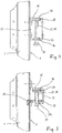
- FIG. 3 This shows Fig. 3 one of the two rails 10 in the area of their screw connection to a vertical support 1 of the frame. It can be seen in particular that a first rail segment 11 and a second rail segment 12 abut one another in this screw connection area.
- the abutment should be such that the running surface 15, which is formed by the upper profile sections 16 of the rail segments 11, 12, is designed as continuous as possible, i.e. without a step and without a significant height offset of the running surface 15 on the rail segment 11 to the running surface 15 the rail segment 12.
- the precision of the profiles forming the rail segments 11, 12 is subject to fluctuations. It is true that the metal sheets used for the production of the rail segments are of good dimensional accuracy with regard to their sheet metal thickness. However, they show by folding the rail segments produced by the sheet metal have a certain spread of their profile cross-sections.
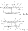
- the Figure 6a illustrates this.
- the total height of the left in Figure 6a The rail segment 11 shown is slightly lower than the total height of the other rail segment 12 due to the manufacturing process. This results in at least a slight step in the joint area when both rail segments 11, 12 are attached with their underside on a common bracket 14 that is fixed to the frame.
- the running surfaces 15 having a height offset are driven over, the distribution vehicle reproduced on the basis of its roller 8 vibrates.
- the arrangement is such that the pressure distribution bar 20 is supported with part of its length against the rear side 17 facing away from the running surface 15 on the first rail segment 11, and with the remaining part of its length against the rear side 17 facing away from the running surface 15 on the second rail segment 12 . Therefore, only the sheet metal thickness of the profile section 16 is located between the pressure distribution bar 20 and the running surface 15 their pure material thickness, d. H. concerns their sheet metal thickness.
- the pressure distribution strip 20 with its straight, flat upper side therefore forms a "smoothing" compensating element which, when pressure is exerted, is supported from below against that profile section 16 which forms the running surface 15 on its upper side.
- the prerequisite for the effectiveness of the pressure distribution strip 20 is that its upper side is essentially flat and of a width that is at most equal to the width of the running surface 15, and that it is subject to an upward pressure load.
- This pressure load is achieved by pressure transmission elements 21, which are shown in FIG Figure 6b are only shown schematically by means of vertical pressure arrows. Concrete exemplary embodiments of the pressure transmission elements 21 are described below with reference to FIG Figures 2 to 5 reproduced.
- the two rail segments 11, 12 are of C-shaped profile cross-section, as in FIG Fig. 1 reproduced.
- the two rail segments 11, 12 are screwed directly onto the vertical support 1 of the frame 3 by means of screws 27.
- the console 30 is z. B. of S-shaped cross-section. It is of such a length in the longitudinal direction of the rail that part of its length is in the rail segment 11 and the remaining part of its length is in the rail segment 12.
- the console 30 is a short profile which is firmly connected to both rail segments 11, 12.
- the bracket 30 is connected to profile sections 31, which protrude downward from the profile sections 16 forming the running surface 15, by a first screw connection 30A.
- the console 30 is connected to the vertical profile sections 13, which are fastened to the frame 3, by a second screw connection 30B.
- the screw connections 30A, 30B are made by means of screws which pass through openings in the bracket 30, in the profile sections 31 and 13 of the rail segments and also through openings in the support 1.
- the console 30 seated in both rail segments 11, 12 forms with the rail segments 11, 12 an assembly that is solid but not necessarily completely rigid.
- the bracket 30 forms the required abutment 22 when the pressure distribution strip 20 is pressed against the profile section 16.
- a screw 40 serves as an adjustable pressure transmission element 21 on each of the rail segments 11, 12. Its thread is screwed to a corresponding internal thread on the bracket 30.
- the end face of each screw 40 is supported in order to exert pressure against the pressure distribution strip 20, which in the exemplary embodiment has an underside, which extends parallel to the top.
- the pressure distribution bar 20 is designed here as an elongated cuboid.
- the internal thread on the console 30 serves as an abutment 22.
- a lower profile section 36 of the segments 11, 12 is provided as an extension of the screw 40 with an opening 37 for the tool to pass through.
- the console 30 can be of the same length as the pressure distribution strip 20 or of greater or lesser length. However, both the console 30 and the pressure distribution strip 20 are shorter than the rail segments 11, 12, since they only extend over the end regions of the rail segments 11, 12.
- the console 30 extends partly in one, partly in the other rail segment.
- Fig. 4 a second, significantly simplified embodiment is shown.
- the rail segments 11, 12 are here each screwed to the frame 3, closed rectangular hollow profiles.
- the pressure transmission elements 21 supported against the common pressure distribution strip 20 are in turn screws 40.
- the abutment 22 fixed to the frame is not located on an additional bracket, but on the lower profile section 36 of the rectangular profile.
- a nut is welded on the inside of the profile section 36, on which the internal thread for adjusting the screw 40 is located.
- the screws 40 press with their other end from below against the common pressure distribution strip 20, which in turn is supported on the rear side 17 of those profile sections 16 which form the running surfaces 15 at the top.
- a third embodiment is shown. It is characterized by simple assembly and the fact that the overall height of the rail segments including the console 30 serving as an abutment is relatively low.
- the rail segments 11, 12 are here from a cross-section open at the bottom.
- a short horizontal profile section 31A of the segments forms a support on which the console 30 is supported with its one longitudinal edge, while the console 30 is suspended in the vertical support 1 at its other longitudinal edge.
- the console 30 is therefore mounted without screw connections.
- the support 1 is provided with corresponding openings.
- the bracket 30 is provided with an internal thread which forms the actual abutment 22 and in which the screw 40 serving as a pressure transmission element 21 engages with its external thread.
- the console 30 optionally extends over the end regions of both rail segments 11, 12, or there are two separate consoles 30, one console only being in one rail segment 11 and the other console only in the other rail segment 12. But again, the pressure distribution bar 20 is continuous, as in FIG Figure 6b reproduced.
Landscapes
- Engineering & Computer Science (AREA)
- Mechanical Engineering (AREA)
- Warehouses Or Storage Devices (AREA)
- Fittings On The Vehicle Exterior For Carrying Loads, And Devices For Holding Or Mounting Articles (AREA)
Description
Die Erfindung betrifft ein Warenlager, insbesondere Shuttlelager, mit einem aus Profilelementen zusammengesetzten Gestell für die Warenlagerung und mit mindestens einer Gasse für den Transport ein- und auszulagernder Waren mittels eines auf Schienen längs der Gasse verfahrbaren Verteilerfahrzeuges, wobei die Schienen an dem Gestell befestigt sind und jeweils aus in Schienenlängsrichtung aufeinanderfolgenden Schienensegmenten zusammengesetzt sind, wobei die Schienensegmente jeweils Profile mit einem Profilabschnitt sind, dessen Oberseite die Lauffläche für das Verteilerfahrzeug bildet.The invention relates to a warehouse, in particular a shuttle warehouse, with a frame composed of profile elements for storing goods and with at least one aisle for the transport of goods to be stored and retrieved by means of a distribution vehicle that can be moved on rails along the aisle, the rails being fastened to the frame and are each composed of successive rail segments in the longitudinal direction of the rail, the rail segments each being profiles with a profile section, the upper side of which forms the running surface for the distribution vehicle.
Shuttlelager, wie sie z. B. aus der
Zur Geräuschentwicklung tragen aber nicht nur die in den Laufflächen verbauten Verbindungselemente bei. Auch die im Bereich des Aneinandergrenzens der Schienensegmente häufig vorhandenen Stöße führen zu einer Geräuschentwicklung und außerdem zu einer Erschütterung des Verteilerfahrzeuges und der darauf angeordneten Ladung während des Überfahrens der Schienenstöße. Denn in der Praxis unterliegt die Maßhaltigkeit der als Profile ausgebildeten Schienen und Schienensegmente deutlichen Schwankungen.However, it is not only the connecting elements built into the running surfaces that contribute to the development of noise. The shocks often present in the area where the rail segments adjoin one another also lead to noise development and also to a vibration of the distribution vehicle and the load arranged on it during the Driving over the rail joints. In practice, the dimensional accuracy of the rails and rail segments designed as profiles is subject to significant fluctuations.
Bei dem Warenlager gemäß der
Das Dokument
Der Erfindung liegt die Aufgabe zugrunde, bei einem Shuttlelager durch konstruktive Maßnahmen Geräusche und Erschütterungen im Bereich aufeinanderfolgender Schienensegmente zu reduzieren, die ansonsten bei dem Überfahren durch das Verteilerfahrzeug ("Shuttle") auftreten würden.The invention is based on the object of using structural measures to reduce noise and vibrations in the area of successive rail segments in a shuttle warehouse which would otherwise occur when the distribution vehicle ("shuttle") drives over it.
Zur Lösung dieser Aufgabe wird bei einem Warenlager mit den eingangs angegebenen Merkmalen vorgeschlagen, dass eine im Bereich zweier aufeinanderfolgender Schienensegmente angeordnete Druckverteilerleiste mit einem Teil ihrer Länge gegen den die Lauffläche bildenden Profilabschnitt des ersten Schienensegments, und mit dem übrigen Teil ihrer Länge gegen den die Lauffläche bildenden Profilabschnitt des zweiten Schienensegments abgestützt ist, und dass mindestens ein Druckübertragungselement einerseits von unten gegen die Druckverteilerleiste und andererseits gegenüber einem in Bezug auf das Gestell starr angeordneten Widerlager abgestützt istTo solve this problem, it is proposed in a warehouse with the features specified at the outset that a pressure distribution strip arranged in the area of two successive rail segments should have part of its length against the profile section of the first rail segment forming the running surface, and the remaining part of its length against the running surface forming profile section of the second rail segment is supported, and that at least one pressure transmission element is supported on the one hand from below against the pressure distribution strip and on the other hand against an abutment rigidly arranged with respect to the frame
Die Druckverteilerleiste stützt sich an den Unterseiten jener Profilabschnitte der zwei Schienensegmente ab, an denen oben die Laufflächen für das darauf rollende Verteilerfahrzeug ausgebildet sind. Die Laufflächen sind frei von Öffnungen für Befestigungsschrauben.The pressure distribution bar is supported on the undersides of those profile sections of the two rail segments on which the running surfaces for the distribution vehicle rolling on it are formed at the top. The running surfaces are free of openings for fastening screws.
Die Druckverteilerleiste ist mit einem nach oben gerichteten Druck beaufschlagt. Durch diese Maßnahmen werden die die Laufflächen für das darauf rollende Verteilerfahrzeug bildenden Profilabschnitte in eine gegenseitige Fluchtung gebracht, und zwar ohne dass sich in den Laufflächen Befestigungselemente wie z. B. Schrauben oder deren Öffnungen befinden müssen. Vielmehr verlaufen die Laufflächen auch im Stoßbereich der aufeinanderfolgenden Schienensegmente flach und eben, wodurch das darauf rollende Verteilerfahrzeug ein ruhiges und erschütterungsfreies Laufverhalten zeigt.The pressure distribution bar is subjected to an upward pressure. By means of these measures, the profile sections forming the treads for the distribution vehicle rolling on it are brought into mutual alignment without the need for fastening elements such as, for example, in the treads. B. screws or their openings must be located. Rather, the running surfaces also run flat and level in the joint area of the successive rail segments, as a result of which the distribution vehicle rolling on them shows a smooth and vibration-free running behavior.
Zwar ist die Ebenheit der Laufflächen zwangsläufig dort unterbrochen, wo benachbarte Schienensegmente aneinanderstoßen. Jedoch befindet sich an diesen Stoßbereichen kein nennenswerter Höhenversatz zwischen der Lauffläche des einen und der Lauffläche des anderen beteiligten Schienensegments. Vielmehr ist ein Höhenversatz der die Laufflächen aufweisenden Profilabschnitte durch die Wirkung der druckbelasteten Druckverteilerleiste unterbunden. Denn die Druckverteilerleiste ist mit einem Teil Ihrer Länge gegen die der Lauffläche abgewandte Seite des ersten Schienensegments, und mit dem übrigen Teil ihrer Länge gegen die der Lauffläche abgewandte Seite des zweiten beteiligten Schienensegments abgestützt. Entscheidend ist eine nach oben gerichtete, dauernde Druckkraft auf die an ihrer Oberseite vorzugsweise flach und eben gestaltete Druckverteilerleiste.It is true that the flatness of the running surfaces is inevitably interrupted where adjacent rail segments meet. However, in these joint areas there is no significant height offset between the running surface of one rail segment and the running surface of the other rail segment involved. Rather, a height offset of the profile sections having the running surfaces is prevented by the effect of the pressure-loaded pressure distribution bar. Because the pressure distribution bar is supported with part of its length against the side of the first rail segment facing away from the running surface, and with the remaining part of its length against the side of the second participating rail segment facing away from the running surface. The decisive factor is an upwardly directed, permanent pressure force on the pressure distribution strip, which is preferably flat and level on its upper side.
Diese dauernde Druckkraft wird erzielt, indem mindestens ein Druckübertragungselement, welches vorzugsweise selbst starr ausgebildet ist, einerseits von unten gegen die Druckverteilerleiste abgestützt ist, und dasselbe Druckübertragungselement andererseits gegenüber einem Widerlager abgestützt ist, wobei das Widerlager starr in Bezug auf das Gestell des Warenlagers angeordnet ist. Auch die Schienensegmente sind gestellfest befestigt, z. B. indem sie direkt an vertikalen Stützen des Gestells angeschraubt sind.This permanent pressure force is achieved in that at least one pressure transmission element, which is preferably itself rigid, is supported on the one hand from below against the pressure distribution bar, and the same pressure transmission element is supported on the other hand against an abutment, the abutment being arranged rigidly in relation to the frame of the goods store . The rail segments are also fixed to the frame, e.g. B. by screwing them directly to vertical supports of the frame.
Wo sich das Widerlager befindet, ist nicht entscheidend, solange es gestellfest ist. Zum Beispiel kann sich das Widerlager an einem anderen Profilabschnitt desselben Schienensegments befinden.Where the abutment is located is not critical as long as it is fixed to the frame. For example, the abutment can be located on a different profile section of the same rail segment.
Als Schienen dienen Profile aus zumindest einmal abgekantetem Metallblech. Die Praxis hat gezeigt, dass die Fertigungspräzision dieser industriell gefertigten Schienen Schwankungen unterliegt. Zwar sind die verwendeten Metallbleche von guter Maßhaltigkeit, was ihre Materialdicke, d.h. Blechdicke betrifft. Jedoch zeigen die durch Abkanten der Metallbleche geformten Profile eine Streuung ihrer Profilquerschnitte. Daher liegt der Erfindung die Erkenntnis zugrunde, dass im Stoßbereich zwischen aufeinanderfolgenden Schienensegmenten vorhandene Ungenauigkeiten eher auf mangelnde Maßhaltigkeit der Profilquerschnitte zurückzuführen ist, denn auf Schwankungen in der Materialdicke des Metallblechs, aus dem die Schienensegmente bestehen.Profiles made of sheet metal that have been folded at least once serve as rails. Practice has shown that the manufacturing precision of these industrially manufactured rails is subject to fluctuations. The metal sheets used are of good dimensional accuracy in terms of their material thickness, i.e. sheet thickness. However, the profiles formed by folding the metal sheets show a scatter in their profile cross-sections. The invention is therefore based on the knowledge that inaccuracies present in the joint area between successive rail segments are more likely to be attributed to insufficient dimensional accuracy of the profile cross-sections than to fluctuations in the material thickness of the sheet metal from which the rail segments are made.
Mit den hier beschriebenen Maßnahmen werden daher stoßfreie Übergänge zwischen den Laufflächen aufeinanderfolgender Schienensegmente der Schiene erreicht.With the measures described here, seamless transitions between the running surfaces of successive rail segments of the rail are therefore achieved.
Mit einer Ausgestaltung wird vorgeschlagen, dass das Druckübertragungselement hinsichtlich seiner Länge und/oder seiner Position in Richtung senkrecht zur Lauffläche einstellbar ausgebildet ist. Vorzugsweise ist das Druckübertragungselement eine Schraube oder ein Schraubbolzen.With one embodiment it is proposed that the pressure transmission element be designed to be adjustable in terms of its length and / or its position in the direction perpendicular to the running surface is. The pressure transmission element is preferably a screw or a screw bolt.
Gemäß einer Ausgestaltung befindet sich das Widerlager, an dem sich das Druckübertragungselement abzustützen vermag, an einer Konsole. Die Konsole ist mit dem Schienensegment zumindest in Richtung senkrecht zur Lauffläche verbunden.According to one embodiment, the abutment on which the pressure transmission element is able to be supported is located on a console. The console is connected to the rail segment at least in the direction perpendicular to the running surface.
Ferner sieht eine Ausgestaltung vor, dass die Schienensegmente einen von dem die Lauffläche bildenden Profilabschnitt nach unten führenden, weiteren Profilabschnitt aufweisen, mit dem die Konsole verbunden ist.Furthermore, one embodiment provides that the rail segments have a further profile section leading down from the profile section forming the running surface, to which the bracket is connected.
Kommen im Bereich der Verbindung der zwei Schienensegmente zwei Konsolen zum Einsatz, so ist die erste Konsole nur mit dem ersten Schienensegment und die zweite Konsole nur mit dem zweiten Schienensegment verbunden.If two consoles are used in the area where the two rail segments are connected, the first console is only connected to the first rail segment and the second console is only connected to the second rail segment.
Bevorzugt wird jedoch eine Bauform, bei der im Bereich der Verbindung der zwei Schienensegmente nur eine einzige Konsole zum Einsatz kommt, wobei diese Konsole sowohl mit dem ersten Schienensegment als auch mit dem zweiten Schienensegment verbunden ist.However, a design is preferred in which only a single bracket is used in the area of the connection of the two rail segments, this bracket being connected to both the first rail segment and the second rail segment.
Gemäß einer bevorzugten Ausgestaltung ist jedes Schienensegment mit einem daran ausgebildeten Befestigungsabschnitt unmittelbar gegen eine Montagefläche des Gestells befestigt, an der die Konsole nur mittelbar unter Zwischenlage des Befestigungsabschnitts befestigt ist.According to a preferred embodiment, each rail segment is fastened with a fastening section formed thereon directly against a mounting surface of the frame to which the console is fastened only indirectly with the fastening section being interposed.
Eine weitere Ausgestaltung ist gekennzeichnet durch insgesamt zwei Druckübertragungselemente, die einerseits beide gegen die Druckverteilerleiste abgestützt sind und die andererseits an getrennten Widerlagern abgestützt sind, von denen das erste Widerlager auf der Länge des ersten Schienensegments, und das zweite Widerlager auf der Länge des zweiten Schienensegments angeordnet ist.Another embodiment is characterized by a total of two pressure transmission elements, both of which are supported on the one hand against the pressure distribution bar and on the other hand are supported on separate abutments, of which the first abutment is arranged on the length of the first rail segment and the second abutment on the length of the second rail segment is.
Ausführungsbeispiele werden nachfolgend anhand der zugehörigen Figuren näher erläutert. Darin zeigen:
- Fig. 1
- ein Warenlager und insbesondere Shuttlelager mit einem aus Profilelementen zusammengesetzten Gestell einschließlich einer Gasse für den Transport der ein- und auszulagernden Waren, wobei sich in der Gasse ein längs der Gasse verfahrbares, auf Laufrollen abgestütztes Verteilerfahrzeug befindet;
- Fig. 2
- die in
Fig. 1 bezeichnete Einzelheit II, nämlich der Bereich der Befestigung einer Schiene, welche die Lauffläche für das Verteilerfahrzeug bildet, an einer Stütze des Gestells; - Fig. 3
- eine Ansicht der Schiene und der Stütze entsprechend der in
Fig. 1 eingezeichneten Blickrichtung III-III; - Fig. 4
- eine zweite Ausführungsform, wobei die Wiedergabe analog jener der
Fig. 2 ist; - Fig. 5
- eine dritte Ausführungsform, wobei die Wiedergabe analog jener der
Fig. 2 ist; - Fig. 6a
- eine Prinzipdarstellung, welche das der Erfindung zugrunde liegende Problem illustriert;
- Fig. 6b
- eine Prinzipdarstellung der technischen Lösung, wie sie hier vorgeschlagen wird.
- Fig. 1
- a warehouse and in particular a shuttle warehouse with a frame composed of profile elements including an alley for the transport of the goods to be stored and retrieved, with a distribution vehicle being located in the alley, which can be moved along the aisle and is supported on rollers;
- Fig. 2
- in the
Fig. 1 designated detail II, namely the area of the fastening of a rail, which forms the running surface for the distribution vehicle, on a support of the frame; - Fig. 3
- a view of the rail and the support according to the in
Fig. 1 indicated direction of view III-III; - Fig. 4
- a second embodiment, the reproduction analogous to that of
Fig. 2 is; - Fig. 5
- a third embodiment, the reproduction analogous to that of
Fig. 2 is; - Figure 6a
- a schematic diagram illustrating the problem on which the invention is based;
- Figure 6b
- a schematic diagram of the technical solution as proposed here.
Die
Das Gestell 3 des Warenlagers setzt sich aus einer Vielzahl von Profilelementen 1, 2 zusammen. Zu diesen Profilelementen gehören vertikale Träger 1, welche die statische Grundstruktur des Warenlagers bilden, sowie horizontale Stützen oder Traversen 2, welche an den vertikalen Stützen 1 befestigt sind. Zu den Profilelementen des Gestells 3 gehören ferner Warenauflagen für die gelagerten Waren 7. Des Weiteren können zur Versteifung des Gestells 3 noch querverlaufende oder diagonale Profilelemente vorhanden sein.The
Das Ein- und Auslagern der einzelnen Waren 7 erfolgt über die Gasse 6, in der das Verteilerfahrzeug 5 längs verfahrbar ist. Die
Das Verteilerfahrzeug 5 rollt auf Rollen 8, die zumindest zum Teil angetriebene Rollen sind. Üblicherweise verfügen derartige Verteilerfahrzeuge 5 über insgesamt vier Rollen 8, von denen zwei auf der linken, und zwei auf der rechten Fahrzeugseite angeordnet sind.The
Zur Abstützung und zur seitlichen Führung der Rollen 8 sind in der Gasse 6 paarweise vorhandene Schienen 10 angeordnet. Die eine Schiene 10 befindet sich an der einen Seite der Gasse, und die andere Schiene 10 an der anderen Seite der Gasse. Die Schienen 10 sind an dem Gestell 3 des Warenlagers befestigt. Bevorzugt erfolgt die Befestigung der Schienen 10 an den dafür statisch besonders geeigneten vertikalen Stützen 1, z. B. mittels Schrauben.To support and to guide the
Als Schienen 10 dienen Profile, die sich teils aus horizontalen und teils aus vertikalen Profilabschnitten zusammensetzen. Die Profile können geschlossene Profile oder Hohlprofile sein, oder offene Profile wie z. B. L-förmige oder S-förmige Profile. Bei dem hier ersten Ausführungsbeispiel sind die Schienen 10 als Profile von C-förmigem Querschnitt gestaltet, wobei ein vertikaler Profilabschnitt 13 der Schiene 10 an den Stützen 1 befestigt ist, wohingegen die offene Profilseite zu der Gasse 6 hin weist. Ein horizontaler Profilabschnitt 16 der Schiene 10 bildet mit seiner flachen Oberseite die Lauffläche 15 für die Rollen 8 des Shuttles.Profiles which are composed partly of horizontal and partly of vertical profile sections serve as rails 10. The profiles can be closed profiles or hollow profiles, or open profiles such. B. L-shaped or S-shaped profiles. In the first exemplary embodiment here, the
Jede Schiene 10 ist insgesamt von erheblicher Länge, weshalb es montagetechnisch sinnvoll ist, die Schiene 10 zu segmentieren, d. h. in einzelne, aufeinanderfolgende Schienensegmente zu unterteilen.Each
Hierzu zeigt
In der Praxis unterliegt die Präzision der die Schienensegmente 11, 12 bildenden Profile Schwankungen. Zwar sind die für die Herstellung der Schienensegmente verwendeten Metallbleche von guter Maßhaltigkeit, was ihre Blechdicke betrifft. Jedoch zeigen die durch Abkanten der Metallbleche hergestellten Schienensegmente eine gewisse Streuung ihrer Profilquerschnitte.In practice, the precision of the profiles forming the
Die
Anders verhält es sich bei den in
Die Anordnung ist dergestalt, dass sich die Druckverteilerleiste 20 mit einem Teil ihrer Länge gegen die der Lauffläche 15 abgewandte Rückseite 17 an dem ersten Schienensegment 11, und mit dem übrigen Teil ihrer Länge gegen die der Lauffläche 15 abgewandte Rückseite 17 an dem zweiten Schienensegment 12 abstützt. Zwischen der Druckverteilerleiste 20 und der Lauffläche 15 befindet sich daher nur die Blechdicke des Profilabschnitts 16. Die Maßhaltigkeit der Blechdicke ist allerdings gut, da sich gezeigt hat, dass die zum Herstellen der Schienensegmente 11, 12 verwendeten Metallbleche fast immer von guter Maßhaltigkeit sind, was ihre reine Materialdicke, d. h. ihre Blechdicke betrifft.The arrangement is such that the
Die Druckverteilerleiste 20 bildet daher mit ihrer geraden, flachen Oberseite ein "glättendes" Ausgleichselement, welches sich unter Druckausübung von unten gegen jenen Profilabschnitt 16 abstützt, der auf seiner Oberseite die Lauffläche 15 bildet. Voraussetzung für die Wirksamkeit der Druckverteilerleiste 20 ist, dass ihre Oberseite im Wesentlichen flach ist und von einer Breite, die maximal gleich der Breite der Lauffläche 15 ist, und dass sie einer nach oben gerichteten Druckbelastung unterliegt. Diese Druckbelastung wird durch Druckübertragungselemente 21 erreicht, die in
Es ist nicht zwingend dass, wie in
In den
Im Verbindungsbereich der Schienensegmente 11, 12 ist in diese eine Konsole 30 eingesetzt. Die Konsole 30 ist z. B. von S-förmigem Querschnitt. Sie ist in Schienenlängsrichtung von solcher Länge, dass sie sich mit einem Teil ihrer Länge in dem Schienensegment 11, und mit dem übrigen Teil ihre Länge in dem Schienensegment 12 befindet.In the connection area of the
Die Konsole 30 ist ein kurzes Profil, welches fest mit beiden Schienensegmenten 11, 12 verbunden ist. Die Konsole 30 ist mit Profilabschnitten 31, welche von den die Lauffläche 15 bildenden Profilabschnitten 16 nach unten ragen, durch eine erste Verschraubung 30A verbunden. Außerdem ist die Konsole 30 mit den vertikalen Profilabschnitten 13, welche an dem Gestell 3 befestigt sind, durch eine zweite Verschraubung 30B verbunden. Die Verschraubungen 30A, 30B erfolgen mittels Schrauben, welche durch Öffnungen in der Konsole 30, in den Profilabschnitten 31 und 13 der Schienensegmente und außerdem durch Öffnungen in der Stütze 1 hindurchführen.The
Die in beiden Schienensegmenten 11, 12 sitzende Konsole 30 bildet mit den Schienensegmenten 11, 12 eine zwar feste aber nicht unbedingt gänzlich starre Baugruppe. In dieser Baugruppe bildet die Konsole 30 das erforderliche Widerlager 22 beim Andrücken der Druckverteilerleiste 20 gegen den Profilabschnitt 16.The
Als einstellbares Druckübertragungselement 21 dient an jedem der Schienensegmente 11, 12 jeweils eine Schraube 40. Deren Gewinde ist mit einem entsprechenden Innengewinde an der Konsole 30 verschraubt. Die Stirnseite jeder Schraube 40 ist zur Druckausübung gegen die Druckverteilerleiste 20 abgestützt, die bei dem Ausführungsbeispiel eine Unterseite aufweist, die sich parallel zu der Oberseite erstreckt. Die Druckverteilerleiste 20 ist hier als ein länglicher Quader gestaltet.A
Als Widerlager 22 dient das Innengewinde an der Konsole 30. Zum Verdrehen der Schraube 40 und damit Einstellen des Drucks auf die Druckverteilerleiste 20 ist die Schraube 40 an ihrem anderen, unteren Ende mit Schlüsselflächen 41 zum Ansetzen eines geeigneten Werkzeugs, z. B. eines Innensechskantschlüssels, versehen. Ein unterer Profilabschnitt 36 der Segmente 11, 12 ist in Verlängerung der Schraube 40 mit einer Öffnung 37 für das Hindurchführen des Werkzeugs versehen.The internal thread on the
Die Konsole 30 kann von gleicher Länge sein wie die Druckverteilerleiste 20 oder von größerer oder geringerer Länge. Jedoch sind sowohl die Konsole 30, als auch die Druckverteilerleiste 20 kürzer als die Schienensegmente 11, 12, da sie sich nur über die Endbereiche der Schienensegmente 11, 12 erstrecken.The
Bei der Ausführungsform nach
In
Wie bei der ersten Ausführungsform drücken die Schrauben 40 mit ihrem anderen Ende von unten gegen die gemeinsame Druckverteilerleiste 20, welche sich wiederum an der Rückseite 17 jener Profilabschnitte 16 abstützt, welche oben die Laufflächen 15 bilden.As in the first embodiment, the
In
Zum Einhängen der mit Haken versehenen Konsole 30 ist die Stütze 1 mit entsprechenden Öffnungen versehen. Wiederum ist die Konsole 30 mit einem Innengewinde versehen, welches das eigentliche Widerlager 22 bildet und in welches die als Druckübertragungselement 21 dienende Schraube 40 mit ihrem Außengewinde eingreift.To hang the
Die Konsole 30 erstreckt sich wahlweise über die Endbereiche beider Schienensegmente 11, 12, oder es sind zwei getrennte Konsolen 30 vorhanden, wobei sich die eine Konsole nur in dem einen Schienensegment 11, und die andere Konsole nur in dem anderen Schienensegment 12 befindet. Aber wiederum ist die Druckverteilerleiste 20 durchgehend, wie in
- 11
- Stützesupport
- 22
- horizontaler Träger, Traversehorizontal beam, traverse
- 33
- Gestellframe
- 55
- Verteilerfahrzeug, ShuttleDistribution vehicle, shuttle
- 66th
- Gassealley
- 77th
- WareWere
- 88th
- Rollerole
- 1010
- Schienerail
- 1111
- SchienensegmentRail segment
- 1212th
- SchienensegmentRail segment
- 1313th
- vertikaler Profilabschnitt, Befestigungsabschnittvertical profile section, fastening section
- 1414th
- Konsoleconsole
- 1515th
- LaufflächeTread
- 1616
- ProfilabschnittProfile section
- 1717th
- Rückseite (Unterseite)Back (bottom)
- 2020th
- DruckverteilerleistePressure distribution strip
- 2121
- DruckübertragungselementPressure transmission element
- 2222nd
- WiderlagerAbutment
- 2727
- SchraubenScrews
- 3030th
- Konsoleconsole
- 30A30A
- VerschraubungScrew connection
- 30B30B
- VerschraubungScrew connection
- 3131
- weiterer Profilabschnittfurther profile section
- 31A31A
- horizontaler Profilabschnitthorizontal profile section
- 3636
- unterer Profilabschnittlower profile section
- 3737
- Öffnungopening
- 4040
- Schraubescrew
- 4141
- SchlüsselflächeWrench flat
Claims (9)
- Warehouse, in particular shuttle warehouse, having a rack (3), composed of profile elements, for the warehousing, and having at least one aisle (6) for the transport of goods (7), which are to be stored and retrieved, by means of a distribution vehicle (5) which is movable along the aisle (6) on rails (10), wherein the rails (10) are fastened to the rack (3) and are respectively composed of rail segments (11, 12) following one upon another in the longitudinal direction of the rail, wherein the rail segments (11, 12) are respectively profiles having a profile section (16) whose top side forms the running surface (15) for the distribution vehicle (5), wherein a pressure distribution bar (20) arranged in the region of two successive rail segments (11, 12) is supported with a part of its length against that profile section (16) of the first rail segment (11) that forms the running surface (15), and with the remaining part of its length against that profile section (16) of the second rail segment (12) that forms the running surface (15), and characterized in that at least one pressure transmission element (21) is supported, on the one hand, from below against the pressure distribution bar (20) and, on the other hand, against a counter bearing (22) arranged rigidly with respect to the rack (3).
- Warehouse according to Claim 1, characterized in that the pressure transmission element (21) is configured such that it is adjustable in terms of its length and/or its position in a direction perpendicular to the running surface (15).
- Warehouse according to Claim 2, characterized by a screw (40) or a stud bolt as the pressure transmission element (21).
- Warehouse according to one of the preceding claims, characterized in that the counter bearing (22) is located on a bracket (30), which is connected to the rail segment (11, 12) at least in a direction perpendicular to the running surface (15).
- Warehouse according to Claim 4, characterized in that the rail segments (11, 12) have a further profile section (31), which leads downwards from the profile section (16) forming the running surface (15) and to which the bracket (30) is connected.
- Warehouse according to Claim 4 or 5, characterized by two brackets (30), wherein the first bracket is connected only to the first rail segment (11), and the second bracket only to the second rail segment (12).
- Warehouse according to Claim 4 or 5, characterized in that the bracket (30) is connected both to the first rail segment (11) and to the second rail segment (12).
- Warehouse according to Claim 7, characterized in that each rail segment (11, 12) is fastened with a thereon configured fastening portion (13) directly against a mounting surface of the rack (3), to which mounting surface the bracket (30) is fastened only indirectly, with the interposition of the fastening portion (13).
- Warehouse according to one of the preceding claims, characterized by, in total, two pressure transmission elements (21), which, on the one hand, are both supported against the pressure distribution bar (20) and which, on the other hand, are supported against separate counter bearings (22), of which the counter bearing (22) is arranged on the length of the first rail segment (11), and the second counter bearing (22) on the length of the second rail segment (12).
Priority Applications (1)
| Application Number | Priority Date | Filing Date | Title |
|---|---|---|---|
| PL20155142T PL3699112T3 (en) | 2019-02-21 | 2020-02-03 | Warehouse, especially shuttle warehouse |
Applications Claiming Priority (1)
| Application Number | Priority Date | Filing Date | Title |
|---|---|---|---|
| DE102019104372.7A DE102019104372A1 (en) | 2019-02-21 | 2019-02-21 | Warehouses, in particular shuttle warehouses |
Publications (2)
| Publication Number | Publication Date |
|---|---|
| EP3699112A1 EP3699112A1 (en) | 2020-08-26 |
| EP3699112B1 true EP3699112B1 (en) | 2021-10-06 |
Family
ID=69467417
Family Applications (1)
| Application Number | Title | Priority Date | Filing Date |
|---|---|---|---|
| EP20155142.1A Active EP3699112B1 (en) | 2019-02-21 | 2020-02-03 | Warehouse, especially shuttle warehouse |
Country Status (7)
| Country | Link |
|---|---|
| US (1) | US11286112B2 (en) |
| EP (1) | EP3699112B1 (en) |
| CA (1) | CA3070165A1 (en) |
| DE (1) | DE102019104372A1 (en) |
| DK (1) | DK3699112T3 (en) |
| ES (1) | ES2902492T3 (en) |
| PL (1) | PL3699112T3 (en) |
Cited By (1)
| Publication number | Priority date | Publication date | Assignee | Title |
|---|---|---|---|---|
| WO2024023090A1 (en) | 2022-07-28 | 2024-02-01 | Nedcon B.V. | Warehouse for the storage and retrieval of goods or bundles of goods arranged on load carriers |
Families Citing this family (5)
| Publication number | Priority date | Publication date | Assignee | Title |
|---|---|---|---|---|
| WO2021220686A1 (en) * | 2020-04-30 | 2021-11-04 | 村田機械株式会社 | Traveling platform, and automatic storehouse |
| PL3992116T3 (en) * | 2020-10-27 | 2025-04-22 | Stow International N.V. | AUTOMATED SLIDING RACK SYSTEM FOR SMALL PARTS |
| DE102021110715A1 (en) * | 2021-04-27 | 2022-10-27 | Nedcon B.V. | Warehouse with passable lanes |
| NO346915B1 (en) * | 2021-05-27 | 2023-02-27 | Autostore Tech As | Rail Joint |
| US11772893B1 (en) * | 2021-11-23 | 2023-10-03 | Amazon Technologies, Inc. | Transition components for gaps in shuttle rails |
Family Cites Families (7)
| Publication number | Priority date | Publication date | Assignee | Title |
|---|---|---|---|---|
| IT1294287B1 (en) * | 1997-07-30 | 1999-03-24 | Fata Automation | CELL WAREHOUSE WITH HYDROPNEUMATIC HANDLING TRANSPORT WAGONS |
| AT511162A1 (en) * | 2011-02-08 | 2012-09-15 | Tgw Mechanics Gmbh | BAY WAREHOUSE SYSTEM |
| AT511623B1 (en) * | 2011-07-08 | 2016-01-15 | Tgw Mechanics Gmbh | BAY WAREHOUSE SYSTEM |
| US9173489B2 (en) * | 2013-05-23 | 2015-11-03 | Milton Mercy & Associates, Inc. | Storage rack divider kit and apparatus |
| DE102014114496A1 (en) * | 2014-10-07 | 2016-04-07 | Bito-Lagertechnik Bittmann Gmbh | Shelf storage with rails |
| DE102014114978B4 (en) * | 2014-10-15 | 2022-01-05 | Bito-Lagertechnik Bittmann Gmbh | Shelf storage |
| DE202016106276U1 (en) * | 2016-11-10 | 2016-12-09 | Bito-Lagertechnik Bittmann Gmbh | shuttle Available |
-
2019
- 2019-02-21 DE DE102019104372.7A patent/DE102019104372A1/en not_active Withdrawn
-
2020
- 2020-01-29 CA CA3070165A patent/CA3070165A1/en active Pending
- 2020-02-03 ES ES20155142T patent/ES2902492T3/en active Active
- 2020-02-03 PL PL20155142T patent/PL3699112T3/en unknown
- 2020-02-03 DK DK20155142.1T patent/DK3699112T3/en active
- 2020-02-03 EP EP20155142.1A patent/EP3699112B1/en active Active
- 2020-02-10 US US16/785,711 patent/US11286112B2/en active Active
Cited By (2)
| Publication number | Priority date | Publication date | Assignee | Title |
|---|---|---|---|---|
| WO2024023090A1 (en) | 2022-07-28 | 2024-02-01 | Nedcon B.V. | Warehouse for the storage and retrieval of goods or bundles of goods arranged on load carriers |
| DE102022119000A1 (en) | 2022-07-28 | 2024-02-08 | Nedcon B.V. | Warehouse for storing and retrieving goods or containers of goods arranged on load carriers |
Also Published As
| Publication number | Publication date |
|---|---|
| DE102019104372A1 (en) | 2020-08-27 |
| CA3070165A1 (en) | 2020-08-21 |
| US11286112B2 (en) | 2022-03-29 |
| ES2902492T3 (en) | 2022-03-28 |
| US20200270059A1 (en) | 2020-08-27 |
| PL3699112T3 (en) | 2022-02-14 |
| EP3699112A1 (en) | 2020-08-26 |
| DK3699112T3 (en) | 2022-01-03 |
Similar Documents
| Publication | Publication Date | Title |
|---|---|---|
| EP3699112B1 (en) | Warehouse, especially shuttle warehouse | |
| EP2850968B1 (en) | Piece goods warehouse | |
| EP1934120B1 (en) | Storage rack with a multiplicity of rack units | |
| DE3229601A1 (en) | INSULATION SHEET, ESPECIALLY MADE OF MINERAL FIBER FELT, WITH A GLUED LAMINATION, AND A METHOD FOR THEIR PRODUCTION AND METHOD FOR THEIR INSTALLATION | |
| EP3088347B1 (en) | Shelf serving device | |
| DE19752793A1 (en) | Telescopic device for heavy loads for e.g. motor pumps of Fire service vehicles | |
| DE69422292T2 (en) | UNIVERSAL CARRIER FOR A MOVING LOAD | |
| EP0329832B1 (en) | Frame for belt conveyors | |
| DE19544619C2 (en) | Sliding roof for a truck | |
| EP2010023A1 (en) | Shelf panel | |
| EP4175899A1 (en) | Warehouse for the storage and retrieval of goods or bundles of goods placed on load carriers | |
| EP0572929A1 (en) | Parking platform | |
| EP4703299A1 (en) | Warehouse for storing and retrieving goods or containers from load carriers | |
| EP3336048A1 (en) | Shelf serving device | |
| EP4330162B1 (en) | Goods warehouse with passable aisles | |
| EP0935932B1 (en) | Storage shelving, especially for the storage of loaded pallets | |
| EP1234785A1 (en) | Shelf storage | |
| AT525229B1 (en) | Scale for weighing a roll-off container | |
| EP0936160B1 (en) | Storage device for pallets or articles with a standardised base part | |
| DE3627841C2 (en) | ||
| EP3974349B1 (en) | Shuttle warehouse | |
| EP2226272B1 (en) | Shelving system | |
| DE102020120245B4 (en) | Carrier for a motor vehicle | |
| DE3503359C2 (en) | Industrial truck, especially stacker truck, also known as reach truck | |
| EP0074648A2 (en) | Frame for belt conveyor devices |
Legal Events
| Date | Code | Title | Description |
|---|---|---|---|
| PUAI | Public reference made under article 153(3) epc to a published international application that has entered the european phase |
Free format text: ORIGINAL CODE: 0009012 |
|
| STAA | Information on the status of an ep patent application or granted ep patent |
Free format text: STATUS: THE APPLICATION HAS BEEN PUBLISHED |
|
| AK | Designated contracting states |
Kind code of ref document: A1 Designated state(s): AL AT BE BG CH CY CZ DE DK EE ES FI FR GB GR HR HU IE IS IT LI LT LU LV MC MK MT NL NO PL PT RO RS SE SI SK SM TR |
|
| AX | Request for extension of the european patent |
Extension state: BA ME |
|
| STAA | Information on the status of an ep patent application or granted ep patent |
Free format text: STATUS: REQUEST FOR EXAMINATION WAS MADE |
|
| 17P | Request for examination filed |
Effective date: 20201207 |
|
| RBV | Designated contracting states (corrected) |
Designated state(s): AL AT BE BG CH CY CZ DE DK EE ES FI FR GB GR HR HU IE IS IT LI LT LU LV MC MK MT NL NO PL PT RO RS SE SI SK SM TR |
|
| GRAP | Despatch of communication of intention to grant a patent |
Free format text: ORIGINAL CODE: EPIDOSNIGR1 |
|
| STAA | Information on the status of an ep patent application or granted ep patent |
Free format text: STATUS: GRANT OF PATENT IS INTENDED |
|
| INTG | Intention to grant announced |
Effective date: 20210512 |
|
| GRAS | Grant fee paid |
Free format text: ORIGINAL CODE: EPIDOSNIGR3 |
|
| GRAA | (expected) grant |
Free format text: ORIGINAL CODE: 0009210 |
|
| STAA | Information on the status of an ep patent application or granted ep patent |
Free format text: STATUS: THE PATENT HAS BEEN GRANTED |
|
| AK | Designated contracting states |
Kind code of ref document: B1 Designated state(s): AL AT BE BG CH CY CZ DE DK EE ES FI FR GB GR HR HU IE IS IT LI LT LU LV MC MK MT NL NO PL PT RO RS SE SI SK SM TR |
|
| REG | Reference to a national code |
Ref country code: GB Ref legal event code: FG4D Free format text: NOT ENGLISH |
|
| REG | Reference to a national code |
Ref country code: CH Ref legal event code: EP Ref country code: AT Ref legal event code: REF Ref document number: 1436053 Country of ref document: AT Kind code of ref document: T Effective date: 20211015 |
|
| REG | Reference to a national code |
Ref country code: DE Ref legal event code: R096 Ref document number: 502020000232 Country of ref document: DE |
|
| REG | Reference to a national code |
Ref country code: IE Ref legal event code: FG4D Free format text: LANGUAGE OF EP DOCUMENT: GERMAN |
|
| REG | Reference to a national code |
Ref country code: FI Ref legal event code: FGE |
|
| REG | Reference to a national code |
Ref country code: DK Ref legal event code: T3 Effective date: 20211223 |
|
| REG | Reference to a national code |
Ref country code: SE Ref legal event code: TRGR |
|
| REG | Reference to a national code |
Ref country code: NL Ref legal event code: FP |
|
| REG | Reference to a national code |
Ref country code: DE Ref legal event code: R082 Ref document number: 502020000232 Country of ref document: DE Representative=s name: JANKE SCHOLL PATENTANWAELTE PARTG MBB, DE |
|
| REG | Reference to a national code |
Ref country code: LT Ref legal event code: MG9D |
|
| REG | Reference to a national code |
Ref country code: NO Ref legal event code: T2 Effective date: 20211006 |
|
| REG | Reference to a national code |
Ref country code: ES Ref legal event code: FG2A Ref document number: 2902492 Country of ref document: ES Kind code of ref document: T3 Effective date: 20220328 |
|
| PG25 | Lapsed in a contracting state [announced via postgrant information from national office to epo] |
Ref country code: RS Free format text: LAPSE BECAUSE OF FAILURE TO SUBMIT A TRANSLATION OF THE DESCRIPTION OR TO PAY THE FEE WITHIN THE PRESCRIBED TIME-LIMIT Effective date: 20211006 Ref country code: LT Free format text: LAPSE BECAUSE OF FAILURE TO SUBMIT A TRANSLATION OF THE DESCRIPTION OR TO PAY THE FEE WITHIN THE PRESCRIBED TIME-LIMIT Effective date: 20211006 Ref country code: BG Free format text: LAPSE BECAUSE OF FAILURE TO SUBMIT A TRANSLATION OF THE DESCRIPTION OR TO PAY THE FEE WITHIN THE PRESCRIBED TIME-LIMIT Effective date: 20220106 |
|
| PG25 | Lapsed in a contracting state [announced via postgrant information from national office to epo] |
Ref country code: IS Free format text: LAPSE BECAUSE OF FAILURE TO SUBMIT A TRANSLATION OF THE DESCRIPTION OR TO PAY THE FEE WITHIN THE PRESCRIBED TIME-LIMIT Effective date: 20220206 Ref country code: PT Free format text: LAPSE BECAUSE OF FAILURE TO SUBMIT A TRANSLATION OF THE DESCRIPTION OR TO PAY THE FEE WITHIN THE PRESCRIBED TIME-LIMIT Effective date: 20220207 Ref country code: LV Free format text: LAPSE BECAUSE OF FAILURE TO SUBMIT A TRANSLATION OF THE DESCRIPTION OR TO PAY THE FEE WITHIN THE PRESCRIBED TIME-LIMIT Effective date: 20211006 Ref country code: HR Free format text: LAPSE BECAUSE OF FAILURE TO SUBMIT A TRANSLATION OF THE DESCRIPTION OR TO PAY THE FEE WITHIN THE PRESCRIBED TIME-LIMIT Effective date: 20211006 Ref country code: GR Free format text: LAPSE BECAUSE OF FAILURE TO SUBMIT A TRANSLATION OF THE DESCRIPTION OR TO PAY THE FEE WITHIN THE PRESCRIBED TIME-LIMIT Effective date: 20220107 |
|
| REG | Reference to a national code |
Ref country code: DE Ref legal event code: R097 Ref document number: 502020000232 Country of ref document: DE |
|
| PG25 | Lapsed in a contracting state [announced via postgrant information from national office to epo] |
Ref country code: SM Free format text: LAPSE BECAUSE OF FAILURE TO SUBMIT A TRANSLATION OF THE DESCRIPTION OR TO PAY THE FEE WITHIN THE PRESCRIBED TIME-LIMIT Effective date: 20211006 Ref country code: SK Free format text: LAPSE BECAUSE OF FAILURE TO SUBMIT A TRANSLATION OF THE DESCRIPTION OR TO PAY THE FEE WITHIN THE PRESCRIBED TIME-LIMIT Effective date: 20211006 Ref country code: RO Free format text: LAPSE BECAUSE OF FAILURE TO SUBMIT A TRANSLATION OF THE DESCRIPTION OR TO PAY THE FEE WITHIN THE PRESCRIBED TIME-LIMIT Effective date: 20211006 Ref country code: EE Free format text: LAPSE BECAUSE OF FAILURE TO SUBMIT A TRANSLATION OF THE DESCRIPTION OR TO PAY THE FEE WITHIN THE PRESCRIBED TIME-LIMIT Effective date: 20211006 Ref country code: CZ Free format text: LAPSE BECAUSE OF FAILURE TO SUBMIT A TRANSLATION OF THE DESCRIPTION OR TO PAY THE FEE WITHIN THE PRESCRIBED TIME-LIMIT Effective date: 20211006 |
|
| PLBE | No opposition filed within time limit |
Free format text: ORIGINAL CODE: 0009261 |
|
| STAA | Information on the status of an ep patent application or granted ep patent |
Free format text: STATUS: NO OPPOSITION FILED WITHIN TIME LIMIT |
|
| 26N | No opposition filed |
Effective date: 20220707 |
|
| PG25 | Lapsed in a contracting state [announced via postgrant information from national office to epo] |
Ref country code: MC Free format text: LAPSE BECAUSE OF FAILURE TO SUBMIT A TRANSLATION OF THE DESCRIPTION OR TO PAY THE FEE WITHIN THE PRESCRIBED TIME-LIMIT Effective date: 20211006 |
|
| PG25 | Lapsed in a contracting state [announced via postgrant information from national office to epo] |
Ref country code: LU Free format text: LAPSE BECAUSE OF NON-PAYMENT OF DUE FEES Effective date: 20220203 Ref country code: AL Free format text: LAPSE BECAUSE OF FAILURE TO SUBMIT A TRANSLATION OF THE DESCRIPTION OR TO PAY THE FEE WITHIN THE PRESCRIBED TIME-LIMIT Effective date: 20211006 |
|
| PG25 | Lapsed in a contracting state [announced via postgrant information from national office to epo] |
Ref country code: SI Free format text: LAPSE BECAUSE OF FAILURE TO SUBMIT A TRANSLATION OF THE DESCRIPTION OR TO PAY THE FEE WITHIN THE PRESCRIBED TIME-LIMIT Effective date: 20211006 |
|
| PG25 | Lapsed in a contracting state [announced via postgrant information from national office to epo] |
Ref country code: IE Free format text: LAPSE BECAUSE OF NON-PAYMENT OF DUE FEES Effective date: 20220203 |
|
| PG25 | Lapsed in a contracting state [announced via postgrant information from national office to epo] |
Ref country code: IT Free format text: LAPSE BECAUSE OF FAILURE TO SUBMIT A TRANSLATION OF THE DESCRIPTION OR TO PAY THE FEE WITHIN THE PRESCRIBED TIME-LIMIT Effective date: 20211006 |
|
| PG25 | Lapsed in a contracting state [announced via postgrant information from national office to epo] |
Ref country code: MK Free format text: LAPSE BECAUSE OF FAILURE TO SUBMIT A TRANSLATION OF THE DESCRIPTION OR TO PAY THE FEE WITHIN THE PRESCRIBED TIME-LIMIT Effective date: 20211006 Ref country code: CY Free format text: LAPSE BECAUSE OF FAILURE TO SUBMIT A TRANSLATION OF THE DESCRIPTION OR TO PAY THE FEE WITHIN THE PRESCRIBED TIME-LIMIT Effective date: 20211006 |
|
| PG25 | Lapsed in a contracting state [announced via postgrant information from national office to epo] |
Ref country code: HU Free format text: LAPSE BECAUSE OF FAILURE TO SUBMIT A TRANSLATION OF THE DESCRIPTION OR TO PAY THE FEE WITHIN THE PRESCRIBED TIME-LIMIT; INVALID AB INITIO Effective date: 20200203 |
|
| PG25 | Lapsed in a contracting state [announced via postgrant information from national office to epo] |
Ref country code: TR Free format text: LAPSE BECAUSE OF FAILURE TO SUBMIT A TRANSLATION OF THE DESCRIPTION OR TO PAY THE FEE WITHIN THE PRESCRIBED TIME-LIMIT Effective date: 20211006 |
|
| PG25 | Lapsed in a contracting state [announced via postgrant information from national office to epo] |
Ref country code: MT Free format text: LAPSE BECAUSE OF FAILURE TO SUBMIT A TRANSLATION OF THE DESCRIPTION OR TO PAY THE FEE WITHIN THE PRESCRIBED TIME-LIMIT Effective date: 20211006 |
|
| PGFP | Annual fee paid to national office [announced via postgrant information from national office to epo] |
Ref country code: CH Payment date: 20250301 Year of fee payment: 6 |
|
| PGFP | Annual fee paid to national office [announced via postgrant information from national office to epo] |
Ref country code: PL Payment date: 20250203 Year of fee payment: 6 |
|
| REG | Reference to a national code |
Ref country code: CH Ref legal event code: U11 Free format text: ST27 STATUS EVENT CODE: U-0-0-U10-U11 (AS PROVIDED BY THE NATIONAL OFFICE) Effective date: 20260301 |
|
| PGFP | Annual fee paid to national office [announced via postgrant information from national office to epo] |
Ref country code: NL Payment date: 20260218 Year of fee payment: 7 |
|
| PGFP | Annual fee paid to national office [announced via postgrant information from national office to epo] |
Ref country code: SE Payment date: 20260218 Year of fee payment: 7 |
|
| PGFP | Annual fee paid to national office [announced via postgrant information from national office to epo] |
Ref country code: GB Payment date: 20260219 Year of fee payment: 7 |
|
| PGFP | Annual fee paid to national office [announced via postgrant information from national office to epo] |
Ref country code: ES Payment date: 20260319 Year of fee payment: 7 |
|
| PGFP | Annual fee paid to national office [announced via postgrant information from national office to epo] |
Ref country code: NO Payment date: 20260217 Year of fee payment: 7 Ref country code: DK Payment date: 20260217 Year of fee payment: 7 Ref country code: DE Payment date: 20260205 Year of fee payment: 7 |
|
| PGFP | Annual fee paid to national office [announced via postgrant information from national office to epo] |
Ref country code: AT Payment date: 20260216 Year of fee payment: 7 |
|
| PGFP | Annual fee paid to national office [announced via postgrant information from national office to epo] |
Ref country code: BE Payment date: 20260218 Year of fee payment: 7 Ref country code: FI Payment date: 20260217 Year of fee payment: 7 |
|
| PGFP | Annual fee paid to national office [announced via postgrant information from national office to epo] |
Ref country code: FR Payment date: 20260219 Year of fee payment: 7 |