EP3699376B1 - Schloss mit magnetsteuerung - Google Patents
Schloss mit magnetsteuerung Download PDFInfo
- Publication number
- EP3699376B1 EP3699376B1 EP20154100.0A EP20154100A EP3699376B1 EP 3699376 B1 EP3699376 B1 EP 3699376B1 EP 20154100 A EP20154100 A EP 20154100A EP 3699376 B1 EP3699376 B1 EP 3699376B1
- Authority
- EP
- European Patent Office
- Prior art keywords
- key
- rotor
- magnets
- housing
- axis
- Prior art date
- Legal status (The legal status is an assumption and is not a legal conclusion. Google has not performed a legal analysis and makes no representation as to the accuracy of the status listed.)
- Active
Links
Images
Classifications
-
- E—FIXED CONSTRUCTIONS
- E05—LOCKS; KEYS; WINDOW OR DOOR FITTINGS; SAFES
- E05B—LOCKS; ACCESSORIES THEREFOR; HANDCUFFS
- E05B47/00—Operating or controlling locks or other fastening devices by electric or magnetic means
- E05B47/0038—Operating or controlling locks or other fastening devices by electric or magnetic means using permanent magnets
- E05B47/0045—Operating or controlling locks or other fastening devices by electric or magnetic means using permanent magnets keys with permanent magnets
-
- E—FIXED CONSTRUCTIONS
- E05—LOCKS; KEYS; WINDOW OR DOOR FITTINGS; SAFES
- E05B—LOCKS; ACCESSORIES THEREFOR; HANDCUFFS
- E05B47/00—Operating or controlling locks or other fastening devices by electric or magnetic means
- E05B47/0038—Operating or controlling locks or other fastening devices by electric or magnetic means using permanent magnets
- E05B47/0044—Cylinder locks with magnetic tumblers
Definitions
- the invention relates to a lock controlled by magnets, and more particularly a lock controlled by magnets, comprising a cylinder with a stator and rotor joined together in the absence of a key, and comprising a magnetic key for unlocking the rotor.
- the invention also relates to the key for a lock controlled by magnets.
- the document EP 1 482 108 describes a flat key with a notched profile, comprising a magnet for attracting, in one of the notches of the profile, a pin which is not spring-loaded.
- the document EP 2 492 421 describes a flat key at the end of which is arranged a flat magnet, capable of separating, in the rotor, two magnets which attract each other while maintaining a pin in the keyway.
- a flat magnet capable of separating, in the rotor, two magnets which attract each other while maintaining a pin in the keyway.
- One of the two magnets moved apart by the key is integral with the pin and its movement releases the passage of the key.
- the key has only one direction of insertion.
- the document EP 0 571 311 describes a flat key carrying a magnet on each of its two side faces. Whichever way the key is inserted, one of the magnets is in position to push back a magnet, housed in the rotor, which in turn pushes a spring-biased pin out of the rotor.
- the placement of the magnets on the side faces of the key is delicate, given their polarity which imposes their offset.
- One of the aims of the invention is to propose a lock controlled by magnets which does not have the drawbacks mentioned.
- the subject of the invention is a lock controlled by magnets, comprising a cylinder with a stator and rotor joined together by means of pins in the absence of a key, and a magnetic key for unlocking the rotor, in which the key bears, in its rod, a set of two magnets aligned on the same axis perpendicular to the axis of the rod of the key, the facing faces of the two magnets being of the same polarity, in which, in a first housing with an axis perpendicular to the axis of the rotor, the cylinder comprises a means for locking the rotor in the absence of a key, movable, on insertion of the key, by the magnets of the key rod, in which the axis of the rotor and the axis of the first housing of the cylinder define a first reference plane, the the axis of the key rod and the axis of the magnets of the key rod define a second reference plane, and after inserting the key into the
- the key shank comprises at least one notch to receive at least one pin of the cylinder ensuring, after introduction of the key shank into the cylinder, the joining of the key shank and the rotor to authorize the operation of the rotor at the means of the key.
- the key rod comprises a housing in which is inserted a capsule containing the magnets.
- the cylinder comprises a second housing containing a pin biased by a spring and ensuring the release of the rotor when it is facing the capsule containing the magnets.
- the capsule has an annular groove receiving a fixed pin.
- the capsule has a lateral indentation providing relative movement with respect to a fixed pin.
- the capsule comprises, on either side of its indentation, oblique faces.
- the capsule ensures the position of the lower pin in the rotor and the position of the upper magnet in the stator, thus allowing rotation of the rotor.
- the rotor has a polygonal housing at its end and the key rod has a polygonal end capable of being inserted into the polygonal housing of the rotor regardless of the direction of insertion of the key rod into the cylinder.
- the means for locking the rotor in the absence of a key is a magnet whose face facing the axis of the rotor has the same polarity as the outer faces of the magnets of the key rod.
- the first housing has a vertical axis and the magnet in said housing is subject to gravity alone and it is repelled by the magnets of the key stem.
- the first housing has an axis with a different orientation from the vertical and the magnet in said housing is spring-loaded.
- the means for locking the rotor in the absence of a key is a ferromagnetic pin biased by a spring, and attracted against the action of the spring, by the magnets of the key stem.
- the invention also relates to a key for a lock controlled by magnets, comprising a key rod having an axis and a reference plane, characterized in that it comprises an axis housing included in the reference plane and perpendicular to the axis of the key stem and, in the housing, a capsule containing two magnets aligned on the axis of the housing, the facing faces of the two magnets being of the same polarity.
- the capsule is movable in translation in the housing.
- the key is reversible.
- the key shank is flat.
- the key shank is round and has a guide profile symmetrical with respect to its reference plane.
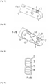
- the Figure 1 represents a key rod 1 of rectangular section, comprising near its end a housing 2 receiving magnets 3, 4.
- the magnets 3, 4 are housed in a non-magnetic capsule 5, made of plastic material for example, which has a annular groove 7 in the interval between magnets 3 and 4 ( Figure 3 ).
- the magnets 3, 4 preferably have the same geometric axis. They are for example cylindrical, but can be of any shape.
- the opposite faces of the magnets 3, 4 are of the same polarity, for example South (S).
- the other faces of the magnets 3, 4, or external faces are also of the same polarity, for example North (N).
- the housing 2 is a cylindrical passage in which the capsule 5 containing the two magnets 3, 4 is inserted.
- a pin 6 is inserted into a passage 8 of axis perpendicular to the axis of the housing 2, and offset with respect to the axis of the housing 2, so that the pin 6 cooperates with the annular groove 7 to maintain the capsule 5 in the rod 1 of the key.
- This maintenance is analyzed as a restraint, and not as a blocking of the capsule 5 in the housing 2 ( Figure 4 ), the whole of the capsule 5 and of the two magnets 3, 4 being endowed with a certain mobility in the housing 2 ( Picture 11 ).
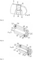
- the Figure 2 represents a round key rod 11, comprising near its end a cylindrical housing 2, with an axis perpendicular to the axis of the key rod 11, capable of receiving a capsule 5 containing two magnets 3, 4 having their faces in look of the same polarity, S for example.
- the capsule 5 is retained in the housing 2 by means of a pin 6 inserted in the passage 8 with an axis perpendicular to the axis of the housing 2, and offset with respect to the axis of the housing 2, the pin 6 cooperating with the annular groove 7 of the capsule 5.
- the axis of the key rod 11 and the axis of the housing 2 define a reference plane for the key.
- the magnets 3, 4 are aligned on the axis of the housing 2.
- This reference plane is a plane of symmetry for the key rod with the exception of the end 9 of the key rod which is polygonal in shape. example of the realization of the Figure 2 .
- the rod 11 of the round key must have a well-defined position in the rotor, at the end of introduction, in order to be able to fulfill its role of driving the rotor. Or the rod 11 round key can be introduced into the rotor with any orientation.
- the rotor 10 carries a fixed pin 12 for the orientation of the rod 11 of the round key ( Figures 9, 10 ).
- the key rod 11 has a guide profile 13, 14 in the form of a wave, arranged symmetrically with respect to the reference plane of the key rod 11.
- This guide profile is also symmetrical with respect to the plane perpendicular to the reference plane of the rod 11 of the key.
- the sliding of the guide profile on the orientation pin ensures the rotation of the key so that at the end of the insertion stroke, the key is in the correct operating position.
- the guide profile being symmetrical with respect to two perpendicular planes, the rotation of the key is a maximum of a quarter turn, and the key is reversible.
- the key has no orientation imposed on the introduction into the rotor of the lock.
- the rotor 10 is housed in a stator or dummy stator 15, to which it is secured in the absence of a key ( Figure 5 ).
- a stator or dummy stator In the vicinity of its inner end, and on an axis perpendicular to the longitudinal axis of the rotor, are arranged, in the upper part a magnet 16 in a first housing 18 and in the lower part a pin 17 in a second housing 19.
- the upper magnet 16 is located in the first housing 18 common to the stator 15 and to the rotor 10. This first housing 18 does not open into the central space of the rotor 10. As a result, the upper magnet 16 rests by gravity on the bottom of the first housing 18.
- the upper magnet 16 fills the part of the first housing 18 located in the rotor 10 and partially the part of the first housing 18 located in the stator 15. In this rest position, the The upper magnet 16 prevents any rotation of the rotor 10 relative to the stator 15.
- the magnet 16 is not subjected to gravity alone, but it is biased by a spring towards the bottom of the housing 18.
- This embodiment variant makes it possible to arrange the housing 18 with an axis with a different orientation from the vertical.
- the lower pin 17 is located in a second housing 19 common to the stator 15 and to the rotor 10.
- This second housing 19 opens into the central space of the rotor 10, in the axis of the first housing 18.
- the second housing 19 there is a conventional stack comprising a spring 20, capped by a cylindrical casing acting as a stator pin 21, and the pin 17 acting as a rotor pin.
- a spring 20 When the key is introduced into the rotor 10, it pushes back the lower pin 17.
- the capsule 5 containing the two magnets 3 and 4 When the key is in the correct position, the capsule 5 containing the two magnets 3 and 4 is opposite the pin 17, the tip of which comes into contact with one of the magnets 3, 4.
- the pin 17 is then entirely in the rotor and the stator pin 21 is then entirely in the stator, and the rotor can turn.
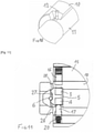
- the capsule 5 containing the two magnets 3 and 4 is provided, not with an annular groove 7, but with a lateral notch 27 of a certain height, providing it with relative movement with respect to the fixed pin 6.
- the capsule 5 is movable in translation along the axis of the housing 2.
- the capsule 5 protrudes from its housing 2, the upper edge of its notch 27 resting on the fixed pin 6. So that the key can be introduced without difficulty into the lock, the capsule 5 has, on either side of its notch 27, oblique faces 28 ensuring that it disappears in the key rod.
- the capsule When the key reaches its final position corresponding to the Picture 11 , the capsule is placed on the lower pin 17 which urges it upwards under the action of its spring 20. To allow the capsule 5 to project above the key rod, the rotor 10 is provided with a recess under the housing 18 of the upper magnet 16.
- the lower pin 17 pushes back the capsule 5 until the lower edge of the notch 27 bears against the fixed pin 6.
- the magnet 3 is then close enough to the upper magnet 16 to push it back, possibly by compressing its spring.
- the capsule 5 performs two functions. On the one hand, it maintains the lower pin 17 entirely in the rotor 10, on the other hand, it maintains the upper magnet 16 entirely in the stator 15. It thus controls two safety points to authorize the rotation of the rotor.
- the rotor 10 comprises a third housing 25 receiving a pin 22 for securing the rotor 10 and the rod key 1 or 11.
- This pin 22 is stressed by a spring 24 and protrudes into the central space of the rotor 10.
- the spring 24, like the spring 20 of the lower pin 17, is capped by a cylindrical casing constituting a pin of stator, which ensures the blocking of the rotor 10 with respect to the stator 15 in the absence of a key.
- the key rod 1 or 11 has two symmetrical notches 23, each of which can receive the pin 22 in a position allowing the rotation of the rotor 10 in the stator 15, and ensuring the joining of the key and the rotor to ensure this rotation ( Figure 6 ).
- the rotor 10 between the third housing 25 of the pin 22 and the first housing 18 of the magnet 16, comprises several housings each receiving a pin, and the key rod comprises as many indentations to receive the tips of the pins.
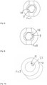
- the rotor 10 has a polygonal housing 26, for example hexagonal, adapted to receive the polygonal end 9 of a round key for example ( Picture 7 ).
- the polygonal housing 26 also receives the polygonal end 9 of the key in its inverted position ( Picture 8 ).
- the two magnets 3 and 4 of the key are mounted on the same geometric axis, with their facing faces of the same polarity (S for example) and their outer faces of the other polarity (N for example).
- the upper magnet 16 has its face facing the key rod of the same polarity as the outer faces of the magnets of the rotor (N for example).
- the upper magnet 16 is not positioned to allow free rotation of the rotor and the cylinder remains locked.
- the upper magnet 16 can be free in its housing 18 and simply subjected to gravity.
- the first housing 18 receives a means for locking the rotor in the absence of a key which, instead of being a magnet such as 16, is a ferromagnetic pin biased by a spring towards the stator.
- a key which, instead of being a magnet such as 16, is a ferromagnetic pin biased by a spring towards the stator.
- the magnets 3, 4 arrive opposite the ferromagnetic pin and attract it by compressing its spring, in a rotor release position.
- the orientation pin 12 of the round key will ensure the correct positioning of the key by bringing the second reference plane into coincidence, defined by the axis of the key rod and the axis of the key magnets, with the first reference plane, of the rotor.
- the introduction of the key into the lock is controlled by the coincidence between the notch 23 of the key rod and the pin 22 securing the rotor to the key.
Landscapes
- Lock And Its Accessories (AREA)
- Permanent Field Magnets Of Synchronous Machinery (AREA)
Claims (17)
- Schloss mit Magnetsteuerung, umfassend einen Zylinder mit Stator und Rotor, die in Abwesenheit eines Schlüssels mit Hilfe von Stiften fest verbunden sind, und einen Schlüssel mit Magneten zum Entsperren des Rotors, wobei der Schlüssel in seinem Schaft (1, 11) eine Einheit von zwei Magneten (3, 4) trägt, die auf einer gleichen Achse senkrecht zur Achse des Schlüsselschafts ausgefluchtet sind, wobei die Seiten gegenüber den zwei Magneten die gleiche Polarität aufweisen, wobei, in einer ersten Aufnahme (18) mit einer senkrechten Achse zur Achse des Rotors (10) der Zylinder ein Mittel zum Versperren des Rotors bei Abwesenheit eines Schlüssels umfasst, das, bei der Einführung des Schlüssels, durch die Magnete (3, 4) des Schlüsselschafts verschiebbar ist, wobei die Achse des Rotors und die Achse der ersten Aufnahme (18) des Zylinders eine erste Referenzebene definieren, die Achse des Schlüsselschafts (1, 11) und die Achse der Magnete (3, 4) des Schlüsselschafts eine zweite Referenzebene definieren und nach der Einführung des Schlüssels in den Zylinder die zwei Referenzebenen übereinstimmen, wobei der Schlüsselschaft rund ist und die Übereinstimmung der Referenzebenen des Zylinders und des Schlüsselschafts mit Hilfe eines festen Stifts (12) des Rotors sichergestellt ist, dadurch gekennzeichnet, dass der Schlüsselschaft ein Führungsprofil (13, 14) in Form einer Welle umfasst, um, im Laufe des Fortschreitens des Schlüsselschafts im Zylinder durch Gleiten des Führungsprofils auf dem festen Stift (12) des Rotors die Übereinstimmung der Referenzebenen des Zylinders und des Schlüsselschafts herbeizuführen.
- Schloss nach Anspruch 1, dadurch gekennzeichnet, dass der Schlüsselschaft mindestens eine Aussparung (23) umfasst, um mindestens einen Stift (22) des Zylinders aufzunehmen, der, nach der Einführung des Schlüsselschafts in den Zylinder die feste Verbindung des Schlüsselschafts und des Rotors sicherstellt, um die Betätigung des Rotors mit Hilfe des Schlüssels zu ermöglichen.
- Schloss nach einem der Ansprüche 1 und 2, dadurch gekennzeichnet, dass der Schlüsselschaft eine Aufnahme (2) aufweist, in die eine Kapsel (5) eingeführt ist, die die Magnete (3, 4) enthält.
- Schloss nach einem der Ansprüche 1 bis 3, dadurch gekennzeichnet, dass in der Achse der ersten Aufnahme (18) der Zylinder eine zweite Aufnahme (19) umfasst, umfassend einen Stift (17), der von einer Feder (20) beansprucht wird und die Freisetzung des Rotors (10) sicherstellt, wenn er sich gegenüber der Kapsel (5) befindet, die die Magnete (3, 4) enthält.
- Schloss nach Anspruch 3, dadurch gekennzeichnet, dass die Kapsel (5) eine ringförmige Auskehlung (7) aufweist, die einen festen Stift (6) aufnimmt.
- Schloss nach Anspruch 3, dadurch gekennzeichnet, dass die Kapsel (5) eine seitliche Aussparung (27) aufweist, die eine relative Verschiebung mit Bezug auf einen festen Stift (6) sicherstellt.
- Schloss nach Anspruch 6, dadurch gekennzeichnet, dass die Kapsel (5) auf beiden Seiten ihrer Aussparung (27) schräge Teile (28) aufweist.
- Schloss nach Anspruch 6, dadurch gekennzeichnet, dass mit dem unteren Rand ihrer Aussparung (27) in Auflage auf dem festen Stift (6) die Kapsel (5) die Position des unteren Stifts (17) im Rotor (10) und die Position des oberen Magneten (16) im Stator (15) sicherstellt und so die Drehung des Rotors (10) ermöglicht.
- Schloss nach einem der Ansprüche 1 bis 8, dadurch gekennzeichnet, dass der Rotor an seinem Ende eine polygonale Aufnahme (26) aufweist und der Schlüsselschaft (11) ein polygonales Ende (9) aufweist, das ausgelegt ist, um in die polygonale Aufnahme (26) des Rotors eingeführt zu werden, unabhängig von der Richtung der Einführung des Schlüsselschafts in den Zylinder.
- Schloss nach Anspruch 1, dadurch gekennzeichnet, dass das Mittel zum Versperren des Rotors bei Abwesenheit eines Schlüssels ein Magnet (16) ist, dessen Seite gegenüber der Achse des Rotors die gleiche Polarität wie die äußeren Seiten der Magneten (3, 4) des Schlüsselschafts aufweisen.
- Schloss nach Anspruch 10, dadurch gekennzeichnet, dass die erste Aufnahme (18) eine vertikale Achse aufweist und der Magnet (16) in der Aufnahme (18) nur der Schwerkraft ausgesetzt ist und von den Magneten (3, 4) des Schlüsselschafts zurückgestoßen wird.
- Schloss nach Anspruch 10, dadurch gekennzeichnet, dass die erste Aufnahme (18) eine Achse mit einer verschiedenen Ausrichtung als die Vertikale aufweist und der Magnet (16) in der Aufnahme (18) von einer Feder beansprucht wird.
- Schloss nach Anspruch 1, dadurch gekennzeichnet, dass das Mittel zum Versperren des Rotors bei Abwesenheit eines Schlüssels ein ferromagnetischer Stift ist, der von einer Feder beansprucht und gegen die Wirkung der Feder von den Magneten (3, 4) des Schlüsselschafts angezogen wird.
- Schlüssel für Schloss mit Magnetsteuerung nach einem der Ansprüche 1 bis 13, umfassend einen Schlüsselschaft (1, 11) mit einer Achse und einer Referenzebene, so dass er eine Aufnahme (2) mit einer Achse umfasst, die in der Referenzebene enthalten und senkrecht zur Achse des Schlüsselschafts (1, 11) ist, dadurch gekennzeichnet, dass in der Aufnahme (2) eine Kapsel (5) zwei Magnete (3, 4) enthält, die auf der Achse der Aufnahme (2) ausgefluchtet sind, wobei die Seiten gegenüber den zwei Magneten (3, 4) die gleiche Polarität aufweisen.
- Schlüssel nach Anspruch 14, dadurch gekennzeichnet, dass er reversibel ist.
- Schlüssel nach Anspruch 14, dadurch gekennzeichnet, dass sein Schaft (1) flach ist.
- Schlüssel nach Anspruch 14, dadurch gekennzeichnet, dass sein Schaft (11) rund ist und ein Führungsprofil (13, 14) aufweist, das symmetrisch mit Bezug auf seine Referenzebene ist.
Applications Claiming Priority (1)
| Application Number | Priority Date | Filing Date | Title |
|---|---|---|---|
| FR1901694A FR3092856B1 (fr) | 2019-02-20 | 2019-02-20 | Serrure à contrôle par aimants |
Publications (2)
| Publication Number | Publication Date |
|---|---|
| EP3699376A1 EP3699376A1 (de) | 2020-08-26 |
| EP3699376B1 true EP3699376B1 (de) | 2022-02-09 |
Family
ID=68138164
Family Applications (1)
| Application Number | Title | Priority Date | Filing Date |
|---|---|---|---|
| EP20154100.0A Active EP3699376B1 (de) | 2019-02-20 | 2020-01-28 | Schloss mit magnetsteuerung |
Country Status (4)
| Country | Link |
|---|---|
| EP (1) | EP3699376B1 (de) |
| DK (1) | DK3699376T3 (de) |
| ES (1) | ES2910431T3 (de) |
| FR (1) | FR3092856B1 (de) |
Family Cites Families (7)
| Publication number | Priority date | Publication date | Assignee | Title |
|---|---|---|---|---|
| JPS5238479B2 (de) * | 1973-11-24 | 1977-09-29 | ||
| EP0571311A1 (de) | 1992-04-23 | 1993-11-24 | Metalurgica Cerrajera De Mondragon, S.A. | Zylinderschloss mit magnetischen Stiftzuhaltungen |
| KR20020050057A (ko) * | 2000-12-20 | 2002-06-26 | 김태동 | 이중 자물쇠 장치 |
| EP1482108B1 (de) | 2003-05-28 | 2010-06-02 | ISEO Deutschland GmbH | Schlüssel-Schlosskombination mit einem kopiergeschützen Profil-Flachschlüssel |
| CN201972462U (zh) * | 2010-12-02 | 2011-09-14 | 韩军 | 一种磁性锁及其开启钥匙 |
| DE102011014797B3 (de) | 2011-02-25 | 2012-03-01 | Assa Abloy Sicherheitstechnik Gmbh | Schließzylinder mit zugehörigem Schlüssel |
| DE102014004190B4 (de) * | 2014-03-18 | 2016-11-10 | Assa Abloy Sicherheitstechnik Gmbh | Schließzylinder-Schlüssel-System |
-
2019
- 2019-02-20 FR FR1901694A patent/FR3092856B1/fr not_active Expired - Fee Related
-
2020
- 2020-01-28 EP EP20154100.0A patent/EP3699376B1/de active Active
- 2020-01-28 ES ES20154100T patent/ES2910431T3/es active Active
- 2020-01-28 DK DK20154100.0T patent/DK3699376T3/da active
Also Published As
| Publication number | Publication date |
|---|---|
| FR3092856B1 (fr) | 2021-03-05 |
| ES2910431T3 (es) | 2022-05-12 |
| EP3699376A1 (de) | 2020-08-26 |
| DK3699376T3 (da) | 2022-05-02 |
| FR3092856A1 (fr) | 2020-08-21 |
Similar Documents
| Publication | Publication Date | Title |
|---|---|---|
| EP4049895B1 (de) | Magnetische befestigungsvorrichtung | |
| FR3046032A1 (fr) | Bagage muni d'un dispositif de verrouillage de fermeture a glissiere | |
| EP0076711B1 (de) | Automatisch schliessendes Schloss | |
| EP1601848B1 (de) | Magnetisch gesteuerte sperrvorrichtung | |
| EP3699376B1 (de) | Schloss mit magnetsteuerung | |
| EP0359885A1 (de) | Schlüssel mit Schiebeelement, Sicherheitszylinder, und Schloss mit solchen Zylindern | |
| EP3101206B1 (de) | Magnetisches sicherheitsschloss | |
| EP1554916B1 (de) | Einrichtung zur verriegelten anbringung einer für rackmontage ausgelegten vorrichtung | |
| EP2960406B1 (de) | Vorrichtung zum öffnen und schliessen eines artikels, insbesondere eines lederwaren-artikels, und artikel, der eine solche vorrichtung umfasst | |
| EP0305245A1 (de) | Verriegelung eines Deckels auf einem Rahmen | |
| FR3065684A1 (fr) | Ensemble de garnissage comprenant une piece deployable | |
| FR2955137A1 (fr) | Dispositif formant charniere magnetique | |
| CA3140657C (fr) | Systeme de prehension d'une cle | |
| FR2585757A1 (fr) | Dispositif de verrouillage d'un couvercle, d'une trappe ou d'un element analogue | |
| FR2697566A1 (fr) | Serrure à pêne basculant. | |
| FR3036421A1 (fr) | Dispositif de verrouillage d'un doigt de retenue relie a un couvercle | |
| FR2631202A1 (fr) | Dispositif de manoeuvre du mecanisme de clipsage des appareils electriques modulaires | |
| FR3165458A1 (fr) | Dispositif de verrouillage avec déverrouillage magnétique et ensemble de verrouillage associé | |
| EP4130413B1 (de) | Verlängerungsvorrichtung für eine tür-/fensterzarge und detektionssystem | |
| EP3882418B1 (de) | Modularer zylinder für sicherheitsschloss | |
| FR2917794A1 (fr) | Dispositif de fixation inviolable d'une piece dans une decoupe prevue sur une structure. | |
| FR2486497A1 (fr) | Systeme de fermeture pour boite | |
| FR2701285A1 (fr) | Système de fermeture de porte. | |
| FR3165459A1 (fr) | Ensemble de verrouillage magnétique | |
| WO2025262027A1 (fr) | Dispositif de déclipsage d'un ouvrant par rotation contre un dormant |
Legal Events
| Date | Code | Title | Description |
|---|---|---|---|
| PUAI | Public reference made under article 153(3) epc to a published international application that has entered the european phase |
Free format text: ORIGINAL CODE: 0009012 |
|
| STAA | Information on the status of an ep patent application or granted ep patent |
Free format text: STATUS: THE APPLICATION HAS BEEN PUBLISHED |
|
| AK | Designated contracting states |
Kind code of ref document: A1 Designated state(s): AL AT BE BG CH CY CZ DE DK EE ES FI FR GB GR HR HU IE IS IT LI LT LU LV MC MK MT NL NO PL PT RO RS SE SI SK SM TR |
|
| AX | Request for extension of the european patent |
Extension state: BA ME |
|
| STAA | Information on the status of an ep patent application or granted ep patent |
Free format text: STATUS: REQUEST FOR EXAMINATION WAS MADE |
|
| 17P | Request for examination filed |
Effective date: 20201203 |
|
| RBV | Designated contracting states (corrected) |
Designated state(s): AL AT BE BG CH CY CZ DE DK EE ES FI FR GB GR HR HU IE IS IT LI LT LU LV MC MK MT NL NO PL PT RO RS SE SI SK SM TR |
|
| RIN1 | Information on inventor provided before grant (corrected) |
Inventor name: JULIEN, HERVE Inventor name: GOSSIAUX, ALEXANDRE Inventor name: ROBIN, HERVE |
|
| GRAP | Despatch of communication of intention to grant a patent |
Free format text: ORIGINAL CODE: EPIDOSNIGR1 |
|
| STAA | Information on the status of an ep patent application or granted ep patent |
Free format text: STATUS: GRANT OF PATENT IS INTENDED |
|
| INTG | Intention to grant announced |
Effective date: 20211105 |
|
| GRAS | Grant fee paid |
Free format text: ORIGINAL CODE: EPIDOSNIGR3 |
|
| GRAA | (expected) grant |
Free format text: ORIGINAL CODE: 0009210 |
|
| STAA | Information on the status of an ep patent application or granted ep patent |
Free format text: STATUS: THE PATENT HAS BEEN GRANTED |
|
| AK | Designated contracting states |
Kind code of ref document: B1 Designated state(s): AL AT BE BG CH CY CZ DE DK EE ES FI FR GB GR HR HU IE IS IT LI LT LU LV MC MK MT NL NO PL PT RO RS SE SI SK SM TR |
|
| REG | Reference to a national code |
Ref country code: GB Ref legal event code: FG4D Free format text: NOT ENGLISH |
|
| REG | Reference to a national code |
Ref country code: CH Ref legal event code: EP Ref country code: AT Ref legal event code: REF Ref document number: 1467607 Country of ref document: AT Kind code of ref document: T Effective date: 20220215 |
|
| REG | Reference to a national code |
Ref country code: IE Ref legal event code: FG4D Free format text: LANGUAGE OF EP DOCUMENT: FRENCH |
|
| REG | Reference to a national code |
Ref country code: DE Ref legal event code: R096 Ref document number: 602020001767 Country of ref document: DE |
|
| RAP4 | Party data changed (patent owner data changed or rights of a patent transferred) |
Owner name: ASSA ABLOY FRANCE SAS |
|
| REG | Reference to a national code |
Ref country code: DK Ref legal event code: T3 Effective date: 20220428 Ref country code: NO Ref legal event code: T2 Effective date: 20220209 |
|
| REG | Reference to a national code |
Ref country code: FI Ref legal event code: FGE |
|
| REG | Reference to a national code |
Ref country code: ES Ref legal event code: FG2A Ref document number: 2910431 Country of ref document: ES Kind code of ref document: T3 Effective date: 20220512 |
|
| REG | Reference to a national code |
Ref country code: DE Ref legal event code: R081 Ref document number: 602020001767 Country of ref document: DE Owner name: ASSA ABLOY FRANCE SAS, FR Free format text: FORMER OWNER: ASSA ABLOY FRANCE SAS, CLAMART, FR |
|
| REG | Reference to a national code |
Ref country code: SE Ref legal event code: TRGR |
|
| REG | Reference to a national code |
Ref country code: LT Ref legal event code: MG9D |
|
| REG | Reference to a national code |
Ref country code: NL Ref legal event code: MP Effective date: 20220209 |
|
| REG | Reference to a national code |
Ref country code: AT Ref legal event code: MK05 Ref document number: 1467607 Country of ref document: AT Kind code of ref document: T Effective date: 20220209 |
|
| REG | Reference to a national code |
Ref country code: SK Ref legal event code: T3 Ref document number: E 39719 Country of ref document: SK |
|
| PG25 | Lapsed in a contracting state [announced via postgrant information from national office to epo] |
Ref country code: RS Free format text: LAPSE BECAUSE OF FAILURE TO SUBMIT A TRANSLATION OF THE DESCRIPTION OR TO PAY THE FEE WITHIN THE PRESCRIBED TIME-LIMIT Effective date: 20220209 Ref country code: PT Free format text: LAPSE BECAUSE OF FAILURE TO SUBMIT A TRANSLATION OF THE DESCRIPTION OR TO PAY THE FEE WITHIN THE PRESCRIBED TIME-LIMIT Effective date: 20220609 Ref country code: NL Free format text: LAPSE BECAUSE OF FAILURE TO SUBMIT A TRANSLATION OF THE DESCRIPTION OR TO PAY THE FEE WITHIN THE PRESCRIBED TIME-LIMIT Effective date: 20220209 Ref country code: LT Free format text: LAPSE BECAUSE OF FAILURE TO SUBMIT A TRANSLATION OF THE DESCRIPTION OR TO PAY THE FEE WITHIN THE PRESCRIBED TIME-LIMIT Effective date: 20220209 Ref country code: HR Free format text: LAPSE BECAUSE OF FAILURE TO SUBMIT A TRANSLATION OF THE DESCRIPTION OR TO PAY THE FEE WITHIN THE PRESCRIBED TIME-LIMIT Effective date: 20220209 Ref country code: BG Free format text: LAPSE BECAUSE OF FAILURE TO SUBMIT A TRANSLATION OF THE DESCRIPTION OR TO PAY THE FEE WITHIN THE PRESCRIBED TIME-LIMIT Effective date: 20220509 |
|
| PG25 | Lapsed in a contracting state [announced via postgrant information from national office to epo] |
Ref country code: PL Free format text: LAPSE BECAUSE OF FAILURE TO SUBMIT A TRANSLATION OF THE DESCRIPTION OR TO PAY THE FEE WITHIN THE PRESCRIBED TIME-LIMIT Effective date: 20220209 Ref country code: LV Free format text: LAPSE BECAUSE OF FAILURE TO SUBMIT A TRANSLATION OF THE DESCRIPTION OR TO PAY THE FEE WITHIN THE PRESCRIBED TIME-LIMIT Effective date: 20220209 Ref country code: GR Free format text: LAPSE BECAUSE OF FAILURE TO SUBMIT A TRANSLATION OF THE DESCRIPTION OR TO PAY THE FEE WITHIN THE PRESCRIBED TIME-LIMIT Effective date: 20220510 Ref country code: AT Free format text: LAPSE BECAUSE OF FAILURE TO SUBMIT A TRANSLATION OF THE DESCRIPTION OR TO PAY THE FEE WITHIN THE PRESCRIBED TIME-LIMIT Effective date: 20220209 |
|
| PG25 | Lapsed in a contracting state [announced via postgrant information from national office to epo] |
Ref country code: IS Free format text: LAPSE BECAUSE OF FAILURE TO SUBMIT A TRANSLATION OF THE DESCRIPTION OR TO PAY THE FEE WITHIN THE PRESCRIBED TIME-LIMIT Effective date: 20220609 |
|
| PG25 | Lapsed in a contracting state [announced via postgrant information from national office to epo] |
Ref country code: SM Free format text: LAPSE BECAUSE OF FAILURE TO SUBMIT A TRANSLATION OF THE DESCRIPTION OR TO PAY THE FEE WITHIN THE PRESCRIBED TIME-LIMIT Effective date: 20220209 Ref country code: RO Free format text: LAPSE BECAUSE OF FAILURE TO SUBMIT A TRANSLATION OF THE DESCRIPTION OR TO PAY THE FEE WITHIN THE PRESCRIBED TIME-LIMIT Effective date: 20220209 Ref country code: EE Free format text: LAPSE BECAUSE OF FAILURE TO SUBMIT A TRANSLATION OF THE DESCRIPTION OR TO PAY THE FEE WITHIN THE PRESCRIBED TIME-LIMIT Effective date: 20220209 |
|
| REG | Reference to a national code |
Ref country code: DE Ref legal event code: R097 Ref document number: 602020001767 Country of ref document: DE |
|
| PG25 | Lapsed in a contracting state [announced via postgrant information from national office to epo] |
Ref country code: AL Free format text: LAPSE BECAUSE OF FAILURE TO SUBMIT A TRANSLATION OF THE DESCRIPTION OR TO PAY THE FEE WITHIN THE PRESCRIBED TIME-LIMIT Effective date: 20220209 |
|
| PLBE | No opposition filed within time limit |
Free format text: ORIGINAL CODE: 0009261 |
|
| STAA | Information on the status of an ep patent application or granted ep patent |
Free format text: STATUS: NO OPPOSITION FILED WITHIN TIME LIMIT |
|
| 26N | No opposition filed |
Effective date: 20221110 |
|
| PG25 | Lapsed in a contracting state [announced via postgrant information from national office to epo] |
Ref country code: SI Free format text: LAPSE BECAUSE OF FAILURE TO SUBMIT A TRANSLATION OF THE DESCRIPTION OR TO PAY THE FEE WITHIN THE PRESCRIBED TIME-LIMIT Effective date: 20220209 |
|
| PG25 | Lapsed in a contracting state [announced via postgrant information from national office to epo] |
Ref country code: LU Free format text: LAPSE BECAUSE OF NON-PAYMENT OF DUE FEES Effective date: 20230128 |
|
| PG25 | Lapsed in a contracting state [announced via postgrant information from national office to epo] |
Ref country code: IE Free format text: LAPSE BECAUSE OF NON-PAYMENT OF DUE FEES Effective date: 20230128 |
|
| PG25 | Lapsed in a contracting state [announced via postgrant information from national office to epo] |
Ref country code: MC Free format text: LAPSE BECAUSE OF FAILURE TO SUBMIT A TRANSLATION OF THE DESCRIPTION OR TO PAY THE FEE WITHIN THE PRESCRIBED TIME-LIMIT Effective date: 20220209 |
|
| PG25 | Lapsed in a contracting state [announced via postgrant information from national office to epo] |
Ref country code: MC Free format text: LAPSE BECAUSE OF FAILURE TO SUBMIT A TRANSLATION OF THE DESCRIPTION OR TO PAY THE FEE WITHIN THE PRESCRIBED TIME-LIMIT Effective date: 20220209 |
|
| PG25 | Lapsed in a contracting state [announced via postgrant information from national office to epo] |
Ref country code: CY Free format text: LAPSE BECAUSE OF FAILURE TO SUBMIT A TRANSLATION OF THE DESCRIPTION OR TO PAY THE FEE WITHIN THE PRESCRIBED TIME-LIMIT; INVALID AB INITIO Effective date: 20200128 |
|
| PG25 | Lapsed in a contracting state [announced via postgrant information from national office to epo] |
Ref country code: HU Free format text: LAPSE BECAUSE OF FAILURE TO SUBMIT A TRANSLATION OF THE DESCRIPTION OR TO PAY THE FEE WITHIN THE PRESCRIBED TIME-LIMIT; INVALID AB INITIO Effective date: 20200128 |
|
| PGFP | Annual fee paid to national office [announced via postgrant information from national office to epo] |
Ref country code: GB Payment date: 20251211 Year of fee payment: 7 |
|
| PGFP | Annual fee paid to national office [announced via postgrant information from national office to epo] |
Ref country code: FI Payment date: 20251230 Year of fee payment: 7 |
|
| PGFP | Annual fee paid to national office [announced via postgrant information from national office to epo] |
Ref country code: FR Payment date: 20251222 Year of fee payment: 7 |
|
| PGFP | Annual fee paid to national office [announced via postgrant information from national office to epo] |
Ref country code: SE Payment date: 20251210 Year of fee payment: 7 |
|
| PGFP | Annual fee paid to national office [announced via postgrant information from national office to epo] |
Ref country code: CZ Payment date: 20251229 Year of fee payment: 7 |
|
| PGFP | Annual fee paid to national office [announced via postgrant information from national office to epo] |
Ref country code: SK Payment date: 20251212 Year of fee payment: 7 |
|
| REG | Reference to a national code |
Ref country code: CH Ref legal event code: U11 Free format text: ST27 STATUS EVENT CODE: U-0-0-U10-U11 (AS PROVIDED BY THE NATIONAL OFFICE) Effective date: 20260201 |
|
| PGFP | Annual fee paid to national office [announced via postgrant information from national office to epo] |
Ref country code: ES Payment date: 20260209 Year of fee payment: 7 |
|
| PGFP | Annual fee paid to national office [announced via postgrant information from national office to epo] |
Ref country code: NO Payment date: 20260109 Year of fee payment: 7 Ref country code: DK Payment date: 20260113 Year of fee payment: 7 Ref country code: DE Payment date: 20251210 Year of fee payment: 7 |
|
| PGFP | Annual fee paid to national office [announced via postgrant information from national office to epo] |
Ref country code: BE Payment date: 20260106 Year of fee payment: 7 Ref country code: IT Payment date: 20251219 Year of fee payment: 7 |
|
| PGFP | Annual fee paid to national office [announced via postgrant information from national office to epo] |
Ref country code: TR Payment date: 20260123 Year of fee payment: 7 |
|
| PGFP | Annual fee paid to national office [announced via postgrant information from national office to epo] |
Ref country code: CH Payment date: 20260201 Year of fee payment: 7 |