EP3699391A1 - Erdbohrvorrichtung und verfahren zum bohren in erdreich - Google Patents
Erdbohrvorrichtung und verfahren zum bohren in erdreich Download PDFInfo
- Publication number
- EP3699391A1 EP3699391A1 EP20158158.4A EP20158158A EP3699391A1 EP 3699391 A1 EP3699391 A1 EP 3699391A1 EP 20158158 A EP20158158 A EP 20158158A EP 3699391 A1 EP3699391 A1 EP 3699391A1
- Authority
- EP
- European Patent Office
- Prior art keywords
- receptacle
- slide
- carriage
- drilling
- drill rod
- Prior art date
- Legal status (The legal status is an assumption and is not a legal conclusion. Google has not performed a legal analysis and makes no representation as to the accuracy of the status listed.)
- Granted
Links
Images

Classifications
-
- E—FIXED CONSTRUCTIONS
- E21—EARTH OR ROCK DRILLING; MINING
- E21B—EARTH OR ROCK DRILLING; OBTAINING OIL, GAS, WATER, SOLUBLE OR MELTABLE MATERIALS OR A SLURRY OF MINERALS FROM WELLS
- E21B17/00—Drilling rods or pipes; Flexible drill strings; Kellies; Drill collars; Sucker rods; Cables; Casings; Tubings
- E21B17/02—Couplings; joints
- E21B17/021—Devices for subsurface connecting or disconnecting by rotation
-
- E—FIXED CONSTRUCTIONS
- E21—EARTH OR ROCK DRILLING; MINING
- E21B—EARTH OR ROCK DRILLING; OBTAINING OIL, GAS, WATER, SOLUBLE OR MELTABLE MATERIALS OR A SLURRY OF MINERALS FROM WELLS
- E21B7/00—Special methods or apparatus for drilling
-
- E—FIXED CONSTRUCTIONS
- E21—EARTH OR ROCK DRILLING; MINING
- E21B—EARTH OR ROCK DRILLING; OBTAINING OIL, GAS, WATER, SOLUBLE OR MELTABLE MATERIALS OR A SLURRY OF MINERALS FROM WELLS
- E21B17/00—Drilling rods or pipes; Flexible drill strings; Kellies; Drill collars; Sucker rods; Cables; Casings; Tubings
- E21B17/02—Couplings; joints
- E21B17/04—Couplings; joints between rod or the like and bit or between rod and rod or the like
- E21B17/042—Threaded
-
- E—FIXED CONSTRUCTIONS
- E21—EARTH OR ROCK DRILLING; MINING
- E21B—EARTH OR ROCK DRILLING; OBTAINING OIL, GAS, WATER, SOLUBLE OR MELTABLE MATERIALS OR A SLURRY OF MINERALS FROM WELLS
- E21B7/00—Special methods or apparatus for drilling
- E21B7/20—Driving or forcing casings or pipes into boreholes, e.g. sinking; Simultaneously drilling and casing boreholes
-
- E—FIXED CONSTRUCTIONS
- E21—EARTH OR ROCK DRILLING; MINING
- E21B—EARTH OR ROCK DRILLING; OBTAINING OIL, GAS, WATER, SOLUBLE OR MELTABLE MATERIALS OR A SLURRY OF MINERALS FROM WELLS
- E21B7/00—Special methods or apparatus for drilling
- E21B7/28—Enlarging drilled holes, e.g. by counterboring
- E21B7/30—Enlarging drilled holes, e.g. by counterboring without earth removal
Definitions
- the invention relates to an earth drilling device for drilling in the earth by means of a drill rod and to a method for drilling in the earth by means of a drill rod.
- Earth drilling devices in particular horizontal drilling devices, are used to drill earth holes in the ground using trenchless construction, for example for supply and disposal lines, or to replace existing lines without trenches.
- a drill rod is usually used which has drill rod sections and in which the drill rod sections can be connected to one another.
- EP 0 886 034 B1 known to use a carriage reciprocable in a frame for advancing and / or pulling a drill rod.
- the carriage has a receptacle for a drill rod section, so that the drill rod section can be moved in the direction of a feed axis for creating the earth bore in the receptacle.
- the drive acting on the drill rod section can act rotationally and / or translationally on the drill rod section in the receptacle.
- the mounting of the (drilled) drill string that has already been introduced into the ground is usually released and the slide is moved against the feed direction and a new drill string section is to be connected to the drill string that has already been drilled. introduced into the receptacle of the slide. The slide is then moved in the feed direction and the drill rod section is connected, in particular screwed, to the drill rod that has already been drilled.
- threads are arranged at the ends of the drill rod sections, which are used to screw the drill rod sections together.
- the invention was therefore based on the object of creating an improved earth drilling device and a method for drilling in the ground, with which an improved drilling of an earth bore is possible, in particular a faster introduction of the earth drilling is possible.
- the core idea of the invention is to make a receptacle for a rod section, which is to be screw-connected to the drill rod that has already been drilled, so that it can be moved relative to the slide. Due to the displaceability of the receptacle relative to the slide, in particular in the direction of the drill rod or away from it, it is possible to compensate for a change in the position of the receptacle caused by the screwing in relation to the rod section to be screwed or loosened. It should also be taken into account that the position of the rod section to be added also changes when it is connected to the drill rod and the receptacle.
- the slide itself can - although the recording Moved to compensate for the change in length caused by the screwing - stand still and, in particular, remain in direct frictional connection with the drive driving the slide In this way, the drilling process can be continued immediately after the screwing process. Careful approach of the slide after the extension of the drill rod by means of a rod section to be screwed to the drilled drill rod can be reduced or eliminated entirely.
- the invention provides an earth boring device for drilling in the ground by means of a drill rod, the earth boring device having a drilling carriage and a carriage which can be moved translationally on the drilling carriage.
- a receptacle is arranged on the slide.
- the receptacle is provided for screwing connection of a rod section to the drill rod or for screwing loosening of a rod section from the drill rod.
- the receptacle can be moved relatively translationally to the slide, in particular in the direction of the drill rod or away from it, to compensate for a change in the position of the receptacle caused by the screwing.
- earth boring device in the sense of the description includes any device that moves in particular a drill pipe having drill rods in an existing or to be created channel in the ground in order to create or widen a bore, in particular a horizontal bore, or around lines or other long bodies to move into the ground.
- An earth drilling device can comprise a drive device which drives a drill pipe in a pulling and / or pushing or pushing manner. It can additionally or alternatively be provided that the drive device drives the drill rod in a rotational manner.
- An earth boring device can be a device which drives a drill pipe and which, in particular, works by displacing the earth.
- horizontal drilling in the sense of the present description includes in particular any type of existing or to be created channels in a body, preferably at least partially horizontally running channels, in particular earth channels including earth bores, rock bores or earth lines as well as underground or surface pipes and water channels, which can be produced or pulled in using a suitable earth boring device.
- drill pipe in the sense of the description includes any means that can be placed in the ground in order to drill a hole in the ground.
- the drill rod can in particular have a rod, a chain and / or a rope.
- the term “drill rods” does not exclusively include rigid drill rods having individual rod sections connected directly or indirectly to one another, but in particular all force transmission elements that can be used in an earth boring device.
- the drill rod in particular at a front end, can comprise a drill head and / or an optionally present drill head tip or an area adjacent to the drill head, which is designed or has this as a drilling tool.
- the term "drill carriage” includes a, in particular mobile, frame on which a slide can be provided for moving the drill rod, which slide can be moved back and forth in the direction of the drill rod axis in order to move the drill rod in the ground by pushing or pulling.
- the slide can be moved relative to the drilling carriage using a linear drive.
- the drill carriage can also have one or more clamping devices by means of which the drill rod or a rod section to be attached can be fixed. It can be provided that a clamping device is provided on the drill carriage, by means of which the free end of the drill rod (the end protruding from the ground) can be fixed in order to enable a new rod section to be connected to the drill rod that has already been drilled.
- a receptacle is provided on the slide that can accommodate a rod section that is to be newly added or detached, in particular at the end, in such a way that the receptacle fixes the rod section non-positively and / or positively in order to be able to drive the rod section, in particular rotating around its longitudinal axis .
- the receptacle can be configured, for example, in such a way that the end of the receptacle engages with a rod section to be loosened or screwed and a form fit is generated. If the holder is rotated, the rod section picked up by the holder can be rotated.
- position of the receptacle or a rod section includes in the sense of the description in particular the position of the receptacle or the rod section, as specified by the method along the drilling carriage, wherein the position can change in particular that the in the The rod section located in the receptacle is screwed to the drill rod and the receptacle or is unscrewed from it can be.
- a change in position is essentially a translational movement of the receptacle along the drill rod axis. The change in the position of the receptacle in relation to the rod section to be screwed or loosened corresponds to the change in the position of the receptacle in relation to the drilled drill rod.
- a carrier carrying the receptacle is arranged displaceably on the slide and can be fixed on the slide.
- the carriage can thus have a substructure with respect to which the carrier can be displaced.
- an optional fixation with the slide / substructure or an optional fixation with respect to the slide / substructure can be achieved. If the carrier is fixed in relation to the slide / substructure, the slide / substructure and the carrier can move together. If the fixation between the carrier and the carriage is optionally released, a relative movement between the carrier and the carriage can take place with the result that the receptacle carried by the carrier can move relative to the carriage. While the slide remains in the frictional connection with the drive that drives the slide, the holder can be moved with the carrier.
- the direction in which the carrier can be displaced with respect to the slide is oriented essentially in the direction of the drill rod or offset parallel to it.
- the carrier can be fixed on the slide by means of a bolt which, in particular, can be actuated hydraulically.
- a particularly simple design can be achieved in this way.
- a bolt on the carrier or carriage / substructure can move into a corresponding recess in the other of the two elements of the carrier and carriage.
- a positive fit can be formed between the carrier and the slide such that this positive fit acts transversely to the direction in which the carrier is relatively displaceable with respect to the slide / substructure.
- the form fit is preferably designed in a direction which is particularly preferred at an angle with the direction of displacement between the carrier and the slide / substructure of more than 50 °, in particular more than 60 °, in particular more than 70 °, in particular more than 80 ° 90 °.
- a frictional connection can also be provided.
- a sensor for detecting the end of the screwing process there is a sensor for detecting the end of the screwing process, the signal of which can be received by a control device in order to fix the receptacle to the slide.
- the introduction of the auger can be controlled automatically as far as possible.
- a signal that the sensor makes available to the control device can be used to indicate to the control device that a fixation is being carried out again can.
- the carrier can be fixed again on the slide / substructure.
- control device in the sense of the description comprises an embodiment of a control by means of which a directional influencing of the earth drilling device during operation, i.e. during the implementation or for starting or stopping an earth borehole.
- the control device can in particular be designed electrically or electronically.
- Inputs entered by an operator and / or parameters for carrying out the drilling can be used by the control device - optionally converted and / or processed into electrical signals - as inputs for the operation of the earth drilling device.
- the earth boring device can thus be operated or controlled by means of an input, in particular a parameter, which may have been converted into an electrical signal.
- a “parameter” in the sense of the description is understood to be an input with which a directional influencing of the operation of the earth drilling device is possible.
- the parameter can be transmitted as an input signal to the control device, by means of which the control device controls the operation of the earth boring device.
- a parameter can, for example, cause drilling to be started with the auger device or to stop a drilling carried out with the auger device.
- the senor can be a limit switch, a proximity switch, a position switch or the like.
- the receptacle is fixed on the carriage / substructure automatically or semi-automatically by means of a signal from a sensor.
- the sensor can detect the position of the receptacle and / or an optionally present carrier.
- a pressure sensor can be provided which detects an increase in pressure in the hydraulic drive of the rotation for recording when the threads are closed or moved to the stop.
- an input device which supplies a signal that can be received by a control device in order to fix the drive means to the carriage / substructure. This makes it possible for an operator to manually fix the receptacle to the carriage / substructure. An operator monitors the process of adding or removing the last rod section on the drill rod.
- the term “input device” in the sense of the description includes any electrical or electronic device that is suitable for converting an input from an operator into an electrical signal.
- the electrical signal can be processed without further processing to be transmitted to the control device with the interposition of a conditioning of the signal, in particular processing in one or more circuits, for example in an amplifier, in order to serve as an input or as an input signal of the control device.
- the input device can be understood as an interface between an operator and the control device.
- the input device can in particular be a keyboard, a joystick, a microphone, a switch, a push button or the like.
- the invention also provides a method for drilling in the ground by means of a drill string, a translationally movable carriage being used to pull and / or push the drill string.
- a receptacle is arranged on the slide, with which a rod section is screwed to or unscrewed from a drill rod. The receptacle is moved relatively translationally to the slide in order to compensate for a change in the position of the receptacle caused by the screwing.
- the invention is described in terms of two aspects relating to an earth boring apparatus and a method of drilling in the earth.
- the statements on the individual aspects complement one another, so that the statements for the earth boring device are also to be understood as statements of the description for the method and vice versa.
- the description of the earth boring device also discloses actions in the sense of the method or method steps relating to the method and vice versa.
- a numerical value in particular an angle specification, not only includes the actual numerical value, but also - in order to take into account manufacturing tolerances in particular - a range around the specific numerical value, which is +/- 15%, preferably +/- 10% , can be of the specified numerical value.
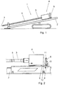
- Fig. 1 shows, in a schematic representation from the side, an earth drilling device 1 which works to displace soil.
- a drill rod which has rod sections 5, can be introduced into the ground translationally and rotationally.
- a slide 4 can be moved back and forth on a drilling carriage 2.
- the drill carriage 2 defines a drill rod axis 7 with the slide 4 or a receptacle 3.
- the receptacle 3 is designed in the form of an adapter or connection, by means of which a rod section 5 to be connected is connected to the drill rod that has already been drilled and then can be introduced into the ground.
- the rod sections 5 are screwed together. For this purpose, corresponding mutually interacting threads are provided on the rod sections 5 at the end.
- the receptacle 3 forms a form fit with the rod section 5 to be connected to the drill rod that has already been drilled.
- the rod section 5 is screwed to the drilled drill rod and the receptacle 3 and then the slide 4 is moved in the direction of the drill rod axis 7 on the drill carriage 2.
- the Fig. 2 shows in a schematic view the state before the receptacle 3 is connected to the rod section 5.
- the carriage 4 has the receptacle 3 which is firmly connected to the carrier 9 on the latter.
- the receptacle 3 is fixed on the carrier 9 in the direction of the drill rod axis 7.
- the receptacle 3 can rotate, but cannot be displaced relative to the carrier 9.
- the receptacle 3 is displaceable with respect to a substructure 8 of the carriage 4, and the carrier 9 can be optionally fixed with respect to the substructure 8.
- a form fit between a bolt 10 and a receiving bore 12 is provided.
- the bolt 10 is designed as a displaceable bolt on the carrier 9.
- the bolt 10 is part of a locking device 6.
- the bolt 10 can be retracted and extended by means of a hydraulic cylinder 11. In the in Fig. 2 In the position shown, the slide 4 is moved in a rear position on the drilling carriage 2 and onto a rod section 5 to be screwed to a drill string that is already in the ground.
- the carrier 9 has shifted relative to the substructure 8 to the rear against the drilling direction.
- the bolt 10 can move into the receiving bore 12 of the substructure 8 and now prevents a relative movement between the substructure 8 and the carrier 9.
- the drilling process is now continued immediately; the slide 4 can be moved as a whole, so that the carrier 9 and the substructure 8 can be moved together.
- a closing of the carriage 4 or base 8 until the carrier 9 hits the stop 13 can be avoided.
- the bolt 10 can retract and the carrier 9 can move back with the receptacle 3 and the process of connecting a new rod rod 5 to the drilled rods can begin again.
Landscapes
- Engineering & Computer Science (AREA)
- Life Sciences & Earth Sciences (AREA)
- Geology (AREA)
- Mining & Mineral Resources (AREA)
- Physics & Mathematics (AREA)
- Environmental & Geological Engineering (AREA)
- Fluid Mechanics (AREA)
- General Life Sciences & Earth Sciences (AREA)
- Geochemistry & Mineralogy (AREA)
- Mechanical Engineering (AREA)
- Earth Drilling (AREA)
Abstract
Description
- Die Erfindung betrifft eine Erdbohrvorrichtung zum Bohren in Erdreich mittels eines Bohrgestänges und ein Verfahren zum Bohren in Erdreich mittels eines Bohrgestänges.
- Erdbohrvorrichtungen, insbesondere Horizontalbohrvorrichtungen, kommen zum Einsatz, um in grabenloser Bauweise Erdbohrungen beispielsweise für Versorgungs- und Entsorgungsleitungen in das Erdreich einzubringen bzw. bereits verlegte Altleitungen grabenlos auszutauschen. Zum Einbringen der Erdbohrungen wird meist ein Bohrgestängeschüsse aufweisendes Bohrgestänge verwendet, bei dem die Bohrgestängeschüsse miteinander verbindbar sind.
- Es ist beispielsweise aus
EP 0 886 034 B1 bekannt, einen in einem Rahmen hin- und herbewegbaren Schlitten zum Vorschieben und/oder Ziehen eines Bohrgestänges zu verwenden. Der Schlitten weist eine Aufnahme für einen Bohrgestängeschuss auf, so dass der Bohrgestängeschuss in Richtung einer Vorschubachse zur Erstellung der Erdbohrung in der Aufnahme bewegt werden kann. Der auf den Bohrgestängeschuss wirkende Antrieb kann rotatorisch und/oder translatorisch auf den Bohrgestängeschuss in der Aufnahme wirken. - Beim Gestängewechsel bzw. Verlängern eines Bohrgestänges wird üblicherweise die Aufnahme von dem bereits in das Erdreich eingebrachten (verbohrten) Bohrgestänge gelöst und der Schlitten entgegen der Vorschubrichtung verfahren und ein neuer Bohrgestängeschuss, der mit dem bereits verbohrten Bohrgestänge verbunden werden soll, in die Aufnahme des Schlittens eingebracht. Der Schlitten wird dann in Vorschubrichtung bewegt und der Bohrgestängeschuss mit dem schon verbohrten Bohrgestänge verbunden, insbesondere verschraubt. Hierzu sind an den Bohrgestängeschüssen endseitig Gewinde angeordnet, die zum Verschrauben der Bohrgestängeschüsse dienen. Zum Anschrauben eines Bohrgestängeschusses ist es üblich, den Schlitten derart "freizuschalten", dass sich der Schlitten während des Ausbildens der Verbindung der Aufnahme mit dem Gestängeschuss und dem Verbinden des Gestängeschusses mit dem verbohrten Bohrgestänge bewegen kann. Der Schlitten bewegt sich demzufolge in Richtung des Bohrstranges im Wesentlichen um die Länge, die durch den bzw. die Schraubvorgänge vorgegeben ist. Dabei sind zwei Schraubvorgänge zu berücksichtigen. Zum einen das Verschrauben des neuen Gestängeschusses mit dem Bohrgestänge als auch das Verschrauben der Aufnahme mit dem neuen Gestängeschuss. Ist der Schraubvorgang abgeschlossen, muss eine Bewegung des Schlittens mittels des Antriebs erst wieder vorsichtig durchgeführt werden, insbesondere bis der Weg, der sich durch den bzw. die Schraubvorgänge eingestellt hat, ausgeglichen ist. Erst dann kann wieder mit einer höheren Vorschubkraft und höherer Geschwindigkeit weiter gebohrt werden.
- Nachteilig ist daher, dass bei jeder Verlängerung des Bohrgestänges um einen weiteren Bohrgestängeschuss immer wieder ein neues Anfahren des Schlittens erfolgen muss und die Zeit zum Einbringen der Erdbohrung erhöht ist.
- Der Erfindung lag daher die Aufgabe zugrunde, eine verbesserte Erdbohrvorrichtung und ein Verfahren zum Bohren in Erdreich zu schaffen, mit der bzw. dem ein verbessertes Einbringen einer Erdbohrung möglich ist, insbesondere ein schnelleres Einbringen der Erdbohrung möglich ist.
- Die Aufgabe wird durch die Gegenstände der nebengeordneten Patentansprüche gelöst. Vorteilhafte Weiterbildungen der Gegenstände der nebengeordneten Patentansprüche sind Gegenstand der jeweiligen abhängigen Patentansprüche und ergeben sich aus der nachfolgenden Beschreibung.
- Kerngedanke der Erfindung ist es, eine Aufnahme für einen Gestängeschuss, der mit dem schon verbohrten Bohrgestänge schraubend verbunden werden soll, relativ verschieblich zum Schlitten auszuführen. Durch die Verschieblichkeit der Aufnahme relativ zum Schlitten, insbesondere in Richtung des Bohrgestänges bzw. von diesem weg, ist es möglich, einen Ausgleich einer durch das Schrauben hervorgerufenen Änderung der Lage der Aufnahme in Bezug auf den zu verschraubenden bzw. zu lösenden Gestängeschuss durchzuführen. Dabei ist auch zu berücksichtigen, dass sich die Lage des neu hinzuzufügenden Gestängeschusses auch beim Verbinden mit dem Bohrgestänge und der Aufnahme verändert. Der Schlitten selbst kann - obwohl sich die Aufnahme zum Ausgleich der Längenänderung durch das Schrauben bewegt - stillstehen und insbesondere in direktem Kraftschluss mit dem den Schlitten antreibenden Antrieb verbleiben. So kann unmittelbar nach dem Schraubvorgang der Bohrvorgang fortgesetzt werden. Ein vorsichtiges Anfahren des Schlittens nach dem Verlängern des Bohrgestänges mittels eines zu verschraubenden Gestängeschusses mit dem verbohrten Bohrgestänge kann verringert werden oder ganz entfallen.
- Die Erfinder haben mit der Vorstellung gebrochen, dass die Aufnahme starr zum Schlitten vorliegen muss. Eine relative Bewegung zwischen der Aufnahme und dem Schlitten vorzusehen, widersprach der bisherigen Vorstellung, dass bei der Übertragung der hohen erforderlichen Kräfte, die auf das Bohrgestänge aufgebracht werden, eine massive, unveränderliche bzw. feste Verbindung zwischen der Aufnahme und dem Schlitten vorliegen muss.
- Die Erfindung schafft eine Erdbohrvorrichtung zum Bohren in Erdreich mittels eines Bohrgestänges, wobei die Erdbohrvorrichtung eine Bohrlafette und einen auf der Bohrlafette translatorisch bewegbaren Schlitten aufweist. Auf dem Schlitten ist eine Aufnahme angeordnet. Die Aufnahme ist zum schraubenden Verbinden eines Gestängeschusses mit dem Bohrgestänge oder zum schraubenden Lösen eines Gestängeschusses vom Bohrgestänge vorgesehen. Die Aufnahme ist zum Schlitten relativ translatorisch bewegbar, insbesondere in Richtung des Bohrgestänges bzw. von diesem weg, für einen Ausgleich einer durch das Schrauben hervorgerufenen Änderung der Lage der Aufnahme.
- Der Begriff "Erdbohrvorrichtung" umfasst im Sinne der Beschreibung jedwede Vorrichtung, die insbesondere ein Gestängeschüsse aufweisendes Bohrgestänge in einem bestehenden oder zu erstellenden Kanal in Erdreich bewegt, um eine Bohrung, insbesondere eine Horizontalbohrung, zu erstellen oder aufzuweiten, oder um Leitungen oder andere lange Körper in das Erdreich einzuziehen. Eine Erdbohrvorrichtung kann eine ein Bohrgestänge ziehend und/oder drückend bzw. schiebend antreibende Antriebsvorrichtung umfassen. Es kann zusätzlich oder alternativ vorgesehen sein, dass die Antriebsvorrichtung das Bohrgestänge rotatorisch antreibt. Eine Erdbohrvorrichtung kann eine ein Bohrgestänge antreibende Vorrichtung sein, die insbesondere Erdreich verdrängend arbeitet.
- Der Begriff "Horizontalbohrung" (horizontal drilling) im Sinne der vorliegenden Beschreibung umfasst insbesondere jede Art von bestehenden oder zu erstellenden vorzugsweise zumindest abschnittsweise horizontal verlaufenden Kanälen in einem Körper, insbesondere Erdkanäle einschließlich Erdbohrungen, Felsbohrungen oder Erdleitungen sowie unterirdische oder oberirdische Rohrleitungen und Wasserkanäle, die sich durch Einsatz einer entsprechenden Erdbohrvorrichtung herstellen oder einziehen lassen.
- Der Begriff "Bohrgestänge" im Sinne der Beschreibung umfasst jedwedes Mittel, das im Erdreich eingebracht werden kann, um eine Bohrung in das Erdreich einzubringen. Das Bohrgestänge kann insbesondere ein Gestänge, eine Kette und/oder ein Seil aufweisen. Der Begriff "Bohrgestänge" umfasst dabei im Sinne der Beschreibung nicht ausschließlich starre, einzelne miteinander mittelbar oder unmittelbar verbundene Gestängeschüsse aufweisende Bohrgestänge, sondern insbesondere sämtliche Kraft-übertragungselemente, die bei einer Erdbohrvorrichtung eingesetzt werden können. Ferner kann das Bohrgestänge, insbesondere an einem vorderseitigen Ende, einen Bohrkopf und/oder eine gegebenenfalls vorhandene Bohrkopfspitze oder einen dem Bohrkopf benachbarten Bereich umfassen, der als Bohrwerkzeug ausgestaltet ist bzw. dieses aufweist.
- Der Begriff "Bohrlafette" umfasst ein, insbesondere fahrbares, Gestell, auf dem ein Schlitten zum Bewegen des Bohrgestänges vorgesehen sein kann, der in Richtung der Bohrgestängeachse hin- und her bewegbar ist, um das Bohrgestänge drückend oder ziehend im Erdreich zu bewegen. Der Schlitten kann relativ zur Bohrlafette unter Verwendung eines Linearantriebs bewegt werden. Die Bohrlafette kann ferner eine oder mehrere Klemmeinrichtungen, über die das Bohrgestänge bzw. ein anzusetzender Gestängeschuss fixiert werden kann, aufweisen. Es kann vorgesehen sein, dass eine Klemmvorrichtung an der Bohrlafette vorgesehen ist, mittels derer das freie Ende des Bohrgestänges (das aus dem Erdreich herausragende Ende) fixiert werden kann, um ein Verbinden eines neu anzusetzenden Gestängeschusses mit dem schon verbohrten Bohrgestänge zu ermöglichen.
- An dem Schlitten ist eine Aufnahme vorgesehen, die einen neu hinzuzufügenden bzw. einen zu lösenden Gestängeschuss, insbesondere endseitig, derart aufnehmen kann, dass die Aufnahme den Gestängeschuss kraft- und/oder formschlüssig fixiert, um den Gestängeschuss insbesondere drehend um seine Längsachse antreiben zu können. Die Aufnahme kann beispielsweise derart ausgestaltet sein, dass die Aufnahme endseitig in Eingriff mit einem zu lösenden bzw. zu verschraubenden Gestängeschuss gelangt und ein Formschluss erzeugt wird. Wird die Aufnahme gedreht, so kann der von der Aufnahme aufgenommene Gestängeschuss gedreht werden.
- Der Begriff "Lage" der Aufnahme bzw. eines Gestängeschusses umfasst im Sinne der Beschreibung insbesondere die Lage der Aufnahme bzw. des Gestängeschusses, wie diese durch das Verfahren entlang der Bohrlafette vorgegeben ist, wobei die Lage sich insbesondere dadurch verändern kann, dass der in der Aufnahme befindliche Gestängeschuss mit dem Bohrgestänge und der Aufnahme verschraubt bzw. von diesem losgeschraubt werden kann. Im Wesentlichen ist eine Änderung der Lage damit eine translatorische Bewegung der Aufnahme entlang der Bohrgestängeachse. Die Änderung der Lage der Aufnahme zum zu verschraubenden oder zu lösenden Gestängeschuss entspricht der Änderung der Lage der Aufnahme zum verbohrten Bohrgestänge.
- In einer bevorzugten Ausführungsform ist an dem Schlitten ein die Aufnahme tragender Träger verschiebbar angeordnet, der am Schlitten fixierbar ist. Der Schlitten kann somit einen Unterbau aufweisen, gegenüber dem der Träger verschiebbar ist. Mittels des Trägers, der die Aufnahme trägt, kann eine wahlweise Fixierung mit dem Schlitten/Unterbau bzw. eine wahlweise Fixierung gegenüber dem Schlitten/Unterbau erreicht werden. Ist der Träger gegenüber dem Schlitten/Unterbau fixiert, so können sich Schlitten/Unterbau und Träger gemeinsam bewegen. Wird die Fixierung zwischen Träger und Schlitten wahlweise gelöst, so kann eine Relativbewegung zwischen dem Träger und dem Schlitten erfolgen mit dem Resultat, dass die von dem Träger getragene Aufnahme sich relativ zum Schlitten bewegen kann. Während der Schlitten im Kraftschluss mit dem den Schlitten antreibenden Antrieb verbleibt, kann die Aufnahme mit dem Träger verschoben werden. Dabei ist die Richtung, in der der Träger gegenüber dem Schlitten verschiebbar ist, im Wesentlichen in Richtung des Bohrgestänges bzw. parallel versetzt zu diesem ausgerichtet.
- In einer bevorzugten Ausführungsform ist der Träger am Schlitten mittels eines Bolzens, der insbesondere hydraulisch betätigbar ist, fixierbar. Hierdurch kann eine besonders einfache Ausgestaltung erreicht werden. Ein Bolzen am Träger oder Schlitten/Unterbau kann in eine entsprechende Aussparung des anderen der beiden Elemente von Träger und Schlitten einfahren. Insbesondere kann ein Formschluss derart zwischen dem Träger und dem Schlitten ausgebildet werden, dass dieser Formschluss quer zur Richtung wirkt, in der der Träger gegenüber dem Schlitten/Unterbau relativ verschieblich ist. Bevorzugt ist der Formschluss in einer Richtung ausgebildet, die einen Winkel mit der Verschiebungsrichtung zwischen dem Träger und dem Schlitten/Unterbau von mehr als 50°, insbesondere mehr als 60°, insbesondere mehr als 70°, insbesondere mehr als 80°, ganz besonders bevorzugt 90° aufweist. Alternativ oder zusätzlich kann auch ein Kraftschluss vorgesehen sein.
- In einer bevorzugten Ausführungsform ist ein Sensor zum Erkennen des Endes des Schraubvorgangs vorhanden, dessen Signal von einer Steuereinrichtung empfangen werden kann, um ein Fixieren der Aufnahme zum Schlitten zu erreichen. Hierdurch kann weitestgehend automatisch das Einbringen der Erdbohrvorrichtung gesteuert werden. Sofern mittels des Sensors das Ende des Schraubvorgangs erkannt wurde, kann mittels eines Signals, das der Sensor der Steuereinrichtung zur Verfügung stellt, der Steuereinrichtung angezeigt werden, dass eine Fixierung wieder durchgeführt werden kann. Insbesondere kann - sofern ein Träger vorgesehen ist - der Träger wieder am Schlitten/Unterbau fixiert werden.
- Der Begriff "Steuereinrichtung" im Sinne der Beschreibung umfasst eine Ausgestaltung einer Steuerung, mittels derer eine gerichtete Beeinflussung der Erdbohrvorrichtung im Betrieb, d.h. während der Durchführung oder zum Starten oder Stoppen einer Erdbohrung, möglich ist. Die Steuereinrichtung kann insbesondere elektrisch oder elektronisch ausgestaltet sein. Von einer Bedienperson eingegebene Eingaben und/oder Parameter zur Durchführung der Bohrung können von der Steuereinrichtung - gegebenenfalls umgewandelt und/oder aufbereitet in elektrische Signale - als Eingaben für den Betrieb der Erdbohrvorrichtung verwendet werden. Die Erdbohrvorrichtung kann damit mittels einer Eingabe, insbesondere eines Parameters, der gegebenenfalls in ein elektrisches Signal umgewandelt wurde, betrieben bzw. gesteuert werden.
- Als "Parameter" im Sinne der Beschreibung wird eine Eingabe verstanden, mit der eine gerichtete Beeinflussung des Betriebs der Erdbohrvorrichtung möglich ist. Der Parameter kann als Eingabesignal an die Steuereinrichtung übermittelt werden, mittels dem die Steuereinrichtung den Betrieb der Erdbohrvorrichtung steuert. Ein Parameter kann beispielsweise ein Starten des Bohrens mit der Erdbohrvorrichtung oder ein Stoppen eines mit der Erdbohrvorrichtung durchgeführten Bohrens bewirken.
- In einer bevorzugten Ausführungsform kann der Sensor ein Endschalter, ein Näherungsschalter, ein Positionsschalter oder ähnliches sein. In einer bevorzugten Ausführungsform wird die Aufnahme am Schlitten/Unterbau automatisch oder halbautomatisch mittels eines Signals eines Sensors fixiert. Der Sensor kann die Position der Aufnahme und/oder eines gegebenenfalls vorhandenen Trägers erfassen. Es kann alternativ oder zusätzlich ein Drucksensor vorgesehen sein, der im Hydraulikantrieb der Rotation für die Aufnahme einen Druckanstieg erfasst, wenn die Gewinde zugefahren bzw. auf Anschlag gefahren werden.
- In einer bevorzugten Ausführungsform ist eine Eingabeeinrichtung vorgesehen, die ein Signal liefert, das von einer Steuereinrichtung empfangen werden kann, um ein Fixieren des Antriebsmittels zum Schlitten/Unterbau zu erreichen. Hierdurch kann die Möglichkeit geschaffen werden, dass eine Bedienperson händisch ein Fixieren der Aufnahme zum Schlitten/Unterbau erreichen kann. Eine Bedienperson überwacht dabei den Vorgang des Hinzufügens bzw. Entfernens des letzten Gestängeschusses am Bohrgestänge.
- Der Begriff "Eingabeeinrichtung" im Sinne der Beschreibung umfasst jedwede elektrische oder elektronische Vorrichtung, die geeignet ist, eine Eingabe einer Bedienperson in ein elektrisches Signal umzuwandeln. Das elektrische Signal kann ohne weiter aufbereitet zu werden oder unter Zwischenschaltung einer Aufbereitung des Signals, insbesondere eines Prozessierens in einer oder mehreren Schaltungen, beispielsweise in einem Verstärker, an die Steuereinrichtung übermittelt werden, um als Eingabe bzw. als Eingabesignal der Steuereinrichtung zu dienen. Die Eingabeeinrichtung kann als Schnittstelle zwischen einer Bedienperson und der Steuereinrichtung verstanden werden. Die Eingabeeinrichtung kann insbesondere eine Tastatur, ein Joystick, ein Mikrofon, ein Schalter, ein Druckknopf oder ähnliches sein.
- Die Erfindung schafft auch ein Verfahren zum Bohren in Erdreich mittels eines Bohrgestänges, wobei ein translatorisch bewegbarer Schlitten zum Ziehen und/oder Drücken des Bohrgestänges verwendet wird. Auf dem Schlitten ist eine Aufnahme angeordnet, mit der ein Gestängeschuss mit einem Bohrgestänge verschraubt oder von diesem abgeschraubt wird. Die Aufnahme wird relativ translatorisch zum Schlitten bewegt für ein Ausgleichen einer durch das Schrauben hervorgerufenen Änderung der Lage der Aufnahme.
- Die Erfindung wird hinsichtlich zweier Aspekte beschrieben, die eine Erdbohrvorrichtung und ein Verfahren zum Bohren in Erdreich betreffen. Die Ausführungen zu den einzelnen Aspekten ergänzen einander, so dass die Ausführungen für die Erdbohrvorrichtung auch als Ausführungen der Beschreibung für das Verfahren und umgekehrt zu verstehen sind. Mit der Beschreibung der Erdbohrvorrichtung sind auch Handlungen im Sinne des Verfahrens bzw. Verfahrensschritte betreffend das Verfahren offenbart und umgekehrt.
- Im Sinne der Beschreibung umfasst die Nennung eines Zahlenwertes, insbesondere einer Winkelangabe, nicht nur den eigentlichen Zahlenwert, sondern auch - um insbesondere fertigungstechnische Toleranzen zu berücksichtigen - einen Bereich um den konkreten Zahlenwert, der +/-15%, bevorzugt +/-10%, vom angegebenen Zahlenwert sein kann.
- Die vorstehenden Ausführungen stellen ebenso wie die nachfolgende Beschreibung beispielhafter Ausführungsformen keinen Verzicht auf bestimmte Ausführungsformen oder Merkmale dar.
- Die Erfindung wird im Folgenden beispielhaft anhand eines in den Figuren dargestellten Ausführungsbeispiels näher erläutert.
- In den Zeichnungen zeigt:
- Fig. 1
- eine Seitenansicht einer Erdbohrvorrichtung in schematischer Darstellung;
- Fig. 2
- einen Schlitten einer Erdbohrvorrichtung vor dem Anschrauben eines Gestängeschusses an ein schon verbohrtes Bohrgestänge; und
- Fig. 3
- einen Schlitten einer Erdbohrvorrichtung nach dem Anschrauben eines neuen Gestängeschusses an das schon verbohrte Bohrgestänge.
-
Fig. 1 zeigt in einer schematischen Darstellung von der Seite eine Erdbohrvorrichtung 1, die erdreichverdrängend arbeitet. Mittels der Erdbohrvorrichtung 1 kann ein Bohrgestänge, welches Gestängeschüsse 5 aufweist, in das Erdreich translatorisch als auch rotatorisch eingebracht werden. Dazu ist ein Schlitten 4 auf einer Bohrlafette 2 hin und her bewegbar. Die Bohrlafette 2 definiert mit dem Schlitten 4 bzw. einer Aufnahme 3 eine Bohrgestängeachse 7. An dem Schlitten 4 ist die Aufnahme 3 in Form eines Adapters bzw. Anschlusses ausgebildet, mittels der ein neu zu verbindender Gestängeschuss 5 mit dem schon verbohrten Bohrgestänge verbunden und dann in das Erdreich eingebracht werden kann. - Die Gestängeschüsse 5 werden miteinander verschraubt. Hierzu sind endseitig entsprechende miteinander zusammenwirkende Gewinde an den Gestängeschüssen 5 vorgesehen. Die Aufnahme 3 bildet einen Formschluss mit dem mit dem schon verbohrten Bohrgestänge zu verbindenden Gestängeschuss 5 aus. Der Gestängeschuss 5 wird mit dem verbohrten Bohrgestänge und der Aufnahme 3 verschraubt und anschließend der Schlitten 4 in Richtung der Bohrgestängeachse 7 auf der Bohrlafette 2 verfahren.
- Die
Fig. 2 zeigt in einer schematischen Ansicht den Zustand, bevor die Aufnahme 3 mit dem Gestängeschuss 5 verbunden ist. Der Schlitten 4 weist die Aufnahme 3 auf, die auf einem Träger 9 fest mit diesem verbunden ist. Die Aufnahme 3 ist am Träger 9 in Richtung der Bohrgestängeachse 7 fixiert. Die Aufnahme 3 kann sich drehen, ist aber nicht verschieblich zum Träger 9. - Die Aufnahme 3 ist gegenüber einem Unterbau 8 des Schlittens 4 verschieblich, wobei der Träger 9 gegenüber dem Unterbau 8 wahlweise fixiert werden kann. Hierzu ist ein Formschluss zwischen einem Bolzen 10 und einer Aufnahmebohrung 12 vorgesehen. Der Bolzen 10 ist als verschiebbarer Bolzen am Träger 9 ausgestaltet. Der Bolzen 10 ist Teil einer Verriegelungsvorrichtung 6. Der Bolzen 10 kann mittels eines Hydraulikzylinders 11 ein- und ausgefahren werden. In der in
Fig. 2 dargestellten Position ist der Schlitten 4 in einer hinteren Position auf der Bohrlafette 2 und auf einen neu mit einem bereits im Erdreich befindlichen Bohrstrang zu verschraubenden Gestängeschuss 5 aufgefahren. Der Träger 9 hat sich gegenüber dem Unterbau 8 nach hinten entgegen der Bohrrichtung verschoben. Durch das folgende Anschrauben der Aufnahme 3 an den neuen Gestängeschuss 5 und das Anschrauben des neuen Gestängeschusses 5 an einen bereits im Erdreich befindlichen, nicht dargestellten Bohrstrang, wird der Träger 9 auf dem Unterbau 8 nach vorne gezogen. Der Bolzen 10 befindet sich während des Anschraubvorgangs in eingefahrenem Zustand, wie es inFig. 2 dargestellt ist. - Sind beide Gewinde des neuen Gestängeschusses 5, d.h. sowohl das vordere Gewinde mit dem schon verbohrten Bohrgestänge als auch das hintere Gewinde mit der Aufnahme 3 vollständig verschraubt, befindet sich der Träger 9 in einer, in
Fig. 3 dargestellten, vorderen Position. Der Bolzen 10 kann in dieser Position des Trägers 9 relativ zum Unterbau 8 in die Aufnahmebohrung 12 des Unterbaus 8 einfahren und verhindert nun eine Relativbewegung zwischen Unterbau 8 und Träger 9. In dieser Konstellation wird der Bohrprozess nun unmittelbar fortgesetzt; der Schlitten 4 kann gesamthaft bewegt werden, so dass Träger 9 und Unterbau 8 zusammen bewegt werden können. Ein Zufahren des Schlittens 4 bzw. Unterbaus 8 bis der Träger 9 am Anschlag 13 anstößt, kann vermieden werden. Ist der neue Gestängeschuss 5 mit dem schon verbohrten Bohrgestänge ins Erdreich eingebohrt, kann der Bolzen 10 einfahren und der Träger 9 kann mit der Aufnahme 3 zurückfahren und der Vorgang eines Verbindens eines neuen Gestängeschusses 5 mit dem verbohrten Bohrgestänge von neuem beginnen.
Claims (9)
- Erdbohrvorrichtung (1) zum Bohren in Erdreich mittels eines Bohrgestänges, wobei die Erdbohrvorrichtung (1) eine Bohrlafette (2) und einen auf der Bohrlafette (2) translatorisch bewegbaren Schlitten (4) aufweist, und auf dem Schlitten (4) eine Aufnahme (3)a) zum schraubenden Verbinden eines Gestängeschusses (5) mit dem Bohrgestänge oderb) zum schraubenden Lösen eines Gestängeschusses (5) vom Bohrgestängeangeordnet ist, dadurch gekennzeichnet, dass die Aufnahme (3) zum Schlitten (4) relativ translatorisch bewegbar ist für einen Ausgleich einer durch das Schrauben hervorgerufenen Änderung der Lage der Aufnahme (3).
- Erdbohrvorrichtung (1) nach Anspruch 1, dadurch gekennzeichnet, dass an dem Schlitten (4) ein die Aufnahme tragender Träger (9) verschiebbar angeordnet ist, der am Schlitten (4) fixierbar ist.
- Erdbohrvorrichtung (1) nach Anspruch 2, dadurch gekennzeichnet, dass der Träger (9) am Schlitten (4) bzw. gegenüber einem Unterbau (8) des Schlittens (4) mittels eines Bolzens (10), der insbesondere hydraulisch betätigbar ist, fixierbar ist.
- Erdbohrvorrichtung (1) nach einem der Ansprüche 1 bis 3, dadurch gekennzeichnet, dass ein Sensor zum Erkennen des Endes des Schraubvorgangs vorhanden ist, dessen Signal von einer Steuereinrichtung empfangen werden kann, um ein Fixieren der Aufnahme (3) zum Schlitten (4) zu erreichen.
- Erbohrvorrichtung nach Anspruch 4, dadurch gekennzeichnet, dass der Sensor ein Endschalter, ein Näherungsschalter, Positionsschalter oder ähnliches sein kann.
- Erdbohrvorrichtung (1) nach einem der Ansprüche 1 bis 5, dadurch gekennzeichnet, dass eine Eingabeeinrichtung vorgesehen ist, die ein Signal liefert, das von einer Steuereinrichtung empfangen werden kann, um ein Fixieren der Aufnahme (3) am Schlitten (4) zu erreichen.
- Verfahren zum Bohren in Erdreich mittels eines Bohrgestänges, wobei ein translatorisch bewegbarer Schlitten (4) zum Ziehen und/oder Drücken des Bohrgestänges verwendet wird, und auf dem Schlitten (4) eine Aufnahme (3) angeordnet ist, mit der ein Gestängeschuss (5) mit einem Bohrgestänge verschraubt oder von dieser abgeschraubt wird, dadurch gekennzeichnet, dass die Aufnahme (3) zum Schlitten (4) relativ translatorisch bewegt wird für einen Ausgleich einer durch das Schrauben hervorgerufenen Änderung der Lage der Aufnahme (3).
- Verfahren nach Anspruch 7, dadurch gekennzeichnet, dass eine mittels einer Bedienperson betätigbare Eingabeeinrichtung vorgesehen ist und die Aufnahme (3) am Schlitten (4) mittels einer Eingabe an der Eingabeeinrichtung fixiert wird.
- Verfahren nach Anspruch 7 oder 8, dadurch gekennzeichnet, dass die Aufnahme (3) am Schlitten (4) mittels eines Signals eines Sensors fixiert wird.
Applications Claiming Priority (1)
| Application Number | Priority Date | Filing Date | Title |
|---|---|---|---|
| DE102019001204.6A DE102019001204A1 (de) | 2019-02-20 | 2019-02-20 | Erdbohrvorrichtung und Verfahren zum Bohren in Erdreich |
Publications (2)
| Publication Number | Publication Date |
|---|---|
| EP3699391A1 true EP3699391A1 (de) | 2020-08-26 |
| EP3699391B1 EP3699391B1 (de) | 2022-04-06 |
Family
ID=69784029
Family Applications (1)
| Application Number | Title | Priority Date | Filing Date |
|---|---|---|---|
| EP20158158.4A Active EP3699391B1 (de) | 2019-02-20 | 2020-02-19 | Erdbohrvorrichtung und verfahren zum bohren in erdreich |
Country Status (4)
| Country | Link |
|---|---|
| US (1) | US11187046B2 (de) |
| EP (1) | EP3699391B1 (de) |
| AU (1) | AU2020201060B2 (de) |
| DE (1) | DE102019001204A1 (de) |
Families Citing this family (1)
| Publication number | Priority date | Publication date | Assignee | Title |
|---|---|---|---|---|
| SE544771C2 (en) * | 2021-03-26 | 2022-11-08 | Epiroc Rock Drills Ab | Method and system for detecting a loosened joint of a drill string |
Citations (5)
| Publication number | Priority date | Publication date | Assignee | Title |
|---|---|---|---|---|
| EP0190669A2 (de) * | 1985-02-06 | 1986-08-13 | Ing. G. Klemm Bohrtechnik GmbH | Bohrvorrichtung |
| DE4103196A1 (de) * | 1991-02-02 | 1992-08-13 | Tracto Technik | Verfahren zum betreiben eines erdbohrgeraetes |
| DE4113422A1 (de) * | 1991-04-25 | 1992-10-29 | Klemm Bohrtech | Erdbohrgeraet |
| DE19917538A1 (de) * | 1999-04-19 | 2000-10-26 | Flowtex Technologie Gmbh & Co | Vorrichtung und Verfahren zum Horizontalbohren mit einer Vibrationseinrichtung |
| EP0886034B1 (de) | 1997-06-17 | 2004-05-12 | Tracto-Technik Paul Schmidt Spezialmaschinen | Bohrvorrichtung |
Family Cites Families (4)
| Publication number | Priority date | Publication date | Assignee | Title |
|---|---|---|---|---|
| DD288303A7 (de) * | 1988-09-02 | 1991-03-28 | Sdag Wismut,De | Vorrichtung zur elastischen befestigung von drehbohrmaschinen auf vorschubschlitten von bohrgeraeten |
| DE29610316U1 (de) * | 1996-06-12 | 1996-09-05 | MTM Spindler & Schmid GmbH, 72535 Heroldstatt | Vorrichtung zur Herstellung von Erdbohrungen |
| CA2896003C (en) * | 2014-07-01 | 2017-01-31 | Vermeer Corporation | Drill rod tallying system and method |
| US10697260B2 (en) * | 2017-02-02 | 2020-06-30 | Cameron International Corporation | Tubular rotation detection system and method |
-
2019
- 2019-02-20 DE DE102019001204.6A patent/DE102019001204A1/de not_active Ceased
-
2020
- 2020-02-06 US US16/783,880 patent/US11187046B2/en active Active
- 2020-02-14 AU AU2020201060A patent/AU2020201060B2/en active Active
- 2020-02-19 EP EP20158158.4A patent/EP3699391B1/de active Active
Patent Citations (5)
| Publication number | Priority date | Publication date | Assignee | Title |
|---|---|---|---|---|
| EP0190669A2 (de) * | 1985-02-06 | 1986-08-13 | Ing. G. Klemm Bohrtechnik GmbH | Bohrvorrichtung |
| DE4103196A1 (de) * | 1991-02-02 | 1992-08-13 | Tracto Technik | Verfahren zum betreiben eines erdbohrgeraetes |
| DE4113422A1 (de) * | 1991-04-25 | 1992-10-29 | Klemm Bohrtech | Erdbohrgeraet |
| EP0886034B1 (de) | 1997-06-17 | 2004-05-12 | Tracto-Technik Paul Schmidt Spezialmaschinen | Bohrvorrichtung |
| DE19917538A1 (de) * | 1999-04-19 | 2000-10-26 | Flowtex Technologie Gmbh & Co | Vorrichtung und Verfahren zum Horizontalbohren mit einer Vibrationseinrichtung |
Also Published As
| Publication number | Publication date |
|---|---|
| AU2020201060A1 (en) | 2020-09-03 |
| DE102019001204A1 (de) | 2020-08-20 |
| US20200263505A1 (en) | 2020-08-20 |
| AU2020201060B2 (en) | 2021-10-07 |
| US11187046B2 (en) | 2021-11-30 |
| EP3699391B1 (de) | 2022-04-06 |
Similar Documents
| Publication | Publication Date | Title |
|---|---|---|
| EP2085566B1 (de) | Bohranlage | |
| DE4000489C2 (de) | ||
| EP3081737B1 (de) | Bohrgerät zum erstellen einer verrohrten bohrung und verfahren zum betreiben eines bohrgerätes | |
| EP2728104B1 (de) | Verfahren zum erstellen einer horizontalbohrung im erdreich und horizontalbohrvorrichtung | |
| DE3225808C2 (de) | Werkzeug und Verfahren zur Herstellung eines Bohrlochs mit verfestigter Wand | |
| EP2505762A2 (de) | Bohrvorrichtung und Verfahren zum Horizontalbohren | |
| DE3941763A1 (de) | Verfahren und vorrichtung zur herstellung von unverfaelschten wasserproben beim niederbringen eines brunnens durch bohren | |
| EP3287588B1 (de) | Arbeitsmaschine und verfahren zum bearbeiten eines bodens | |
| AT508991B1 (de) | Verfahren zum bohren, insbesondere schlag- oder drehschlagbohren von löchern in boden oder gesteinsmaterial sowie vorrichtung hiefür | |
| DE2653185A1 (de) | Gesteuertes richtungsbohrwerkzeug | |
| DE102011000320A1 (de) | Bohranlage zum Durchführen von Bohrungen im Erdreich | |
| EP3699391B1 (de) | Erdbohrvorrichtung und verfahren zum bohren in erdreich | |
| DE102006043772A1 (de) | Verfahren und Vorrichtung zum Ersetzen erdverlegter Altleitungen | |
| EP3702576A1 (de) | Erdbohrvorrichtung und verwendung einer erdbohrvorrichtung | |
| EP2843138A1 (de) | Verfahren und Vorrichtung zur Herstellung von Bodenpfählen | |
| EP3091173B1 (de) | Bohranlage zum erzeugen oder aufweiten einer erdbohrung im erdreich und verfahren zur steuerung eines vorschubantriebs einer solchen bohranlage | |
| DE1608274C3 (de) | Verfahren zum Überlagerungsbohren in Erdreich oder lockerem Gestein | |
| DE4015300C1 (en) | Drill stem clamping system - incorporates hydraulic actuator and flange seated in roller bearing | |
| EP3456914A1 (de) | Doppelkopf-bohrvorrichtung und verfahren zum erstellen einer bohrung | |
| DE3423789A1 (de) | Bohreinrichtung fuer gesteinbohrungen | |
| DE102020127156B4 (de) | Vorrichtung zum Bohren einer horizontalen Bohrung | |
| EP3112580A1 (de) | Verfahren und vorrichtung zur bildung einer unterirdischen rohrleitung | |
| DE1161524B (de) | Verfahren und Vorrichtung zur Herstellung von Bohrschaechten und aehnlichen Bohrungen | |
| EP3907371A1 (de) | Arbeitsmaschine und verfahren zum bearbeiten eines bodens | |
| EP3663504B1 (de) | Erdbauverfahren, erdbauvorrichtung und erdbauinstallation |
Legal Events
| Date | Code | Title | Description |
|---|---|---|---|
| PUAI | Public reference made under article 153(3) epc to a published international application that has entered the european phase |
Free format text: ORIGINAL CODE: 0009012 |
|
| STAA | Information on the status of an ep patent application or granted ep patent |
Free format text: STATUS: THE APPLICATION HAS BEEN PUBLISHED |
|
| AK | Designated contracting states |
Kind code of ref document: A1 Designated state(s): AL AT BE BG CH CY CZ DE DK EE ES FI FR GB GR HR HU IE IS IT LI LT LU LV MC MK MT NL NO PL PT RO RS SE SI SK SM TR |
|
| AX | Request for extension of the european patent |
Extension state: BA ME |
|
| STAA | Information on the status of an ep patent application or granted ep patent |
Free format text: STATUS: REQUEST FOR EXAMINATION WAS MADE |
|
| 17P | Request for examination filed |
Effective date: 20210226 |
|
| RBV | Designated contracting states (corrected) |
Designated state(s): AL AT BE BG CH CY CZ DE DK EE ES FI FR GB GR HR HU IE IS IT LI LT LU LV MC MK MT NL NO PL PT RO RS SE SI SK SM TR |
|
| GRAP | Despatch of communication of intention to grant a patent |
Free format text: ORIGINAL CODE: EPIDOSNIGR1 |
|
| STAA | Information on the status of an ep patent application or granted ep patent |
Free format text: STATUS: GRANT OF PATENT IS INTENDED |
|
| INTG | Intention to grant announced |
Effective date: 20210930 |
|
| GRAS | Grant fee paid |
Free format text: ORIGINAL CODE: EPIDOSNIGR3 |
|
| GRAA | (expected) grant |
Free format text: ORIGINAL CODE: 0009210 |
|
| STAA | Information on the status of an ep patent application or granted ep patent |
Free format text: STATUS: THE PATENT HAS BEEN GRANTED |
|
| AK | Designated contracting states |
Kind code of ref document: B1 Designated state(s): AL AT BE BG CH CY CZ DE DK EE ES FI FR GB GR HR HU IE IS IT LI LT LU LV MC MK MT NL NO PL PT RO RS SE SI SK SM TR |
|
| REG | Reference to a national code |
Ref country code: GB Ref legal event code: FG4D Free format text: NOT ENGLISH |
|
| REG | Reference to a national code |
Ref country code: CH Ref legal event code: EP |
|
| REG | Reference to a national code |
Ref country code: AT Ref legal event code: REF Ref document number: 1481502 Country of ref document: AT Kind code of ref document: T Effective date: 20220415 |
|
| REG | Reference to a national code |
Ref country code: DE Ref legal event code: R096 Ref document number: 502020000886 Country of ref document: DE |
|
| REG | Reference to a national code |
Ref country code: IE Ref legal event code: FG4D Free format text: LANGUAGE OF EP DOCUMENT: GERMAN |
|
| REG | Reference to a national code |
Ref country code: LT Ref legal event code: MG9D |
|
| REG | Reference to a national code |
Ref country code: NL Ref legal event code: MP Effective date: 20220406 |
|
| PG25 | Lapsed in a contracting state [announced via postgrant information from national office to epo] |
Ref country code: NL Free format text: LAPSE BECAUSE OF FAILURE TO SUBMIT A TRANSLATION OF THE DESCRIPTION OR TO PAY THE FEE WITHIN THE PRESCRIBED TIME-LIMIT Effective date: 20220406 |
|
| PG25 | Lapsed in a contracting state [announced via postgrant information from national office to epo] |
Ref country code: SE Free format text: LAPSE BECAUSE OF FAILURE TO SUBMIT A TRANSLATION OF THE DESCRIPTION OR TO PAY THE FEE WITHIN THE PRESCRIBED TIME-LIMIT Effective date: 20220406 Ref country code: PT Free format text: LAPSE BECAUSE OF FAILURE TO SUBMIT A TRANSLATION OF THE DESCRIPTION OR TO PAY THE FEE WITHIN THE PRESCRIBED TIME-LIMIT Effective date: 20220808 Ref country code: NO Free format text: LAPSE BECAUSE OF FAILURE TO SUBMIT A TRANSLATION OF THE DESCRIPTION OR TO PAY THE FEE WITHIN THE PRESCRIBED TIME-LIMIT Effective date: 20220706 Ref country code: LT Free format text: LAPSE BECAUSE OF FAILURE TO SUBMIT A TRANSLATION OF THE DESCRIPTION OR TO PAY THE FEE WITHIN THE PRESCRIBED TIME-LIMIT Effective date: 20220406 Ref country code: HR Free format text: LAPSE BECAUSE OF FAILURE TO SUBMIT A TRANSLATION OF THE DESCRIPTION OR TO PAY THE FEE WITHIN THE PRESCRIBED TIME-LIMIT Effective date: 20220406 Ref country code: GR Free format text: LAPSE BECAUSE OF FAILURE TO SUBMIT A TRANSLATION OF THE DESCRIPTION OR TO PAY THE FEE WITHIN THE PRESCRIBED TIME-LIMIT Effective date: 20220707 Ref country code: FI Free format text: LAPSE BECAUSE OF FAILURE TO SUBMIT A TRANSLATION OF THE DESCRIPTION OR TO PAY THE FEE WITHIN THE PRESCRIBED TIME-LIMIT Effective date: 20220406 Ref country code: ES Free format text: LAPSE BECAUSE OF FAILURE TO SUBMIT A TRANSLATION OF THE DESCRIPTION OR TO PAY THE FEE WITHIN THE PRESCRIBED TIME-LIMIT Effective date: 20220406 Ref country code: BG Free format text: LAPSE BECAUSE OF FAILURE TO SUBMIT A TRANSLATION OF THE DESCRIPTION OR TO PAY THE FEE WITHIN THE PRESCRIBED TIME-LIMIT Effective date: 20220706 |
|
| PG25 | Lapsed in a contracting state [announced via postgrant information from national office to epo] |
Ref country code: RS Free format text: LAPSE BECAUSE OF FAILURE TO SUBMIT A TRANSLATION OF THE DESCRIPTION OR TO PAY THE FEE WITHIN THE PRESCRIBED TIME-LIMIT Effective date: 20220406 Ref country code: PL Free format text: LAPSE BECAUSE OF FAILURE TO SUBMIT A TRANSLATION OF THE DESCRIPTION OR TO PAY THE FEE WITHIN THE PRESCRIBED TIME-LIMIT Effective date: 20220406 Ref country code: LV Free format text: LAPSE BECAUSE OF FAILURE TO SUBMIT A TRANSLATION OF THE DESCRIPTION OR TO PAY THE FEE WITHIN THE PRESCRIBED TIME-LIMIT Effective date: 20220406 Ref country code: IS Free format text: LAPSE BECAUSE OF FAILURE TO SUBMIT A TRANSLATION OF THE DESCRIPTION OR TO PAY THE FEE WITHIN THE PRESCRIBED TIME-LIMIT Effective date: 20220806 |
|
| REG | Reference to a national code |
Ref country code: DE Ref legal event code: R097 Ref document number: 502020000886 Country of ref document: DE |
|
| PG25 | Lapsed in a contracting state [announced via postgrant information from national office to epo] |
Ref country code: SM Free format text: LAPSE BECAUSE OF FAILURE TO SUBMIT A TRANSLATION OF THE DESCRIPTION OR TO PAY THE FEE WITHIN THE PRESCRIBED TIME-LIMIT Effective date: 20220406 Ref country code: SK Free format text: LAPSE BECAUSE OF FAILURE TO SUBMIT A TRANSLATION OF THE DESCRIPTION OR TO PAY THE FEE WITHIN THE PRESCRIBED TIME-LIMIT Effective date: 20220406 Ref country code: RO Free format text: LAPSE BECAUSE OF FAILURE TO SUBMIT A TRANSLATION OF THE DESCRIPTION OR TO PAY THE FEE WITHIN THE PRESCRIBED TIME-LIMIT Effective date: 20220406 Ref country code: EE Free format text: LAPSE BECAUSE OF FAILURE TO SUBMIT A TRANSLATION OF THE DESCRIPTION OR TO PAY THE FEE WITHIN THE PRESCRIBED TIME-LIMIT Effective date: 20220406 Ref country code: DK Free format text: LAPSE BECAUSE OF FAILURE TO SUBMIT A TRANSLATION OF THE DESCRIPTION OR TO PAY THE FEE WITHIN THE PRESCRIBED TIME-LIMIT Effective date: 20220406 Ref country code: CZ Free format text: LAPSE BECAUSE OF FAILURE TO SUBMIT A TRANSLATION OF THE DESCRIPTION OR TO PAY THE FEE WITHIN THE PRESCRIBED TIME-LIMIT Effective date: 20220406 |
|
| PLBE | No opposition filed within time limit |
Free format text: ORIGINAL CODE: 0009261 |
|
| STAA | Information on the status of an ep patent application or granted ep patent |
Free format text: STATUS: NO OPPOSITION FILED WITHIN TIME LIMIT |
|
| 26N | No opposition filed |
Effective date: 20230110 |
|
| PG25 | Lapsed in a contracting state [announced via postgrant information from national office to epo] |
Ref country code: AL Free format text: LAPSE BECAUSE OF FAILURE TO SUBMIT A TRANSLATION OF THE DESCRIPTION OR TO PAY THE FEE WITHIN THE PRESCRIBED TIME-LIMIT Effective date: 20220406 |
|
| PG25 | Lapsed in a contracting state [announced via postgrant information from national office to epo] |
Ref country code: SI Free format text: LAPSE BECAUSE OF FAILURE TO SUBMIT A TRANSLATION OF THE DESCRIPTION OR TO PAY THE FEE WITHIN THE PRESCRIBED TIME-LIMIT Effective date: 20220406 |
|
| PG25 | Lapsed in a contracting state [announced via postgrant information from national office to epo] |
Ref country code: MC Free format text: LAPSE BECAUSE OF FAILURE TO SUBMIT A TRANSLATION OF THE DESCRIPTION OR TO PAY THE FEE WITHIN THE PRESCRIBED TIME-LIMIT Effective date: 20220406 |
|
| REG | Reference to a national code |
Ref country code: CH Ref legal event code: PL |
|
| REG | Reference to a national code |
Ref country code: BE Ref legal event code: MM Effective date: 20230228 |
|
| PG25 | Lapsed in a contracting state [announced via postgrant information from national office to epo] |
Ref country code: LU Free format text: LAPSE BECAUSE OF NON-PAYMENT OF DUE FEES Effective date: 20230219 Ref country code: LI Free format text: LAPSE BECAUSE OF NON-PAYMENT OF DUE FEES Effective date: 20230228 Ref country code: CH Free format text: LAPSE BECAUSE OF NON-PAYMENT OF DUE FEES Effective date: 20230228 |
|
| REG | Reference to a national code |
Ref country code: IE Ref legal event code: MM4A |
|
| PG25 | Lapsed in a contracting state [announced via postgrant information from national office to epo] |
Ref country code: IT Free format text: LAPSE BECAUSE OF FAILURE TO SUBMIT A TRANSLATION OF THE DESCRIPTION OR TO PAY THE FEE WITHIN THE PRESCRIBED TIME-LIMIT Effective date: 20220406 Ref country code: IE Free format text: LAPSE BECAUSE OF NON-PAYMENT OF DUE FEES Effective date: 20230219 |
|
| PG25 | Lapsed in a contracting state [announced via postgrant information from national office to epo] |
Ref country code: BE Free format text: LAPSE BECAUSE OF NON-PAYMENT OF DUE FEES Effective date: 20230228 |
|
| PG25 | Lapsed in a contracting state [announced via postgrant information from national office to epo] |
Ref country code: BG Free format text: LAPSE BECAUSE OF FAILURE TO SUBMIT A TRANSLATION OF THE DESCRIPTION OR TO PAY THE FEE WITHIN THE PRESCRIBED TIME-LIMIT Effective date: 20220406 |
|
| PG25 | Lapsed in a contracting state [announced via postgrant information from national office to epo] |
Ref country code: BG Free format text: LAPSE BECAUSE OF FAILURE TO SUBMIT A TRANSLATION OF THE DESCRIPTION OR TO PAY THE FEE WITHIN THE PRESCRIBED TIME-LIMIT Effective date: 20220406 |
|
| PGFP | Annual fee paid to national office [announced via postgrant information from national office to epo] |
Ref country code: AT Payment date: 20250417 Year of fee payment: 5 |
|
| REG | Reference to a national code |
Ref country code: DE Ref legal event code: R082 Ref document number: 502020000886 Country of ref document: DE Representative=s name: HOFFMANN EITLE PATENT- UND RECHTSANWAELTE PART, DE |
|
| PG25 | Lapsed in a contracting state [announced via postgrant information from national office to epo] |
Ref country code: CY Free format text: LAPSE BECAUSE OF FAILURE TO SUBMIT A TRANSLATION OF THE DESCRIPTION OR TO PAY THE FEE WITHIN THE PRESCRIBED TIME-LIMIT; INVALID AB INITIO Effective date: 20200219 |
|
| PG25 | Lapsed in a contracting state [announced via postgrant information from national office to epo] |
Ref country code: HU Free format text: LAPSE BECAUSE OF FAILURE TO SUBMIT A TRANSLATION OF THE DESCRIPTION OR TO PAY THE FEE WITHIN THE PRESCRIBED TIME-LIMIT; INVALID AB INITIO Effective date: 20200219 |
|
| PG25 | Lapsed in a contracting state [announced via postgrant information from national office to epo] |
Ref country code: TR Free format text: LAPSE BECAUSE OF FAILURE TO SUBMIT A TRANSLATION OF THE DESCRIPTION OR TO PAY THE FEE WITHIN THE PRESCRIBED TIME-LIMIT Effective date: 20220406 |
|
| PGFP | Annual fee paid to national office [announced via postgrant information from national office to epo] |
Ref country code: GB Payment date: 20260219 Year of fee payment: 7 |
|
| PGFP | Annual fee paid to national office [announced via postgrant information from national office to epo] |
Ref country code: DE Payment date: 20260217 Year of fee payment: 7 |
|
| PG25 | Lapsed in a contracting state [announced via postgrant information from national office to epo] |
Ref country code: AT Free format text: LAPSE BECAUSE OF NON-PAYMENT OF DUE FEES Effective date: 20250219 |
|
| REG | Reference to a national code |
Ref country code: AT Ref legal event code: MM01 Ref document number: 1481502 Country of ref document: AT Kind code of ref document: T Effective date: 20250219 |
|
| PGFP | Annual fee paid to national office [announced via postgrant information from national office to epo] |
Ref country code: FR Payment date: 20260223 Year of fee payment: 7 |