EP3699393A1 - Dispositif de forage du sol, système comprenant un dispositif de forage du sol, procédé de forage du sol et utilisation d'un dispositif de forage du sol - Google Patents
Dispositif de forage du sol, système comprenant un dispositif de forage du sol, procédé de forage du sol et utilisation d'un dispositif de forage du sol Download PDFInfo
- Publication number
- EP3699393A1 EP3699393A1 EP20158147.7A EP20158147A EP3699393A1 EP 3699393 A1 EP3699393 A1 EP 3699393A1 EP 20158147 A EP20158147 A EP 20158147A EP 3699393 A1 EP3699393 A1 EP 3699393A1
- Authority
- EP
- European Patent Office
- Prior art keywords
- rod
- magazine
- rod magazine
- drill
- transfer device
- Prior art date
- Legal status (The legal status is an assumption and is not a legal conclusion. Google has not performed a legal analysis and makes no representation as to the accuracy of the status listed.)
- Granted
Links
Images

Classifications
-
- E—FIXED CONSTRUCTIONS
- E21—EARTH OR ROCK DRILLING; MINING
- E21B—EARTH OR ROCK DRILLING; OBTAINING OIL, GAS, WATER, SOLUBLE OR MELTABLE MATERIALS OR A SLURRY OF MINERALS FROM WELLS
- E21B19/00—Handling rods, casings, tubes or the like outside the borehole, e.g. in the derrick; Apparatus for feeding the rods or cables
- E21B19/20—Combined feeding from rack and connecting, e.g. automatically
-
- E—FIXED CONSTRUCTIONS
- E21—EARTH OR ROCK DRILLING; MINING
- E21B—EARTH OR ROCK DRILLING; OBTAINING OIL, GAS, WATER, SOLUBLE OR MELTABLE MATERIALS OR A SLURRY OF MINERALS FROM WELLS
- E21B19/00—Handling rods, casings, tubes or the like outside the borehole, e.g. in the derrick; Apparatus for feeding the rods or cables
- E21B19/14—Racks, ramps, troughs or bins, for holding the lengths of rod singly or connected; Handling between storage place and borehole
- E21B19/15—Racking of rods in horizontal position; Handling between horizontal and vertical position
-
- E—FIXED CONSTRUCTIONS
- E21—EARTH OR ROCK DRILLING; MINING
- E21B—EARTH OR ROCK DRILLING; OBTAINING OIL, GAS, WATER, SOLUBLE OR MELTABLE MATERIALS OR A SLURRY OF MINERALS FROM WELLS
- E21B7/00—Special methods or apparatus for drilling
- E21B7/02—Drilling rigs characterised by means for land transport with their own drive, e.g. skid mounting or wheel mounting
-
- E—FIXED CONSTRUCTIONS
- E21—EARTH OR ROCK DRILLING; MINING
- E21B—EARTH OR ROCK DRILLING; OBTAINING OIL, GAS, WATER, SOLUBLE OR MELTABLE MATERIALS OR A SLURRY OF MINERALS FROM WELLS
- E21B7/00—Special methods or apparatus for drilling
- E21B7/04—Directional drilling
- E21B7/046—Directional drilling horizontal drilling
Definitions
- the invention relates to an earth drilling device, a system comprising an earth drilling device, a method for earth drilling and a use of an earth drilling device.
- a drilling device which has a rod magazine with a plurality of rod sections stored therein, a drilling carriage and a transfer device with which the rod sections can be removed from the rod magazine and positioned in the drilling carriage.
- the rod magazine is positioned next to a base support of the drill carriage.
- the rod magazine has the shape of a cuboid and is constructed from a plurality of interconnected frame profiles. At the top of the rod magazine this is designed to be open, so that the transfer device reaches into the rod magazine and can remove a rod section.
- the transfer device is connected via a support frame both to an outer wall of the rod magazine and to the base support of the drilling carriage. On the support frame there are horizontally aligned racks that mesh with drive gears of a drive. A gripping unit of the transfer device can be moved along the horizontal racks in the horizontal direction.
- the invention is now based on the object of creating an earth drilling device, a system comprising an earth drilling device, a method for earth drilling and a use of an earth drilling device in which a simply constructed earth drilling device can be used and more flexible handling is made possible, in particular, if it turns out that the number of rod sections originally stored in the rod magazine is insufficient to complete an earth drilling.
- the core idea of the invention is to provide a further or second rod magazine in addition to the actual rod magazine of the auger device, which can optionally be arranged next to the first or original rod magazine.
- the actual or original rod magazine does not have to be refilled, in particular manually, but a further rod magazine that has already been filled can be used, which can be arranged next to the original rod magazine.
- the simple provision of a further rod magazine, which in turn can be replaced if necessary, has not been taken into account until now, since the movement of the transfer device, which moves the rod section from the first rod magazine into a position of the rod section along the drill rod axis, is directed to the first rod magazine was limited.
- By means of several "second" rod magazines which can be used one after the other and which can be connected to the first rod magazine one after the other, a longer earth drilling can be carried out without manual refilling.
- the invention provides an auger device with a drill carriage that defines a drill pipe axis.
- the auger device has a first rod magazine for a plurality of rod sections and a transfer device for the transfer of a rod section between the first rod magazine and a position of the rod section along the drill rod axis.
- At least one first connecting element for connecting the first rod magazine to a second rod magazine is arranged on the first rod magazine and / or on the drilling mount such that the second rod magazine is arranged next to the first rod magazine.
- earth boring device in the sense of the description includes any device which moves in particular a drill pipe with rod sections in an existing or to be created channel in the ground in order to create or expand a bore, in particular a horizontal bore (HD), or pipelines or other long Pulling bodies into the ground.
- the earth drilling device can in particular be an HD device.
- An earth boring device can be a device driving a drill pipe, which in particular can operate in a soil-displacing manner and brings the drill pipe into the ground in a translatory and / or rotary manner in the longitudinal axial direction of the drill pipe.
- a hole can be made in the ground by applying tension or pressure to the drill pipe.
- oil in the sense of the present description includes in particular any type of material, in particular earth, sand and / or stone, in which existing or to be created, preferably at least partially horizontal, channels or bores can be introduced.
- the term "drill carriage” includes a, in particular mobile, frame on which a slide can be provided for moving the drill rod, which slide can be moved back and forth in the direction of the drill rod axis in order to move the drill rod in the ground by pushing or pulling.
- the drilling carriage generally comprises at least the slide and / or a linear drive for driving the drill rod forward.
- the linear drive can additionally or alternatively have a rotary drive for rotatingly driving the drill rod.
- the drill carriage can also have one or more clamping devices by means of which the drill rod or a rod section to be attached can be fixed. It can be provided that a clamping device is provided on the drill carriage, by means of which the free end of the drill rod can be fixed in order to enable a new rod section to be attached to the drill rod that has already been drilled.
- drill rod axis relates in particular to the axis formed by the longitudinal axes of the individual rod sections of the drill rod, with particular consideration being given to the longitudinal axes of the rod sections that are present in the drill rod in the vicinity of the auger device, in particular the last and / or penultimate rod section in the Drill string, the longitudinal axis of which can be provided by the drive element with which the last rod section is engaged.
- the drill pipe axis is defined by the drill carriage on which the slide can be moved, with which a receptacle can be moved, into which a rod section can be inserted in order to connect the rod section to the drilled drill rod.
- drill pipe in the sense of the description includes any means that can be placed in the ground in order to drill a hole in the ground.
- the drill rod can in particular have a rod, a chain and / or a rope.
- the term “drill rods” does not exclusively include rigid drill rods having individual rod sections connected directly or indirectly to one another, but in particular all force transmission elements that can be used in an earth boring device.
- the drill rod comprises at one end, in particular a front end, a drill head and an optionally present drill head tip or an area adjacent to the drill head, which can in particular have the same orientation as the drill head.
- a front section of a drill rod is designed as a drill head or drill tool.
- the term “transfer device” includes a device for gripping a rod section, in particular by means of one or more gripping devices.
- the transfer device has a possibility for moving the at least one gripping device, by means of which a rod section can be picked up or gripped in particular in the rod magazine and can be moved into a position in the direction of the drill rod axis. It can also be possible that the transfer device can move a rod section from a position in the direction of the drill rod axis into the rod magazine, for example when the drill rod is pulled out of the ground.
- the at least one gripping device can be moved vertically and horizontally, both transversely and in the longitudinal direction, parallel to the drill rod axis.
- the transfer device can in particular like that from DE 10 2009 035 277 A1 known transfer device be designed.
- a guide for moving the transfer device can be provided on the first rod magazine.
- the term "guide" includes one or more components on or on which a further component - here the transfer device - can be guided along.
- a guide specifies a direction of movement and can in particular serve as a support.
- the guide can have one or more rails which, in particular, are oriented transversely to the drill rod axis.
- the guide can be designed as one or more profile rails.
- the guide (s) can or can be encompassed by the transfer device.
- the guide (s) can be designed as an open profile without the transfer device reaching around.
- the guide can be designed as a linear guide.
- the transfer device can be moved in the guide by means of sliders, rollers or the like.
- a “rod magazine” in the sense of the description comprises in particular a magazine which has two end elements or head pieces on which separating elements are provided.
- the separating elements can in particular be directed towards one another in order to predetermine a division or compartments or rows of the rod sections in the rod magazine.
- the term "rod magazine” in the sense of the description also includes a rod as it is from DE 10 2009 035 277 A1 is known.
- the guide is designed for a movement of the transfer device transversely to the drill rod axis.
- the first rod magazine can be arranged next to the drilling mount. A simple transfer or transfer from the first rod magazine to the drill rod axis is possible. A rotation and / or a movement of the rod section along the drill rod axis can be reduced.
- the transfer device has two gripping devices for gripping a rod section. This enables safe handling by means of the transfer device. A quiet transfer is possible.
- the gripping devices can be arranged at a distance from one another in the direction of the drill pipe axis. In particular, the gripping devices can have a fixed angle to the drill rod axis, so that rod sections present essentially parallel to the drill rod axis can be easily gripped.
- the transfer device is designed in such a way that it can be moved transversely to the drill rod axis via the second rod magazine.
- the transfer device can be "unlocked” via the original limitation of the movement that the first rod magazine or the guide on the first rod magazine specified to be moved. A mechanical and / or electrical or electronic release can take place, which enables the transfer device to also be moved over the second rod magazine, specifically transversely to this.
- the guide attached to the first rod magazine is designed to continue on the second rod magazine, particularly preferably seamless. With regard to the movement of the transfer device, a guide configured essentially without interruption can be formed over the first and second rod magazine.
- the first rod magazine and the second rod magazine can align the second rod magazine to the first rod magazine with regard to the connection that is carried out by means of the at least one first connecting element, that a guide for the transfer device extends essentially seamlessly across the first rod magazine to the second rod magazine extends to the drill rod axis, by means of which the transfer device can be moved over the first and the second rod magazine to access the rod sections contained therein.
- An activation of the transfer device with regard to an original limitation of the movement, which was essentially provided by the width of the first rod magazine, can be mechanically canceled by removing stop or stop elements or the like (which serve for safety) and / or the electrically or electronically tracked travel path of the transfer device can be extended over the second rod magazine into the lateral end area of the same.
- the transfer device can have a distance measuring device which can detect the distance covered by the transfer device.
- the position of the first connecting element or the first connecting elements can indicate a reference position or reference positions which enable the second rod magazine to be connected to the first rod magazine in such a way that the second rod magazine can be arranged in relation to the first rod magazine, that the transfer device can access the rod sections located in the second rod magazine, if necessary after "enabling" the movement.
- first connecting element or the first connecting elements can also be configured on the drill mount, this takes into account the design that the second drill mount can also be connected to the first drill mount indirectly via the drill mount.
- the concept of connecting the first rod magazine to the second rod magazine includes a functional meaning that takes into account the fact that the second rod magazine must be connected to the first rod magazine so that the transfer device can also access the second rod magazine.
- the first and the second rod magazine can also be connected to one another indirectly via the drilling carriage by means of one or more first connecting elements arranged on the drilling carriage.
- more than one connecting element is formed on the first rod magazine.
- a connecting element is formed on a head piece or front element of the first rod magazine.
- an arrangement of the first connecting elements on the head pieces or the front elements is preferred, which extend laterally on the first rod magazine in the direction of the longitudinal axis of the first rod magazine. This allows the second rod magazine to be stored at the end
- the first connecting element is selected from the group of the following elements with which a mechanical connection can be carried out: receptacle, recess, projection, bar, hook, bolt, tab or the like.
- the first rod magazine has two head pieces running transversely to the longitudinal direction of the mount, on each of which at least one guide for the transfer device is arranged.
- the guide can be connected directly to a head piece.
- the guide can be connected directly to the head piece above it.
- a simple design of the first rod magazine can be used as a guide.
- the alignment of the first rod magazine with the head pieces can be used in a simplified manner for aligning the transfer device or the gripping device of the transfer device.
- the transfer device can be used to stabilize the first rod magazine in the longitudinal direction. Mutual stabilization is possible. Provision can also be made for the head pieces to be screwed onto and / or welded to the drill carriage without providing direct stabilization by means of the transfer device, for example if the guide (s) is or are designed as an open profile.
- the head pieces are designed such that they can be connected separately to the drilling carriage.
- a transport of the first rod magazine which essentially has the two head pieces with the separating elements arranged thereon, is simplified.
- the simplification concerns both the spatial extent of the first rod magazine and the material used for the first rod magazine. There is no need to use a frame that is more difficult to handle than the two individual head pieces.
- a rod magazine with a frame that runs around at least in sections is not excluded.
- the first rod magazine is designed without connecting struts between the two head pieces, ie no connecting struts have to be provided which connect the head pieces to one another. Through this material can be saved.
- the two head pieces can be handled independently of each other. Stabilization can in particular take place via the transfer device which is connected to the two head pieces, wherein each of the head pieces has a guide or can be connected to a guide.
- separating elements are present on the head pieces, which extend offset to and along the drill rod axis.
- the offset is essentially selected such that the separating elements extend essentially parallel along the drill rod axis.
- the length that the separating elements extend offset along the drill pipe axis is less than half the length of the pipe sections.
- the length of the separating elements is preferably less than a third of the length of the rod sections, particularly preferably less than a quarter of the length of the rod sections, particularly preferably less than a fifth of the length of the rod sections, particularly preferably less than a sixth of the length of the rod sections, very particularly preferably less than one seventh the length of the rod sections.
- the invention also provides a system with an auger as described above.
- the system also includes a second rod magazine.
- the second rod magazine can in particular have a frame-like structure in which at least one frame is present as a basic structure in order to be able to move the second rod magazine as a whole together with the rod sections contained therein.
- the second rod magazine can be moved by means of a crane, for example, in order to connect the second rod magazine to the first rod magazine.
- the second rod magazine has a side wall which can have openings in order, for example, to reduce the weight of the second rod magazine and / or to save material for the second rod magazine.
- rod sections arranged therein can be accessed, for example in order to clean and / or flush the rod sections with a high-pressure cleaner.
- the second rod magazine has a spatial extension transverse to the longitudinal axis, which allows one or two rod sections to be received next to one another. This can ensure that when the second rod magazine is connected to the first rod magazine, there is no unfavorable shift in the center of gravity of the auger.
- the inventors have recognized that the provision of only one or two columns of rod sections in the second rod magazine can be sufficient to be able to complete an earth drilling in which slight deviations in the planning have led to an increased number of rod sections required. Accordingly, the second rod magazine can have only one column of rod sections, so that the rod magazine does not have to have any separating elements. If two columns of rod sections are provided next to one another, only one separating element is required.
- the second rod magazine has a second connecting element for mechanical cooperation with the first connecting element.
- a second reference point or a second reference area can be formed on the second rod magazine.
- the second reference area can interact with a first reference area which is formed by the first connecting element or elements in order to align the second rod magazine with the first rod magazine. Defined reference points or reference areas help to minimize errors.
- the second rod magazine can be connected to the first rod magazine in such a way that the rod sections stored in the second rod magazine are offset parallel to any rod sections present in the first rod magazine.
- a control device for the transfer device can be informed of how far the transfer device must move transversely to the drill rod axis in order to be arranged over a rod section in the second rod magazine.
- a control of the transfer device can be designed such that a command or menu item "further rod magazine available" can be selected with which the necessary movements or movement coordinates for accessing the rod sections of the second rod magazine are transmitted to the transfer device.
- a control device of the transfer device can be informed whether and which second rod magazine is used. An operator then only has to select which type of second rod magazine is used.
- the system has a crane for moving the second rod magazine. Due to a possible smaller configuration of the second rod magazine compared to the first rod magazine, a relatively small crane is sufficient to connect the second rod magazine to the first rod magazine.
- the invention also provides a method for earth drilling with an earth drilling device.
- the method includes the step of arranging a second rod magazine next to a first rod magazine.
- the invention also provides a use of an auger device for earth drilling, an auger device having a drill carriage defining a drill pipe axis being used. Furthermore, a first rod magazine is used for a plurality of rod sections and a transfer device for the transfer of a rod section between the first rod magazine and a position of the rod section along the drill rod axis. In addition, a second rod magazine that can be arranged next to the first rod magazine is used.
- the term “a”, in particular when using “a connecting element”, includes an indefinite number of referenced elements which are preceded by the term “a”. However, it can also be that the term “a” can be understood in the sense of a concrete numerical word, so that only one of the elements referred to, which is preceded by the term “a”, can be present.
- the aspects of the system, the method and the use of the earth drilling device relate in an analogous manner to the statements on the aspect of the earth drilling device itself.
- the resulting construction and configuration of the earth drilling device can also be reflected in the features of the aspect of the system, the method and the use So that corresponding statements on the aspects of the system, the method and the use result from the statements on the aspect of the earth drilling device.
- the Figure 1 shows an earth drilling device 11 with which an earth bore can be made in the ground.
- the earth drilling device 11 has a drilling carriage 12.
- the drill carriage 12 defines a drill pipe axis 8, which is shown schematically in the form of a dashed line Fig. 1 is shown.
- a drive element or a connection which is arranged on or on a slide on the drill carriage 12, can move along the drill rod axis 8.
- the drive element or the connection can be connected to rod sections 7, which are arranged in a first rod magazine 3, in order to connect them to the already drilled drill rods and to drive them into the ground.
- the first rod magazine 3 has separating elements which extend essentially offset along the drill rod axis 8.
- the dividing elements form compartments or rows or columns arranged next to one another for receiving rod sections 7.
- the rod sections 7 can be arranged one above the other in the compartments.
- a transfer device 6 In order to receive the rod sections 7 stored or stored in the first rod magazine 3 and to transfer them into the drill rod axis 8, a transfer device 6 is provided which has two gripping devices 9 with which a rod section 7 can be gripped.
- the gripping devices 9 can be moved vertically and horizontally, both transversely and in the longitudinal direction, parallel to the drill rod axis 8.
- a guide is arranged on the first rod magazine 3 which enables the gripping devices 9 of the transfer device 6 to move horizontally. As a result, a rod section 7 can be moved transversely to the drill rod axis 8.
- a guide is connected to a head piece 13 of the first rod magazine 3 on the head side. In the in Fig. 1 The embodiment shown is a direct connection between the guide and the head piece 13. The guide is designed as a linear guide. One end of a beam on which the gripping devices 9 are arranged is guided in one of the guides.
- the gripping devices 9 are guided on the bar so that they can be moved vertically.
- a second rod magazine 1 is arranged laterally next to the first rod magazine 3.
- the first rod magazine 3 can be connected to the second rod magazine 1 by means of first connecting elements 2 formed on the first rod magazine 3.
- the first connecting elements 2 of the first rod magazine 3 are designed by means of receptacles which are formed at the end of the first rod magazine 3 (here the head pieces 13).
- the second rod magazine 1 has second connecting elements 10 which are designed as locating bolts and with which the second rod magazine 1 can be connected to the first rod magazine 3.
- the second rod magazine 1 can be suspended with the second connecting elements 10 in the first connecting elements 2 of the first rod magazine 3.
- One of the two second connecting elements 10 is arranged at one end of the second rod magazine 1.
- a crane 5 placed on an anchor plate 4 can accommodate the second rod magazine 1, as shown in FIG Fig. 2 is shown, and move and hang on the first rod magazine 3.
- the transfer device 6 can be unlocked to remove rod sections 7 from the second rod magazine 1 and to insert them into the drill rod axis 8 (or vice versa), so that the travel path across the drill rod axis 8 to about the second rod magazine 1 is sufficient, guides being formed on the second rod magazine 1, as are also present in relation to the first rod magazine 3.
- Rod magazine 1 can be connected to the first rod magazine 3 if necessary. If there is a further need for rod sections 7, the empty second one can then Rod magazine 1 can be replaced or exchanged by a further "second" rod magazine 1 filled with rod sections 7.
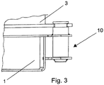
- the Fig. 3 shows a detailed view of the Fig. 2 from above in an end region of the first rod magazine 3 and the second rod magazine 1.
- the second rod magazine 1 is suspended in fork-shaped brackets as second connecting elements 2 of the first rod magazine 3 by means of connecting elements 10 arranged on the end and designed as bolts.
- the second connecting elements 2 are also arranged at the end in the edge region of the first rod magazine 3.
- the tabs extend in a direction parallel to the drill pipe axis offset from this.
- the bolts extend transversely to the longitudinal axis of the second rod magazine 1.
- the bolt, which is designed as a second connecting element 10 of the second rod magazine 1 has a recess. By hanging the bolt in the bracket, it can be fixed in height.
- the tab specifies a reference area or reference point for the height. The turning enables fixation in a position transverse to the drill rod axis and thus offers the possibility of referencing.
Landscapes
- Engineering & Computer Science (AREA)
- Life Sciences & Earth Sciences (AREA)
- Geology (AREA)
- Mining & Mineral Resources (AREA)
- Physics & Mathematics (AREA)
- Environmental & Geological Engineering (AREA)
- Fluid Mechanics (AREA)
- General Life Sciences & Earth Sciences (AREA)
- Geochemistry & Mineralogy (AREA)
- Mechanical Engineering (AREA)
- Earth Drilling (AREA)
Applications Claiming Priority (1)
| Application Number | Priority Date | Filing Date | Title |
|---|---|---|---|
| DE102019001203.8A DE102019001203A1 (de) | 2019-02-20 | 2019-02-20 | Erdbohrvorrichtung, System umfassend eine Erdbohrvorrichtung, Verfahren zum Erdbohren und Verwendung einer Erdbohrvorrichtung |
Publications (2)
| Publication Number | Publication Date |
|---|---|
| EP3699393A1 true EP3699393A1 (fr) | 2020-08-26 |
| EP3699393B1 EP3699393B1 (fr) | 2023-02-15 |
Family
ID=69804379
Family Applications (1)
| Application Number | Title | Priority Date | Filing Date |
|---|---|---|---|
| EP20158147.7A Active EP3699393B1 (fr) | 2019-02-20 | 2020-02-19 | Dispositif de forage du sol, système comprenant un dispositif de forage du sol, procédé de forage du sol et utilisation d'un dispositif de forage du sol |
Country Status (4)
| Country | Link |
|---|---|
| US (1) | US11156040B2 (fr) |
| EP (1) | EP3699393B1 (fr) |
| AU (1) | AU2020201159B2 (fr) |
| DE (1) | DE102019001203A1 (fr) |
Families Citing this family (1)
| Publication number | Priority date | Publication date | Assignee | Title |
|---|---|---|---|---|
| US20200102791A1 (en) | 2018-09-28 | 2020-04-02 | The Toro Company | Underground drill |
Citations (5)
| Publication number | Priority date | Publication date | Assignee | Title |
|---|---|---|---|---|
| EP0919692A2 (fr) * | 1997-11-27 | 1999-06-02 | Johann Haas | Magasin pour tiges de forage et/ou tubages dans des machines de forage de roches |
| DE102009035277A1 (de) | 2009-07-29 | 2011-02-10 | Tracto-Technik Gmbh & Co. Kg | Bohrvorrichtung |
| WO2011120627A2 (fr) * | 2010-04-01 | 2011-10-06 | Herrenknecht Vertical Gmbh | Procédé et dispositif pour l'acheminement et l'évacuation de trains de tiges vers un dispositif de forage |
| EP2803810A1 (fr) * | 2013-05-17 | 2014-11-19 | Sandvik Intellectual Property AB | Appareil de manipulation de tige de forage |
| DE202016008527U1 (de) * | 2016-12-20 | 2018-06-05 | Prime Drilling Gmbh | Horizontal-Bohranlage |
Family Cites Families (8)
| Publication number | Priority date | Publication date | Assignee | Title |
|---|---|---|---|---|
| DE4126919A1 (de) * | 1991-08-14 | 1993-02-18 | Stump Bohr Gmbh | Verfahren und bohrgeraet zum bohren von loechern im erdreich oder fels, insbesondere zur herstellung von verpressankern |
| US6527063B2 (en) * | 2000-02-17 | 2003-03-04 | Wendall D. Rust | Directional boring device |
| US6408954B1 (en) * | 2000-06-23 | 2002-06-25 | Vermeer Manufacturing Company | Gripping mechanism for a directional drilling machine |
| US20030196791A1 (en) * | 2002-02-25 | 2003-10-23 | N-I Energy Development, Inc. | Tubular handling apparatus and method |
| AU2005337415B2 (en) * | 2005-10-07 | 2011-08-18 | Marl Technologies Inc. | Apparatus and method for handling pipe sections |
| US7694751B2 (en) * | 2007-07-12 | 2010-04-13 | Vermeer Manufacturing Company | Apparatus and method of loading a rod box for a horizontal directional drill |
| DE102012007402A1 (de) * | 2012-04-16 | 2013-10-17 | Herrenknecht Vertical Gmbh | Rohrlager und Verfahren zum Zu- und Abführen von Rohrkörpern zu einer Bohranlage |
| US9309728B2 (en) * | 2012-05-14 | 2016-04-12 | Nabors Drilling International Limited | Drilling rig employing tubular handling device |
-
2019
- 2019-02-20 DE DE102019001203.8A patent/DE102019001203A1/de active Pending
-
2020
- 2020-02-10 US US16/786,306 patent/US11156040B2/en active Active
- 2020-02-18 AU AU2020201159A patent/AU2020201159B2/en active Active
- 2020-02-19 EP EP20158147.7A patent/EP3699393B1/fr active Active
Patent Citations (5)
| Publication number | Priority date | Publication date | Assignee | Title |
|---|---|---|---|---|
| EP0919692A2 (fr) * | 1997-11-27 | 1999-06-02 | Johann Haas | Magasin pour tiges de forage et/ou tubages dans des machines de forage de roches |
| DE102009035277A1 (de) | 2009-07-29 | 2011-02-10 | Tracto-Technik Gmbh & Co. Kg | Bohrvorrichtung |
| WO2011120627A2 (fr) * | 2010-04-01 | 2011-10-06 | Herrenknecht Vertical Gmbh | Procédé et dispositif pour l'acheminement et l'évacuation de trains de tiges vers un dispositif de forage |
| EP2803810A1 (fr) * | 2013-05-17 | 2014-11-19 | Sandvik Intellectual Property AB | Appareil de manipulation de tige de forage |
| DE202016008527U1 (de) * | 2016-12-20 | 2018-06-05 | Prime Drilling Gmbh | Horizontal-Bohranlage |
Also Published As
| Publication number | Publication date |
|---|---|
| DE102019001203A1 (de) | 2020-09-03 |
| AU2020201159B2 (en) | 2021-12-16 |
| AU2020201159A1 (en) | 2020-09-03 |
| EP3699393B1 (fr) | 2023-02-15 |
| US20200284108A1 (en) | 2020-09-10 |
| US11156040B2 (en) | 2021-10-26 |
Similar Documents
| Publication | Publication Date | Title |
|---|---|---|
| WO2015043740A1 (fr) | Dispositif de manipulation de tubes de forage d'un dispositif de forage profond | |
| EP0527460B1 (fr) | Procédé et dispositif pour forer des trous dans le sol ou dans la roche, notamment pour le placement de boulons d'ancrage à injection | |
| EP2521834B1 (fr) | Procédé et dispositif pour l'acheminement et l'évacuation de trains de tiges vers un dispositif de forage | |
| DE102009035277B4 (de) | Bohrvorrichtung | |
| DE2400805C3 (de) | Bohrgestängelagereinrichtung | |
| DE102012016878A1 (de) | Bohrstangenhandhabeeinrichtung, Bohrmast für eine Bohranlage und Verfahren zum Bewegen von Bohrstangen an einer Bohranlage | |
| DE2615086A1 (de) | Vorrichtung zum handhaben von bohrfutterrohren | |
| DE102009051583A1 (de) | Robotersystem und Verfahren zum Verlegen eines Schienenstrangs | |
| WO2020193119A1 (fr) | Dispositif de montage et procédé d'exécution d'un processus d'installation dans une cage d'ascenseur d'un système d'ascenseur | |
| DE10108696B4 (de) | Bohrmaschine für das Doppelkopf- und Überlagerungsbohren mit kreisbogenförmigem Gestängemagazin | |
| DE10341437B4 (de) | Bohrgerät mit Gestängemagazin und Gestängemanipuliervorrichtung | |
| EP3699393B1 (fr) | Dispositif de forage du sol, système comprenant un dispositif de forage du sol, procédé de forage du sol et utilisation d'un dispositif de forage du sol | |
| DE10216258B4 (de) | Triebwerkstand | |
| DE202015008972U1 (de) | Bohranlage mit einem zwischen einer Transportstellung und einer Arbeitsstellung schwenkbaren Bohrmast | |
| WO2016008468A1 (fr) | Appareil de forage et de mise en place de boulons d'ancrage à déplacement transversal | |
| EP0919692A2 (fr) | Magasin pour tiges de forage et/ou tubages dans des machines de forage de roches | |
| DE2803831C2 (de) | Verfahren zum Einlegen von Gestängestücken in eine Borhmaschine und Bohrmaschine mit Gestängeeinlegevorrichtung | |
| WO2014154338A1 (fr) | Fixation aimantée pour barres à enfoncer | |
| DE202015008973U1 (de) | Bohranlage mit einem zwischen einer Transportstellung und einer Arbeitsstellung schwenkbaren Mast | |
| EP3696372B1 (fr) | Dispositif de forage du sol et utilisation d'un dispositif de forage du sol | |
| EP3981920B1 (fr) | Dispositif de génie civil et procédé de génie civil permettant d'enlever les sols | |
| DE10104337A1 (de) | Gestängewechseleinrichtung für Horizontalbohrgeräte | |
| DE69421998T2 (de) | Räumanlage für durchgehende Löcher einer Platte und Räumverfahren | |
| EP2381064A2 (fr) | Dispositif de manipulation de tiges de forage, procédé de fonctionnement du dispositif et d'utilisation de moyens pour déplacer un tel dispositif | |
| EP0628663B1 (fr) | Dispositif d'enforcement et de tirage des éléments d'étayage pour construction de tranchées |
Legal Events
| Date | Code | Title | Description |
|---|---|---|---|
| PUAI | Public reference made under article 153(3) epc to a published international application that has entered the european phase |
Free format text: ORIGINAL CODE: 0009012 |
|
| STAA | Information on the status of an ep patent application or granted ep patent |
Free format text: STATUS: THE APPLICATION HAS BEEN PUBLISHED |
|
| AK | Designated contracting states |
Kind code of ref document: A1 Designated state(s): AL AT BE BG CH CY CZ DE DK EE ES FI FR GB GR HR HU IE IS IT LI LT LU LV MC MK MT NL NO PL PT RO RS SE SI SK SM TR |
|
| AX | Request for extension of the european patent |
Extension state: BA ME |
|
| STAA | Information on the status of an ep patent application or granted ep patent |
Free format text: STATUS: REQUEST FOR EXAMINATION WAS MADE |
|
| 17P | Request for examination filed |
Effective date: 20210226 |
|
| RBV | Designated contracting states (corrected) |
Designated state(s): AL AT BE BG CH CY CZ DE DK EE ES FI FR GB GR HR HU IE IS IT LI LT LU LV MC MK MT NL NO PL PT RO RS SE SI SK SM TR |
|
| STAA | Information on the status of an ep patent application or granted ep patent |
Free format text: STATUS: EXAMINATION IS IN PROGRESS |
|
| 17Q | First examination report despatched |
Effective date: 20210806 |
|
| GRAP | Despatch of communication of intention to grant a patent |
Free format text: ORIGINAL CODE: EPIDOSNIGR1 |
|
| STAA | Information on the status of an ep patent application or granted ep patent |
Free format text: STATUS: GRANT OF PATENT IS INTENDED |
|
| INTG | Intention to grant announced |
Effective date: 20220926 |
|
| GRAS | Grant fee paid |
Free format text: ORIGINAL CODE: EPIDOSNIGR3 |
|
| GRAA | (expected) grant |
Free format text: ORIGINAL CODE: 0009210 |
|
| STAA | Information on the status of an ep patent application or granted ep patent |
Free format text: STATUS: THE PATENT HAS BEEN GRANTED |
|
| AK | Designated contracting states |
Kind code of ref document: B1 Designated state(s): AL AT BE BG CH CY CZ DE DK EE ES FI FR GB GR HR HU IE IS IT LI LT LU LV MC MK MT NL NO PL PT RO RS SE SI SK SM TR |
|
| REG | Reference to a national code |
Ref country code: CH Ref legal event code: EP Ref country code: GB Ref legal event code: FG4D Free format text: NOT ENGLISH |
|
| REG | Reference to a national code |
Ref country code: DE Ref legal event code: R096 Ref document number: 502020002495 Country of ref document: DE |
|
| REG | Reference to a national code |
Ref country code: AT Ref legal event code: REF Ref document number: 1548306 Country of ref document: AT Kind code of ref document: T Effective date: 20230315 Ref country code: IE Ref legal event code: FG4D Free format text: LANGUAGE OF EP DOCUMENT: GERMAN |
|
| REG | Reference to a national code |
Ref country code: LT Ref legal event code: MG9D |
|
| REG | Reference to a national code |
Ref country code: NL Ref legal event code: MP Effective date: 20230215 |
|
| P01 | Opt-out of the competence of the unified patent court (upc) registered |
Effective date: 20230526 |
|
| PG25 | Lapsed in a contracting state [announced via postgrant information from national office to epo] |
Ref country code: RS Free format text: LAPSE BECAUSE OF FAILURE TO SUBMIT A TRANSLATION OF THE DESCRIPTION OR TO PAY THE FEE WITHIN THE PRESCRIBED TIME-LIMIT Effective date: 20230215 Ref country code: PT Free format text: LAPSE BECAUSE OF FAILURE TO SUBMIT A TRANSLATION OF THE DESCRIPTION OR TO PAY THE FEE WITHIN THE PRESCRIBED TIME-LIMIT Effective date: 20230615 Ref country code: NO Free format text: LAPSE BECAUSE OF FAILURE TO SUBMIT A TRANSLATION OF THE DESCRIPTION OR TO PAY THE FEE WITHIN THE PRESCRIBED TIME-LIMIT Effective date: 20230515 Ref country code: NL Free format text: LAPSE BECAUSE OF FAILURE TO SUBMIT A TRANSLATION OF THE DESCRIPTION OR TO PAY THE FEE WITHIN THE PRESCRIBED TIME-LIMIT Effective date: 20230215 Ref country code: LV Free format text: LAPSE BECAUSE OF FAILURE TO SUBMIT A TRANSLATION OF THE DESCRIPTION OR TO PAY THE FEE WITHIN THE PRESCRIBED TIME-LIMIT Effective date: 20230215 Ref country code: LT Free format text: LAPSE BECAUSE OF FAILURE TO SUBMIT A TRANSLATION OF THE DESCRIPTION OR TO PAY THE FEE WITHIN THE PRESCRIBED TIME-LIMIT Effective date: 20230215 Ref country code: HR Free format text: LAPSE BECAUSE OF FAILURE TO SUBMIT A TRANSLATION OF THE DESCRIPTION OR TO PAY THE FEE WITHIN THE PRESCRIBED TIME-LIMIT Effective date: 20230215 Ref country code: ES Free format text: LAPSE BECAUSE OF FAILURE TO SUBMIT A TRANSLATION OF THE DESCRIPTION OR TO PAY THE FEE WITHIN THE PRESCRIBED TIME-LIMIT Effective date: 20230215 |
|
| PG25 | Lapsed in a contracting state [announced via postgrant information from national office to epo] |
Ref country code: SE Free format text: LAPSE BECAUSE OF FAILURE TO SUBMIT A TRANSLATION OF THE DESCRIPTION OR TO PAY THE FEE WITHIN THE PRESCRIBED TIME-LIMIT Effective date: 20230215 Ref country code: PL Free format text: LAPSE BECAUSE OF FAILURE TO SUBMIT A TRANSLATION OF THE DESCRIPTION OR TO PAY THE FEE WITHIN THE PRESCRIBED TIME-LIMIT Effective date: 20230215 Ref country code: IS Free format text: LAPSE BECAUSE OF FAILURE TO SUBMIT A TRANSLATION OF THE DESCRIPTION OR TO PAY THE FEE WITHIN THE PRESCRIBED TIME-LIMIT Effective date: 20230615 Ref country code: GR Free format text: LAPSE BECAUSE OF FAILURE TO SUBMIT A TRANSLATION OF THE DESCRIPTION OR TO PAY THE FEE WITHIN THE PRESCRIBED TIME-LIMIT Effective date: 20230516 Ref country code: FI Free format text: LAPSE BECAUSE OF FAILURE TO SUBMIT A TRANSLATION OF THE DESCRIPTION OR TO PAY THE FEE WITHIN THE PRESCRIBED TIME-LIMIT Effective date: 20230215 |
|
| REG | Reference to a national code |
Ref country code: CH Ref legal event code: PL |
|
| REG | Reference to a national code |
Ref country code: BE Ref legal event code: MM Effective date: 20230228 |
|
| PG25 | Lapsed in a contracting state [announced via postgrant information from national office to epo] |
Ref country code: SM Free format text: LAPSE BECAUSE OF FAILURE TO SUBMIT A TRANSLATION OF THE DESCRIPTION OR TO PAY THE FEE WITHIN THE PRESCRIBED TIME-LIMIT Effective date: 20230215 Ref country code: RO Free format text: LAPSE BECAUSE OF FAILURE TO SUBMIT A TRANSLATION OF THE DESCRIPTION OR TO PAY THE FEE WITHIN THE PRESCRIBED TIME-LIMIT Effective date: 20230215 Ref country code: LU Free format text: LAPSE BECAUSE OF NON-PAYMENT OF DUE FEES Effective date: 20230219 Ref country code: LI Free format text: LAPSE BECAUSE OF NON-PAYMENT OF DUE FEES Effective date: 20230228 Ref country code: EE Free format text: LAPSE BECAUSE OF FAILURE TO SUBMIT A TRANSLATION OF THE DESCRIPTION OR TO PAY THE FEE WITHIN THE PRESCRIBED TIME-LIMIT Effective date: 20230215 Ref country code: DK Free format text: LAPSE BECAUSE OF FAILURE TO SUBMIT A TRANSLATION OF THE DESCRIPTION OR TO PAY THE FEE WITHIN THE PRESCRIBED TIME-LIMIT Effective date: 20230215 Ref country code: CZ Free format text: LAPSE BECAUSE OF FAILURE TO SUBMIT A TRANSLATION OF THE DESCRIPTION OR TO PAY THE FEE WITHIN THE PRESCRIBED TIME-LIMIT Effective date: 20230215 Ref country code: CH Free format text: LAPSE BECAUSE OF NON-PAYMENT OF DUE FEES Effective date: 20230228 |
|
| REG | Reference to a national code |
Ref country code: DE Ref legal event code: R097 Ref document number: 502020002495 Country of ref document: DE |
|
| PG25 | Lapsed in a contracting state [announced via postgrant information from national office to epo] |
Ref country code: SK Free format text: LAPSE BECAUSE OF FAILURE TO SUBMIT A TRANSLATION OF THE DESCRIPTION OR TO PAY THE FEE WITHIN THE PRESCRIBED TIME-LIMIT Effective date: 20230215 |
|
| REG | Reference to a national code |
Ref country code: IE Ref legal event code: MM4A |
|
| PLBE | No opposition filed within time limit |
Free format text: ORIGINAL CODE: 0009261 |
|
| STAA | Information on the status of an ep patent application or granted ep patent |
Free format text: STATUS: NO OPPOSITION FILED WITHIN TIME LIMIT |
|
| PG25 | Lapsed in a contracting state [announced via postgrant information from national office to epo] |
Ref country code: MC Free format text: LAPSE BECAUSE OF FAILURE TO SUBMIT A TRANSLATION OF THE DESCRIPTION OR TO PAY THE FEE WITHIN THE PRESCRIBED TIME-LIMIT Effective date: 20230215 |
|
| 26N | No opposition filed |
Effective date: 20231116 |
|
| PG25 | Lapsed in a contracting state [announced via postgrant information from national office to epo] |
Ref country code: SI Free format text: LAPSE BECAUSE OF FAILURE TO SUBMIT A TRANSLATION OF THE DESCRIPTION OR TO PAY THE FEE WITHIN THE PRESCRIBED TIME-LIMIT Effective date: 20230215 Ref country code: MC Free format text: LAPSE BECAUSE OF FAILURE TO SUBMIT A TRANSLATION OF THE DESCRIPTION OR TO PAY THE FEE WITHIN THE PRESCRIBED TIME-LIMIT Effective date: 20230215 Ref country code: IE Free format text: LAPSE BECAUSE OF NON-PAYMENT OF DUE FEES Effective date: 20230219 |
|
| PG25 | Lapsed in a contracting state [announced via postgrant information from national office to epo] |
Ref country code: BE Free format text: LAPSE BECAUSE OF NON-PAYMENT OF DUE FEES Effective date: 20230228 |
|
| PG25 | Lapsed in a contracting state [announced via postgrant information from national office to epo] |
Ref country code: IT Free format text: LAPSE BECAUSE OF FAILURE TO SUBMIT A TRANSLATION OF THE DESCRIPTION OR TO PAY THE FEE WITHIN THE PRESCRIBED TIME-LIMIT Effective date: 20230215 |
|
| PG25 | Lapsed in a contracting state [announced via postgrant information from national office to epo] |
Ref country code: BG Free format text: LAPSE BECAUSE OF FAILURE TO SUBMIT A TRANSLATION OF THE DESCRIPTION OR TO PAY THE FEE WITHIN THE PRESCRIBED TIME-LIMIT Effective date: 20230215 |
|
| PG25 | Lapsed in a contracting state [announced via postgrant information from national office to epo] |
Ref country code: BG Free format text: LAPSE BECAUSE OF FAILURE TO SUBMIT A TRANSLATION OF THE DESCRIPTION OR TO PAY THE FEE WITHIN THE PRESCRIBED TIME-LIMIT Effective date: 20230215 |
|
| PGFP | Annual fee paid to national office [announced via postgrant information from national office to epo] |
Ref country code: AT Payment date: 20250417 Year of fee payment: 5 |
|
| REG | Reference to a national code |
Ref country code: DE Ref legal event code: R082 Ref document number: 502020002495 Country of ref document: DE Representative=s name: HOFFMANN EITLE PATENT- UND RECHTSANWAELTE PART, DE |
|
| PG25 | Lapsed in a contracting state [announced via postgrant information from national office to epo] |
Ref country code: CY Free format text: LAPSE BECAUSE OF FAILURE TO SUBMIT A TRANSLATION OF THE DESCRIPTION OR TO PAY THE FEE WITHIN THE PRESCRIBED TIME-LIMIT; INVALID AB INITIO Effective date: 20200219 |
|
| PG25 | Lapsed in a contracting state [announced via postgrant information from national office to epo] |
Ref country code: HU Free format text: LAPSE BECAUSE OF FAILURE TO SUBMIT A TRANSLATION OF THE DESCRIPTION OR TO PAY THE FEE WITHIN THE PRESCRIBED TIME-LIMIT; INVALID AB INITIO Effective date: 20200219 |
|
| PG25 | Lapsed in a contracting state [announced via postgrant information from national office to epo] |
Ref country code: TR Free format text: LAPSE BECAUSE OF FAILURE TO SUBMIT A TRANSLATION OF THE DESCRIPTION OR TO PAY THE FEE WITHIN THE PRESCRIBED TIME-LIMIT Effective date: 20230215 |
|
| PGFP | Annual fee paid to national office [announced via postgrant information from national office to epo] |
Ref country code: GB Payment date: 20260219 Year of fee payment: 7 |
|
| PGFP | Annual fee paid to national office [announced via postgrant information from national office to epo] |
Ref country code: DE Payment date: 20260217 Year of fee payment: 7 |
|
| PG25 | Lapsed in a contracting state [announced via postgrant information from national office to epo] |
Ref country code: AT Free format text: LAPSE BECAUSE OF NON-PAYMENT OF DUE FEES Effective date: 20250219 |
|
| REG | Reference to a national code |
Ref country code: AT Ref legal event code: MM01 Ref document number: 1548306 Country of ref document: AT Kind code of ref document: T Effective date: 20250219 |
|
| PGFP | Annual fee paid to national office [announced via postgrant information from national office to epo] |
Ref country code: FR Payment date: 20260223 Year of fee payment: 7 |