EP3699401A1 - Halterungsvorrichtung für mindestens ein kühlrohr an einem gehäuse eines turbotriebwerks, und zugehöriges montageverfahren - Google Patents
Halterungsvorrichtung für mindestens ein kühlrohr an einem gehäuse eines turbotriebwerks, und zugehöriges montageverfahren Download PDFInfo
- Publication number
- EP3699401A1 EP3699401A1 EP20157210.4A EP20157210A EP3699401A1 EP 3699401 A1 EP3699401 A1 EP 3699401A1 EP 20157210 A EP20157210 A EP 20157210A EP 3699401 A1 EP3699401 A1 EP 3699401A1
- Authority
- EP
- European Patent Office
- Prior art keywords
- support
- cooling tube
- tube
- cooling
- leg
- Prior art date
- Legal status (The legal status is an assumption and is not a legal conclusion. Google has not performed a legal analysis and makes no representation as to the accuracy of the status listed.)
- Granted
Links
Images








Classifications
-
- F—MECHANICAL ENGINEERING; LIGHTING; HEATING; WEAPONS; BLASTING
- F01—MACHINES OR ENGINES IN GENERAL; ENGINE PLANTS IN GENERAL; STEAM ENGINES
- F01D—NON-POSITIVE DISPLACEMENT MACHINES OR ENGINES, e.g. STEAM TURBINES
- F01D11/00—Preventing or minimising internal leakage of working-fluid, e.g. between stages
- F01D11/08—Preventing or minimising internal leakage of working-fluid, e.g. between stages for sealing space between rotor blade tips and stator
- F01D11/14—Adjusting or regulating tip-clearance, i.e. distance between rotor-blade tips and stator casing
- F01D11/20—Actively adjusting tip-clearance
- F01D11/24—Actively adjusting tip-clearance by selectively cooling-heating stator or rotor components
-
- F—MECHANICAL ENGINEERING; LIGHTING; HEATING; WEAPONS; BLASTING
- F01—MACHINES OR ENGINES IN GENERAL; ENGINE PLANTS IN GENERAL; STEAM ENGINES
- F01D—NON-POSITIVE DISPLACEMENT MACHINES OR ENGINES, e.g. STEAM TURBINES
- F01D25/00—Component parts, details, or accessories, not provided for in, or of interest apart from, other groups
- F01D25/28—Supporting or mounting arrangements, e.g. for turbine casing
-
- F—MECHANICAL ENGINEERING; LIGHTING; HEATING; WEAPONS; BLASTING
- F01—MACHINES OR ENGINES IN GENERAL; ENGINE PLANTS IN GENERAL; STEAM ENGINES
- F01D—NON-POSITIVE DISPLACEMENT MACHINES OR ENGINES, e.g. STEAM TURBINES
- F01D25/00—Component parts, details, or accessories, not provided for in, or of interest apart from, other groups
- F01D25/08—Cooling; Heating; Heat-insulation
- F01D25/12—Cooling
-
- F—MECHANICAL ENGINEERING; LIGHTING; HEATING; WEAPONS; BLASTING
- F01—MACHINES OR ENGINES IN GENERAL; ENGINE PLANTS IN GENERAL; STEAM ENGINES
- F01D—NON-POSITIVE DISPLACEMENT MACHINES OR ENGINES, e.g. STEAM TURBINES
- F01D25/00—Component parts, details, or accessories, not provided for in, or of interest apart from, other groups
- F01D25/08—Cooling; Heating; Heat-insulation
- F01D25/14—Casings modified therefor
-
- F—MECHANICAL ENGINEERING; LIGHTING; HEATING; WEAPONS; BLASTING
- F02—COMBUSTION ENGINES; HOT-GAS OR COMBUSTION-PRODUCT ENGINE PLANTS
- F02C—GAS-TURBINE PLANTS; AIR INTAKES FOR JET-PROPULSION PLANTS; CONTROLLING FUEL SUPPLY IN AIR-BREATHING JET-PROPULSION PLANTS
- F02C7/00—Features, components parts, details or accessories, not provided for in, or of interest apart form groups F02C1/00 - F02C6/00; Air intakes for jet-propulsion plants
- F02C7/12—Cooling of plants
- F02C7/16—Cooling of plants characterised by cooling medium
- F02C7/18—Cooling of plants characterised by cooling medium the medium being gaseous, e.g. air
-
- F—MECHANICAL ENGINEERING; LIGHTING; HEATING; WEAPONS; BLASTING
- F05—INDEXING SCHEMES RELATING TO ENGINES OR PUMPS IN VARIOUS SUBCLASSES OF CLASSES F01-F04
- F05D—INDEXING SCHEME FOR ASPECTS RELATING TO NON-POSITIVE-DISPLACEMENT MACHINES OR ENGINES, GAS-TURBINES OR JET-PROPULSION PLANTS
- F05D2240/00—Components
- F05D2240/90—Mounting on supporting structures or systems
-
- F—MECHANICAL ENGINEERING; LIGHTING; HEATING; WEAPONS; BLASTING
- F05—INDEXING SCHEMES RELATING TO ENGINES OR PUMPS IN VARIOUS SUBCLASSES OF CLASSES F01-F04
- F05D—INDEXING SCHEME FOR ASPECTS RELATING TO NON-POSITIVE-DISPLACEMENT MACHINES OR ENGINES, GAS-TURBINES OR JET-PROPULSION PLANTS
- F05D2260/00—Function
- F05D2260/20—Heat transfer, e.g. cooling
-
- F—MECHANICAL ENGINEERING; LIGHTING; HEATING; WEAPONS; BLASTING
- F05—INDEXING SCHEMES RELATING TO ENGINES OR PUMPS IN VARIOUS SUBCLASSES OF CLASSES F01-F04
- F05D—INDEXING SCHEME FOR ASPECTS RELATING TO NON-POSITIVE-DISPLACEMENT MACHINES OR ENGINES, GAS-TURBINES OR JET-PROPULSION PLANTS
- F05D2260/00—Function
- F05D2260/20—Heat transfer, e.g. cooling
- F05D2260/201—Heat transfer, e.g. cooling by impingement of a fluid
-
- F—MECHANICAL ENGINEERING; LIGHTING; HEATING; WEAPONS; BLASTING
- F05—INDEXING SCHEMES RELATING TO ENGINES OR PUMPS IN VARIOUS SUBCLASSES OF CLASSES F01-F04
- F05D—INDEXING SCHEME FOR ASPECTS RELATING TO NON-POSITIVE-DISPLACEMENT MACHINES OR ENGINES, GAS-TURBINES OR JET-PROPULSION PLANTS
- F05D2260/00—Function
- F05D2260/30—Retaining components in desired mutual position
-
- Y—GENERAL TAGGING OF NEW TECHNOLOGICAL DEVELOPMENTS; GENERAL TAGGING OF CROSS-SECTIONAL TECHNOLOGIES SPANNING OVER SEVERAL SECTIONS OF THE IPC; TECHNICAL SUBJECTS COVERED BY FORMER USPC CROSS-REFERENCE ART COLLECTIONS [XRACs] AND DIGESTS
- Y02—TECHNOLOGIES OR APPLICATIONS FOR MITIGATION OR ADAPTATION AGAINST CLIMATE CHANGE
- Y02T—CLIMATE CHANGE MITIGATION TECHNOLOGIES RELATED TO TRANSPORTATION
- Y02T50/00—Aeronautics or air transport
- Y02T50/60—Efficient propulsion technologies, e.g. for aircraft
Definitions
- the invention relates to a device for maintaining at least one cooling tube on a turbomachine casing, as well as a method of mounting the latter.
- One field of application relates to aircraft turbojets.
- the casing may be that of a low pressure turbine of the turbomachine.
- the cooling tube is also called the cooling ramp.
- several cooling tubes are provided.
- the cooling device is fixed with respect to the external surface of the casing in order to maintain the cooling tube or tubes around the latter, so as to cool it as homogeneously as possible.
- the document FR-A-3 040 429 relates to a fastening device comprising a support having an inner sheet and an outer sheet each having grooves each surrounding one half of the circumference of the cooling ramps, flat areas of the sheets being assembled by screws on support elements fixed to the housing .
- the document FR-A-2 995 022 relates to a fixing device comprising a fixing plate comprising recesses on which are fixed fixing collars surrounding the cooling tubes.
- the document FR-A-3 021 700 relates to a fixing device comprising two plates fixed together by spacers defining between them spaces through which the cooling tubes pass.
- the document FR-A-3 002 590 relates to a fastening device comprising a fastening plate having openings and external tabs to which are fixed fastening collars, the fastening collars surrounding the cooling tubes and passing through the openings.
- the holding device creates an overhang on the cooling tubes, which must be supported in order to better control the air gap between the cooling tubes and the outer surface of the casing over the entire periphery thereof.
- the invention aims to obtain a device for maintaining at least one cooling tube on a turbomachine casing, as well as a method for mounting the latter, which make it possible to reduce the air gap between the tube and the casing and 'improve cooling.
- a first object of the invention is a device for holding at least one air-jet cooling tube, the air-jet cooling tube being intended to cool an outer surface of a casing.
- turbomachine characterized in that the holding device comprises a first support, comprising a first internal face turned towards the cooling tube and at least one left partial retaining tab towards the left of the cooling tube, located on the side of the first internal face and fixed to the latter, a second support, comprising a second internal face turned towards the cooling tube and at least one straight partial retaining tab towards the right of the cooling tube, located on the side of the second internal face and fixed to the latter, first means for fixing the first support to a first flange of the housing, second fixing means of the second support to a second flange of the casing, the second fixing means being separate from the first fixing means.
- the invention makes it possible to reduce the bulk under the tube and to bring the tube closer to the external surface of the casing. It is thus possible to reduce the air gap between the cooling tube and the outer surface of the casing, without risking contact between the tabs and the casing.
- the invention also makes it possible to reduce the total mass of the holding device.
- the invention also makes it possible to less block the bores of the tubes sending jets of air towards the outer surface of the casing.
- the left leg is offset with respect to the right leg in a longitudinal direction of the cooling tube.
- the left leg has a left free end portion for supporting the cooling tube which extends obliquely to the right, and / or the right leg has a right free end part supporting the cooling tube which extends obliquely to the left.
- the left lug comprises a first middle part, which is connected to the first internal face and which occupies a first angular sector, the first angular sector being arranged opposite the first support, the left free end part being connected to the first middle part and forming a second angular sector around the cooling tube, the second angular sector being intended to be placed opposite the outer surface of the housing,
- the right leg comprises a second middle part, which is connected to the second internal face and which occupies a third angular sector, the third angular sector being arranged opposite the second support, the right free end part being connected to the second middle part and forming a fourth angular sector around the cooling tube, the fourth angular sector being intended to be placed opposite the outer surface of the housing.
- the left end part of the left leg and the right end part of the right leg each comprise a radially inner free end
- the tube comprises a radially inner free end, the the radially inner free end of the tube being located radially under the radially inner free end of each of the legs.
- the second angular sector around the cooling tube extends from 180 ° to a maximum end value less than or equal to 250 ° and / or the fourth angular sector extends from 0 ° to a maximum end value greater than or equal to -55 °, the angular sectors being referenced with respect to a point of the tube, which is located on the side of the casing and which is taken at 270 °.
- the first support is placed against the second support in a longitudinal direction of the cooling tube.
- the first support comprises at least a first slide part
- the second support comprises at least a second slide part, able to slide against the first slide part along a transverse direction going between the right and the left and / or along a longitudinal direction of the cooling tube to a mounting position, in which the left leg and the right leg are against respectively the left and the right of the cooling tube.
- the first and second fixing means making it possible to immobilize the first and second supports in the mounting position.
- the first support or the second support comprises at least one sliding stopper, configured to stop the sliding of the second support or of the first support in the transverse direction in the mounting position, and / or the first support or the second support comprises at least one other sliding stopper, configured to stop the sliding of the second support or of the first support in the longitudinal direction of the cooling tube in the mounting position.
- the first support comprises a plurality of left legs for partially retaining to the left of respectively a plurality of cooling tubes
- the second support comprises a plurality of straight legs for partial retaining to the right of the plurality of cooling tubes, respectively, the plurality of cooling tubes being distributed between the right and the left, the left legs being distributed between the right and the left, the right legs being distributed between the right and the left.
- the left partial retention tabs are distributed one behind the other in a transverse direction going between the right and the left and / or the right partial retention tabs are distributed one after the other. behind the other in the transverse direction.
- the first internal face is flat and / or the second internal face is flat.
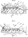
- a second object of the invention is a method of mounting at least one cooling tube on a turbomachine casing using the holding device as described above, characterized in that during a first step, the at least one cooling tube is positioned around an external surface of the turbomachine casing, during a second step subsequent to the first step, the first support of the holding device is positioned to place the left leg against the left of the cooling tube, during a third step subsequent to the second step, the first support is fixed to a first flange of the housing, during a fourth step subsequent to the third step, the second support of the holding device is positioned against the first support in order to place the right leg against the right of the cooling tube, during a fifth step subsequent to the fourth step, the second support is fixed to a second flange of the housing.
- turbomachine 10 on which the device 100 for maintaining at at least one cooling tube T on the outside of an external surface 190 of a casing of this turbomachine 10 according to the invention.
- turbomachine 10 shown in figure 1 is intended to be installed on an aircraft not shown in order to propel it into the air.
- the gas turbine engine or turbomachine assembly 10 has an axis AX, oriented from upstream to downstream or from front to rear or from left to right in what follows.
- the direction from the inside to the outside is the radial direction DR starting from the axis AX.
- the term axially designates a direction along the axis AX.
- An axial plane is a plane containing the axis AX.
- a direction located in a plane transverse to the axis AX is called the transverse direction.
- the turbomachine 10 is for example with a double body.
- the turbomachine 10 comprises a fan assembly 28 and a central gas turbine engine 130.
- the central gas turbine engine 130 comprises, from upstream to downstream in the direction of gas flow, a low pressure compressor. CBP1, a high pressure compressor CHP1, a combustion chamber 160, a high pressure turbine THP1 and a low pressure turbine TBP1 which delimit a primary flow of gas FP1.
- the fan assembly 28 includes a set of fan blades extending radially outward from a rotor 250.
- the turbomachine 10 has an inlet upstream end 29 and an exhaust downstream end 31.
- the turbomachine 10 comprises also an inter-vein casing 36 which delimits a primary vein in which circulates the primary flow FP1 which passes through the high pressure compressor CHP1, the high pressure turbine THP1 and the low pressure turbine TBP1.
- the inter-vein casing 36 comprises, from upstream to downstream, a casing 361 of the low pressure compressor CBP1, an intermediate casing 260, which is interposed between the low pressure compressor CBP1 and the high pressure compressor CHP1, a casing 362 of the high pressure compressor CHP1, a casing 363 of the high pressure turbine THP1 and a casing 19 of the low pressure turbine TBP1.
- the high pressure turbine THP1 is integral with the high pressure compressor CHP1 so as to form a high pressure body, while the low turbine pressure TBP1 is integral with the low pressure compressor CBP1 so as to form a low pressure body, so that each turbine drives the associated compressor in rotation around the axis AX under the effect of the thrust of the gases coming from the combustion chamber 160.
- the turbomachine 10 also includes a secondary stream 39 which is used to pass a secondary stream FS1 of the air stream discharged from the fan assembly 28 around the inter-stream casing 36. More specifically, the secondary stream 39 extends between a internal wall 201 of a fan or nacelle 30 fairing 30 and the inter-vein casing 36 surrounding the central gas turbine engine 130. Arms 34 connect the intermediate casing 260 to the internal wall 201 of the fairing 30 in the secon vein daire 39 of the secondary flow FS1.
- the holding device 100 makes it possible to maintain one or more cooling tubes T or one or more cooling ramps R, at a certain distance radially above the outer surface 190 of the casing and comprises fixing means to this casing, this casing belonging to the inter-vein casing 36, this casing being in particular the casing 19 of the low pressure turbine TBP1 in the embodiments described below and possibly being one of the casing 361 of the compressor low pressure CBP1, the intermediate casing 260, the casing 362 of the high pressure compressor CHP1, the casing 363 of the high pressure turbine THP1 and the casing 19 of the low pressure turbine TBP1.
- a device DE for sending air is provided for sending air under pressure into the cooling tube or tubes T and thus projecting the jets of pressurized air through their orifices OR against the outer surface 190 of the casing 19.
- the pressurized air passing through these OR orifices provides ventilation by impact of the casing 19.
- several cooling tubes T arranged axially side by side are provided.
- several angular ranges are provided, which go around the casing 19 and in each of which there are one or more cooling tubes T arranged side by side axially, for example four angular ranges each of approximately 90 °.
- the casing 19 of the low pressure turbine TBP1 is of general shape having an outer surface 190 widening from upstream to downstream, for example substantially frustoconical, and the cooling tubes T are arranged in transverse planes side by side. side axially, having with respect to the axis AX of the casing 19 a radial distance increasing from upstream to downstream to follow the outer surface 190.
- This cooling system for the casing of the low pressure turbine TBP1 can be of the LPTCC type (in English: Low Pressure Turbine Clearance Control) or else of the LPTACC type (in English: Low Pressure Turbine Active Clearance Control).
- Air is taken from the secondary flow FS1 at the low pressure compressor CBP1, then is routed to the cooling ramps R and / or to the cooling tube (s) T via the various elements described below of the device DE for sending air.
- the flow in the system is directly proportional to the flow in the secondary flow (the sampling flow).
- the flow rate is controlled via a motorized valve connected to the computer as a function of the flight phases (take-off, ascent, cruise, etc.).
- the housing 19 is equipped with two housings B, positioned at approximately 180 ° to each other (only one being visible on the figure 2 ).
- Each box B is equipped with, for example, five ramps R.
- Each ramp R comprises, for example, two cooling tubes T fixed on either side of the box B.
- the devices 100 for holding the cooling ramps R or cooling tubes T are fixed to the casing 19 by an upstream BAM flange and by a BAV downstream flange. Although this is not shown, the boxes B are fixed to the housing 19 in the same way.
- One or more retaining devices 100 may be provided around the casing 19, for example four retaining devices 100.
- the holding device 100 is described in more detail below with reference to figures 3 to 11 .
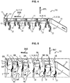
- the holding device 100 comprises a first support 1 supporting at least one lug 12 bearing against the left of at least one cooling tube T and a second support 2 supporting at least one lug 22 bearing against the right of this. cooling T tube.
- the leg (s) 12 are called left leg (s) 12.
- the leg (s) 22 are called right leg (s) 22.
- the first support 1 has a first internal face 11 turned towards the cooling tube T and towards the external surface 190 of the casing 19.
- Each left tab 12 is fixed to the first internal face 11, which may for example be flat, of the support 1 and is located on the side of it.
- the second support 2 has a second internal face 21 turned towards the cooling tube T and towards the external surface 190 of the casing 19.
- Each straight tab 22 is fixed to the second internal face 21, which may for example be flat, of the support 2 and is located on the side of it.
- Each face 11 and / or 21 can be formed from a metal sheet.
- Each left leg 12 is configured to partially retain the cooling tube T, that is to say to partially support the cooling tube T partially radially, namely towards the first internal face 11 and / or in both directions of the inside to outside, working from the left side of the cooling tube T.
- Each straight tab 22 is configured to partially radially retain the cooling tube T, that is to say to partially support the cooling tube T, namely towards the second internal face 21 and / or in both directions of the inside to outside, working from the right of the cooling tube T.
- the left leg 12 cooperates with the right leg 22 to retain the cooling tube T on the right and on the left, as well as radially, namely in both directions from the inside to the outside.
- the left leg 12 and the right leg 22 thus leave free the TCI side of the tube T facing towards the housing 19, that is to say facing radially inward.
- the left leg 12 and the right leg 22 are thus at a distance from the air jet orifices OR of the cooling tube T distributed on this side TCI of the tube T facing the casing 19.
- the cooling tube T can thus be brought closer to the casing 19 to have a smaller air gap E, delimited directly between the cooling tube T and the casing 19, without parts of the retaining device 100 encroaching on this air gap E and therefore avoiding the need for fixing collars depending on the condition of technique enter this gap.
- the tabs 12 and 22 are thus at a distance from the air gap E delimited by the cooling tube T and the outer surface 190 of the casing 19, while making it possible to immobilize the cooling tube T in both directions of the radial direction DR . Obtaining a smaller air gap E makes it possible to improve the cooling performance and therefore the performance of the TBP1 turbine.
- the retaining device 100 comprises first means 13 for fixing the first support 1 to a first flange of the casing 19, and second means 23 for fixing the second support 2 to a second flange of the casing 19, the second fixing means 23 being separate from the first fixing means 13.
- the first flange can be for example the upstream flange BAM and the second flange can be for example the downstream flange BAV, as shown in figures 12 to 19 .
- the first flange can be for example the downstream flange BAV and the second flange can be for example the upstream flange BAM.
- the first fixing means 13 may comprise a first end wing 131 and one or more bolts 132 for fixing the first end wing 131 to the first flange.
- the second fixing means 23 may comprise a second end wing 231 and one or more bolts 232 for fixing the second end wing 231 to the second flange.
- the left leg 12 is offset with respect to the right leg 22 in a longitudinal direction DLT of the tube T of cooling.
- the left leg 12 is entirely offset longitudinally with respect to the right leg 22, that is to say that no part of the left leg 12 is opposite the right leg 22 for the same cooling tube T .
- the term longitudinally designates a direction along the longitudinal DLT direction in which the cooling tube T extends around the casing 19, this longitudinal DLT direction being situated in a transverse plane.
- this longitudinal DLT direction is a circumferential or tangential direction with respect to the radial direction DR.
- the invention thus makes it possible to distribute the contact forces of the holding device 100 along the tube T.
- the first support 1 comprises several left tabs 12 for partially retaining to the left of respectively several cooling tubes T distributed between the right and the left.
- the left partial retaining tabs 12 are distributed from the right to the left radially under the support 1.
- the second support 2 comprises several right tabs 22 for partial retaining to the right of these cooling tubes, respectively, distributed between the right and the left .
- the right partial retaining tabs 22 are also distributed from right to left radially under the support 2.
- the left partial retention tabs 12 are distributed one behind the other in a transverse direction DGS going from right to left and / or the right partial retention tabs 22 are distributed one behind the other according to the DGS transversal direction.
- five left tabs 12 located radially under the internal face 11 and five right tabs 22 located radially under the internal face 21 are provided, respectively to retain five T tubes distributed from right to left.
- the left tab 12 and / or the right tab 22 has a curved hook shape.
- the left tab 12 has a left free end portion 121 for supporting the cooling tube T obliquely to the right and towards the first internal face 11, and / or the right tab 22 at a part 221 of the right free end for supporting the cooling tube T obliquely towards the left and towards the second internal face 21.
- the left end part 121 of the left leg 12 and the right end part 122 of the right leg 22 each comprise a radially internal free end (free end of the part 221 and free end of part 122), and tube T comprises a radially internal free end, the radially internal free end of tube T being located radially under the radially internal free end of each of the tabs 12, 22.
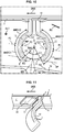
- the left tab 12 comprises a first middle part 122, which is connected to the first internal face 11 and which occupies a first angular sector ANG122 disposed opposite the first support 1.
- This first angular sector ANG122 goes up to 180 ° (point P2) around the cooling tube T, as shown in figure 10 , where the angular values are referenced in an axial plane with respect to a point P1 located on the TCI side of the cooling tube T, facing the outer surface 190 of the housing 19 and which is taken in this case at 270 ° or -90 °.
- the left free end part 121 is connected to the first middle part 122.
- the left free end part 121 forms a second angular sector ANG121 around the cooling tube T.
- This second angular sector ANG121 extends towards the inside the first angular sector ANG122 and is intended to be placed facing the external surface 190 of the casing 19.
- This second angular sector ANG121 extends from 180 ° to a maximum end value lower (free end) to 270 °, which may be less than or equal to 250 °, and in particular less than or equal to 235 °.
- the right leg 22 comprises a second middle part 222, which is connected to the second internal face 21 and which occupies a third angular sector ANG222 disposed opposite the second support 2.
- This third angular sector ANG222 goes up to 0 ° (point P3) around the cooling tube T.
- the right free end part 221 is connected to the second middle part 222.
- the right free end part 221 forms a fourth angular sector ANG221 around the cooling tube T.
- This fourth angular sector ANG221 extends inwardly the third angular sector ANG222 and is intended to be disposed opposite the outer surface (190) of the housing (19).
- This fourth angular sector ANG221 extends from 0 ° to a maximum end value (free end) greater than -90 °, which may be greater than or equal to -70 °, and in particular greater than or equal to -55 °.
- the left leg 12 and the right leg 22 extend to a straight line DP, which is parallel to the outer surface 190 of the housing 19 and which is tangent to the cooling tube T, as shown for example on figure 10 .
- the left leg 12 and the right leg 22 define for example an opening angle ANG inwards, which is greater than 40 °, and for example greater than or equal to 70 °, as shown for example on figure 10 .
- the left tab 12 (part 121 and / or 122) has a rounded shape of contact with the left of the cooling tube T and is for example in the form of a cylinder portion corresponding to the surface external TS of the cooling tube T.
- the straight tab 22 has a rounded shape (part 221 and / or 222) in contact with the straight line of the cooling tube T and is for example in the form of a cylinder portion corresponding to the external surface TS of the cooling tube T.
- the first support 1 is distinct from the second support 2.
- the first support 1 is placed against the second support 2 at least along the longitudinal direction DLT of the cooling tube T and for example also along the DGS transverse direction going between right and left.
- the first support 1 comprises at least a first part 14 and / or 17 of the slide.
- the second support 2 comprises at least a second slide part 24, able to slide against the first slide part 14 along the DGS transverse direction going between the right and the left to a mounting position and / or at least a second slide part 27, able to slide against the first slide part 17 along the longitudinal direction DLT of the tube T cooling to the installation position.
- the left leg 21 and the right leg 22 are respectively against the left and the right of the cooling tube T, as described above.
- the first and second fixing means 13, 23 make it possible to immobilize the first and second supports 1, 2 in the mounting position.
- the slide parts thus make it possible to guide the assembly of the supports 1 and 2 against each other.
- the first slide part 14 and / or 17 may be a female slide part, in which the second slide part 24 and / or 27 is able to slide, or conversely the second slide part 24 and / or 27 may be a slide.
- female slide part in which the first slide part 14 and / or 17 is able to slide.
- the first support 1 comprises at least one stop 15 and / or 25 for the sliding stop, configured to stop the sliding of the second support 2 in the transverse direction DGS up to the mounting position.
- the stop 15 can be formed by the first part 17 of the slide.
- the second support 2 comprises at least one sliding stop stop, configured to stop the sliding of the first support 1 in the transverse direction DGS to the mounting position. This stop may be formed by the second part 27 of slide 27.
- the first support 1 comprises at least one other sliding stop stop 16, configured to stop the sliding of the second support 2 in the longitudinal direction DLT of the cooling tube T to the mounting position.
- the other stop 16 can be formed by the first part 14 of the slide.
- the second support 2 comprises at least one other sliding stop stop, configured to stop the sliding of the first support 1 in the longitudinal direction DLT of the cooling tube T to the mounting position.
- This other stop may be formed by the second part 24 of the slide.
- the support 1 and / or the support 2 can be for example a sheet on which are extruded via metal additive manufacturing the left leg (s) 12 and / or the or the right leg (s) 22.
- the left leg (s) 12 and / or the right leg (s) 22 can also be manufactured in a conventional manner (together mechanically welded or other)
- each left leg 12 and / or each right leg 22 is covered with a damping envelope 3 made of a flexible material (for example silica wool or others). This is to prevent damage to the T-tubes during assembly or in cases of abnormal operation.
- a damping envelope 3 can be retained on the left leg 12 and / or on the right leg 22 by a toothed plate 32, which is fixed (for example by welding) to the first internal face 11 or to the second internal face 21 and whose teeth 33 press against the casing 3.
- the cooling tube or tubes T are positioned around the outer surface 190 of the casing 19 of the turbomachine. This positioning is for example carried out by installing the box or boxes B on the casing 19 and / or by installing the device DE for sending air to the turbomachine 10.
- the first support 1 is positioned to place the left leg or legs 12 against the left of the cooling tube or tubes T.
- the first support 1 is fixed to the first flange (for example BAM) of the casing 19 by the first fixing means 13, for example using the bolt or bolts 132, as described above.
- the second support 2 of the device is positioned 100 for holding against the first support 1 to have the right tab 22 against the right of the cooling tube T.
- This fourth step E4 comprises for example first a first sub-step E41 (shown in figure 15 ) bringing the second support 2 away from the support 1 in order to pass the straight leg (s) 22 away from the tubes T and between the tubes T, then a second sub-step E42 (shown in figure 16 ) docking of the second part 24 of slide 24 against the first part 14 of slide 14 in the longitudinal direction DLT of the cooling tube T so that the second support 2 comes against the other stop 16, then a third sub-step E41 (shown on figure 17 ), in which the second part 24 of slide 24 of the second support 2 is slid in the transverse direction DGS from right to left against the first part 14 of slide 14 of the first support 1 until the second support 2 abuts against stop 15 and / or 25.
- the second support 2 is fixed to the second flange (for example BAV) of the casing 19 by the second fixing means 23, for example using the bolting (s) 232, as described above.
- This process allows gentle assembly without risking damage to the tubes and does not require flexibility in the tabs 12, 22 themselves, this flexibility running the risk of causing them to break prematurely and losing the mechanical strength of the tube T.
- the invention makes it possible to do away with screws and therefore a saving in mass.
- the diameter of the ramps being conditioned by the passage of the tools allowing the assembly of the holding device and the screws on the ramp support, these diameters can be increased.
Landscapes
- Engineering & Computer Science (AREA)
- Mechanical Engineering (AREA)
- General Engineering & Computer Science (AREA)
- Chemical & Material Sciences (AREA)
- Combustion & Propulsion (AREA)
- Turbine Rotor Nozzle Sealing (AREA)
- Structures Of Non-Positive Displacement Pumps (AREA)
Applications Claiming Priority (1)
| Application Number | Priority Date | Filing Date | Title |
|---|---|---|---|
| FR1901905A FR3093129B1 (fr) | 2019-02-25 | 2019-02-25 | Dispositif de maintien d’au moins un tube de refroidissement à un carter de turbomachine et son procédé de montage |
Publications (2)
| Publication Number | Publication Date |
|---|---|
| EP3699401A1 true EP3699401A1 (de) | 2020-08-26 |
| EP3699401B1 EP3699401B1 (de) | 2021-07-21 |
Family
ID=67185344
Family Applications (1)
| Application Number | Title | Priority Date | Filing Date |
|---|---|---|---|
| EP20157210.4A Active EP3699401B1 (de) | 2019-02-25 | 2020-02-13 | Halterungsvorrichtung für mindestens ein kühlrohr an einem gehäuse eines turbotriebwerks, und zugehöriges montageverfahren |
Country Status (4)
| Country | Link |
|---|---|
| US (1) | US11225906B2 (de) |
| EP (1) | EP3699401B1 (de) |
| CN (1) | CN111608746B (de) |
| FR (1) | FR3093129B1 (de) |
Cited By (3)
| Publication number | Priority date | Publication date | Assignee | Title |
|---|---|---|---|---|
| FR3114346A1 (fr) * | 2020-09-24 | 2022-03-25 | Safran Aircraft Engines | Carter de turbine de turboréacteur équipé de support de fixation de tubes de refroidissement |
| FR3122451A1 (fr) * | 2021-05-03 | 2022-11-04 | Safran Aircraft Engines | Turboréacteur |
| CN115341968A (zh) * | 2022-06-27 | 2022-11-15 | 中国北方发动机研究所(天津) | 一种超临界二氧化碳涡轮发电冷却装置 |
Families Citing this family (2)
| Publication number | Priority date | Publication date | Assignee | Title |
|---|---|---|---|---|
| FR3079560B1 (fr) * | 2018-04-03 | 2020-10-09 | Safran Aircraft Engines | Dispositif de refroidissement pour une turbine d'une turbomachine |
| CN113356949B (zh) * | 2021-06-15 | 2023-09-15 | 中国航发成都发动机有限公司 | 一种用于航空发动机机匣间的固定支撑装置 |
Citations (4)
| Publication number | Priority date | Publication date | Assignee | Title |
|---|---|---|---|---|
| FR2995022A1 (fr) | 2012-09-04 | 2014-03-07 | Snecma | Dispositif de fixation d'un systeme de refroidissement pour carter de turboreacteur d'aeronef |
| FR3002590A1 (fr) | 2013-02-26 | 2014-08-29 | Snecma | Dispositif de refroidissement pour carter de turboreacteur d'aeronef comportant un dispositif de maintien |
| FR3021700A1 (fr) | 2014-05-27 | 2015-12-04 | Snecma | Dispositif de maintien d'un tube de refroidissement pour carter de turboreacteur |
| FR3040429A1 (fr) | 2015-08-27 | 2017-03-03 | Snecma | Dispositif de fixation des rampes de refroidissement par jets d'air du carter d'une turbine de turbomachine |
Family Cites Families (5)
| Publication number | Priority date | Publication date | Assignee | Title |
|---|---|---|---|---|
| GB2462069B (en) * | 2008-07-21 | 2011-11-02 | Rolls Royce Plc | Mounting assembly |
| US9341074B2 (en) * | 2012-07-25 | 2016-05-17 | General Electric Company | Active clearance control manifold system |
| FR3050228B1 (fr) * | 2016-04-18 | 2019-03-29 | Safran Aircraft Engines | Dispositif de refroidissement par jets d'air d'un carter de turbine |
| US10458281B2 (en) * | 2017-06-12 | 2019-10-29 | United Technologies Corporation | Resilient mounting assembly for a turbine engine |
| FR3073007B1 (fr) * | 2017-10-27 | 2019-09-27 | Safran Aircraft Engines | Dispositif de maintien d'un tube de refroidissement pour carter de turbomachine |
-
2019
- 2019-02-25 FR FR1901905A patent/FR3093129B1/fr not_active Expired - Fee Related
-
2020
- 2020-02-13 EP EP20157210.4A patent/EP3699401B1/de active Active
- 2020-02-24 CN CN202010113495.4A patent/CN111608746B/zh active Active
- 2020-02-24 US US16/799,724 patent/US11225906B2/en active Active
Patent Citations (4)
| Publication number | Priority date | Publication date | Assignee | Title |
|---|---|---|---|---|
| FR2995022A1 (fr) | 2012-09-04 | 2014-03-07 | Snecma | Dispositif de fixation d'un systeme de refroidissement pour carter de turboreacteur d'aeronef |
| FR3002590A1 (fr) | 2013-02-26 | 2014-08-29 | Snecma | Dispositif de refroidissement pour carter de turboreacteur d'aeronef comportant un dispositif de maintien |
| FR3021700A1 (fr) | 2014-05-27 | 2015-12-04 | Snecma | Dispositif de maintien d'un tube de refroidissement pour carter de turboreacteur |
| FR3040429A1 (fr) | 2015-08-27 | 2017-03-03 | Snecma | Dispositif de fixation des rampes de refroidissement par jets d'air du carter d'une turbine de turbomachine |
Cited By (3)
| Publication number | Priority date | Publication date | Assignee | Title |
|---|---|---|---|---|
| FR3114346A1 (fr) * | 2020-09-24 | 2022-03-25 | Safran Aircraft Engines | Carter de turbine de turboréacteur équipé de support de fixation de tubes de refroidissement |
| FR3122451A1 (fr) * | 2021-05-03 | 2022-11-04 | Safran Aircraft Engines | Turboréacteur |
| CN115341968A (zh) * | 2022-06-27 | 2022-11-15 | 中国北方发动机研究所(天津) | 一种超临界二氧化碳涡轮发电冷却装置 |
Also Published As
| Publication number | Publication date |
|---|---|
| FR3093129B1 (fr) | 2021-01-29 |
| FR3093129A1 (fr) | 2020-08-28 |
| CN111608746A (zh) | 2020-09-01 |
| CN111608746B (zh) | 2022-06-07 |
| US20200271057A1 (en) | 2020-08-27 |
| US11225906B2 (en) | 2022-01-18 |
| EP3699401B1 (de) | 2021-07-21 |
Similar Documents
| Publication | Publication Date | Title |
|---|---|---|
| EP3699401B1 (de) | Halterungsvorrichtung für mindestens ein kühlrohr an einem gehäuse eines turbotriebwerks, und zugehöriges montageverfahren | |
| FR3153849A1 (fr) | Sous-ensemble de turbomachine comportant un col de cygne a configuration amelioree et turbomachine comportant un tel sous-ensemble | |
| FR3027053B1 (fr) | Stator de turbomachine d'aeronef | |
| EP4222052B1 (de) | Turbinenmotormodul mit einem propeller und von zwei gehäusen getragenen leitschaufeln und zugehöriger turbinenmotor | |
| WO2010007220A2 (fr) | Carter structural pour turbomachine | |
| EP3911842B1 (de) | Anordnung für eine turbomaschine | |
| EP2534360B1 (de) | Sekundärluftdüse für ein zweistromtriebwerk mit separaten strömen und einem gitterschubumkehrer | |
| FR2961257A1 (fr) | Procede de montage d'une vanne de decharge dans un turboreacteur d'aeronef, vanne de decharge, et turboreacteur comprenant une telle vanne | |
| WO2022049338A1 (fr) | Turbine pour turbomachine comprenant des clinquants de protection thermique | |
| FR3093539A1 (fr) | Dispositif de maintien de tube de refroidissement par jet d'air, turbomachine pour aéronef l'ayant | |
| EP3382242B1 (de) | Bürstendichtung für rotor einer turbomaschine | |
| FR3108369A1 (fr) | Redresseur pour turbomachine d’aeronef, comprenant un limitateur de pivotement d’aube a angle de calage variable | |
| EP4630659A1 (de) | Statoranordnung für eine turbomaschine und turbomaschine | |
| FR3082227A1 (fr) | Dispositif pilote de refroidissement pour une turbine d'une turbomachine | |
| EP3870826B1 (de) | Vorrichtung zur enteisung einer turbomaschinendüse | |
| FR3131939A1 (fr) | Bec de séparation de turbomachine axiale comprenant un passage de débit d’air de dégivrage s’étandant jusqu’au redresseur | |
| EP4240650B1 (de) | Gondellufteinlass für eine flugzeugantriebsanordnung zur förderung einer schubumkehrphase | |
| EP3906357B1 (de) | Leitapparat, turbine mit einem solchen leitapparat und turbomaschine mit einer solchen turbine | |
| FR3095229A1 (fr) | Ensemble pour flux primaire de turbomachine aéronautique, turbomachine munie de celui-ci | |
| EP4323631B1 (de) | Schubumkehrvorrichtung mit beweglicher kaszade mit einer multifunktionalen festen struktur | |
| FR3139550A1 (fr) | Ensemble pour un dispositif de mise en drapeau des pales a calage variable et son procede de realisation | |
| FR3069276B1 (fr) | Ensemble d'etancheite pour turbomachine | |
| WO2026078339A1 (fr) | Ensemble propulsif pour un aeronef | |
| WO2025074067A1 (fr) | Dispositif de refroidissement d'un carter annulaire d'axe longitudinal de turbomachine, ensemble de turbomachine, turbine et turbomachine | |
| WO2025186523A1 (fr) | Assemblage pour ensemble propulsif d'aeronef, de conception facilitant l'implantation d'elements a proximite les uns des autres |
Legal Events
| Date | Code | Title | Description |
|---|---|---|---|
| PUAI | Public reference made under article 153(3) epc to a published international application that has entered the european phase |
Free format text: ORIGINAL CODE: 0009012 |
|
| STAA | Information on the status of an ep patent application or granted ep patent |
Free format text: STATUS: REQUEST FOR EXAMINATION WAS MADE |
|
| 17P | Request for examination filed |
Effective date: 20200213 |
|
| AK | Designated contracting states |
Kind code of ref document: A1 Designated state(s): AL AT BE BG CH CY CZ DE DK EE ES FI FR GB GR HR HU IE IS IT LI LT LU LV MC MK MT NL NO PL PT RO RS SE SI SK SM TR |
|
| AX | Request for extension of the european patent |
Extension state: BA ME |
|
| GRAP | Despatch of communication of intention to grant a patent |
Free format text: ORIGINAL CODE: EPIDOSNIGR1 |
|
| STAA | Information on the status of an ep patent application or granted ep patent |
Free format text: STATUS: GRANT OF PATENT IS INTENDED |
|
| INTG | Intention to grant announced |
Effective date: 20210224 |
|
| RIN1 | Information on inventor provided before grant (corrected) |
Inventor name: LAMBERT, OLIVIER ARNAUD FABIEN Inventor name: EVAIN, GAEL FREDERIC CLAUDE CYRILLE Inventor name: RODRIGUES, PAUL GEORGES Inventor name: DROUET, FRANCK ROBERT |
|
| GRAS | Grant fee paid |
Free format text: ORIGINAL CODE: EPIDOSNIGR3 |
|
| GRAA | (expected) grant |
Free format text: ORIGINAL CODE: 0009210 |
|
| STAA | Information on the status of an ep patent application or granted ep patent |
Free format text: STATUS: THE PATENT HAS BEEN GRANTED |
|
| AK | Designated contracting states |
Kind code of ref document: B1 Designated state(s): AL AT BE BG CH CY CZ DE DK EE ES FI FR GB GR HR HU IE IS IT LI LT LU LV MC MK MT NL NO PL PT RO RS SE SI SK SM TR |
|
| REG | Reference to a national code |
Ref country code: GB Ref legal event code: FG4D Free format text: NOT ENGLISH |
|
| REG | Reference to a national code |
Ref country code: CH Ref legal event code: EP |
|
| REG | Reference to a national code |
Ref country code: DE Ref legal event code: R096 Ref document number: 602020000248 Country of ref document: DE |
|
| REG | Reference to a national code |
Ref country code: AT Ref legal event code: REF Ref document number: 1412785 Country of ref document: AT Kind code of ref document: T Effective date: 20210815 |
|
| REG | Reference to a national code |
Ref country code: IE Ref legal event code: FG4D Free format text: LANGUAGE OF EP DOCUMENT: FRENCH |
|
| REG | Reference to a national code |
Ref country code: SE Ref legal event code: TRGR |
|
| REG | Reference to a national code |
Ref country code: LT Ref legal event code: MG9D |
|
| REG | Reference to a national code |
Ref country code: NL Ref legal event code: MP Effective date: 20210721 |
|
| REG | Reference to a national code |
Ref country code: AT Ref legal event code: MK05 Ref document number: 1412785 Country of ref document: AT Kind code of ref document: T Effective date: 20210721 |
|
| PG25 | Lapsed in a contracting state [announced via postgrant information from national office to epo] |
Ref country code: ES Free format text: LAPSE BECAUSE OF FAILURE TO SUBMIT A TRANSLATION OF THE DESCRIPTION OR TO PAY THE FEE WITHIN THE PRESCRIBED TIME-LIMIT Effective date: 20210721 Ref country code: RS Free format text: LAPSE BECAUSE OF FAILURE TO SUBMIT A TRANSLATION OF THE DESCRIPTION OR TO PAY THE FEE WITHIN THE PRESCRIBED TIME-LIMIT Effective date: 20210721 Ref country code: BG Free format text: LAPSE BECAUSE OF FAILURE TO SUBMIT A TRANSLATION OF THE DESCRIPTION OR TO PAY THE FEE WITHIN THE PRESCRIBED TIME-LIMIT Effective date: 20211021 Ref country code: AT Free format text: LAPSE BECAUSE OF FAILURE TO SUBMIT A TRANSLATION OF THE DESCRIPTION OR TO PAY THE FEE WITHIN THE PRESCRIBED TIME-LIMIT Effective date: 20210721 Ref country code: LT Free format text: LAPSE BECAUSE OF FAILURE TO SUBMIT A TRANSLATION OF THE DESCRIPTION OR TO PAY THE FEE WITHIN THE PRESCRIBED TIME-LIMIT Effective date: 20210721 Ref country code: NL Free format text: LAPSE BECAUSE OF FAILURE TO SUBMIT A TRANSLATION OF THE DESCRIPTION OR TO PAY THE FEE WITHIN THE PRESCRIBED TIME-LIMIT Effective date: 20210721 Ref country code: PT Free format text: LAPSE BECAUSE OF FAILURE TO SUBMIT A TRANSLATION OF THE DESCRIPTION OR TO PAY THE FEE WITHIN THE PRESCRIBED TIME-LIMIT Effective date: 20211122 Ref country code: NO Free format text: LAPSE BECAUSE OF FAILURE TO SUBMIT A TRANSLATION OF THE DESCRIPTION OR TO PAY THE FEE WITHIN THE PRESCRIBED TIME-LIMIT Effective date: 20211021 Ref country code: FI Free format text: LAPSE BECAUSE OF FAILURE TO SUBMIT A TRANSLATION OF THE DESCRIPTION OR TO PAY THE FEE WITHIN THE PRESCRIBED TIME-LIMIT Effective date: 20210721 Ref country code: HR Free format text: LAPSE BECAUSE OF FAILURE TO SUBMIT A TRANSLATION OF THE DESCRIPTION OR TO PAY THE FEE WITHIN THE PRESCRIBED TIME-LIMIT Effective date: 20210721 |
|
| PG25 | Lapsed in a contracting state [announced via postgrant information from national office to epo] |
Ref country code: PL Free format text: LAPSE BECAUSE OF FAILURE TO SUBMIT A TRANSLATION OF THE DESCRIPTION OR TO PAY THE FEE WITHIN THE PRESCRIBED TIME-LIMIT Effective date: 20210721 Ref country code: LV Free format text: LAPSE BECAUSE OF FAILURE TO SUBMIT A TRANSLATION OF THE DESCRIPTION OR TO PAY THE FEE WITHIN THE PRESCRIBED TIME-LIMIT Effective date: 20210721 Ref country code: GR Free format text: LAPSE BECAUSE OF FAILURE TO SUBMIT A TRANSLATION OF THE DESCRIPTION OR TO PAY THE FEE WITHIN THE PRESCRIBED TIME-LIMIT Effective date: 20211022 |
|
| REG | Reference to a national code |
Ref country code: DE Ref legal event code: R097 Ref document number: 602020000248 Country of ref document: DE |
|
| PG25 | Lapsed in a contracting state [announced via postgrant information from national office to epo] |
Ref country code: DK Free format text: LAPSE BECAUSE OF FAILURE TO SUBMIT A TRANSLATION OF THE DESCRIPTION OR TO PAY THE FEE WITHIN THE PRESCRIBED TIME-LIMIT Effective date: 20210721 |
|
| PLBE | No opposition filed within time limit |
Free format text: ORIGINAL CODE: 0009261 |
|
| STAA | Information on the status of an ep patent application or granted ep patent |
Free format text: STATUS: NO OPPOSITION FILED WITHIN TIME LIMIT |
|
| PG25 | Lapsed in a contracting state [announced via postgrant information from national office to epo] |
Ref country code: SM Free format text: LAPSE BECAUSE OF FAILURE TO SUBMIT A TRANSLATION OF THE DESCRIPTION OR TO PAY THE FEE WITHIN THE PRESCRIBED TIME-LIMIT Effective date: 20210721 Ref country code: SK Free format text: LAPSE BECAUSE OF FAILURE TO SUBMIT A TRANSLATION OF THE DESCRIPTION OR TO PAY THE FEE WITHIN THE PRESCRIBED TIME-LIMIT Effective date: 20210721 Ref country code: RO Free format text: LAPSE BECAUSE OF FAILURE TO SUBMIT A TRANSLATION OF THE DESCRIPTION OR TO PAY THE FEE WITHIN THE PRESCRIBED TIME-LIMIT Effective date: 20210721 Ref country code: EE Free format text: LAPSE BECAUSE OF FAILURE TO SUBMIT A TRANSLATION OF THE DESCRIPTION OR TO PAY THE FEE WITHIN THE PRESCRIBED TIME-LIMIT Effective date: 20210721 Ref country code: CZ Free format text: LAPSE BECAUSE OF FAILURE TO SUBMIT A TRANSLATION OF THE DESCRIPTION OR TO PAY THE FEE WITHIN THE PRESCRIBED TIME-LIMIT Effective date: 20210721 Ref country code: AL Free format text: LAPSE BECAUSE OF FAILURE TO SUBMIT A TRANSLATION OF THE DESCRIPTION OR TO PAY THE FEE WITHIN THE PRESCRIBED TIME-LIMIT Effective date: 20210721 |
|
| 26N | No opposition filed |
Effective date: 20220422 |
|
| PG25 | Lapsed in a contracting state [announced via postgrant information from national office to epo] |
Ref country code: MC Free format text: LAPSE BECAUSE OF FAILURE TO SUBMIT A TRANSLATION OF THE DESCRIPTION OR TO PAY THE FEE WITHIN THE PRESCRIBED TIME-LIMIT Effective date: 20210721 |
|
| REG | Reference to a national code |
Ref country code: BE Ref legal event code: MM Effective date: 20220228 |
|
| PG25 | Lapsed in a contracting state [announced via postgrant information from national office to epo] |
Ref country code: LU Free format text: LAPSE BECAUSE OF NON-PAYMENT OF DUE FEES Effective date: 20220213 |
|
| PG25 | Lapsed in a contracting state [announced via postgrant information from national office to epo] |
Ref country code: IE Free format text: LAPSE BECAUSE OF NON-PAYMENT OF DUE FEES Effective date: 20220213 |
|
| PG25 | Lapsed in a contracting state [announced via postgrant information from national office to epo] |
Ref country code: BE Free format text: LAPSE BECAUSE OF NON-PAYMENT OF DUE FEES Effective date: 20220228 |
|
| REG | Reference to a national code |
Ref country code: CH Ref legal event code: PL |
|
| PG25 | Lapsed in a contracting state [announced via postgrant information from national office to epo] |
Ref country code: LI Free format text: LAPSE BECAUSE OF NON-PAYMENT OF DUE FEES Effective date: 20230228 Ref country code: CH Free format text: LAPSE BECAUSE OF NON-PAYMENT OF DUE FEES Effective date: 20230228 |
|
| PG25 | Lapsed in a contracting state [announced via postgrant information from national office to epo] |
Ref country code: MK Free format text: LAPSE BECAUSE OF FAILURE TO SUBMIT A TRANSLATION OF THE DESCRIPTION OR TO PAY THE FEE WITHIN THE PRESCRIBED TIME-LIMIT Effective date: 20210721 Ref country code: CY Free format text: LAPSE BECAUSE OF FAILURE TO SUBMIT A TRANSLATION OF THE DESCRIPTION OR TO PAY THE FEE WITHIN THE PRESCRIBED TIME-LIMIT Effective date: 20210721 |
|
| PG25 | Lapsed in a contracting state [announced via postgrant information from national office to epo] |
Ref country code: HU Free format text: LAPSE BECAUSE OF FAILURE TO SUBMIT A TRANSLATION OF THE DESCRIPTION OR TO PAY THE FEE WITHIN THE PRESCRIBED TIME-LIMIT; INVALID AB INITIO Effective date: 20200213 |
|
| PG25 | Lapsed in a contracting state [announced via postgrant information from national office to epo] |
Ref country code: TR Free format text: LAPSE BECAUSE OF FAILURE TO SUBMIT A TRANSLATION OF THE DESCRIPTION OR TO PAY THE FEE WITHIN THE PRESCRIBED TIME-LIMIT Effective date: 20210721 |
|
| PG25 | Lapsed in a contracting state [announced via postgrant information from national office to epo] |
Ref country code: MT Free format text: LAPSE BECAUSE OF FAILURE TO SUBMIT A TRANSLATION OF THE DESCRIPTION OR TO PAY THE FEE WITHIN THE PRESCRIBED TIME-LIMIT Effective date: 20210721 |
|
| PGFP | Annual fee paid to national office [announced via postgrant information from national office to epo] |
Ref country code: SE Payment date: 20260218 Year of fee payment: 7 |
|
| PGFP | Annual fee paid to national office [announced via postgrant information from national office to epo] |
Ref country code: GB Payment date: 20260219 Year of fee payment: 7 |
|
| PGFP | Annual fee paid to national office [announced via postgrant information from national office to epo] |
Ref country code: DE Payment date: 20260217 Year of fee payment: 7 |
|
| PGFP | Annual fee paid to national office [announced via postgrant information from national office to epo] |
Ref country code: IT Payment date: 20260227 Year of fee payment: 7 |
|
| PGFP | Annual fee paid to national office [announced via postgrant information from national office to epo] |
Ref country code: FR Payment date: 20260219 Year of fee payment: 7 |