EP3699408B1 - Abgasreinigungssystem für fahrzeug und verfahren zu dessen steuerung - Google Patents
Abgasreinigungssystem für fahrzeug und verfahren zu dessen steuerung Download PDFInfo
- Publication number
- EP3699408B1 EP3699408B1 EP19192482.8A EP19192482A EP3699408B1 EP 3699408 B1 EP3699408 B1 EP 3699408B1 EP 19192482 A EP19192482 A EP 19192482A EP 3699408 B1 EP3699408 B1 EP 3699408B1
- Authority
- EP
- European Patent Office
- Prior art keywords
- exhaust gas
- end catalyst
- catalyst
- rear end
- housing
- Prior art date
- Legal status (The legal status is an assumption and is not a legal conclusion. Google has not performed a legal analysis and makes no representation as to the accuracy of the status listed.)
- Active
Links
Images



Classifications
-
- F—MECHANICAL ENGINEERING; LIGHTING; HEATING; WEAPONS; BLASTING
- F01—MACHINES OR ENGINES IN GENERAL; ENGINE PLANTS IN GENERAL; STEAM ENGINES
- F01N—GAS-FLOW SILENCERS OR EXHAUST APPARATUS FOR MACHINES OR ENGINES IN GENERAL; GAS-FLOW SILENCERS OR EXHAUST APPARATUS FOR INTERNAL-COMBUSTION ENGINES
- F01N9/00—Electrical control of exhaust gas treating apparatus
-
- F—MECHANICAL ENGINEERING; LIGHTING; HEATING; WEAPONS; BLASTING
- F02—COMBUSTION ENGINES; HOT-GAS OR COMBUSTION-PRODUCT ENGINE PLANTS
- F02D—CONTROLLING COMBUSTION ENGINES
- F02D41/00—Electrical control of supply of combustible mixture or its constituents
- F02D41/02—Circuit arrangements for generating control signals
- F02D41/04—Introducing corrections for particular operating conditions
- F02D41/06—Introducing corrections for particular operating conditions for engine starting or warming up
- F02D41/062—Introducing corrections for particular operating conditions for engine starting or warming up for starting
- F02D41/064—Introducing corrections for particular operating conditions for engine starting or warming up for starting at cold start
-
- B—PERFORMING OPERATIONS; TRANSPORTING
- B01—PHYSICAL OR CHEMICAL PROCESSES OR APPARATUS IN GENERAL
- B01D—SEPARATION
- B01D53/00—Separation of gases or vapours; Recovering vapours of volatile solvents from gases; Chemical or biological purification of waste gases, e.g. engine exhaust gases, smoke, fumes, flue gases, aerosols
- B01D53/34—Chemical or biological purification of waste gases
- B01D53/92—Chemical or biological purification of waste gases of engine exhaust gases
- B01D53/94—Chemical or biological purification of waste gases of engine exhaust gases by catalytic processes
- B01D53/9404—Removing only nitrogen compounds
- B01D53/9409—Nitrogen oxides
- B01D53/9413—Processes characterised by a specific catalyst
- B01D53/9422—Processes characterised by a specific catalyst for removing nitrogen oxides by NOx storage or reduction by cyclic switching between lean and rich exhaust gases (LNT, NSC, NSR)
-
- B—PERFORMING OPERATIONS; TRANSPORTING
- B01—PHYSICAL OR CHEMICAL PROCESSES OR APPARATUS IN GENERAL
- B01D—SEPARATION
- B01D53/00—Separation of gases or vapours; Recovering vapours of volatile solvents from gases; Chemical or biological purification of waste gases, e.g. engine exhaust gases, smoke, fumes, flue gases, aerosols
- B01D53/34—Chemical or biological purification of waste gases
- B01D53/92—Chemical or biological purification of waste gases of engine exhaust gases
- B01D53/94—Chemical or biological purification of waste gases of engine exhaust gases by catalytic processes
- B01D53/9445—Simultaneously removing carbon monoxide, hydrocarbons or nitrogen oxides making use of three-way catalysts [TWC] or four-way-catalysts [FWC]
- B01D53/945—Simultaneously removing carbon monoxide, hydrocarbons or nitrogen oxides making use of three-way catalysts [TWC] or four-way-catalysts [FWC] characterised by a specific catalyst
-
- B—PERFORMING OPERATIONS; TRANSPORTING
- B01—PHYSICAL OR CHEMICAL PROCESSES OR APPARATUS IN GENERAL
- B01J—CHEMICAL OR PHYSICAL PROCESSES, e.g. CATALYSIS OR COLLOID CHEMISTRY; THEIR RELEVANT APPARATUS
- B01J23/00—Catalysts comprising metals or metal oxides or hydroxides, not provided for in group B01J21/00
- B01J23/38—Catalysts comprising metals or metal oxides or hydroxides, not provided for in group B01J21/00 of noble metals
- B01J23/40—Catalysts comprising metals or metal oxides or hydroxides, not provided for in group B01J21/00 of noble metals of the platinum group metals
- B01J23/44—Palladium
-
- B—PERFORMING OPERATIONS; TRANSPORTING
- B01—PHYSICAL OR CHEMICAL PROCESSES OR APPARATUS IN GENERAL
- B01J—CHEMICAL OR PHYSICAL PROCESSES, e.g. CATALYSIS OR COLLOID CHEMISTRY; THEIR RELEVANT APPARATUS
- B01J23/00—Catalysts comprising metals or metal oxides or hydroxides, not provided for in group B01J21/00
- B01J23/38—Catalysts comprising metals or metal oxides or hydroxides, not provided for in group B01J21/00 of noble metals
- B01J23/40—Catalysts comprising metals or metal oxides or hydroxides, not provided for in group B01J21/00 of noble metals of the platinum group metals
- B01J23/46—Ruthenium, rhodium, osmium or iridium
- B01J23/464—Rhodium
-
- B—PERFORMING OPERATIONS; TRANSPORTING
- B01—PHYSICAL OR CHEMICAL PROCESSES OR APPARATUS IN GENERAL
- B01J—CHEMICAL OR PHYSICAL PROCESSES, e.g. CATALYSIS OR COLLOID CHEMISTRY; THEIR RELEVANT APPARATUS
- B01J35/00—Catalysts, in general, characterised by their form or physical properties
- B01J35/19—Catalysts containing parts with different compositions
-
- F—MECHANICAL ENGINEERING; LIGHTING; HEATING; WEAPONS; BLASTING
- F01—MACHINES OR ENGINES IN GENERAL; ENGINE PLANTS IN GENERAL; STEAM ENGINES
- F01N—GAS-FLOW SILENCERS OR EXHAUST APPARATUS FOR MACHINES OR ENGINES IN GENERAL; GAS-FLOW SILENCERS OR EXHAUST APPARATUS FOR INTERNAL-COMBUSTION ENGINES
- F01N11/00—Monitoring or diagnostic devices for exhaust-gas treatment apparatus
-
- F—MECHANICAL ENGINEERING; LIGHTING; HEATING; WEAPONS; BLASTING
- F01—MACHINES OR ENGINES IN GENERAL; ENGINE PLANTS IN GENERAL; STEAM ENGINES
- F01N—GAS-FLOW SILENCERS OR EXHAUST APPARATUS FOR MACHINES OR ENGINES IN GENERAL; GAS-FLOW SILENCERS OR EXHAUST APPARATUS FOR INTERNAL-COMBUSTION ENGINES
- F01N13/00—Exhaust or silencing apparatus characterised by constructional features
- F01N13/009—Exhaust or silencing apparatus characterised by constructional features having two or more separate purifying devices arranged in series
- F01N13/0093—Exhaust or silencing apparatus characterised by constructional features having two or more separate purifying devices arranged in series the purifying devices are of the same type
-
- F—MECHANICAL ENGINEERING; LIGHTING; HEATING; WEAPONS; BLASTING
- F01—MACHINES OR ENGINES IN GENERAL; ENGINE PLANTS IN GENERAL; STEAM ENGINES
- F01N—GAS-FLOW SILENCERS OR EXHAUST APPARATUS FOR MACHINES OR ENGINES IN GENERAL; GAS-FLOW SILENCERS OR EXHAUST APPARATUS FOR INTERNAL-COMBUSTION ENGINES
- F01N13/00—Exhaust or silencing apparatus characterised by constructional features
- F01N13/009—Exhaust or silencing apparatus characterised by constructional features having two or more separate purifying devices arranged in series
- F01N13/0097—Exhaust or silencing apparatus characterised by constructional features having two or more separate purifying devices arranged in series the purifying devices are arranged in a single housing
-
- F—MECHANICAL ENGINEERING; LIGHTING; HEATING; WEAPONS; BLASTING
- F01—MACHINES OR ENGINES IN GENERAL; ENGINE PLANTS IN GENERAL; STEAM ENGINES
- F01N—GAS-FLOW SILENCERS OR EXHAUST APPARATUS FOR MACHINES OR ENGINES IN GENERAL; GAS-FLOW SILENCERS OR EXHAUST APPARATUS FOR INTERNAL-COMBUSTION ENGINES
- F01N3/00—Exhaust or silencing apparatus having means for purifying, rendering innocuous, or otherwise treating exhaust
- F01N3/08—Exhaust or silencing apparatus having means for purifying, rendering innocuous, or otherwise treating exhaust for rendering innocuous
- F01N3/0807—Exhaust or silencing apparatus having means for purifying, rendering innocuous, or otherwise treating exhaust for rendering innocuous by using absorbents or adsorbents
- F01N3/0814—Exhaust or silencing apparatus having means for purifying, rendering innocuous, or otherwise treating exhaust for rendering innocuous by using absorbents or adsorbents combined with catalytic converters, e.g. NOx absorption/storage reduction catalysts
-
- F—MECHANICAL ENGINEERING; LIGHTING; HEATING; WEAPONS; BLASTING
- F01—MACHINES OR ENGINES IN GENERAL; ENGINE PLANTS IN GENERAL; STEAM ENGINES
- F01N—GAS-FLOW SILENCERS OR EXHAUST APPARATUS FOR MACHINES OR ENGINES IN GENERAL; GAS-FLOW SILENCERS OR EXHAUST APPARATUS FOR INTERNAL-COMBUSTION ENGINES
- F01N3/00—Exhaust or silencing apparatus having means for purifying, rendering innocuous, or otherwise treating exhaust
- F01N3/08—Exhaust or silencing apparatus having means for purifying, rendering innocuous, or otherwise treating exhaust for rendering innocuous
- F01N3/0807—Exhaust or silencing apparatus having means for purifying, rendering innocuous, or otherwise treating exhaust for rendering innocuous by using absorbents or adsorbents
- F01N3/0828—Exhaust or silencing apparatus having means for purifying, rendering innocuous, or otherwise treating exhaust for rendering innocuous by using absorbents or adsorbents characterised by the absorbed or adsorbed substances
- F01N3/0842—Nitrogen oxides
-
- F—MECHANICAL ENGINEERING; LIGHTING; HEATING; WEAPONS; BLASTING
- F01—MACHINES OR ENGINES IN GENERAL; ENGINE PLANTS IN GENERAL; STEAM ENGINES
- F01N—GAS-FLOW SILENCERS OR EXHAUST APPARATUS FOR MACHINES OR ENGINES IN GENERAL; GAS-FLOW SILENCERS OR EXHAUST APPARATUS FOR INTERNAL-COMBUSTION ENGINES
- F01N3/00—Exhaust or silencing apparatus having means for purifying, rendering innocuous, or otherwise treating exhaust
- F01N3/08—Exhaust or silencing apparatus having means for purifying, rendering innocuous, or otherwise treating exhaust for rendering innocuous
- F01N3/0807—Exhaust or silencing apparatus having means for purifying, rendering innocuous, or otherwise treating exhaust for rendering innocuous by using absorbents or adsorbents
- F01N3/0871—Exhaust or silencing apparatus having means for purifying, rendering innocuous, or otherwise treating exhaust for rendering innocuous by using absorbents or adsorbents using means for controlling, e.g. purging, the absorbents or adsorbents
-
- F—MECHANICAL ENGINEERING; LIGHTING; HEATING; WEAPONS; BLASTING
- F01—MACHINES OR ENGINES IN GENERAL; ENGINE PLANTS IN GENERAL; STEAM ENGINES
- F01N—GAS-FLOW SILENCERS OR EXHAUST APPARATUS FOR MACHINES OR ENGINES IN GENERAL; GAS-FLOW SILENCERS OR EXHAUST APPARATUS FOR INTERNAL-COMBUSTION ENGINES
- F01N3/00—Exhaust or silencing apparatus having means for purifying, rendering innocuous, or otherwise treating exhaust
- F01N3/08—Exhaust or silencing apparatus having means for purifying, rendering innocuous, or otherwise treating exhaust for rendering innocuous
- F01N3/10—Exhaust or silencing apparatus having means for purifying, rendering innocuous, or otherwise treating exhaust for rendering innocuous by thermal or catalytic conversion of noxious components of exhaust
- F01N3/101—Three-way catalysts
-
- F—MECHANICAL ENGINEERING; LIGHTING; HEATING; WEAPONS; BLASTING
- F02—COMBUSTION ENGINES; HOT-GAS OR COMBUSTION-PRODUCT ENGINE PLANTS
- F02D—CONTROLLING COMBUSTION ENGINES
- F02D41/00—Electrical control of supply of combustible mixture or its constituents
- F02D41/02—Circuit arrangements for generating control signals
- F02D41/021—Introducing corrections for particular conditions exterior to the engine
- F02D41/0235—Introducing corrections for particular conditions exterior to the engine in relation with the state of the exhaust gas treating apparatus
-
- F—MECHANICAL ENGINEERING; LIGHTING; HEATING; WEAPONS; BLASTING
- F02—COMBUSTION ENGINES; HOT-GAS OR COMBUSTION-PRODUCT ENGINE PLANTS
- F02D—CONTROLLING COMBUSTION ENGINES
- F02D41/00—Electrical control of supply of combustible mixture or its constituents
- F02D41/02—Circuit arrangements for generating control signals
- F02D41/021—Introducing corrections for particular conditions exterior to the engine
- F02D41/0235—Introducing corrections for particular conditions exterior to the engine in relation with the state of the exhaust gas treating apparatus
- F02D41/024—Introducing corrections for particular conditions exterior to the engine in relation with the state of the exhaust gas treating apparatus to increase temperature of the exhaust gas treating apparatus
- F02D41/025—Introducing corrections for particular conditions exterior to the engine in relation with the state of the exhaust gas treating apparatus to increase temperature of the exhaust gas treating apparatus by changing the composition of the exhaust gas, e.g. for exothermic reaction on exhaust gas treating apparatus
-
- F—MECHANICAL ENGINEERING; LIGHTING; HEATING; WEAPONS; BLASTING
- F02—COMBUSTION ENGINES; HOT-GAS OR COMBUSTION-PRODUCT ENGINE PLANTS
- F02D—CONTROLLING COMBUSTION ENGINES
- F02D41/00—Electrical control of supply of combustible mixture or its constituents
- F02D41/02—Circuit arrangements for generating control signals
- F02D41/021—Introducing corrections for particular conditions exterior to the engine
- F02D41/0235—Introducing corrections for particular conditions exterior to the engine in relation with the state of the exhaust gas treating apparatus
- F02D41/027—Introducing corrections for particular conditions exterior to the engine in relation with the state of the exhaust gas treating apparatus to purge or regenerate the exhaust gas treating apparatus
- F02D41/0275—Introducing corrections for particular conditions exterior to the engine in relation with the state of the exhaust gas treating apparatus to purge or regenerate the exhaust gas treating apparatus the exhaust gas treating apparatus being a NOx trap or adsorbent
-
- F—MECHANICAL ENGINEERING; LIGHTING; HEATING; WEAPONS; BLASTING
- F02—COMBUSTION ENGINES; HOT-GAS OR COMBUSTION-PRODUCT ENGINE PLANTS
- F02D—CONTROLLING COMBUSTION ENGINES
- F02D41/00—Electrical control of supply of combustible mixture or its constituents
- F02D41/02—Circuit arrangements for generating control signals
- F02D41/021—Introducing corrections for particular conditions exterior to the engine
- F02D41/0235—Introducing corrections for particular conditions exterior to the engine in relation with the state of the exhaust gas treating apparatus
- F02D41/0295—Control according to the amount of oxygen that is stored on the exhaust gas treating apparatus
-
- F—MECHANICAL ENGINEERING; LIGHTING; HEATING; WEAPONS; BLASTING
- F02—COMBUSTION ENGINES; HOT-GAS OR COMBUSTION-PRODUCT ENGINE PLANTS
- F02D—CONTROLLING COMBUSTION ENGINES
- F02D41/00—Electrical control of supply of combustible mixture or its constituents
- F02D41/02—Circuit arrangements for generating control signals
- F02D41/04—Introducing corrections for particular operating conditions
- F02D41/06—Introducing corrections for particular operating conditions for engine starting or warming up
- F02D41/062—Introducing corrections for particular operating conditions for engine starting or warming up for starting
-
- F—MECHANICAL ENGINEERING; LIGHTING; HEATING; WEAPONS; BLASTING
- F02—COMBUSTION ENGINES; HOT-GAS OR COMBUSTION-PRODUCT ENGINE PLANTS
- F02D—CONTROLLING COMBUSTION ENGINES
- F02D41/00—Electrical control of supply of combustible mixture or its constituents
- F02D41/02—Circuit arrangements for generating control signals
- F02D41/14—Introducing closed-loop corrections
- F02D41/1438—Introducing closed-loop corrections using means for determining characteristics of the combustion gases; Sensors therefor
- F02D41/1444—Introducing closed-loop corrections using means for determining characteristics of the combustion gases; Sensors therefor characterised by the characteristics of the combustion gases
- F02D41/1454—Introducing closed-loop corrections using means for determining characteristics of the combustion gases; Sensors therefor characterised by the characteristics of the combustion gases the characteristics being an oxygen content or concentration or the air-fuel ratio
-
- F—MECHANICAL ENGINEERING; LIGHTING; HEATING; WEAPONS; BLASTING
- F02—COMBUSTION ENGINES; HOT-GAS OR COMBUSTION-PRODUCT ENGINE PLANTS
- F02D—CONTROLLING COMBUSTION ENGINES
- F02D41/00—Electrical control of supply of combustible mixture or its constituents
- F02D41/02—Circuit arrangements for generating control signals
- F02D41/14—Introducing closed-loop corrections
- F02D41/1438—Introducing closed-loop corrections using means for determining characteristics of the combustion gases; Sensors therefor
- F02D41/1473—Introducing closed-loop corrections using means for determining characteristics of the combustion gases; Sensors therefor characterised by the regulation method
- F02D41/1475—Regulating the air fuel ratio at a value other than stoichiometry
-
- B—PERFORMING OPERATIONS; TRANSPORTING
- B01—PHYSICAL OR CHEMICAL PROCESSES OR APPARATUS IN GENERAL
- B01D—SEPARATION
- B01D2255/00—Catalysts
- B01D2255/10—Noble metals or compounds thereof
- B01D2255/102—Platinum group metals
- B01D2255/1023—Palladium
-
- B—PERFORMING OPERATIONS; TRANSPORTING
- B01—PHYSICAL OR CHEMICAL PROCESSES OR APPARATUS IN GENERAL
- B01D—SEPARATION
- B01D2255/00—Catalysts
- B01D2255/10—Noble metals or compounds thereof
- B01D2255/102—Platinum group metals
- B01D2255/1025—Rhodium
-
- B—PERFORMING OPERATIONS; TRANSPORTING
- B01—PHYSICAL OR CHEMICAL PROCESSES OR APPARATUS IN GENERAL
- B01D—SEPARATION
- B01D2255/00—Catalysts
- B01D2255/20—Metals or compounds thereof
- B01D2255/206—Rare earth metals
- B01D2255/2065—Cerium
-
- F—MECHANICAL ENGINEERING; LIGHTING; HEATING; WEAPONS; BLASTING
- F01—MACHINES OR ENGINES IN GENERAL; ENGINE PLANTS IN GENERAL; STEAM ENGINES
- F01N—GAS-FLOW SILENCERS OR EXHAUST APPARATUS FOR MACHINES OR ENGINES IN GENERAL; GAS-FLOW SILENCERS OR EXHAUST APPARATUS FOR INTERNAL-COMBUSTION ENGINES
- F01N2430/00—Influencing exhaust purification, e.g. starting of catalytic reaction, filter regeneration, or the like, by controlling engine operating characteristics
- F01N2430/06—Influencing exhaust purification, e.g. starting of catalytic reaction, filter regeneration, or the like, by controlling engine operating characteristics by varying fuel-air ratio, e.g. by enriching fuel-air mixture
-
- F—MECHANICAL ENGINEERING; LIGHTING; HEATING; WEAPONS; BLASTING
- F01—MACHINES OR ENGINES IN GENERAL; ENGINE PLANTS IN GENERAL; STEAM ENGINES
- F01N—GAS-FLOW SILENCERS OR EXHAUST APPARATUS FOR MACHINES OR ENGINES IN GENERAL; GAS-FLOW SILENCERS OR EXHAUST APPARATUS FOR INTERNAL-COMBUSTION ENGINES
- F01N2550/00—Monitoring or diagnosing the deterioration of exhaust systems
- F01N2550/02—Catalytic activity of catalytic converters
-
- F—MECHANICAL ENGINEERING; LIGHTING; HEATING; WEAPONS; BLASTING
- F01—MACHINES OR ENGINES IN GENERAL; ENGINE PLANTS IN GENERAL; STEAM ENGINES
- F01N—GAS-FLOW SILENCERS OR EXHAUST APPARATUS FOR MACHINES OR ENGINES IN GENERAL; GAS-FLOW SILENCERS OR EXHAUST APPARATUS FOR INTERNAL-COMBUSTION ENGINES
- F01N2570/00—Exhaust treating apparatus eliminating, absorbing or adsorbing specific elements or compounds
- F01N2570/14—Nitrogen oxides
-
- F—MECHANICAL ENGINEERING; LIGHTING; HEATING; WEAPONS; BLASTING
- F01—MACHINES OR ENGINES IN GENERAL; ENGINE PLANTS IN GENERAL; STEAM ENGINES
- F01N—GAS-FLOW SILENCERS OR EXHAUST APPARATUS FOR MACHINES OR ENGINES IN GENERAL; GAS-FLOW SILENCERS OR EXHAUST APPARATUS FOR INTERNAL-COMBUSTION ENGINES
- F01N2570/00—Exhaust treating apparatus eliminating, absorbing or adsorbing specific elements or compounds
- F01N2570/16—Oxygen
-
- F—MECHANICAL ENGINEERING; LIGHTING; HEATING; WEAPONS; BLASTING
- F01—MACHINES OR ENGINES IN GENERAL; ENGINE PLANTS IN GENERAL; STEAM ENGINES
- F01N—GAS-FLOW SILENCERS OR EXHAUST APPARATUS FOR MACHINES OR ENGINES IN GENERAL; GAS-FLOW SILENCERS OR EXHAUST APPARATUS FOR INTERNAL-COMBUSTION ENGINES
- F01N2900/00—Details of electrical control or of the monitoring of the exhaust gas treating apparatus
- F01N2900/06—Parameters used for exhaust control or diagnosing
- F01N2900/08—Parameters used for exhaust control or diagnosing said parameters being related to the engine
-
- F—MECHANICAL ENGINEERING; LIGHTING; HEATING; WEAPONS; BLASTING
- F01—MACHINES OR ENGINES IN GENERAL; ENGINE PLANTS IN GENERAL; STEAM ENGINES
- F01N—GAS-FLOW SILENCERS OR EXHAUST APPARATUS FOR MACHINES OR ENGINES IN GENERAL; GAS-FLOW SILENCERS OR EXHAUST APPARATUS FOR INTERNAL-COMBUSTION ENGINES
- F01N2900/00—Details of electrical control or of the monitoring of the exhaust gas treating apparatus
- F01N2900/06—Parameters used for exhaust control or diagnosing
- F01N2900/16—Parameters used for exhaust control or diagnosing said parameters being related to the exhaust apparatus, e.g. particulate filter or catalyst
- F01N2900/1602—Temperature of exhaust gas apparatus
-
- F—MECHANICAL ENGINEERING; LIGHTING; HEATING; WEAPONS; BLASTING
- F01—MACHINES OR ENGINES IN GENERAL; ENGINE PLANTS IN GENERAL; STEAM ENGINES
- F01N—GAS-FLOW SILENCERS OR EXHAUST APPARATUS FOR MACHINES OR ENGINES IN GENERAL; GAS-FLOW SILENCERS OR EXHAUST APPARATUS FOR INTERNAL-COMBUSTION ENGINES
- F01N2900/00—Details of electrical control or of the monitoring of the exhaust gas treating apparatus
- F01N2900/06—Parameters used for exhaust control or diagnosing
- F01N2900/16—Parameters used for exhaust control or diagnosing said parameters being related to the exhaust apparatus, e.g. particulate filter or catalyst
- F01N2900/1624—Catalyst oxygen storage capacity
-
- F—MECHANICAL ENGINEERING; LIGHTING; HEATING; WEAPONS; BLASTING
- F01—MACHINES OR ENGINES IN GENERAL; ENGINE PLANTS IN GENERAL; STEAM ENGINES
- F01N—GAS-FLOW SILENCERS OR EXHAUST APPARATUS FOR MACHINES OR ENGINES IN GENERAL; GAS-FLOW SILENCERS OR EXHAUST APPARATUS FOR INTERNAL-COMBUSTION ENGINES
- F01N3/00—Exhaust or silencing apparatus having means for purifying, rendering innocuous, or otherwise treating exhaust
- F01N3/08—Exhaust or silencing apparatus having means for purifying, rendering innocuous, or otherwise treating exhaust for rendering innocuous
- F01N3/10—Exhaust or silencing apparatus having means for purifying, rendering innocuous, or otherwise treating exhaust for rendering innocuous by thermal or catalytic conversion of noxious components of exhaust
- F01N3/103—Oxidation catalysts for HC and CO only
-
- F—MECHANICAL ENGINEERING; LIGHTING; HEATING; WEAPONS; BLASTING
- F01—MACHINES OR ENGINES IN GENERAL; ENGINE PLANTS IN GENERAL; STEAM ENGINES
- F01N—GAS-FLOW SILENCERS OR EXHAUST APPARATUS FOR MACHINES OR ENGINES IN GENERAL; GAS-FLOW SILENCERS OR EXHAUST APPARATUS FOR INTERNAL-COMBUSTION ENGINES
- F01N3/00—Exhaust or silencing apparatus having means for purifying, rendering innocuous, or otherwise treating exhaust
- F01N3/08—Exhaust or silencing apparatus having means for purifying, rendering innocuous, or otherwise treating exhaust for rendering innocuous
- F01N3/10—Exhaust or silencing apparatus having means for purifying, rendering innocuous, or otherwise treating exhaust for rendering innocuous by thermal or catalytic conversion of noxious components of exhaust
- F01N3/105—General auxiliary catalysts, e.g. upstream or downstream of the main catalyst
- F01N3/108—Auxiliary reduction catalysts
-
- F—MECHANICAL ENGINEERING; LIGHTING; HEATING; WEAPONS; BLASTING
- F02—COMBUSTION ENGINES; HOT-GAS OR COMBUSTION-PRODUCT ENGINE PLANTS
- F02D—CONTROLLING COMBUSTION ENGINES
- F02D2200/00—Input parameters for engine control
- F02D2200/02—Input parameters for engine control the parameters being related to the engine
- F02D2200/08—Exhaust gas treatment apparatus parameters
- F02D2200/0802—Temperature of the exhaust gas treatment apparatus
-
- F—MECHANICAL ENGINEERING; LIGHTING; HEATING; WEAPONS; BLASTING
- F02—COMBUSTION ENGINES; HOT-GAS OR COMBUSTION-PRODUCT ENGINE PLANTS
- F02D—CONTROLLING COMBUSTION ENGINES
- F02D2200/00—Input parameters for engine control
- F02D2200/02—Input parameters for engine control the parameters being related to the engine
- F02D2200/08—Exhaust gas treatment apparatus parameters
- F02D2200/0814—Oxygen storage amount
-
- F—MECHANICAL ENGINEERING; LIGHTING; HEATING; WEAPONS; BLASTING
- F02—COMBUSTION ENGINES; HOT-GAS OR COMBUSTION-PRODUCT ENGINE PLANTS
- F02D—CONTROLLING COMBUSTION ENGINES
- F02D2200/00—Input parameters for engine control
- F02D2200/02—Input parameters for engine control the parameters being related to the engine
- F02D2200/08—Exhaust gas treatment apparatus parameters
- F02D2200/0816—Oxygen storage capacity
-
- Y—GENERAL TAGGING OF NEW TECHNOLOGICAL DEVELOPMENTS; GENERAL TAGGING OF CROSS-SECTIONAL TECHNOLOGIES SPANNING OVER SEVERAL SECTIONS OF THE IPC; TECHNICAL SUBJECTS COVERED BY FORMER USPC CROSS-REFERENCE ART COLLECTIONS [XRACs] AND DIGESTS
- Y02—TECHNOLOGIES OR APPLICATIONS FOR MITIGATION OR ADAPTATION AGAINST CLIMATE CHANGE
- Y02A—TECHNOLOGIES FOR ADAPTATION TO CLIMATE CHANGE
- Y02A50/00—TECHNOLOGIES FOR ADAPTATION TO CLIMATE CHANGE in human health protection, e.g. against extreme weather
- Y02A50/20—Air quality improvement or preservation, e.g. vehicle emission control or emission reduction by using catalytic converters
-
- Y—GENERAL TAGGING OF NEW TECHNOLOGICAL DEVELOPMENTS; GENERAL TAGGING OF CROSS-SECTIONAL TECHNOLOGIES SPANNING OVER SEVERAL SECTIONS OF THE IPC; TECHNICAL SUBJECTS COVERED BY FORMER USPC CROSS-REFERENCE ART COLLECTIONS [XRACs] AND DIGESTS
- Y02—TECHNOLOGIES OR APPLICATIONS FOR MITIGATION OR ADAPTATION AGAINST CLIMATE CHANGE
- Y02T—CLIMATE CHANGE MITIGATION TECHNOLOGIES RELATED TO TRANSPORTATION
- Y02T10/00—Road transport of goods or passengers
- Y02T10/10—Internal combustion engine [ICE] based vehicles
- Y02T10/12—Improving ICE efficiencies
-
- Y—GENERAL TAGGING OF NEW TECHNOLOGICAL DEVELOPMENTS; GENERAL TAGGING OF CROSS-SECTIONAL TECHNOLOGIES SPANNING OVER SEVERAL SECTIONS OF THE IPC; TECHNICAL SUBJECTS COVERED BY FORMER USPC CROSS-REFERENCE ART COLLECTIONS [XRACs] AND DIGESTS
- Y02—TECHNOLOGIES OR APPLICATIONS FOR MITIGATION OR ADAPTATION AGAINST CLIMATE CHANGE
- Y02T—CLIMATE CHANGE MITIGATION TECHNOLOGIES RELATED TO TRANSPORTATION
- Y02T10/00—Road transport of goods or passengers
- Y02T10/10—Internal combustion engine [ICE] based vehicles
- Y02T10/40—Engine management systems
Definitions
- the present disclosure relates to an exhaust gas purification system for vehicle and a method of controlling the same. More particularly, the present disclosure relates to an exhaust gas purification system for vehicle reducing pollutants in exhaust gas and a method of controlling the same.
- an exhaust system of an engine includes an exhaust gas post-treatment device such as a diesel oxidation catalyst (DOC) device, a diesel particulate matter filter (DPF), a selective catalytic reduction (SCR) device, and a nitrogen oxide storage catalyst (Lean NOx Trap, LNT catalytic) device, etc.
- DOC diesel oxidation catalyst
- DPF diesel particulate matter filter
- SCR selective catalytic reduction
- TWC three-way catalytic converter
- the post-treatment of the exhaust gas using the three-way catalyst requires control to alternate the fuel lean and fuel rich conditions of the engine so as to oxidize carbon monoxide and hydrocarbons as well as reduce nitrogen oxides.
- the harmful components of exhaust gas including nitrogen oxides are removed to close to 100%, but there is a limit to removing nitrogen oxides in a cold state at the initial stage of engine startup.
- DE 102 25 599 A1 discloses an exhaust gas treatment system for an internal combustion engine including a three-way catalyst and a NOx device located downstream of the three-way catalyst.
- EP 3 351 780 A1 discloses a controlling device for purifying exhaust gas including: a fuel cutting controller that, if a predetermined condition for fuel cutting is satisfied, shuts off supply of fuel to an engine after a predetermined delay time elapses; a calculator that calculates oxygen occludability of a catalyst being interposed in an exhaust system of the engine and containing an oxygen occludable material; and a setter that sets a length of the delay time in accordance with the oxygen occludability calculated by the calculator.
- DE 10 2004 029202 A1 discloses an exhaust gas cleaning system for an internal combustion engine capable of lean running, comprising a master and a secondary storage device for nitrogen oxides, which can be operated in nitrogen oxides storage phase(s) and nitrogen oxides regeneration phase.
- the present invention provides an exhaust gas purification system according to claim 1 and a method for controlling an exhaust gas purification system according to claim 8. Preferred embodiments are described in the dependent claims.
- the present disclosure has been made in an effort to provide an exhaust gas purification system for vehicle and a method of controlling the same in which in the cold state, which is the initial stage of starting the engine and at the end of the NOx storage event at the fuel lean condition, the nitrogen oxides in the exhaust gas are effectively removed by switching to the normal operation mode in which the fuel lean and fuel rich conditions are alternately performed in consideration of the oxygen storage capacity (OSC) characteristic.
- OSC oxygen storage capacity
- An exhaust gas purification system for vehicle provided on an exhaust pipe connected to an exhaust side of an engine for purifying an exhaust gas of the engine includes: a housing disposed on the exhaust pipe so as to receive the exhaust gas discharged from the engine and to exhaust the exhaust gas passed rearward; a front end catalyst disposed in the housing to primarily purify the exhaust gas flowing into the housing through a front end of the housing; a rear end catalyst disposed in the housing to secondarily purify the exhaust gas passing through the front end catalyst before the exhaust gas flows out to a rear end of the housing; and a controller connected to the exhaust pipe at a front end of the housing to control a concentration of unburned fuel contained in the exhaust gas flowing into the housing.
- the controller performs lean control to control the concentration of the unburned fuel contained in the exhaust gas flowing into the housing to be fuel lean after the start of the engine, terminates the lean control at a set temperature corresponding to a maximum oxygen storage capacity (OSC) according to the degree of deterioration of the front end catalyst and the rear end catalyst, and performs normal control to control the concentration of the unburned fuel contained in the exhaust gas flowing into the housing such that a fuel lean condition and a fuel rich condition periodically alternately repeat.
- OSC maximum oxygen storage capacity
- the front end catalyst may be a palladium catalyst that oxidizes hydrocarbons and carbon monoxide and occludes nitrogen oxides.
- the front end catalyst may be a Pd/CZO catalyst.
- the rear end catalyst may be a rhodium catalyst for reducing nitrogen oxides.
- the rear end catalyst may be a Rh/CZO catalyst.
- the controller may control to terminate the lean control if the front end catalyst and the rear end catalyst are new products when the temperature of the exhaust gas flowing into the housing reaches 300°C corresponding to a maximum oxygen storage capacity in case of new products.
- the controller may control to terminate the lean control if the front end catalyst and the rear end catalyst are deteriorated products when the temperature of the exhaust gas flowing into the housing reaches 400°C corresponding to a maximum oxygen storage capacity in case of deteriorated products.
- the controller may control to perform oxygen purge on the front end catalyst and the rear end catalyst after the lean control ends, before performing the normal control.
- the controller may perform the oxygen purge to control the oxygen saturation in the OSC material of the front end catalyst and the rear end catalyst to less than 40%.
- the controller may control the oxygen purge to be performed for 3 seconds or more under the rich condition of the air-fuel ratio ( ⁇ ) of 0.95 or less.
- a method of controlling an exhaust gas purification system for vehicle which includes a housing disposed on an exhaust pipe so as to receive an exhaust gas discharged from an engine and to exhaust the exhaust gas passed rearward, a front end catalyst primarily purifying the exhaust gas, a rear end catalyst secondarily purifying the exhaust gas passing through the front end catalyst, and a controller connected to the exhaust pipe at a front end of the housing to control a concentration of unburned fuel contained in the exhaust gas flowing into the housing according to another exemplary embodiment of the present disclosure includes: starting the engine; performing lean control to control the concentration of the unburned fuel contained in the exhaust gas flowing into the housing to be fuel lean; determining whether the front end catalyst and the rear end catalyst are new or deteriorated products; determining whether temperatures of the front end catalyst and the rear end catalyst, respectively, are equal to or higher than a first set temperature corresponding to a maximum oxygen storage capacity in case of new products if the front end catalyst and the rear end catalyst are new products; determining whether the temperatures of the front end catalyst and the rear end catalyst
- the method may further include, after determining whether the front end catalyst and the rear end catalyst are new or deteriorated products: determining whether the temperatures of the front end catalyst and the rear end catalyst are equal to or higher than a second set temperature corresponding to a maximum oxygen storage capacity in case of deteriorated products if the front end catalyst and the rear end catalyst are deteriorated products; terminating the lean control if the temperatures of the front end catalyst and the rear end catalyst are equal to or higher than the second set temperature; and performing oxygen purge on the front end catalyst and the rear end catalyst.
- the first set temperature may be 300°C.
- the second set temperature may be 400°C.
- the oxygen purge may be performed to control the oxygen saturation in the OSC material of the front end catalyst and the rear end catalyst to less than 40%.
- the oxygen purge may be performed for 3 seconds or more under the rich condition of the air-fuel ratio ( ⁇ ) of 0.95 or less.
- the nitrogen oxides in the exhaust gas are effectively removed by switching to the normal operation mode in which the fuel lean and fuel rich conditions are alternately performed in consideration of the OSC characteristic.
- the exemplary embodiment of the present disclosure shows an exemplary embodiment of the present disclosure in detail. As a result, various modifications of the drawings will be expected. Therefore, the exemplary embodiment is not limited to a specific aspect of the illustrated region, and for example, includes modifications of an aspect by manufacturing.
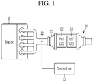
- FIG. 1 is a schematic configuration diagram of an exhaust gas purification system for vehicle according to an exemplary embodiment of the present disclosure.
- an exhaust gas purification system 20 for vehicle is provided on an exhaust pipe 12 connected to an exhaust side of an engine 10 for purifying an exhaust gas of the engine 10, and includes a housing 21 disposed on the exhaust pipe 12, a front end catalyst 22 and a rear end catalyst 24 incorporated in the housing 21, and a controller 25 to control the concentration of unburned fuel contained in the exhaust gas flowing into the housing 21.
- a part of the housing 21 is cut to show the configuration of the front end catalyst 22 and the rear end catalyst 24.
- the engine 10 burns air/fuel mixture in which fuel and air are mixed so as to convert chemical energy into mechanical energy.
- the engine 10 includes a plurality of combustion chambers for generating a driving force by combustion of fuel, and is connected to an intake manifold so as to receive the air in a combustion chamber, and is connected to an exhaust manifold such that exhaust gas generated in combustion process is gathered in the exhaust manifold and is exhausted to the exterior.
- An injector is mounted in the combustion chamber so as to inject the fuel into the combustion chamber.
- the exhaust pipe 12 is connected to the exhaust side of the engine 10 to exhaust the exhaust gas discharged from the engine 10 to the outside.
- the exhaust pipe 12 may extend rearward along the under floor of the vehicle to exhaust the exhaust gas to the rear of the vehicle, and the arrangement of the exhaust pipe 12 and the connection with the exhaust side of the engine 10 will be apparent to those skilled in the art (hereinafter, those skilled in the art), so that detailed description thereof will be omitted.
- the exhaust gas discharged from the engine 10 passes through the exhaust pipe 12 and passes through the exhaust gas purification system 20. Further, the exhaust gas passing through the exhaust gas purification system 20 passes through the front end catalyst 22 and the rear end catalyst 24 in sequence. That is, the front end of the housing 21 is connected to the engine 10 by the exhaust pipe 12 so as to receive the exhaust gas discharged from the engine 10, and the rear end of the housing 21 is connected to the exhaust gas purification system 20 so as to discharge the exhaust gas passed through the exhaust pipe 12 rearward of the vehicle.
- the front end and the rear end of the component refer to the flow of the exhaust gas
- the exhaust gas is defined as flowing from the front end to the rear end of the component.
- the front end catalyst 22 functions to primarily purify the exhaust gas flowing into the housing 21 through the front end of the housing 21.
- the front end catalyst may be a palladium (Pd) catalyst that oxidizes hydrocarbons (HC) and carbon monoxide (CO) and occludes nitrogen oxides (NOx). More particularly, the front end catalyst may be a Pd/CZO catalyst in the palladium (Pd) catalyst.
- the rear end catalyst 24 functions to secondarily purify the exhaust gas passing through the front end catalyst 22 before the exhaust gas flows out to the rear end of the housing 21.
- the rear end catalyst 24 may be a rhodium (Rh) catalyst for reducing nitrogen oxides. More particularly, the rear end catalyst may be an Rh/CZO catalyst in the rhodium (Rh) catalyst.
- the controller 25 is connected to the exhaust pipe 12 at the front end of the housing 21 to control the concentration of the unburned fuel contained in the exhaust gas flowing into the housing 21.
- the controller 25 detects the temperature of the exhaust gas flowing through the exhaust pipe 12 connected to the front end of the housing 21 through the temperature sensor connected to the controller 25, and collects information of the air-fuel ratio ( ⁇ ) by the oxygen sensor connected to the controller 25.
- the controller 25 may perform the lean control so that the concentration of the unburned fuel contained in the exhaust gas flowing into the housing after starting the engine becomes fuel lean.
- the lean control can be performed under the condition that the air-fuel ratio ( ⁇ ) is about 1.05.
- the controller 25 terminates the lean control at a set temperature according to the degree of deterioration of the front end catalyst 22 and the rear end catalyst 24.
- the lean control proceeds to a temperature at which the front end catalyst 22 and the rear end catalyst 24 are activated, and the activated temperature is lower for new products with lower degrees of deterioration of the front end catalyst 22 and the rear end catalyst 24 and the higher the activation temperature is for an older product (deteriorated product) having a higher degree of deterioration of the front end catalyst 22 and the rear end catalyst 24.
- the controller 25 terminates the lean control if the front end catalyst 22 and the rear end catalyst 24 are new ones. Further, the controller 25 terminates the lean control when the temperature of the exhaust gas flowing into the housing 21 reaches the activation temperature (set temperature) of about 400°C corresponding to a maximum oxygen storage capacity in case of deteriorated products if the front end catalyst 22 and the rear end catalyst 24 are deteriorated products.
- the controller 25 performs normal control to control the concentration of the unburned fuel contained in the exhaust gas flowing into the housing 21 such that the fuel lean and the fuel rich periodically repeat the regular alternation after termination of lean control.
- the controller 25 controls the oxygen purge to be performed before performing the normal control if the front end catalyst 22 and the rear end catalyst 24 are degraded products.
- the front end catalyst 22 and the rear end catalyst 24 are new, no separate oxygen purge is required since the catalysts 22 and 24 are activated and nitrogen oxides (NOx) can be desorbed and reduced before an oxygen storage capacity (OSC) material of the catalysts 22 and 24 is saturated with oxygen.
- OSC oxygen storage capacity
- the front end catalyst 22 and the rear end catalyst 24 are deteriorated products, at a temperature at which the catalysts 22 and 24 are activated, the OSC material of the catalysts 22 and 24 is saturated with oxygen, and nitrogen oxides (NOx) are difficult to desorb and reduce.
- the controller 25 performs oxygen purge first before performing the normal control to control the oxygen saturation in the OSC material of the catalyst 22 and 24 to be less than about 40%.
- the oxygen purge may be performed for about 3 seconds or more under the rich condition of the air-fuel ratio ( ⁇ ) of about 0.95 or less.
- FIG. 2 is a graph showing nitrogen storage performance in the case where the exhaust gas purification system for a vehicle according to an exemplary embodiment of the present disclosure performs lean control in the cold state of the engine and terminates lean control before and after oxygen saturation of the OSC material of the catalyst
- FIG. 3 is a graph showing the change of air-fuel ratio ( ⁇ ) in each case where the exhaust gas purification system for a vehicle according to an exemplary embodiment of the present disclosure performs lean control in the cold state of the engine and terminates lean control before and after oxygen saturation of the OSC material of the catalyst.
- the vertical axis represents the concentration of nitrogen oxides (NOx) contained in the exhaust gas
- the horizontal axis represents time. That is, the graph shows the concentration of nitrogen oxides (NOx) contained in the exhaust gas according to the passage of time in the initial cold state after the start of the engine 10.
- a catalyst temperature rise curve along with the passage of time in the initial cold state after the start of the engine 10 is shown together with a two-dot chain line
- the change in the concentration of nitrogen oxides (NOx) contained in the exhaust gas flowing out of the housing 21 is shown by thick and thin solid lines, respectively when the lean control before and after the oxygen saturation in the OSC material of the catalysts 22 and 24 is terminated (case 1, case 2).
- FIG. 3 shows the change of air-fuel ratio ( ⁇ ) of the case where the lean control is terminated (case 1, case 2) before and after oxygen in the OSC material of the catalysts 22 and 24 and performs normal control along with time flow in the initial cold state after the start of the engine 10.
- FIG. 4 is a graph showing the oxygen saturation of the OSC material of the catalyst in each case where the lean control according to the degree of deterioration of the catalyst is completed in the cold state of the engine of the exhaust gas purification system for a vehicle according to an exemplary embodiment of the present disclosure
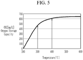
- FIG. 5 is a graph showing the lean control termination temperature in each case according to the degree of deterioration of the catalyst in the cold state of the engine of the exhaust gas purification system for a vehicle according to an exemplary embodiment of the present disclosure.
- the catalyst activation temperature corresponding to a maximum oxygen storage capacity is about 300°C, and the lean burn is terminated at point A (case 1). Then, after the temperature rises, the oxygen storage capacity in the OSC material of the catalysts 22 and 24 becomes the capacity corresponding to the point B, which is different from the maximum oxygen storage capacity. Therefore, in this case, the nitrogen oxide (NOx) desorbing performance can be maintained high even after proceeding to normal combustion immediately after completion of the lean burn without the need for oxygen purging of the catalysts 22 and 24 separately.
- NOx nitrogen oxide
- the catalyst activation temperature corresponding to a maximum oxygen storage capacity is about 400°C, and the lean burn is terminated at the point C (case 2). Then, after the temperature rises, the oxygen storage capacity in the OSC material is not significantly different from the maximum oxygen storage capacity, so that the oxygen saturation is very high. Therefore, in this case, it is necessary to lower oxygen saturation to the point D through oxygen purging separately. At this time, the oxygen saturation in the OSC material of the catalysts 22 and 24 may be reduced to about 40% or less and the oxygen purge may be performed for about 3 seconds or more under the rich condition of about 0.95 or less. After the oxygen purge is terminated, the normal combustion is advanced to maintain the nitrogen oxide (NOx) desorption performance high.
- NOx nitrogen oxide
- FIG. 6 is a flowchart illustrating a method of controlling an exhaust gas purification system for a vehicle according to an exemplary embodiment of the present disclosure.
- the exhaust gas purification system for vehicle includes a housing 21 disposed on the exhaust pipe 12 so as to receive the exhaust gas discharged from the engine 10 and to exhaust the exhaust gas passed rearward, a front end catalyst 22 primarily purifying the exhaust gas, a rear end catalyst 24 secondarily purifying the exhaust gas passing through the front end catalyst 22, and a controller 25 connected to the exhaust pipe 12 at a front end of the housing 21 to control the concentration of unburned fuel contained in the exhaust gas flowing into the housing 21.
- the method firstly includes starting the engine 10 S101.
- lean control is performed to control the concentration of the unburned fuel contained in the exhaust gas flowing into the housing 21 to be fuel lean by the controller 25 S102.
- the lean control may be such that the minimum air-fuel ratio lambda is maintained at 1.03 or more, and the air-fuel ratio lambda may be maintained at about 1.05.
- the first set temperature is 300°C which is a catalyst activation temperature.
- the lean control is terminated if the temperatures of the front end catalyst 22 and the rear end catalyst 24 are equal to or higher than the first set temperature S105, and normal control is performed to control the concentration of the unburned fuel contained in the exhaust gas flowing into the housing 21 such that the fuel lean and the fuel rich periodically repeat the regular alternation S106.
- the second set temperature may be about 400°C which is a catalyst activation temperature.
- the lean control is terminated if the temperatures of the front end catalyst 22 and the rear end catalyst 24 are equal to or higher than the second set temperature S108, and oxygen purge is performed on the front end catalyst 22 and the rear end catalyst 24 S109.
- the oxygen purge may be performed to control the oxygen saturation in the OSC material of the front end catalyst 22 and the rear end catalyst 24 to less than about 40%, and performed for 3 seconds or more under the rich condition of the air-fuel ratio ( ⁇ ) of about 0.95 or less.
- normal control is performed to control the concentration of the unburned fuel contained in the exhaust gas flowing into the housing 21 such that the fuel lean and the fuel rich periodically repeat the regular alternation S106.
- the nitrogen oxides in the exhaust gas are effectively removed by switching to the normal operation mode in which the fuel lean and fuel rich conditions are alternately performed in consideration of the OSC characteristic.
Landscapes
- Engineering & Computer Science (AREA)
- Chemical & Material Sciences (AREA)
- Combustion & Propulsion (AREA)
- Mechanical Engineering (AREA)
- General Engineering & Computer Science (AREA)
- Chemical Kinetics & Catalysis (AREA)
- Materials Engineering (AREA)
- Organic Chemistry (AREA)
- Health & Medical Sciences (AREA)
- Biomedical Technology (AREA)
- Environmental & Geological Engineering (AREA)
- Analytical Chemistry (AREA)
- General Chemical & Material Sciences (AREA)
- Oil, Petroleum & Natural Gas (AREA)
- Toxicology (AREA)
- Exhaust Gas After Treatment (AREA)
Claims (10)
- Abgasreinigungssystem für ein Fahrzeug, das an einem Abgasrohr angeordnet ist, das mit einer Abgasseite eines Verbrennungsmotors verbunden ist, zum Reinigen eines Abgases des Verbrennungsmotors (10), wobei das System aufweist:ein Gehäuse (21), das an dem Abgasrohr (12) angeordnet ist, um das aus dem Verbrennungsmotor ausgegebene Abgas aufzunehmen und das nach hinten geleitete Abgas auszustoßen,einen vorderes-Ende-Katalysator (22), der in dem Gehäuse angeordnet ist, um das Abgas, das durch ein vorderes Ende des Gehäuses in das Gehäuse strömt, primär zu reinigen,einen hinteres-Ende-Katalysator (24), der in dem Gehäuse angeordnet ist, um das Abgas, das durch den vorderes-Ende-Katalysator hindurchtritt, sekundär zu reinigen, bevor das Abgas zu einem hinteren Ende des Gehäuses ausströmt, undeine Steuereinrichtung (25), die mit dem Abgasrohr an einem vorderen Ende des Gehäuses verbunden ist, um eine Konzentration von unverbranntem Kraftstoff zu steuern, der in dem Abgas enthalten ist, das in das Gehäuse strömt,wobei die Steuereinrichtung konfiguriert ist, um:eine Magersteuerung durchzuführen, um die Konzentration des unverbrannten Kraftstoffs, der in dem Abgas enthalten ist, das in das Gehäuse strömt, zu steuern, um nach dem Starten des Verbrennungsmotors kraftstoffmager zu sein,die Magersteuerung bei einer eingestellten Temperatur zu beenden, entsprechend einer maximalen Sauerstoffspeicherkapazität, gemäß einem Grad der Verschlechterung des vorderes-Ende-Katalysators und des hinteres-Ende-Katalysators,eine Normalsteuerung durchzuführen, um die Konzentration des unverbrannten Kraftstoffs, der in dem Abgas enthalten ist, das in das Gehäuse strömt, zu steuern, so dass sich eine kraftstoffmagere Bedingung und eine kraftstoffreiche Bedingung periodisch abwechselnd wiederholen,die Magersteuerung zu beenden, wenn der vorderes-Ende-Katalysator und der hinteres-Ende-Katalysator verschlechterte Produkte sind, wenn die Temperatur des Abgases, das in das Gehäuse strömt, 400°C erreicht, entsprechend einer maximalen Sauerstoffspeicherkapazität im Fall von verschlechterten Produkten,eine Sauerstoffspülung am vorderes-Ende-Katalysator und am hinters-Ende-Katalysator durchzuführen, nachdem die Magersteuerung beendet ist, bevor die Normalsteuerung durchgeführt wird, unddie Sauerstoffspülung durchführen, um die Sauerstoffsättigung im OSC-Material des vorderes-Ende-Katalysators und des hinteres-Ende-Katalysators auf weniger als 40% zu steuern.
- System gemäß Anspruch 1, wobei der vorderes-Ende-Katalysator ein Palladiumkatalysator ist, der Kohlenwasserstoffe und Kohlenstoffmonoxid oxidiert und Stickstoffoxide einschließt.
- System gemäß Anspruch 2, wobei der vorderes-Ende-Katalysator ein Pd/CeO2-ZrO2-Katalysator ist.
- System gemäß irgendeinem der Ansprüche 1 bis 3, wobei der hinteres-Ende-Katalysator ein Rhodiumkatalysator zum Reduzieren von Stickstoffoxiden ist.
- System gemäß Anspruch 4, wobei der hinteres-Ende-Katalysator ein Rh/CeO2-ZrO2-Katalysator ist.
- System gemäß irgendeinem der Ansprüche 1 bis 5, wobei die Steuereinrichtung die Magersteuerung beendet, wenn der vorderes-Ende-Katalysator und der hinteres-Ende-Katalysator neue Produkte sind, wenn eine Temperatur des Abgases, das in das Gehäuse strömt, 300°C erreicht, entsprechend einer maximalen Sauerstoffspeicherkapazität im Fall von neuen Produkten.
- System gemäß Anspruch 1, wobei die Steuereinrichtung die Sauerstoffspülung für 3 Sekunden oder mehr unter der kraftstoffreichen Bedingung eines Luft-Kraftstoff-Verhältnisses von 0,95 oder weniger durchführt.
- Verfahren zum Steuern eines Abgasreinigungssystems für ein Fahrzeug, das aufweist ein Gehäuse (21), das an einem Abgasrohr (12) angeordnet ist, um ein aus einem Verbrennungsmotor (10) ausgegebenes Abgas aufzunehmen und das nach hinten geleitete Abgas auszustoßen, einen vorderes-Ende-Katalysator (22), der das Abgas primär reinigt, einen hinteres-Ende-Katalysator (24), der das durch den vorderes-Ende-Katalysators hindurchtretende Abgas sekundär reinigt, und eine Steuereinrichtung (25), die mit dem Abgasrohr an einem vorderen Ende des Gehäuses verbunden ist, um eine Konzentration von unverbranntem Kraftstoff zu steuern, der in dem Abgas enthalten ist, das in das Gehäuse strömt, wobei das Verfahren aufweist:Starten des Verbrennungsmotors,Durchführen einer Magersteuerung, um die Konzentration des unverbrannten Kraftstoffs, der in dem Abgas enthalten ist, das in das Gehäuse strömt, zu steuern, um kraftstoffmager zu sein,Ermitteln, ob der vorderes-Ende-Katalysator und der hinteres-Ende-Katalysator neue oder verschlechterte Produkte sind,Ermitteln, ob Temperaturen des vorderes-Ende-Katalysators bzw. des hinteres-Ende-Katalysators gleich oder höher als eine erste eingestellte Temperatur sind, entsprechend einer maximalen Sauerstoffspeicherkapazität im Fall von neuen Produkten, wenn der vorderes-Ende-Katalysator und der hinteres-Ende-Katalysator neue Produkte sind,Beenden der Magersteuerung, wenn die Temperaturen des vorderes-Ende-Katalysators bzw. des hinteres-Ende-Katalysators gleich oder höher als die erste eingestellte Temperatur sind,Durchführen einer Normalsteuerung, um die Konzentration des unverbrannten Kraftstoffs, der in dem Abgas enthalten ist, das in das Gehäuse strömt, so zu steuern, dass sich eine kraftstoffmagere Bedingung und eine kraftstoffreiche Bedingung periodisch abwechselnd wiederholen,nach dem Ermitteln, ob der vorderes-Ende-Katalysator und der hinteres-Ende-Katalysator neue oder verschlechterte Produkte sind:Ermitteln, ob die Temperaturen des vorderes-Ende-Katalysators bzw. des hinteres-Ende-Katalysators gleich oder höher als eine zweite eingestellte Temperatur sind, entsprechend einer maximalen Sauerstoffspeicherkapazität im Fall von verschlechterten Produkten, wenn der vorderes-Ende-Katalysator und der hinteres-Ende-Katalysator verschlechterte Produkte sind,Beenden der Magersteuerung, wenn die Temperaturen des vorderes-Ende-Katalysators bzw. des hinteres-Ende-Katalysators gleich oder höher als die zweite eingestellte Temperatur sind, undDurchführen einer Sauerstoffspülung an dem vorderes-Ende-Katalysator und dem hinteres-Ende-Katalysator,wobei die zweite eingestellte Temperatur 400°C beträgt undwobei die Sauerstoffspülung durchgeführt wird, um eine Sauerstoffsättigung in einem Sauerstoffspeicherkapazitätsmaterial des vorderes-Ende-Katalysators und des hinteres-Ende-Katalysators auf weniger als 40% zu steuern.
- Verfahren gemäß Anspruch 8, wobei die erste eingestellte Temperatur 300°C beträgt.
- Verfahren gemäß Anspruch 8 oder 9, wobei die Sauerstoffspülung für 3 Sekunden oder mehr unter der kraftstoffreichen Bedingung eines Luft-Kraftstoff-Verhältnisses von 0,95 oder weniger durchgeführt wird.
Applications Claiming Priority (1)
| Application Number | Priority Date | Filing Date | Title |
|---|---|---|---|
| KR1020190020389A KR102654452B1 (ko) | 2019-02-21 | 2019-02-21 | 자동차의 배기가스 정화장치 및 그 제어방법 |
Publications (3)
| Publication Number | Publication Date |
|---|---|
| EP3699408A1 EP3699408A1 (de) | 2020-08-26 |
| EP3699408B1 true EP3699408B1 (de) | 2021-06-30 |
| EP3699408B8 EP3699408B8 (de) | 2021-08-11 |
Family
ID=67659412
Family Applications (1)
| Application Number | Title | Priority Date | Filing Date |
|---|---|---|---|
| EP19192482.8A Active EP3699408B8 (de) | 2019-02-21 | 2019-08-20 | Abgasreinigungssystem für fahrzeug und verfahren zu dessen steuerung |
Country Status (3)
| Country | Link |
|---|---|
| US (1) | US11125173B2 (de) |
| EP (1) | EP3699408B8 (de) |
| KR (1) | KR102654452B1 (de) |
Families Citing this family (5)
| Publication number | Priority date | Publication date | Assignee | Title |
|---|---|---|---|---|
| DE102017115408A1 (de) * | 2017-07-10 | 2019-01-10 | Volkswagen Aktiengesellschaft | Abgasnachbehandlungssystem und Verfahren zur Abgasnachbehandlung eines Verbrennungsmotors |
| JP7171751B2 (ja) * | 2018-09-28 | 2022-11-15 | ユミコア日本触媒株式会社 | 排ガス浄化触媒、排ガスの浄化方法、及び排ガス浄化触媒の製造方法 |
| CN113803136B (zh) * | 2020-06-12 | 2023-02-03 | 丰田自动车株式会社 | 内燃机的排气净化装置及催化剂 |
| JP7444104B2 (ja) * | 2021-02-24 | 2024-03-06 | トヨタ自動車株式会社 | 内燃機関の制御装置 |
| CN118030252A (zh) * | 2021-09-30 | 2024-05-14 | 宁波吉利罗佑发动机零部件有限公司 | 用于发动机排气净化处理的三效催化转化系统及其应用 |
Family Cites Families (6)
| Publication number | Priority date | Publication date | Assignee | Title |
|---|---|---|---|---|
| US6539706B2 (en) * | 2001-06-19 | 2003-04-01 | Ford Global Technologies, Inc. | Method and system for preconditioning an emission control device for operation about stoichiometry |
| DE102004029202A1 (de) * | 2004-01-02 | 2005-07-28 | Volkswagen Ag | Abgasreinigungssystem mit Haupt- und Sekundärspeichereinrichtung für Stickoxide |
| US20040168431A1 (en) * | 2004-01-13 | 2004-09-02 | Goralski Christian T. | System and method to minimize the amount of NOx emissions by optimizing the amount of supplied reductant |
| JP2009191823A (ja) * | 2008-02-18 | 2009-08-27 | Toyota Central R&D Labs Inc | NOx浄化装置 |
| US8100107B2 (en) * | 2010-07-21 | 2012-01-24 | Ford Global Technologies, Llc | Method and system for engine control |
| JP6597101B2 (ja) * | 2015-09-16 | 2019-10-30 | 三菱自動車工業株式会社 | 排気浄化制御装置 |
-
2019
- 2019-02-21 KR KR1020190020389A patent/KR102654452B1/ko active Active
- 2019-08-20 EP EP19192482.8A patent/EP3699408B8/de active Active
- 2019-08-26 US US16/550,732 patent/US11125173B2/en active Active
Non-Patent Citations (1)
| Title |
|---|
| None * |
Also Published As
| Publication number | Publication date |
|---|---|
| US11125173B2 (en) | 2021-09-21 |
| US20200271067A1 (en) | 2020-08-27 |
| KR102654452B1 (ko) | 2024-04-03 |
| EP3699408B8 (de) | 2021-08-11 |
| EP3699408A1 (de) | 2020-08-26 |
| KR20200102150A (ko) | 2020-08-31 |
Similar Documents
| Publication | Publication Date | Title |
|---|---|---|
| EP3699408B1 (de) | Abgasreinigungssystem für fahrzeug und verfahren zu dessen steuerung | |
| US9587540B2 (en) | Method and device for reactivating exhaust-gas purification systems of diesel engines with low-pressure EGR | |
| RU2617770C2 (ru) | Автомобильная система дополнительной каталитической обработки | |
| US8528321B2 (en) | Exhaust purification system for internal combustion engine and desulfurization method for the same | |
| AU2009247433B2 (en) | System for exhaust gas purification and method of controlling the same | |
| US20050153828A1 (en) | Exhaust gas decontamination system and method of controlling the same | |
| WO2002066813A1 (en) | Fuel injection control method for diesel engine and regenerative control method for exhaust gas after treatment device | |
| JP3201237B2 (ja) | 内燃機関の排気浄化装置 | |
| KR20030071756A (ko) | 배기시스템을 가진 린번 가솔린 엔진 | |
| US11859526B2 (en) | Exhaust gas purification system for a gasoline engine | |
| US8240139B2 (en) | Method for purifying nitrogen oxide in exhaust gas and exhaust system operating the same | |
| EP3639921B1 (de) | Abgasreinigungssystem für einen benzinmotor | |
| JP2013522517A (ja) | 排気ガス制御の改善 | |
| US10697340B1 (en) | After treatment system and after treatment method for lean-burn engine | |
| WO2020079137A1 (en) | Exhaust gas purification system for a gasoline engine | |
| WO2020079140A1 (en) | Exhaust gas purification system for a gasoline engine | |
| WO2007058015A1 (ja) | 排気ガス浄化システムの再生制御方法及び排気ガス浄化システム | |
| CN1350614A (zh) | 具有NOx存储催化器和前置催化器的尾气净化方法和尾气净化装置 | |
| KR102750538B1 (ko) | 배기가스 후처리 장치 | |
| KR102715804B1 (ko) | 자동차의 배기가스 정화장치 및 그 제어방법 | |
| KR102598405B1 (ko) | 자동차의 배기가스 정화장치 및 그 제어방법 | |
| US11499465B2 (en) | Exhaust gas purification system for vehicle | |
| KR101040346B1 (ko) | 디젤차량의 후처리장치 및 그것의 2차 분사 제어방법 | |
| CN101006252A (zh) | 包括NOx吸收剂的排气系统中的还原剂的添加 | |
| KR20210154313A (ko) | 배기가스 정화장치 및 그 제어 방법 |
Legal Events
| Date | Code | Title | Description |
|---|---|---|---|
| PUAI | Public reference made under article 153(3) epc to a published international application that has entered the european phase |
Free format text: ORIGINAL CODE: 0009012 |
|
| STAA | Information on the status of an ep patent application or granted ep patent |
Free format text: STATUS: REQUEST FOR EXAMINATION WAS MADE |
|
| 17P | Request for examination filed |
Effective date: 20200710 |
|
| AK | Designated contracting states |
Kind code of ref document: A1 Designated state(s): AL AT BE BG CH CY CZ DE DK EE ES FI FR GB GR HR HU IE IS IT LI LT LU LV MC MK MT NL NO PL PT RO RS SE SI SK SM TR |
|
| AX | Request for extension of the european patent |
Extension state: BA ME |
|
| RIC1 | Information provided on ipc code assigned before grant |
Ipc: F02D 41/02 20060101ALI20200908BHEP Ipc: F02D 41/00 20060101ALI20200908BHEP Ipc: F01N 3/10 20060101ALI20200908BHEP Ipc: F02D 41/14 20060101ALI20200908BHEP Ipc: F01N 3/08 20060101AFI20200908BHEP Ipc: F01N 13/00 20100101ALI20200908BHEP Ipc: F01N 9/00 20060101ALI20200908BHEP |
|
| GRAP | Despatch of communication of intention to grant a patent |
Free format text: ORIGINAL CODE: EPIDOSNIGR1 |
|
| STAA | Information on the status of an ep patent application or granted ep patent |
Free format text: STATUS: GRANT OF PATENT IS INTENDED |
|
| INTG | Intention to grant announced |
Effective date: 20201124 |
|
| GRAS | Grant fee paid |
Free format text: ORIGINAL CODE: EPIDOSNIGR3 |
|
| GRAA | (expected) grant |
Free format text: ORIGINAL CODE: 0009210 |
|
| STAA | Information on the status of an ep patent application or granted ep patent |
Free format text: STATUS: THE PATENT HAS BEEN GRANTED |
|
| AK | Designated contracting states |
Kind code of ref document: B1 Designated state(s): AL AT BE BG CH CY CZ DE DK EE ES FI FR GB GR HR HU IE IS IT LI LT LU LV MC MK MT NL NO PL PT RO RS SE SI SK SM TR |
|
| REG | Reference to a national code |
Ref country code: CH Ref legal event code: EP |
|
| REG | Reference to a national code |
Ref country code: AT Ref legal event code: REF Ref document number: 1406540 Country of ref document: AT Kind code of ref document: T Effective date: 20210715 |
|
| REG | Reference to a national code |
Ref country code: DE Ref legal event code: R081 Ref document number: 602019005716 Country of ref document: DE Owner name: KIA CORPORATION, KR Free format text: FORMER OWNERS: HYUNDAI MOTOR COMPANY, SEOUL, KR; KIA MOTORS CORPORATION, SEOUL, KR Ref country code: DE Ref legal event code: R081 Ref document number: 602019005716 Country of ref document: DE Owner name: HYUNDAI MOTOR COMPANY, KR Free format text: FORMER OWNERS: HYUNDAI MOTOR COMPANY, SEOUL, KR; KIA MOTORS CORPORATION, SEOUL, KR Ref country code: DE Ref legal event code: R082 Ref document number: 602019005716 Country of ref document: DE Representative=s name: VIERING, JENTSCHURA & PARTNER MBB PATENT- UND , DE |
|
| REG | Reference to a national code |
Ref country code: DE Ref legal event code: R096 Ref document number: 602019005716 Country of ref document: DE |
|
| RAP4 | Party data changed (patent owner data changed or rights of a patent transferred) |
Owner name: HYUNDAI MOTOR COMPANY Owner name: KIA CORPORATION |
|
| REG | Reference to a national code |
Ref country code: IE Ref legal event code: FG4D |
|
| REG | Reference to a national code |
Ref country code: LT Ref legal event code: MG9D |
|
| PG25 | Lapsed in a contracting state [announced via postgrant information from national office to epo] |
Ref country code: BG Free format text: LAPSE BECAUSE OF FAILURE TO SUBMIT A TRANSLATION OF THE DESCRIPTION OR TO PAY THE FEE WITHIN THE PRESCRIBED TIME-LIMIT Effective date: 20210930 Ref country code: HR Free format text: LAPSE BECAUSE OF FAILURE TO SUBMIT A TRANSLATION OF THE DESCRIPTION OR TO PAY THE FEE WITHIN THE PRESCRIBED TIME-LIMIT Effective date: 20210630 Ref country code: FI Free format text: LAPSE BECAUSE OF FAILURE TO SUBMIT A TRANSLATION OF THE DESCRIPTION OR TO PAY THE FEE WITHIN THE PRESCRIBED TIME-LIMIT Effective date: 20210630 |
|
| REG | Reference to a national code |
Ref country code: NL Ref legal event code: MP Effective date: 20210630 |
|
| REG | Reference to a national code |
Ref country code: AT Ref legal event code: MK05 Ref document number: 1406540 Country of ref document: AT Kind code of ref document: T Effective date: 20210630 |
|
| PG25 | Lapsed in a contracting state [announced via postgrant information from national office to epo] |
Ref country code: GR Free format text: LAPSE BECAUSE OF FAILURE TO SUBMIT A TRANSLATION OF THE DESCRIPTION OR TO PAY THE FEE WITHIN THE PRESCRIBED TIME-LIMIT Effective date: 20211001 Ref country code: NO Free format text: LAPSE BECAUSE OF FAILURE TO SUBMIT A TRANSLATION OF THE DESCRIPTION OR TO PAY THE FEE WITHIN THE PRESCRIBED TIME-LIMIT Effective date: 20210930 Ref country code: LV Free format text: LAPSE BECAUSE OF FAILURE TO SUBMIT A TRANSLATION OF THE DESCRIPTION OR TO PAY THE FEE WITHIN THE PRESCRIBED TIME-LIMIT Effective date: 20210630 Ref country code: RS Free format text: LAPSE BECAUSE OF FAILURE TO SUBMIT A TRANSLATION OF THE DESCRIPTION OR TO PAY THE FEE WITHIN THE PRESCRIBED TIME-LIMIT Effective date: 20210630 Ref country code: SE Free format text: LAPSE BECAUSE OF FAILURE TO SUBMIT A TRANSLATION OF THE DESCRIPTION OR TO PAY THE FEE WITHIN THE PRESCRIBED TIME-LIMIT Effective date: 20210630 |
|
| PG25 | Lapsed in a contracting state [announced via postgrant information from national office to epo] |
Ref country code: SM Free format text: LAPSE BECAUSE OF FAILURE TO SUBMIT A TRANSLATION OF THE DESCRIPTION OR TO PAY THE FEE WITHIN THE PRESCRIBED TIME-LIMIT Effective date: 20210630 Ref country code: NL Free format text: LAPSE BECAUSE OF FAILURE TO SUBMIT A TRANSLATION OF THE DESCRIPTION OR TO PAY THE FEE WITHIN THE PRESCRIBED TIME-LIMIT Effective date: 20210630 Ref country code: RO Free format text: LAPSE BECAUSE OF FAILURE TO SUBMIT A TRANSLATION OF THE DESCRIPTION OR TO PAY THE FEE WITHIN THE PRESCRIBED TIME-LIMIT Effective date: 20210630 Ref country code: PT Free format text: LAPSE BECAUSE OF FAILURE TO SUBMIT A TRANSLATION OF THE DESCRIPTION OR TO PAY THE FEE WITHIN THE PRESCRIBED TIME-LIMIT Effective date: 20211102 Ref country code: CZ Free format text: LAPSE BECAUSE OF FAILURE TO SUBMIT A TRANSLATION OF THE DESCRIPTION OR TO PAY THE FEE WITHIN THE PRESCRIBED TIME-LIMIT Effective date: 20210630 Ref country code: AT Free format text: LAPSE BECAUSE OF FAILURE TO SUBMIT A TRANSLATION OF THE DESCRIPTION OR TO PAY THE FEE WITHIN THE PRESCRIBED TIME-LIMIT Effective date: 20210630 Ref country code: SK Free format text: LAPSE BECAUSE OF FAILURE TO SUBMIT A TRANSLATION OF THE DESCRIPTION OR TO PAY THE FEE WITHIN THE PRESCRIBED TIME-LIMIT Effective date: 20210630 Ref country code: EE Free format text: LAPSE BECAUSE OF FAILURE TO SUBMIT A TRANSLATION OF THE DESCRIPTION OR TO PAY THE FEE WITHIN THE PRESCRIBED TIME-LIMIT Effective date: 20210630 Ref country code: ES Free format text: LAPSE BECAUSE OF FAILURE TO SUBMIT A TRANSLATION OF THE DESCRIPTION OR TO PAY THE FEE WITHIN THE PRESCRIBED TIME-LIMIT Effective date: 20210630 |
|
| PG25 | Lapsed in a contracting state [announced via postgrant information from national office to epo] |
Ref country code: PL Free format text: LAPSE BECAUSE OF FAILURE TO SUBMIT A TRANSLATION OF THE DESCRIPTION OR TO PAY THE FEE WITHIN THE PRESCRIBED TIME-LIMIT Effective date: 20210630 |
|
| REG | Reference to a national code |
Ref country code: DE Ref legal event code: R097 Ref document number: 602019005716 Country of ref document: DE |
|
| PG25 | Lapsed in a contracting state [announced via postgrant information from national office to epo] |
Ref country code: MC Free format text: LAPSE BECAUSE OF FAILURE TO SUBMIT A TRANSLATION OF THE DESCRIPTION OR TO PAY THE FEE WITHIN THE PRESCRIBED TIME-LIMIT Effective date: 20210630 |
|
| REG | Reference to a national code |
Ref country code: BE Ref legal event code: MM Effective date: 20210831 |
|
| PG25 | Lapsed in a contracting state [announced via postgrant information from national office to epo] |
Ref country code: DK Free format text: LAPSE BECAUSE OF FAILURE TO SUBMIT A TRANSLATION OF THE DESCRIPTION OR TO PAY THE FEE WITHIN THE PRESCRIBED TIME-LIMIT Effective date: 20210630 |
|
| PLBE | No opposition filed within time limit |
Free format text: ORIGINAL CODE: 0009261 |
|
| STAA | Information on the status of an ep patent application or granted ep patent |
Free format text: STATUS: NO OPPOSITION FILED WITHIN TIME LIMIT |
|
| PG25 | Lapsed in a contracting state [announced via postgrant information from national office to epo] |
Ref country code: LU Free format text: LAPSE BECAUSE OF NON-PAYMENT OF DUE FEES Effective date: 20210820 Ref country code: AL Free format text: LAPSE BECAUSE OF FAILURE TO SUBMIT A TRANSLATION OF THE DESCRIPTION OR TO PAY THE FEE WITHIN THE PRESCRIBED TIME-LIMIT Effective date: 20210630 |
|
| 26N | No opposition filed |
Effective date: 20220331 |
|
| PG25 | Lapsed in a contracting state [announced via postgrant information from national office to epo] |
Ref country code: IT Free format text: LAPSE BECAUSE OF FAILURE TO SUBMIT A TRANSLATION OF THE DESCRIPTION OR TO PAY THE FEE WITHIN THE PRESCRIBED TIME-LIMIT Effective date: 20210630 Ref country code: IE Free format text: LAPSE BECAUSE OF NON-PAYMENT OF DUE FEES Effective date: 20210820 Ref country code: BE Free format text: LAPSE BECAUSE OF NON-PAYMENT OF DUE FEES Effective date: 20210831 |
|
| REG | Reference to a national code |
Ref country code: CH Ref legal event code: PL |
|
| PG25 | Lapsed in a contracting state [announced via postgrant information from national office to epo] |
Ref country code: LT Free format text: LAPSE BECAUSE OF FAILURE TO SUBMIT A TRANSLATION OF THE DESCRIPTION OR TO PAY THE FEE WITHIN THE PRESCRIBED TIME-LIMIT Effective date: 20210630 Ref country code: LI Free format text: LAPSE BECAUSE OF NON-PAYMENT OF DUE FEES Effective date: 20220831 Ref country code: CH Free format text: LAPSE BECAUSE OF NON-PAYMENT OF DUE FEES Effective date: 20220831 |
|
| PG25 | Lapsed in a contracting state [announced via postgrant information from national office to epo] |
Ref country code: CY Free format text: LAPSE BECAUSE OF FAILURE TO SUBMIT A TRANSLATION OF THE DESCRIPTION OR TO PAY THE FEE WITHIN THE PRESCRIBED TIME-LIMIT Effective date: 20210630 |
|
| P01 | Opt-out of the competence of the unified patent court (upc) registered |
Effective date: 20230530 |
|
| PG25 | Lapsed in a contracting state [announced via postgrant information from national office to epo] |
Ref country code: HU Free format text: LAPSE BECAUSE OF FAILURE TO SUBMIT A TRANSLATION OF THE DESCRIPTION OR TO PAY THE FEE WITHIN THE PRESCRIBED TIME-LIMIT; INVALID AB INITIO Effective date: 20190820 |
|
| PG25 | Lapsed in a contracting state [announced via postgrant information from national office to epo] |
Ref country code: MK Free format text: LAPSE BECAUSE OF FAILURE TO SUBMIT A TRANSLATION OF THE DESCRIPTION OR TO PAY THE FEE WITHIN THE PRESCRIBED TIME-LIMIT Effective date: 20210630 |
|
| PG25 | Lapsed in a contracting state [announced via postgrant information from national office to epo] |
Ref country code: TR Free format text: LAPSE BECAUSE OF FAILURE TO SUBMIT A TRANSLATION OF THE DESCRIPTION OR TO PAY THE FEE WITHIN THE PRESCRIBED TIME-LIMIT Effective date: 20210630 |
|
| PG25 | Lapsed in a contracting state [announced via postgrant information from national office to epo] |
Ref country code: MT Free format text: LAPSE BECAUSE OF FAILURE TO SUBMIT A TRANSLATION OF THE DESCRIPTION OR TO PAY THE FEE WITHIN THE PRESCRIBED TIME-LIMIT Effective date: 20210630 |
|
| PGFP | Annual fee paid to national office [announced via postgrant information from national office to epo] |
Ref country code: DE Payment date: 20240722 Year of fee payment: 6 |
|
| PGFP | Annual fee paid to national office [announced via postgrant information from national office to epo] |
Ref country code: GB Payment date: 20240723 Year of fee payment: 6 |
|
| PGFP | Annual fee paid to national office [announced via postgrant information from national office to epo] |
Ref country code: FR Payment date: 20240723 Year of fee payment: 6 |
|
| REG | Reference to a national code |
Ref country code: DE Ref legal event code: R119 Ref document number: 602019005716 Country of ref document: DE |