EP3699418B1 - Kolben für einen mit spülvorlage arbeitenden zweitaktmotor und zweitaktmotor - Google Patents
Kolben für einen mit spülvorlage arbeitenden zweitaktmotor und zweitaktmotor Download PDFInfo
- Publication number
- EP3699418B1 EP3699418B1 EP20167762.2A EP20167762A EP3699418B1 EP 3699418 B1 EP3699418 B1 EP 3699418B1 EP 20167762 A EP20167762 A EP 20167762A EP 3699418 B1 EP3699418 B1 EP 3699418B1
- Authority
- EP
- European Patent Office
- Prior art keywords
- piston
- edge
- chamfer
- stroke engine
- skirt
- Prior art date
- Legal status (The legal status is an assumption and is not a legal conclusion. Google has not performed a legal analysis and makes no representation as to the accuracy of the status listed.)
- Active
Links
Images



Classifications
-
- F—MECHANICAL ENGINEERING; LIGHTING; HEATING; WEAPONS; BLASTING
- F02—COMBUSTION ENGINES; HOT-GAS OR COMBUSTION-PRODUCT ENGINE PLANTS
- F02F—CYLINDERS, PISTONS OR CASINGS, FOR COMBUSTION ENGINES; ARRANGEMENTS OF SEALINGS IN COMBUSTION ENGINES
- F02F3/00—Pistons
- F02F3/24—Pistons having means for guiding gases in cylinders, e.g. for guiding scavenging charge in two-stroke engines
-
- F—MECHANICAL ENGINEERING; LIGHTING; HEATING; WEAPONS; BLASTING
- F02—COMBUSTION ENGINES; HOT-GAS OR COMBUSTION-PRODUCT ENGINE PLANTS
- F02F—CYLINDERS, PISTONS OR CASINGS, FOR COMBUSTION ENGINES; ARRANGEMENTS OF SEALINGS IN COMBUSTION ENGINES
- F02F3/00—Pistons
-
- F—MECHANICAL ENGINEERING; LIGHTING; HEATING; WEAPONS; BLASTING
- F02—COMBUSTION ENGINES; HOT-GAS OR COMBUSTION-PRODUCT ENGINE PLANTS
- F02F—CYLINDERS, PISTONS OR CASINGS, FOR COMBUSTION ENGINES; ARRANGEMENTS OF SEALINGS IN COMBUSTION ENGINES
- F02F3/00—Pistons
- F02F3/0076—Pistons the inside of the pistons being provided with ribs or fins
-
- F—MECHANICAL ENGINEERING; LIGHTING; HEATING; WEAPONS; BLASTING
- F02—COMBUSTION ENGINES; HOT-GAS OR COMBUSTION-PRODUCT ENGINE PLANTS
- F02B—INTERNAL-COMBUSTION PISTON ENGINES; COMBUSTION ENGINES IN GENERAL
- F02B75/00—Other engines
- F02B75/02—Engines characterised by their cycles, e.g. six-stroke
- F02B2075/022—Engines characterised by their cycles, e.g. six-stroke having less than six strokes per cycle
- F02B2075/025—Engines characterised by their cycles, e.g. six-stroke having less than six strokes per cycle two
Definitions
- the invention relates to a piston for a two-stroke engine working with a scavenging fluid of the type indicated in the preamble of claim 1 and a two-stroke engine.
- a piston for a two-stroke engine working with scavenging which has piston pockets which serve to connect an air inlet opening at the cylinder bore to overflow windows of overflow channels. Air from the air intake is pre-stored in the transfer channels via the piston pocket. In the peripheral region lying between the piston pockets, the piston has a recess on its edge facing away from the piston head, at which the piston has a reduced height.
- JP H03 119553 U and the JP S60 55753 U disclose pistons for two-stroke engines.
- the BE 893 995 A shows a piston that has a chamfer on its edge.
- the JP H02 119665 A also shows a piston that has a chamfer on its edge.
- the object of the invention is to create a piston for a two-stroke engine that works with a scavenging fluid and has a long service life. Another The object of the invention is to specify a two-stroke engine with a piston that has a long service life.
- the object is achieved by a piston having the features of claim 1.
- the object is achieved by a two-stroke engine with the features of claim 5.
- a piston for a two-stroke engine working with a scavenging fluid which has a piston head and a piston skirt, the center axis of the piston skirt forming a longitudinal center axis of the piston, the piston having two gudgeon pin bosses, the center axis of which forms a transverse axis of the piston, the piston having a median plane which contains the longitudinal median axis of the piston and which is perpendicular to the transverse axis of the piston, the piston having two piston pockets located on opposite sides of the median plane, the piston skirt having an edge remote from the piston crown and the Edge in the peripheral area between the piston pockets has a recess at which the piston skirt has a reduced height, a longer service life of the piston is achieved if the edge on the recess on the radially outer side of the piston has a chamfer.
- the area of the edge of the piston is slightly set back from the cylinder bore, so that the piston does not touch its edge, but the adjacent one area of the piston skirt comes into contact with the cylinder bore.
- the chamfer causes the piston to float on an oil film on the cylinder bore and not scrape the oil film from the cylinder bore.
- the chamfer has the same inclination towards the cylinder bore in every area. Due to manufacturing tolerances, the width of the chamfer can deviate from a target width due to the external machining of the piston. Due to the uniform angle of inclination of the chamfer, the desired angle of inclination in this area is largely independent of manufacturing tolerances.
- the two-stroke engine has a cylinder in whose cylinder bore a combustion chamber is formed, which is delimited by the piston, the piston driving a crankshaft rotatably mounted in a crankcase via a connecting rod, the connecting rod a connecting rod eye on the crankshaft, the piston having a transverse plane containing the longitudinal center axis and the transverse axis of the piston.
- the chamfer is arranged on the side of the piston which, during the downward stroke of the piston, is arranged on the opposite side of the transverse plane of the piston from the connecting rod eye. The chamfer is thereby located in the area of the rim of the piston which is in contact with the cylinder bore due to the skewing of the connecting rod on the downward stroke of the piston.
- the two-stroke engine advantageously has a piston-controlled mixture inlet into the crankcase.
- the chamfer is advantageously arranged on the area of the edge that controls the mixture inlet.
- the timing of the mixture inlet ie the point in time at which the mixture inlet opens into the crankcase interior during the upward stroke of the piston, can be adjusted via the position of the edge on the recess of the piston.
- the length of the piston skirt can be shortened in this area compared to a length of the piston skirt that is optimal for guiding the piston. Nevertheless, oil can easily be scraped off via the chamfer the rim of the piston from the cylinder bore must be avoided.
- a two-stroke engine with sufficient filling of the crankcase with fuel/air mixture and at the same time with a long service life can be achieved.
- the recess is located on an inlet side of the piston and the piston has an opposite outlet side.
- the inlet side and the outlet side are advantageously separated from one another by the transverse plane of the piston.
- the edge of the piston also has a chamfer on the exhaust side.
- the chamfer on the inlet side advantageously extends over a circumferential angle around the longitudinal center axis of the piston of less than 180°, in particular less than 150°.
- An angle of less than 120°, in particular less than 90°, is preferably provided.
- the chamfer on the outlet side also extends over a circumferential angle of less than 180°, in particular less than 150°, preferably less than 120°.
- the chamfer on the outlet side extends over a circumferential angle of less than 100°.
- the circumferential angle over which the chamfer extends on the outlet side is greater than the circumferential angle over which the chamfer extends on the inlet side.
- the piston has at least one sectional plane perpendicular to the longitudinal center axis of the piston, the distance from the upper side of the piston crown being greater than the smallest distance between the piston pocket and the piston crown.
- the piston skirt has a location where a center plane of the piston intersects the piston skirt in that section plane.
- a thickened area is arranged in this sectional plane, the greatest wall thickness of which is at least 1.1 times the wall thickness at the point. The thickened area is thus arranged in the circumferential direction between the piston pocket and the plane of intersection of the piston skirt with the center plane.
- the thickened area lies in a sectional plane that is at a greater distance from the upper side of the piston crown than the smallest distance between the piston pocket and the piston crown.
- the section plane in which the thickened area is located is therefore between an upper edge of the piston pocket and the underside of the piston.
- the thickened area can also extend between the piston pocket and the top of the piston head.
- a section plane in which the thickened area is arranged advantageously contains the transverse axis of the piston.
- a sectional plane, in which the thickened area is arranged runs on an underside of a piston pin receptacle that is remote from the piston crown.
- a sectional plane, in which the thickened area is arranged runs particularly advantageously on an edge of the piston facing away from the piston crown.
- a sectional plane, in which the thickened area is arranged runs on an underside of the piston facing away from the piston crown.
- the thickened area advantageously extends over at least 50% of the height of the piston measured parallel to the longitudinal center axis.
- the thickened area preferably extends from the piston crown to the edge of the piston.
- the piston advantageously has two thickened areas.
- the piston has two piston pockets on opposite sides of the median plane, with a thickened area extending between each piston pocket and that location.
- the thickened areas are in particular arranged mirror-symmetrically to the center plane.
- the piston skirt advantageously has an edge facing away from the piston head. The edge facing away from the piston head is arranged on the underside of the piston.
- a recess is preferably provided in the peripheral region between the piston pockets, at which the piston skirt has a reduced height.
- the thickened area advantageously at least partially overlaps the recess in the circumferential direction.
- the edge on the recess of the radially outer side of the piston has a chamfer.
- the chamfer prevents oil deposited in the cylinder bore from being scraped off by the piston, resulting in improved lubrication of the piston in the cylinder bore, which reduces friction and thereby increases the life of the piston and the two-stroke engine.
- the recess, at which the piston skirt has a reduced height, advantageously merges with a transition region into the region of the piston skirt that is adjacent in the circumferential direction.
- the height of the piston advantageously increases by at least 5%, in particular by at least 10%.
- the thickened area extends to the edge of the piston. As a result, the development of increased stresses and thus the development of cracks in the piston skirt can be prevented directly in the transition area.
- the thickened area advantageously covers the entire transition area in the circumferential direction. In a particularly advantageous design, the thickened area extends to the edge of the piston.
- a simple design results when the inner contour of the piston skirt runs straight in the thickened area in this sectional plane. Due to the straight course of the thickened area on the inner contour of the piston skirt, a particularly simple shape and, at the same time, a sufficiently large thickening in the middle of the thickened area are achieved.
- the piston skirt is advantageously approximately cylindrical, and the inner contour of the piston skirt in the thickened area forms a secant on the approximately arc-shaped course of the contour of the piston skirt.
- the piston skirt runs on the outside of the thickened area advantageously in an arc, in particular approximately in the shape of a circular arc, around the longitudinal central axis of the piston. It can be provided that the piston skirt has a cross-section that deviates from the circular shape.
- the piston skirt can have an elliptical, oval or cloverleaf shape.
- a cloverleaf-shaped cross section is a cross section in which the diameter is reduced in two directions that are at an angle to one another. The deviation of the cross section from the circular shape is advantageously very small.
- the piston pocket advantageously has a boundary edge facing the thickened area in the circumferential direction.
- the wall thickness of the piston skirt at the boundary edge is preferably less than the greatest wall thickness of the thickened area.
- the wall thickness of the piston skirt accordingly decreases in the circumferential direction between the thickened area and the piston pocket.
- the wall thickness at the boundary edge is advantageously greater than the wall thickness at the point at which the center plane intersects the piston skirt.
- the wall thickness at the boundary edge is preferably at least 1.1 times the wall thickness at the point at which the center plane intersects the piston skirt.
- the piston advantageously has at least one rib which connects the piston head to the piston skirt. At least one rib preferably adjoins the thickened area radially inside the thickened area. Additional stabilization of the piston skirt in the thickened area is achieved via the rib.
- the rib which adjoins the thickened area radially inside the thickened area, preferably does not extend over the entire height of the piston, but is at a distance from the edge of the piston.
- the rib advantageously extends over at least 25% of the height of the piston.
- the rib preferably extends over at most 80% of the height of the piston.
- At least one rib is advantageously provided, which adjoins the piston skirt radially inside the point at which the center plane of the piston intersects the piston skirt.
- the piston advantageously has at least two ribs which have different heights.
- a rib that adjoins the point at which the center plane intersects the piston skirt is higher than the rib that adjoins the thickened area.
- a height of at least 25% of the height of the piston and at most 80% of the height of the piston is provided for all ribs of the piston.
- the piston has a transverse plane containing a longitudinal centerline of piston pin sockets of the piston and the longitudinal centerline of the piston.
- At least one rib is advantageously arranged on the side of the transverse plane opposite the thickened area.
- ribs arranged mirror-symmetrically to the transverse plane are provided on both sides of the transverse plane.
- the piston is advantageously made of light metal, in particular magnesium.
- the two-stroke engine has a cylinder in whose cylinder bore a combustion chamber is formed, which is delimited by the piston.
- the piston drives a crankshaft rotatably mounted in a crankcase.
- the two-stroke engine has at least one transfer channel, which connects a crankcase interior of the crankcase to the combustion chamber in at least one position of the piston.
- the two-stroke engine has an air duct for the supply of scavenging air, which opens with an air intake on the cylinder bore.
- the piston pocket In at least one position of the piston, the piston pocket at least partially overlaps the air inlet and an overflow window of the overflow channel.
- scavenging air from the air inlet can be stored upstream in the at least one overflow channel via the piston pocket.
- the scavenging air is low-fuel or fuel-free combustion air.
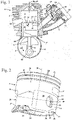
- the two-stroke engine 1 shows schematically an embodiment of a two-stroke engine 1.
- the two-stroke engine 1 is designed as a single-cylinder engine and has a cylinder 2 in which a combustion chamber 3 is formed.
- the combustion chamber 3 is delimited by a piston 5 which is mounted in a cylinder bore 15 of the cylinder 2 so that it moves back and forth. 1 indicates the piston 5 at bottom dead center.
- the piston 5 drives a crankshaft 7 via a connecting rod 6 .
- the crankshaft 7 is mounted in a crankcase interior 16 of a crankcase 4 such that it can rotate about an axis of rotation 8 .
- the two-stroke engine 1 can, for example, be the drive motor in a hand-held tool such as a power saw, a cut-off machine, a blower or the like.
- the crankshaft 7 advantageously serves to drive a tool of the implement.
- the piston 5 advantageously has two piston pockets 14, of which 1 one is shown.
- the piston pockets 14 are symmetrical to the in
- the two-stroke engine 1 has an air duct 9 which is connected to an air filter 22 . Fuel-free or low-fuel scavenging air is sucked in by the air filter 22 via the air duct 9 . In the air duct 9 there is an air flap 21 for controlling the quantity of scavenging template air supplied via the air duct 9 .
- the air duct 9 opens out with an air inlet 11 on the cylinder bore 15.
- a mixture duct 10 is provided for supplying a fuel/air mixture.
- the mixture channel 10 is connected to the air filter 22 via a carburetor 18 .
- a throttle valve 19 and a choke valve 20 are pivotably mounted in the carburetor 18 .
- the throttle flap 19 and the choke flap 20 are used to adjust the quantity of combustion air and fuel supplied via the mixture channel 10.
- the fuel can also be supplied in a different way, for example via an injection valve or a carburetor with an electromagnetic valve.
- the mixture channel 10 opens out with a mixture inlet 12 on the cylinder bore 15.
- the air inlet 11 and the mixture inlet 12 are controlled by the piston 5.
- the two-stroke engine 1 has overflow channels 13 which open into the combustion chamber 3 with overflow windows 17 .
- the overflow windows 17 are also controlled by the piston 5 .
- the in 1 Transfer channels 13, not shown in detail connect the crankcase interior 16 to the combustion chamber 3.
- fuel/air mixture is drawn into the crankcase interior 16 through the mixture inlet 12 .
- the upward stroke of the piston designates the movement of the piston 5 from the in 1 shown position of the piston 5 in the bottom dead center in the direction of the combustion chamber 3, i.e. in 1 in the direction of arrow 70.
- the piston pockets 14 each connect an air inlet 11 with overflow windows 17.
- the mixture already present in the combustion chamber 3 is simultaneously compressed and ignited in the region of the top dead center of the piston 5 by a spark plug (not shown).
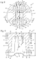
- the piston pockets 14 have an upper control edge 29 which is advantageously arranged in the region of the top dead center of the piston 5 in such a way that the overflow windows 17 are arranged to completely overlap with the piston pocket 14 .
- the upper control edge 29 is the control edge of the piston pocket 14 which is closest to the combustion chamber 3 .
- the piston pocket 14 also has a lower control edge 30 which faces the crankcase 4 .
- the lower control edge 30 is the most distant from the combustion chamber 3 control edge of the piston pocket 14 and delimits the piston pocket 14 in the direction of the crankcase 4.
- the lower control edge 30 is advantageously arranged in such a way that the air inlet 11 completely overlaps the piston pocket 14.
- the piston 5 has an edge 31 on its side facing the crankcase 4.
- the edge 31 is the boundary of the piston 5 facing the crankcase 4.
- a web 32 is formed between the piston pockets 14 and the edge 31, which is formed by a section of a piston 26 is formed.
- the edge 31 forms an underside of the piston 5.
- the piston 5 has a piston head 25 which delimits the combustion chamber 3 and which runs approximately perpendicularly to a longitudinal center axis 50 of the piston 5 in the exemplary embodiment.
- the piston 5 also has a piston skirt 26 which adjoins the piston head and which advantageously follows the course of the cylinder bore 15 .
- the outside of the piston skirt 26 is advantageously approximately cylindrical.
- the outside of the piston skirt 26 can have an exactly cylindrical cross section or one that deviates slightly from the cylindrical shape, for example a slightly oval or elliptical cross section.
- the longitudinal central axis 50 of the piston 5 is the central axis of the piston skirt 26.
- two piston ring grooves 24 are provided adjacent to the piston crown 25 on the piston skirt 26, which are used to accommodate piston rings, not shown.
- a bore 41 is shown in one of the piston ring grooves 24 and serves to receive a locking pin for a piston ring.
- a corresponding bore is also available for the other piston ring groove 24 on the in 2 not shown side of the piston 5 is provided.
- a recess 27 is provided on the piston skirt 26 between each piston pocket 14 and the lower piston ring groove 24 .
- the depression 27 serves to reduce the weight of the piston 5.
- the depression 27 is designed in such a way that during a piston stroke it only overlaps with one or with both overflow windows 17, but not with the air inlet 11. As a result, no connection can be made between the air inlet 11 and the overflow windows 17 via the depression 27 .
- the connecting rod 6 ( 1 ) is connected to the piston 5 via a piston pin, not shown, which is held in piston pin receptacles 53 of the piston 5.
- the piston pin receptacles 53 in the exemplary embodiment lie completely within the piston pockets 14.
- the piston pin receptacles 53 are advantageously located in the space between the control edges 29 and 30 of the piston pockets 14.
- the piston pocket 14 is bounded by a rear wall 58 toward the crankcase interior 16.
- connecting ribs 38 are provided inside the piston skirt 26, which connect the rear wall 58 of the piston pockets 14 to the piston skirt 26.
- the piston 5 On the sides of the piston pockets 14 facing the recess 33 in the circumferential direction, the piston 5 has boundary edges 36 near the inlet on the piston pockets 14.
- the boundary edges 36 near the inlet run approximately parallel to the longitudinal center axis 50.
- the piston pockets 14 also have boundary edges 69 near the outlet.
- the boundary edges 69 near the outlet also run approximately parallel to the longitudinal center axis 50.
- Each piston pocket 14 is delimited in the direction of the longitudinal center axis 50 by the control edges 29 and 30 and in the circumferential direction by the delimiting edges 36 and 69.
- piston skirt 26 On the side facing mixture inlet 12, piston skirt 26 has a recess 33 on the side facing crankcase 4 and remote from combustion chamber 3. At recess 33, the height of piston skirt 26 is reduced.
- the recess 33 is formed as a bulge in the edge 31 in the direction of the piston head 25 .
- the position of the edge 31 on the recess 33 determines the control time at which the mixture inlet 12 ( 1 ) is opened and closed.
- a chamfer 37 is provided on the edge 31 in the area of the recess 33 at the transition of the edge 31 to the outside of the piston skirt 26 .
- the recess 33 has a roof 35 on which the edge 31 is approximately parallel to the piston crown 25 ( 2 ) runs. This is also in 4 shown.
- a transition region 34 in each case borders on the roof 35 of the recess 33 in the circumferential direction on both sides. At the transition area 34, the edge 31 runs inclined to the longitudinal center axis 50 of the piston 5. The inclined course of the transition areas 34 is also shown in FIG 4 shown.
- the transition areas 34 connect the roof 35 with the areas of the edge 31 lying outside the recess 33.
- the piston 5 has a diameter d.
- the diameter d is advantageously the largest diameter of the piston 5 and is measured on an upper side 39 of the piston head 25 in the exemplary embodiment.
- the upper side 39 of the piston crown 25 is the side of the piston crown 25 that delimits the combustion chamber 3 in an engine, for example in the two-stroke engine 1 .
- the top 39 is the piston pin receptacles 53 ( 2 ) facing away from the piston head 25.
- the piston 5 has a height h, which is measured parallel to the longitudinal center axis 50 of the piston 5.
- the height h is the greatest height of the piston 5.
- the diameter d of the piston 5 is advantageously 70% to 140%, in particular 80% to 130%, preferably 90% to 120% of the height h.
- the diameter d is particularly preferably greater than the height h.
- the gudgeon pin mounts 53 ( 2 ) have a central axis which forms a transverse axis 49 of the piston 5.
- the transverse axis 49 is also in 2 shown. in the in 4 In the side view shown, the transverse axis 49 runs perpendicular to the longitudinal center axis 50.
- the piston 5 has a center plane 51 which contains the longitudinal center axis 50 of the piston 5 and which runs perpendicular to the transverse axis 49. in the in 4 shown side view, the longitudinal center axis 50 and the center plane 51 coincide.
- the piston 5 has a sectional plane 52 running perpendicularly to the longitudinal center axis 50.
- a sectional plane 52 that coincides with the transverse axis 49 is shown as an example in the side view shown.
- the cutting plane 52 has a distance m from the top 39 of the piston head 25.
- the upper control edge 29 of the piston pocket 14 has the top 39 a smallest distance e.
- the control edge 29 runs in a plane that runs perpendicular to the longitudinal center axis 50 . runs If the upper control edge 29 is not at a uniform distance from the top 39, then the distance e is measured at the point on the control edge 29 that has the smallest distance from the top 39.
- the distance m of the cutting plane 52 is advantageously greater than the shortest distance e of the control edge 29 to the top 39.
- the cutting plane 52 is therefore in an engine at the crankcase 4 ( 1 ) side facing the upper control edge 29. In the exemplary embodiment, the cutting plane 52 intersects both piston pockets 14.
- the piston 5 has a reduced height i.
- the reduced height i is the distance, measured parallel to the longitudinal center axis 50, of the edge 31 on the roof 35 of the recess 33 from the top 39 of the piston 5.
- the reduced height i on the recess 33 is advantageously 70% to 98%, in particular 80% to 95%.
- the height i is greater than the distance m of the cutting plane 52 to the top 39.
- the distance m is greater than the reduced height i, the cutting plane 52 that is through the Recess 33 runs.
- the height of the piston 5 increases by at least 5%, in particular at least 10%.
- the height h of the piston 5 is therefore at least 105%, in particular at least 110% of the reduced height i at the recess 33.
- the piston 5 has an inlet side 47 on which the recess 33 is arranged. As 1 1, the piston 5 also has an outlet side 48 which controls the outlet 23. The inlet side 47 and the outlet side 48 are of an in 1 drawn-in transverse plane 65 of the piston 5, which separates the longitudinal center axis 50 and the transverse axis 49 ( 2 ) contains. As 1 shows, the crankshaft 8 rotates in a direction of rotation 64 during operation. The crankshaft 7 is connected to the connecting rod 6 at a connecting rod eye 61 .
- the direction of rotation 64 is directed in such a way that the connecting rod eye 61 is located on the outlet side of the transverse plane 65 facing the outlet 23 during the downward stroke of the piston 5 and on the inlet side of the transverse plane 65 facing the mixture inlet 12 and the air inlet 11 during the upward stroke of the piston outlet side
- the transverse plane 65 is the side of the transverse plane 65 on which the outlet side 48 of the piston 5 is located
- the inlet side of the transverse plane 65 is the side of the transverse plane 65 on which the inlet side 47 of the piston 5 is located.
- the connecting rod eye 61 and the recess 33 ( 2 ) on opposite sides of the transverse plane 65.
- the formation of the chamfer 37 on the inlet side 47 of the piston 5 prevents the edge 31 of the piston 5 in the area of the recess 33 from scraping off oil that has accumulated in the cylinder bore 15.
- the web 32 has a height k.
- the height k can be about 1 mm to about 5 mm, in particular about 1 mm to about 3 mm.
- the height of the web 32 does not have to be constant, but can change along the circumference of the piston 5 .
- the web 32 serves to seal between the volume enclosed by the piston pocket 26 and the cylinder bore 15 and the crankcase interior 16.
- the piston pin receptacles 53 are formed on piston pin bosses 28 that protrude into the space enclosed by the piston skirt 26 .
- figure 5 shows a section along the cutting plane 52. How figure 5 shows, the center plane 51 intersects the piston skirt 26 on the inlet side 47 at a point 44.
- the point 44 has the shape of a line aligned radially to the longitudinal center axis 50 of the piston 5, since it represents the intersection of the cutting plane 52 with the center plane 51.
- Position 44 is also in 4 drawn.
- the piston skirt 26 has a wall thickness b.
- a thickened area 40 is arranged on both sides of the point 44 in the circumferential direction between the point 44 and the boundary edge 36 of the piston pockets 14 .
- the piston skirt 26 has a greatest wall thickness a, which is at least 1.1 times the wall thickness b at the point 44.
- Wall thickness a is preferably at least 1.15 times, in particular at least 1.2 times, wall thickness b.
- the wall thickness a in the thickened area 40 is not constant over the entire thickened area 40, but increases from the area arranged adjacent to the point 44, viewed in the circumferential direction, and then decreases again.
- the thickened area 40 extends over a circumferential angle ⁇ around the longitudinal central axis 50, which is advantageously from 5° to 45°, in particular from 10° to 35°, preferably from 15° to 25°.
- the circumferential angle ⁇ is measured between a first reference line 71 and a second reference line 72 .
- the first reference line 71 connects the longitudinal center axis 50 in the section plane 52 to the point on the piston skirt 26 at which the wall thickness of the piston skirt 26 increases compared to the wall thickness b at the point 44 .
- the second reference line 72 connects the longitudinal center axis 50 in the section plane 52 to the boundary edge 36 of the piston pocket 14 near the inlet .
- the wall thickness c at the boundary edge 36 is greater than the wall thickness b at the point 44.
- the wall thickness c at the boundary edge 36 is advantageously 1.05 times, in particular at least 1.1 times, the wall thickness b at the point 44.
- the piston pockets 14 are arranged and formed mirror-symmetrically to one another in relation to the center plane 51 .
- the thickened regions 40 are arranged and formed mirror-symmetrically to one another in relation to the central plane 51 .
- both the piston pockets 14 and the thickened areas 40 are arranged and formed mirror-symmetrically to one another in relation to the center plane 51 .
- the piston skirt 26 has an inner contour 46 that runs straight. However, it can also be provided that the inner contour 46 is curved.
- the thickened area 40 is formed in each case by a thickened area 45 on the inside of the piston skirt 26 .
- the thickened areas 40 advantageously extend over at least 50% of the height h of the piston 5 ( 2 ). As 6 shows, the thickened areas 40 extend in the embodiment to the edge 31, wherein the inner contour of the piston 5 with a chamfer or a rounding in the edge 31 merges. In the exemplary embodiment, the thickened areas 40 connect the piston head 25 to the rim 31 of the piston 5.
- the inner contour 46 of the thickened areas 40 can run parallel to the longitudinal center axis 50 or be slightly inclined to the longitudinal center axis 50, resulting in a slight draft angle. The draft allows the piston 5 to be removed from the mold during production in a casting process.
- the draft angle is advantageously 0.5° to 3°.
- a cutting plane 52 ( 4 ) which includes the transverse axis 49.
- the thickened area 40 is correspondingly in a sectional plane that runs perpendicular to the longitudinal center axis 50 on the control edge 29, and/or in a sectional plane that is on an in 7 shown lower edge 66 of the piston pin receptacles 53 perpendicular to the longitudinal center axis 50, given.
- the lower edge 66 of the piston pin receptacles 53 is that of the upper side 39 ( 4 ) of the piston crown 25 remote edge of the piston pin receptacles 53.
- the thickened region 40 preferably runs at least from a sectional plane containing the control edge 29 and running perpendicularly to the longitudinal center axis 50 to the edge 31 at the recess 33.
- 26 ribs 42 and 43 are provided on the inside of the piston skirt.
- the ribs 42 and 43 connect the piston skirt 26 to the piston head 25.
- a rib 43 is arranged on the inlet side 47 and a rib 43 is arranged on the outlet side 48.
- the ribs 43 run in relation to the transverse plane 65 ( figure 5 ) advantageously mirror-symmetrical to each other.
- the ribs 43 are intersected by the center plane 51 and are mirror-symmetrical to the center plane 51 .
- Ribs 42 are provided on both sides of the ribs 43 on the inlet side 47 and on the outlet side 48 .
- the ribs 42 and 43 are each formed individually and connected to one another exclusively via the piston skirt 26 and the piston head 25, but not directly. As figure 5 shows, the ribs 42 and 43 end above the cutting plane 52 and do not protrude into the cutting plane 52.
- the chamfer 37 on the inlet side 47 extends as 6 shows, over a circumferential angle ⁇ around the longitudinal central axis 50, which is less than 180°, in particular less than 150°, preferably less than 120°, in particular less than 90°. In the exemplary embodiment, an angle ⁇ of less than 60° is provided.
- a chamfer 59 is also arranged on the edge 31 of the piston skirt 26 on the outlet side 48 .
- the chamfer 59 extends, as in 6 is drawn in schematically, over a circumferential angle ⁇ , which is also less than 180°, in particular less than 150°, preferably less than 120°, advantageously less than 100°.
- the circumferential angle ⁇ is advantageously larger than the circumferential angle ⁇ .
- a circumferential angle ⁇ of approximately 80° to 100° is provided.
- the angles ⁇ and ⁇ are advantageously selected in such a way that the chamfers 37 and 59 run predominantly in the area arranged between the piston pockets 14 in the circumferential direction.
- the piston 5 rests against the cylinder bore 15 on the inlet side 47 or on the outlet side 48 due to the forces exerted via the connecting rod 6 .
- the piston 5 tilts slightly about the transverse axis 49.
- the chamfers 37 and 59 advantageously extend in the peripheral regions of the piston 5, which bear against the cylinder bore 15 of the two-stroke engine 1 during operation.
- connecting ribs 38 each run between a piston pin boss 28 and the piston skirt 26.
- the connecting ribs 38 extend approximately parallel to the center plane 51.
- the ribs 42 and 43 each have at least one end face 67 projecting into the interior of the piston 5.
- the end faces 67 advantageously run along the ribs 42 and 43 in a curved manner, namely in a concave manner.
- a stop surface 54 formed on the piston head 26 is also shown. During the manufacture of the piston 5, the stop surface 54 serves as a stop for fixing the piston 5 during the external machining of the piston skirt 26.
- the depressions 27 extend as 8 points, into the piston pin bosses 28, so that in the piston pin bosses 28 between the piston pin receptacle 53 and the piston head 25 ( 7 ) no accumulation of material is formed.
- the recesses 27 serve to reduce the weight of the piston 5.
- the configuration of the ribs 42 and 43 is shown in detail.
- mutually opposite ribs 42 and 43 formed mirror-symmetrically with respect to the transverse plane 65 each have a spacing from one another.
- Opposite ribs 42 have a spacing p from one another. The distance p is advantageously more than 10% of the diameter d of the piston 5 ( 4 ).
- the mutually opposite ribs 43 have a distance r from one another, which is advantageously smaller than the distance p. in the in 8
- the ribs 42 on the piston skirt 26 shown have a thickness n.
- the thickness n is the thickness of the ribs 42.
- the ribs 43 have a thickness o, which is greater than the thickness n.
- the thickness o is the thickness of the ribs 43.
- the thickness o is advantageously 1.1 to 1.8 times the thickness n.
- How 8 also shows the ribs 42 and 43 are at a small distance from one another and at a distance from the gudgeon pin bosses 28.
- the connecting ribs 42 are, as 8 shows, are arranged on the thickened areas 40 and additionally reinforce the piston skirt 26 on the thickened areas 40.
- ribs 42 and 43 located on inlet side 47 are shown.
- the ribs 42 each have a tip 62 which is arranged on the sides of the ribs 42 facing away from the top 39 .
- the tip 62 has a distance f from the top 39.
- the distance f is advantageously 30% to 70% of the height h of the piston 5.
- the rib 43 has a tip 63 which faces away from the top 39 and has a distance g from the top 39.
- the distance g is significantly larger than that Distance f and is advantageously 1.1 times to 1.5 times the distance f.
- the distance g is advantageously 50% to 80% of the height h of the piston 5.
- FIG. 9 12 also shows the connecting rib 38.
- a recess 56 is formed between the connecting rib 38 and the piston skirt 26.
- FIG. The connecting rib 38 runs as an extension of the rear wall 58 on the piston pocket 14.
- the recess 56 is delimited by the connecting rib 38 and the web 32 and the rear wall 58 of the piston pocket 14 and the piston pin boss 28.
- FIG. 10 shows the outlet side 48 of the piston 5.
- ribs 42 and 43 Arranged on the outlet side 48 are ribs 42 and 43 which are mirror-symmetrical with respect to the transverse plane 65 to the ribs 42 and 43 on the inlet side 47.
- the rib 43 has a tip 63 which is at a distance g from the upper side 39 of the piston 5.
- FIG. The ribs 42 arranged on both sides of the rib 43 each have a tip 62 which is arranged at a distance f from the upper side 39 of the piston 5 .
Landscapes
- Engineering & Computer Science (AREA)
- Chemical & Material Sciences (AREA)
- Combustion & Propulsion (AREA)
- Mechanical Engineering (AREA)
- General Engineering & Computer Science (AREA)
- Pistons, Piston Rings, And Cylinders (AREA)
- Compressor (AREA)
Description
- Die Erfindung betrifft einen Kolben für einen mit Spülvorlage arbeitenden Zweitaktmotor der im Oberbegriff des Anspruchs 1 angegebenen Gattung und einen Zweitaktmotor.
- Aus der
DE 10 2010 008 260 A1 ist ein Kolben für einen mit Spülvorlage arbeitenden Zweitaktmotor bekannt, der Kolbentaschen besitzt, die zur Verbindung eines an der Zylinderbohrung mündenden Lufteinlasses mit Überströmfenstern von Überströmkanälen dienen. Über die Kolbentasche wird Luft aus dem Lufteinlass in den Überströmkanälen vorgelagert. In dem zwischen den Kolbentaschen liegenden Umfangsbereich besitzt der Kolben an seinem dem Kolbenboden abgewandten Rand eine Ausnehmung, an der der Kolben eine verringerte Höhe besitzt. - Auch die
JP H03 119553 U JP S60 55753 U - Die
BE 893 995 A - Die
JP H02 119665 A - Der Erfindung liegt die Aufgabe zugrunde, einen Kolben für einen mit Spülvorlage arbeitenden Zweitaktmotor zu schaffen, der eine hohe Lebensdauer besitzt. Eine weitere Aufgabe der Erfindung besteht darin, einen Zweitaktmotor mit einem Kolben anzugeben, der eine hohe Lebensdauer besitzt. Bezüglich des Kolbens wird die Aufgabe durch einen Kolben mit den Merkmalen des Anspruchs 1 gelöst. Bezüglich des Zweitaktmotors wird die Aufgabe durch einen Zweitaktmotor mit den Merkmalen des Anspruchs 5 gelöst.
- Es hat sich gezeigt, dass bei einem Kolben für einen mit Spülvorlage arbeitenden Zweitaktmotor, der einen Kolbenboden und ein Kolbenhemd besitzt, wobei die Mittelachse des Kolbenhemds eine Längsmittelachse des Kolbens bildet, wobei der Kolben zwei Kolbenbolzenaugen besitzt, deren Mittelachse eine Querachse des Kolbens bildet, wobei der Kolben eine Mittelebene besitzt, die die Längsmittelachse des Kolbens enthält und die senkrecht zur Querachse des Kolbens verläuft, wobei der Kolben zwei Kolbentaschen besitzt, die auf gegenüberliegenden Seiten der Mittelebene angeordnet sind, wobei das Kolbenhemd einen dem Kolbenboden abgewandten Rand besitzt und wobei der Rand im Umfangsbereich zwischen den Kolbentaschen eine Ausnehmung besitzt, an der das Kolbenhemd eine verringerte Höhe besitzt, eine höhere Lebensdauer des Kolbens erreicht wird, wenn der Rand an der Ausnehmung an der radial außen liegenden Seite des Kolbens eine Fase besitzt.
- Es hat sich gezeigt, dass es an der Ausnehmung, an der das Kolbenhemd die verringerte Höhe besitzt, zu erhöhtem Verschleiß kommen kann. Es hat sich gezeigt, dass dieser Verschleiß dadurch hervorgerufen werden kann, dass im Bereich der Ausnehmung vom Rand des Kolbens Öl, das sich an der Zylinderbohrung abgesetzt hat, abgeschabt wird. Dadurch wird die Reibung zwischen Kolben und Zylinderbohrung in diesem Bereich erhöht. Um die Lebensdauer des Kolbens und eines mit dem Kolben arbeitenden Zweitaktmotors zu erhöhen, ist nun vorgesehen, dass der Rand an der Ausnehmung an der radial außen liegenden Seite des Kolbens eine Fase besitzt. Die Fase verhindert, dass der Rand an der Ausnehmung mit der Zylinderbohrung in Kontakt kommen kann. Durch die Fase ist der Bereich des Rands des Kolbens von der Zylinderbohrung geringfügig zurückversetzt, so dass der Kolben nicht mit seinem Rand, sondern mit dem angrenzenden Bereich des Kolbenhemds mit der Zylinderbohrung in Kontakt kommt. Die Fase bewirkt, dass der Kolben auf einen an der Zylinderbohrung bestehenden Ölfilm aufschwimmt und den Ölfilm nicht von der Zylinderbohrung abschabt. Die Fase besitzt im Unterschied zu einem abgerundeten, also in einem Radius verlaufenden Rand des Kolbens in jedem Bereich die gleiche Neigung zur Zylinderbohrung. Aufgrund von Fertigungstoleranzen kann die Breite der Fase durch die Außenbearbeitung des Kolbens von einer Sollbreite abweichen. Aufgrund des gleichmäßigen Neigungswinkels der Fase wird der gewünschte Neigungswinkel in diesem Bereich weitgehend unabhängig von Fertigungstoleranzen sichergestellt.
- Bei einem Zweitaktmotor mit einem Kolben ist vorgesehen, dass der Zweitaktmotor einen Zylinder besitzt, in dessen Zylinderbohrung ein Brennraum ausgebildet ist, der von dem Kolben begrenzt ist, wobei der Kolben über ein Pleuel eine in einem Kurbelgehäuse drehbar gelagerte Kurbelwelle antreibt, wobei das Pleuel an einem Pleuelauge an der Kurbelwelle gelagert ist, wobei der Kolben eine Querebene besitzt, die die Längsmittelachse und die Querachse des Kolbens enthält. Es ist vorteilhaft vorgesehen, dass die Fase an der Seite des Kolbens angeordnet ist, die beim Abwärtshub des Kolbens auf der dem Pleuelauge gegenüberliegenden Seite der Querebene des Kolbens angeordnet ist. Die Fase ist dadurch in dem Bereich des Rands des Kolbens angeordnet, der aufgrund der Schrägstellung des Pleuels beim Abwärtshub des Kolbens mit der Zylinderbohrung in Kontakt ist.
- Vorteilhaft besitzt der Zweitaktmotor einen vom Kolben gesteuerten Gemischeinlass ins Kurbelgehäuse. Die Fase ist vorteilhaft an dem den Gemischeinlass steuernden Bereich des Rands angeordnet. Über die Lage des Rands an der Ausnehmung des Kolbens lässt sich die Steuerzeit des Gemischeinlasses, also der Zeitpunkt, bei dem der Gemischeinlass beim Aufwärtshub des Kolbens in den Kurbelgehäuseinnenraum öffnet, einstellen. Dadurch kann es gegenüber einer für die Führung des Kolbens optimalen Länge des Kolbenhemds zu einer in diesem Bereich verkürzten Länge des Kolbenhemds kommen. Über die Fase kann dennoch auf einfache Weise ein Abschaben von Öl durch den Rand des Kolbens von der Zylinderbohrung vermieden werden. Dadurch kann ein Zweitaktmotor mit ausreichender Füllung des Kurbelgehäuses mit Kraftstoff/LuftGemisch und gleichzeitig mit hoher Lebensdauer erzielt werden.
- Die Ausnehmung ist an einer Einlassseite des Kolbens angeordnet, und der Kolben besitzt eine gegenüberliegende Auslassseite. Die Einlassseite und die Auslassseite sind vorteilhaft durch die Querebene des Kolbens voneinander getrennt. Der Rand des Kolbens besitzt auch an der Auslassseite eine Fase. Die Fase an der Einlassseite erstreckt sich vorteilhaft über einen Umfangswinkel um die Längsmittelachse des Kolbens von weniger als 180°, insbesondere von weniger als 150°. Bevorzugt ist ein Winkel von weniger als 120°, insbesondere von weniger als 90° vorgesehen. Vorteilhaft erstreckt sich die Fase an der Auslassseite ebenfalls über einen Umfangswinkel von weniger als 180°, insbesondere weniger als 150°, bevorzugt weniger als 120°. In besonders bevorzugter Gestaltung erstreckt sich die Fase an der Auslassseite über einen Umfangswinkel von weniger als 100°. Der Umfangswinkel, über den sich die Fase an der Auslassseite erstreckt, ist größer als der Umfangswinkel, über den sich die Fase an der Einlassseite erstreckt.
- Für einen Kolben kann vorgesehen sein, dass der Kolben mindestens eine Schnittebene senkrecht zur Längsmittelachse des Kolbens besitzt, deren Abstand zur Oberseite des Kolbenbodens größer als der geringste Abstand der Kolbentasche zum Kolbenboden ist. Das Kolbenhemd besitzt eine Stelle, an der eine Mittelebene des Kolbens das Kolbenhemd in dieser Schnittebene schneidet. In Umfangsrichtung zwischen der Kolbentasche und dieser Stelle ist in dieser Schnittebene ein verdickter Bereich angeordnet, dessen größte Wandstärke mindestens das 1,1fache der Wandstärke an der Stelle beträgt. Der verdickte Bereich ist damit in Umfangsrichtung zwischen der Kolbentasche und der Schnittebene des Kolbenhemds mit der Mittelebene angeordnet. In Richtung der Längsmittelachse des Kolbens liegt der verdickte Bereich in einer Schnittebene, die zur Oberseite des Kolbenbodens einen größeren Abstand als der geringste Abstand der Kolbentasche zum Kolbenboden hat. Die Schnittebene, in der der verdickte Bereich angeordnet ist, liegt demnach zwischen einer Oberkante der Kolbentasche und der Unterseite des Kolbens. Der verdickte Bereich kann sich dabei auch zwischen der Kolbentasche und der Oberseite des Kolbenbodens erstrecken.
- Es hat sich gezeigt, dass in Umfangsrichtung zwischen der Kolbentasche und der Stelle, an der die Mittelebene das Kolbenhemd schneidet, erhöhte Belastungen auftreten. Durch den verdickten Bereich können diese Belastungen besser aufgenommen und in die angrenzenden Bereiche des Kolbenhemds abgeleitet werden, so dass sich eine höhere Stabilität und dadurch eine erhöhte Lebensdauer des Kolbens ergibt. Dadurch, dass der verdickte Bereich zwischen der Stelle und der Kolbentasche angeordnet ist, und sich nicht über den gesamten Umfangsbereich zwischen den Kolbentaschen erstreckt, kann insgesamt ein verringertes Gewicht des Kolbens erreicht werden.
- Vorteilhaft enthält eine Schnittebene, in der der verdickte Bereich angeordnet ist, die Querachse des Kolbens. Insbesondere verläuft eine Schnittebene, in der der verdickte Bereich angeordnet ist, an einer entfernt vom Kolbenboden liegenden Unterseite einer Kolbenbolzenaufnahme. Besonders vorteilhaft verläuft eine Schnittebene, in der der verdickte Bereich angeordnet ist, an einem dem Kolbenboden abgewandten Rand des Kolbens. Insbesondere verläuft eine Schnittebene, in der der verdickte Bereich angeordnet ist, an einer dem Kolbenboden abgewandten Unterseite des Kolbens. Der verdickte Bereich erstreckt sich vorteilhaft über mindestens 50% der parallel zur Längsmittelachse gemessenen Höhe des Kolbens. Bevorzugt erstreckt sich der verdickte Bereich vom Kolbenboden bis zum Rand des Kolbens.
- Vorteilhaft besitzt der Kolben zwei verdickte Bereiche. Bevorzugt besitzt der Kolben zwei Kolbentaschen auf gegenüberliegenden Seiten der Mittelebene, wobei sich zwischen jeder Kolbentasche und dieser Stelle ein verdickter Bereich erstreckt. Die verdickten Bereiche sind insbesondere spiegelsymmetrisch zur Mittelebene angeordnet. Das Kolbenhemd besitzt vorteilhaft einen dem Kolbenboden abgewandten Rand. Der dem Kolbenboden abgewandte Rand ist an der Unterseite des Kolbens angeordnet. Bevorzugt ist im Umfangsbereich zwischen den Kolbentaschen eine Ausnehmung vorgesehen, an der das Kolbenhemd eine verringerte Höhe besitzt. Der verdickte Bereich überlappt die Ausnehmung vorteilhaft mindestens teilweise in Umfangsrichtung. Es hat sich gezeigt, dass insbesondere in dem Bereich, in dem sich die Höhe des Kolbens von der im Bereich der Kolbentasche vorgesehenen Höhe zu der verringerten Höhe an der Ausnehmung verringert, Spannungen auftreten können, die zu Rissen in diesem Bereich führen. Diese Rissbildung wird durch den verdickten Bereich verhindert, so dass sich bereits durch vergleichsweise geringe Aufdickung des Kolbenhemds in dem verdickten Bereich eine erhöhte Lebensdauer des Kolbens ergibt.
- In besonders vorteilhafter Gestaltung besitzt der Rand an der Ausnehmung der radial außen liegenden Seite des Kolbens eine Fase. Die Fase verhindert beim Aufwärtshub des Kolbens, dass an der Zylinderbohrung angelagertes Öl durch den Kolben abgeschabt wird, so dass sich eine verbesserte Schmierung des Kolbens in der Zylinderbohrung ergibt, wodurch die Reibung verringert und dadurch die Lebensdauer des Kolbens und des Zweitaktmotors erhöht wird.
- Die Ausnehmung, an der das Kolbenhemd eine verringerte Höhe besitzt, geht vorteilhaft mit einem Übergangsbereich in den in Umfangsrichtung angrenzenden Bereich des Kolbenhemds über. In dem Übergangsbereich vergrößert sich die Höhe des Kolbens vorteilhaft um mindestens 5%, insbesondere um mindestens 10%. In besonders vorteilhafter Gestaltung erstreckt sich der verdickte Bereich bis an den Rand des Kolbens. Dadurch kann unmittelbar an dem Übergangsbereich die Entstehung von erhöhten Spannungen und dadurch die Entstehung von Rissen im Kolbenhemd verhindert werden. Der verdickte Bereich überdeckt in Umfangsrichtung vorteilhaft den gesamten Übergangsbereich. In besonders vorteilhafter Gestaltung erstreckt sich der verdickte Bereich bis an den Rand des Kolbens.
- Eine einfache Gestaltung ergibt sich, wenn die Innenkontur des Kolbenhemds in dem verdickten Bereich in dieser Schnittebene gerade verläuft. Durch den geraden Verlauf des verdickten Bereichs an der Innenkontur des Kolbenhemds wird eine besonders einfache Gestalt und gleichzeitig eine ausreichend große Verdickung in der Mitte des verdickten Bereichs erreicht. Das Kolbenhemd verläuft vorteilhaft näherungsweise zylindrisch, und die Innenkontur des Kolbenhemds in dem verdickten Bereich bildet eine Sekante an den näherungsweise kreisbogenförmigen Verlauf der Kontur des Kolbenhemds. An der Außenseite des verdickten Bereichs verläuft das Kolbenhemd vorteilhaft bogenförmig, insbesondere näherungsweise kreisbogenförmig um die Längsmittelachse des Kolbens. Es kann vorgesehen sein, dass das Kolbenhemd einen von der Kreisform abweichenden Querschnitt besitzt. Das Kolbenhemd kann insbesondere eine elliptische, ovale oder kleeblattförmige Gestalt aufweisen. Ein kleeblattförmiger Querschnitt ist dabei ein Querschnitt, bei dem der Durchmesser in zwei schräg zueinander stehenden Richtungen verringert ist. Die Abweichung des Querschnitts von der Kreisform ist dabei vorteilhaft sehr gering.
- Die Kolbentasche besitzt vorteilhaft eine dem verdickten Bereich in Umfangsrichtung zugewandte Begrenzungskante. Die Wandstärke des Kolbenhemds an der Begrenzungskante ist dabei bevorzugt geringer als die größte Wandstärke des verdickten Bereichs. Die Wandstärke des Kolbenhemds nimmt demnach zwischen dem verdickten Bereich und der Kolbentasche in Umfangsrichtung ab. Die Wandstärke an der Begrenzungskante ist dabei vorteilhaft größer als die Wandstärke an der Stelle, an der die Mittelebene das Kolbenhemd schneidet. Die Wandstärke an der Begrenzungskante beträgt bevorzugt mindestens das 1,1fache der Wandstärke an der Stelle, an der die Mittelebene das Kolbenhemd schneidet.
- Um eine erhöhte Steifigkeit des Kolbens und gleichzeitig eine gute Wärmeabfuhr vom Kolbenboden zu erreichen, ist vorgesehen, dass der Kolben vorteilhaft mindestens eine Rippe besitzt, die den Kolbenboden mit dem Kolbenhemd verbindet. Bevorzugt schließt mindestens eine Rippe radial innerhalb des verdickten Bereichs an den verdickten Bereich an. Über die Rippe wird eine zusätzliche Stabilisierung des Kolbenhemds in dem verdickten Bereich erreicht. Bevorzugt erstreckt sich die Rippe, die radial innerhalb des verdickten Bereichs an den verdickten Bereich anschließt, nicht über die gesamte Höhe des Kolbens, sondern besitzt zum Rand des Kolbens einen Abstand. Die Rippe erstreckt sich vorteilhaft über mindestens 25% der Höhe des Kolbens. Bevorzugt erstreckt sich die Rippe über höchstens 80% der Höhe des Kolbens. Vorteilhaft ist mindestens eine Rippe vorgesehen, die radial innerhalb der Stelle, an der die Mittelebene des Kolbens das Kolbenhemd schneidet, an das Kolbenhemd anschließt.
- Der Kolben besitzt vorteilhaft mindestens zwei Rippen, die unterschiedliche Höhen aufweisen. In besonders vorteilhafter Gestaltung ist eine Rippe, die an die Stelle, an der die Mittelebene das Kolbenhemd schneidet, anschließt, höher als die Rippe, die an den verdickten Bereich anschließt. Bevorzugt ist für alle Rippen des Kolbens eine Höhe von mindestens 25% der Höhe des Kolbens und höchstens 80% der Höhe des Kolbens vorgesehen. Der Kolben besitzt vorteilhaft eine Querebene, die eine Längsmittelachse von Kolbenbolzenaufnahmen des Kolbens sowie die Längsmittelachse des Kolbens enthält. Vorteilhaft ist mindestens eine Rippe auf der dem verdickten Bereich gegenüberliegenden Seite der Querebene angeordnet. In besonders vorteilhafter Gestaltung sind auf beiden Seiten der Querebene spiegelsymmetrisch zur Querebene angeordnete Rippen vorgesehen.
- Vorteilhaft besteht der Kolben aus Leichtmetall, insbesondere aus Magnesium.
- Für einen Zweitaktmotor mit einem Kolben ist vorteilhaft vorgesehen, dass der Zweitaktmotor einen Zylinder besitzt, in dessen Zylinderbohrung ein Brennraum ausgebildet ist, der von dem Kolben begrenzt ist. Der Kolben treibt eine in einem Kurbelgehäuse drehbar gelagerte Kurbelwelle an. Der Zweitaktmotor besitzt mindestens einen Überströmkanal, der in mindestens einer Stellung des Kolbens einen Kurbelgehäuseinnenraum des Kurbelgehäuses mit dem Brennraum verbindet. Der Zweitaktmotor besitzt einen Luftkanal zur Zufuhr von Spülvorlagenluft, der mit einem Lufteinlass an der Zylinderbohrung mündet. Die Kolbentasche liegt in mindestens einer Stellung des Kolbens mindestens teilweise in Überdeckung mit dem Lufteinlass und mit einem Überströmfenster des Überströmkanals. Über die Kolbentasche kann dadurch Spülvorlagenluft aus dem Lufteinlass in dem mindestens einen Überströmkanal vorgelagert werden. Die Spülvorlagenluft ist dabei kraftstoffarme oder kraftstofffreie Verbrennungsluft.
- Ein Ausführungsbeispiel der Erfindung wird im Folgenden anhand der Zeichnung erläutert. Es zeigen:
- Fig. 1
- eine schematische Schnittdarstellung eines Zweitaktmotors,
- Fig. 2
- eine perspektivische Darstellung des Kolbens des Zweitaktmotors aus
Fig. 1 , - Fig. 3
- einen vergrößerten Ausschnitt eines Bereichs des Rands des Kolbens aus
Fig. 2 , - Fig. 4
- eine Seitenansicht des Kolbens aus
Fig. 2 , - Fig. 5
- einen Schnitt entlang der Linie V-V aus
Fig. 4 , - Fig. 6
- eine perspektivische Ansicht des Kolbens von der dem Kurbelgehäuse zugewandten Seite,
- Fig. 7
- eine perspektivische Schnittdarstellung des Kolbens durch die Mittelebene,
- Fig. 8
- einen Schnitt entlang der Linie VIII-VIII in
Fig. 4 , - Fig. 9
- einen Schnitt entlang der Linie IX-IX in
Fig. 8 , - Fig. 10
- einen Schnitt entlang der Linie X-X in
Fig. 8 . -
Fig. 1 zeigt schematisch ein Ausführungsbeispiel für einen Zweitaktmotor 1. Der Zweitaktmotor 1 ist als Einzylindermotor ausgebildet und besitzt einen Zylinder 2, in dem ein Brennraum 3 ausgebildet ist. Der Brennraum 3 ist von einem Kolben 5 begrenzt, der in einer Zylinderbohrung 15 des Zylinders 2 hin und her gehend gelagert ist.Fig. 1 zeigt den Kolben 5 im unteren Totpunkt. Der Kolben 5 treibt über ein Pleuel 6 eine Kurbelwelle 7 an. Die Kurbelwelle 7 ist in einem Kurbelgehäuseinnenraum 16 eines Kurbelgehäuses 4 um eine Drehachse 8 drehbar gelagert. Der Zweitaktmotor 1 kann beispielsweise der Antriebsmotor in einem handgeführten Arbeitsgerät wie einer Motorsäge, einem Trennschleifer, einem Blasgerät oder dergleichen sein. Die Kurbelwelle 7 dient vorteilhaft zum Antrieb eines Werkzeugs des Arbeitsgeräts. Der Kolben 5 besitzt vorteilhaft zwei Kolbentaschen 14, von denen inFig. 1 eine gezeigt ist. Die Kolbentaschen 14 sind symmetrisch zu der inFig. 1 gezeigten Schnittebene am Kolben 5 angeordnet. - Der Zweitaktmotor 1 besitzt einen Luftkanal 9, der mit einem Luftfilter 22 verbunden ist. Über den Luftkanal 9 wird kraftstofffreie oder kraftstoffarme Spülvorlagenluft vom Luftfilter 22 angesaugt. Im Luftkanal 9 ist eine Luftklappe 21 zur Steuerung der über den Luftkanal 9 zugeführten Menge an Spülvorlagenluft angeordnet. Der Luftkanal 9 mündet mit einem Lufteinlass 11 an der Zylinderbohrung 15. Zur Zufuhr von Kraftstoff/Luft-Gemisch ist ein Gemischkanal 10 vorgesehen. Der Gemischkanal 10 ist über einen Vergaser 18 mit dem Luftfilter 22 verbunden. Im Vergaser 18 sind im Ausführungsbeispiel eine Drosselklappe 19 sowie eine Chokeklappe 20 schwenkbar gelagert. Die Drosselklappe 19 und die Chokeklappe 20 dienen zur Einstellung der über den Gemischkanal 10 zugeführten Menge an Verbrennungsluft und Kraftstoff Anstatt mittels eines konventionellen Vergasers 18 kann die Kraftstoffzufuhr auch auf andere Weise, beispielsweise über ein Einspritzventil oder einen Vergaser mit einem elektromagnetischen Ventil, erfolgen. Der Gemischkanal 10 mündet mit einem Gemischeinlass 12 an der Zylinderbohrung 15. Der Lufteinlass 11 und der Gemischeinlass 12 sind vom Kolben 5 gesteuert.
- Der Zweitaktmotor 1 besitzt Überströmkanäle 13, die mit Überströmfenstern 17 in den Brennraum 3 münden. Auch die Überströmfenster 17 sind vom Kolben 5 gesteuert. Im Bereich des unteren Totpunkts des Kolbens 5 verbinden die in
Fig. 1 nicht näher dargestellten Überströmkanäle 13 den Kurbelgehäuseinnenraum 16 mit dem Brennraum 3. Im Betrieb wird beim Aufwärtshub des Kolbens 5 durch den Gemischeinlass 12 Kraftstoff/Luft-Gemisch in den Kurbelgehäuseinnenraum 16 angesaugt. Der Aufwärtshub des Kolbens bezeichnet dabei die Bewegung des Kolbens 5 aus der inFig. 1 gezeigten Stellung des Kolbens 5 im unteren Totpunkt in Richtung auf den Brennraum 3, also inFig. 1 in Richtung des Pfeils 70. Im Bereich des oberen Totpunkts des Kolbens 5 verbinden die Kolbentaschen 14 jeweils einen Lufteinlass 11 mit Überströmfenstern 17. Dadurch wird Spülvorlagenluft aus dem Luftkanal 9 in die Überströmkanäle 13 angesaugt. Beim Aufwärtshub des Kolbens 5 wird gleichzeitig bereits im Brennraum 3 vorhandenes Gemisch komprimiert und im Bereich des oberen Totpunkts des Kolbens 5 von einer nicht dargestellten Zündkerze gezündet. - Der Verbrennungsdruck beschleunigt den Kolben 5 zurück in Richtung auf das Kurbelgehäuse 4. Aus dem Brennraum 3 führt ein vom Kolben 5 gesteuerter Auslass 23. Sobald der Auslass 23 vom Kolben 5 geöffnet wird, strömen die Abgase aus dem Brennraum 3 durch den Auslass 23 aus. Nach weiterem Abwärtshub öffnet der Kolben 5 die Überströmfenster 17 zum Brennraum 3. Die in den Überströmkanälen 13 vorgelagerte Spülvorlagenluft strömt in den Brennraum 3 ein und spült Abgase aus dem Brennraum 3 durch den Auslass 23 aus. Aus dem Kurbelgehäuseinnenraum 16 strömt frisches Kraftstoff/Luft-Gemisch, das im Kurbelgehäuseinnenraum 16 vorkomprimiert wurde, nach. Beim folgenden Motorzyklus wird das Gemisch im Brennraum 3 beim Aufwärtshub des Kolbens 5 komprimiert, während gleichzeitig frisches Gemisch in den Kurbelgehäuseinnenraum 16 und Spülvorlagenluft in die Überströmkanäle 13 angesaugt wird.
- Wie
Fig. 2 zeigt, besitzen die Kolbentaschen 14 eine obere Steuerkante 29, die im Bereich des oberen Totpunkts des Kolbens 5 vorteilhaft so angeordnet ist, dass die Überströmfenster 17 vollständig in Überdeckung mit der Kolbentasche 14 angeordnet sind. Die obere Steuerkante 29 ist die dem Brennraum 3 am nächsten liegende Steuerkante der Kolbentasche 14. Die Kolbentasche 14 besitzt außerdem eine untere Steuerkante 30, die dem Kurbelgehäuse 4 zugewandt liegt. Die untere Steuerkante 30 ist die am weitesten vom Brennraum 3 entfernt liegende Steuerkante der Kolbentasche 14 und begrenzt die Kolbentasche 14 in Richtung auf das Kurbelgehäuse 4. Im oberen Totpunkt des Kolbens 5 ist die untere Steuerkante 30 vorteilhaft so angeordnet, dass der Lufteinlass 11 vollständig in Überdeckung mit der Kolbentasche 14 liegt. Der Kolben 5 besitzt an seiner dem Kurbelgehäuse 4 zugewandten Seite einen Rand 31. Der Rand 31 ist die dem Kurbelgehäuse 4 zugewandte Begrenzung des Kolbens 5. Zwischen den Kolbentaschen 14 und dem Rand 31 ist jeweils ein Steg 32 ausgebildet, der durch einen Abschnitt eines Kolbens 26 gebildet ist. Der Rand 31 bildet eine Unterseite des Kolbens 5. - Der Kolben 5 besitzt einen Kolbenboden 25, der den Brennraum 3 begrenzt und der im Ausführungsbeispiel etwa senkrecht zu einer Längsmittelachse 50 des Kolbens 5 verläuft. Der Kolben 5 besitzt außerdem ein Kolbenhemd 26, das an den Kolbenboden anschließt und das vorteilhaft dem Verlauf der Zylinderbohrung 15 folgt. Die Außenseite des Kolbenhemds 26 verläuft vorteilhaft etwa zylindrisch. Die Außenseite des Kolbenhemds 26 kann dabei einen exakt zylindrischen oder einen geringfügig von der zylindrischen Form abweichenden, beispielsweise leicht ovalen oder elliptischen Querschnitt besitzen. Die Längsmittelachse 50 des Kolbens 5 ist die Mittelachse des Kolbenhemds 26.
- Wie
Fig. 2 zeigt, sind benachbart zum Kolbenboden 25 am Kolbenhemd 26 zwei Kolbenringnuten 24 vorgesehen, die zur Aufnahme von nicht gezeigten Kolbenringen dienen. In einer der Kolbenringnuten 24 ist eine Bohrung 41 gezeigt, die zur Aufnahme eines Sicherungsstifts für einen Kolbenring dient. Eine entsprechende Bohrung ist auch für die weitere Kolbenringnut 24 an der inFig. 2 nicht gezeigten Seite des Kolbens 5 vorgesehen. WieFig. 2 auch zeigt, ist zwischen jeder Kolbentasche 14 und der unteren Kolbenringnut 24 eine Vertiefung 27 am Kolbenhemd 26 vorgesehen. Die Vertiefung 27 dient zur Gewichtsreduzierung des Kolbens 5. Die Vertiefung 27 ist dabei so ausgebildet, dass sie während eines Kolbenhubs nur mit einem oder mit beiden Überströmfenstern 17, jedoch nicht mit dem Lufteinlass 11 in Überdeckung liegt. Dadurch kann über die Vertiefung 27 keine Verbindung zwischen dem Lufteinlass 11 und den Überströmfenstern 17 hergestellt werden. - Das Pleuel 6 (
Fig. 1 ) ist mit dem Kolben 5 über einen nicht gezeigten Kolbenbolzen verbunden, der in Kolbenbolzenaufnahmen 53 des Kolbens 5 gehalten ist. WieFig. 2 zeigt, liegen die Kolbenbolzenaufnahmen 53 im Ausführungsbeispiel vollständig innerhalb der Kolbentaschen 14. Die Kolbenbolzenaufnahmen 53 befinden sich vorteilhaft im Raum zwischen den Steuerkanten 29 und 30 der Kolbentaschen 14. Zum Kurbelgehäuseinnenraum 16 hin wird die Kolbentasche 14 jeweils von einer Rückwand 58 begrenzt. WieFig. 2 auch zeigt, sind im Inneren des Kolbenhemds 26 Verbindungsrippen 38 vorgesehen, die die Rückwand 58 der Kolbentaschen 14 mit dem Kolbenhemd 26 verbinden. Der Kolben 5 besitzt an den in Umfangsrichtung der Ausnehmung 33 zugewandten Seiten der Kolbentaschen 14 einlassnahe Begrenzungskanten 36 an den Kolbentaschen 14. Die einlassnahen Begrenzungskanten 36 verlaufen etwa parallel zur Längsmittelachse 50. Die Kolbentaschen 14 besitzen außerdem auslassnahe Begrenzungskanten 69. Auch die auslassnahen Begrenzungskanten 69 verlaufen etwa parallel zur Längsmittelachse 50. Jede Kolbentasche 14 ist in Richtung der Längsmittelachse 50 von den Steuerkanten 29 und 30 und in Umfangsrichtung von den Begrenzungskanten 36 und 69 begrenzt. - An der dem Gemischeinlass 12 zugewandten Seite besitzt das Kolbenhemd 26 an der dem Kurbelgehäuse 4 zugewandten, dem Brennraum 3 entfernt liegenden Seite eine Ausnehmung 33. An der Ausnehmung 33 ist die Höhe des Kolbenhemds 26 verringert. Die Ausnehmung 33 ist als Ausbuchtung des Rands 31 in Richtung auf den Kolbenboden 25 gebildet. Die Lage des Rands 31 an der Ausnehmung 33 legt die Steuerzeit, bei der der Gemischeinlass 12 (
Fig. 1 ) geöffnet und geschlossen wird, fest. Am Rand 31 ist im Bereich der Ausnehmung 33 eine Fase 37 am Übergang des Rands 31 zur Außenseite des Kolbenhemds 26 vorgesehen. -
Fig. 3 zeigt die Gestaltung der Fase 37 im Einzelnen. Die Ausnehmung 33 besitzt ein Dach 35, an dem der Rand 31 etwa parallel zum Kolbenboden 25 (Fig. 2 ) verläuft. Dies ist auch inFig. 4 gezeigt. An das Dach 35 der Ausnehmung 33 grenzt in Umfangsrichtung beidseitig jeweils ein Übergangsbereich 34 an. An dem Übergangsbereich 34 verläuft der Rand 31 geneigt zur Längsmittelachse 50 des Kolbens 5. Der geneigte Verlauf der Übergangsbereiche 34 ist auch inFig. 4 gezeigt. Die Übergangsbereiche 34 verbinden das Dach 35 mit den außerhalb der Ausnehmung 33 liegenden Bereichen des Rands 31. - Wie
Fig. 4 zeigt, besitzt der Kolben 5 einen Durchmesser d. Der Durchmesser d ist vorteilhaft der größte Durchmesser des Kolbens 5 und im Ausführungsbeispiel an einer Oberseite 39 des Kolbenbodens 25 gemessen. Die Oberseite 39 des Kolbenbodens 25 ist dabei die Seite des Kolbenbodens 25, die den Brennraum 3 in einem Motor, beispielsweise in dem Zweitaktmotor 1, begrenzt. Die Oberseite 39 ist die den Kolbenbolzenaufnahmen 53 (Fig. 2 ) abgewandte Seite des Kolbenbodens 25. Der Kolben 5 besitzt eine Höhe h, die parallel zur Längsmittelachse 50 des Kolbens 5 gemessen ist. Die Höhe h ist die größte Höhe des Kolbens 5. Der Durchmesser d des Kolbens 5 beträgt vorteilhaft 70% bis 140%, insbesondere 80% bis 130%, bevorzugt 90% bis 120% der Höhe h. Besonders bevorzugt ist der Durchmesser d größer als die Höhe h. - Die Kolbenbolzenaufnahmen 53 (
Fig. 2 ) besitzen eine Mittelachse, die eine Querachse 49 des Kolbens 5 bildet. Die Querachse 49 ist auch inFig. 2 gezeigt. In der inFig. 4 gezeigten Seitenansicht verläuft die Querachse 49 senkrecht zur Längsmittelachse 50. Der Kolben 5 besitzt eine Mittelebene 51, die die Längsmittelachse 50 des Kolbens 5 enthält und die senkrecht zur Querachse 49 verläuft. In der inFig. 4 gezeigten Seitenansicht fallen die Längsmittelachse 50 und die Mittelebene 51 zusammen. Der Kolben 5 besitzt eine senkrecht zur Längsmittelachse 50 verlaufende Schnittebene 52. In der inFig. 4 gezeigten Seitenansicht ist eine Schnittebene 52 exemplarisch eingezeichnet, die mit der Querachse 49 zusammenfällt. Die Schnittebene 52 besitzt einen Abstand m zur Oberseite 39 des Kolbenbodens 25. Die obere Steuerkante 29 der Kolbentasche 14 besitzt zur Oberseite 39 einen geringsten Abstand e. Im Ausführungsbeispiel verläuft die Steuerkante 29 in einer Ebene, die senkrecht zur Längsmittelachse 50 verläuft. Verläuft die obere Steuerkante 29 nicht in gleichmäßigem Abstand zur Oberseite 39, so ist der Abstand e an der Stelle der Steuerkante 29 gemessen, die den geringsten Abstand zur Oberseite 39 besitzt. Der Abstand m der Schnittebene 52 ist vorteilhaft größer als der geringste Abstand e der Steuerkante 29 zur Oberseite 39. Die Schnittebene 52 liegt in einem Motor demnach an der dem Kurbelgehäuse 4 (Fig. 1 ) zugewandten Seite der oberen Steuerkante 29. Im Ausführungsbeispiel schneidet die Schnittebene 52 beide Kolbentaschen 14. - An der Ausnehmung 33 besitzt der Kolben 5 eine verringerte Höhe i. Die verringerte Höhe i ist der parallel zur Längsmittelachse 50 gemessene Abstand des Rands 31 am Dach 35 der Ausnehmung 33 zur Oberseite 39 des Kolbens 5. Die verringerte Höhe i an der Ausnehmung 33 beträgt vorteilhaft 70% bis 98%, insbesondere 80% bis 95% der Höhe h des Kolbens 5. Im Ausführungsbeispiel ist die Höhe i größer als der Abstand m der Schnittebene 52 zur Oberseite 39. Es kann jedoch auch vorgesehen sein, dass der Abstand m größer als die verringerte Höhe i ist, die Schnittebene 52 also durch die Ausnehmung 33 verläuft. In dem Übergangsbereich 34 vergrößert sich die Höhe des Kolbens 5 um mindestens 5%, insbesondere mindestens 10%. Die Höhe h des Kolbens 5 beträgt demnach mindestens 105%, insbesondere mindestens 110% der verringerten Höhe i an der Ausnehmung 33.
- Der Kolben 5 besitzt eine Einlassseite 47, an der die Ausnehmung 33 angeordnet ist. Wie
Fig. 1 zeigt, besitzt der Kolben 5 auch eine Auslassseite 48, die den Auslass 23 steuert. Die Einlassseite 47 und die Auslassseite 48 sind von einer inFig. 1 eingezeichneten Querebene 65 des Kolbens 5 getrennt, die die Längsmittelachse 50 und die Querachse 49 (Fig. 2 ) enthält. WieFig. 1 zeigt, dreht die Kurbelwelle 8 im Betrieb in einer Drehrichtung 64. Die Kurbelwelle 7 ist an einem Pleuelauge 61 mit dem Pleuel 6 verbunden. Die Drehrichtung 64 ist so gerichtet, dass sich das Pleuelauge 61 beim Abwärtshub des Kolbens 5 auf der dem Auslass 23 zugewandten Auslassseite der Querebene 65 befindet und beim Aufwärtshub des Kolbens 5 an der dem Gemischeinlass 12 und dem Lufteinlass 11 zugewandten Einlassseite der Querebene 65. Die Auslassseite der Querebene 65 ist dabei die Seite der Querebene 65, auf der sich die Auslassseite 48 des Kolbens 5 befindet, und die Einlassseite der Querebene 65 ist die Seite der Querebene 65, auf der sich die Einlassseite 47 des Kolbens 5 befindet. Beim Abwärtshub des Kolbens 5 befinden sich das Pleuelauge 61 und die Ausnehmung 33 (Fig. 2 ) auf gegenüberliegenden Seiten der Querebene 65. Durch die Ausbildung der Fase 37 an der Einlassseite 47 des Kolbens 5 wird verhindert, dass der Rand 31 des Kolbens 5 im Bereich der Ausnehmung 33 Öl, das sich in der Zylinderbohrung 15 angelagert hat, abschabt. - Wie
Fig. 4 zeigt, besitzt der Steg 32 eine Höhe k. Die Höhe k kann etwa 1 mm bis etwa 5 mm, insbesondere etwa 1 mm bis etwa 3 mm betragen. Die Höhe des Stegs 32 muss dabei nicht konstant sein, sondern kann sich entlang des Umfangs des Kolbens 5 ändern. Der Steg 32 dient zur Abdichtung zwischen dem von Kolbentasche 26 und Zylinderbohrung 15 eingeschlossenen Volumen und dem Kurbelgehäuseinnenraum 16. - Wie
Fig. 5 zeigt, sind die Kolbenbolzenaufnahmen 53 an Kolbenbolzenaugen 28 ausgebildet, die in den vom Kolbenhemd 26 umschlossenen Raum ragen.Fig. 5 zeigt einen Schnitt entlang der Schnittebene 52. WieFig. 5 zeigt, schneidet die Mittelebene 51 das Kolbenhemd 26 an der Einlassseite 47 an einer Stelle 44. Die Stelle 44 besitzt die Form einer radial zur Längsmittelachse 50 des Kolbens 5 ausgerichteten Linie, da sie den Schnitt der Schnittebene 52 mit der Mittelebene 51 darstellt. Die Stelle 44 ist auch inFig. 4 eingezeichnet. An der Stelle 44 besitzt das Kolbenhemd 26 eine Wandstärke b. WieFig. 5 auch zeigt, ist beidseitig der Stelle 44 in Umfangsrichtung zwischen der Stelle 44 und der Begrenzungskante 36 der Kolbentaschen 14 jeweils ein verdickter Bereich 40 angeordnet. In dem verdickten Bereich 40 besitzt das Kolbenhemd 26 eine größte Wandstarke a, die mindestens das 1,1fache der Wandstärke b an der Stelle 44 beträgt. Bevorzugt beträgt die Wandstärke a mindestens das 1,15fache, insbesondere mindestens das 1,2fache der Wandstärke b. Die Wandstärke a im verdickten Bereich 40 ist dabei nicht über den gesamten verdickten Bereich 40 konstant, sondern nimmt in Umfangsrichtung betrachtet von dem benachbart zur Stelle 44 angeordneten Bereich zunächst zu und dann wieder ab. - Wie
Fig. 5 auch zeigt, erstreckt sich der verdickte Bereich 40 über einen Umfangswinkel γ um die Längsmittelachse 50, der vorteilhaft von 5° bis 45°, insbesondere von 10° bis 35°, bevorzugt von 15° bis 25° beträgt. Der Umfangswinkel γ ist dabei zwischen einer ersten Bezugslinie 71 und einer zweiten Bezugslinie 72 gemessen. Die erste Bezugslinie 71 verbindet in der Schnittebene 52 die Längsmittelachse 50 mit der Stelle des Kolbenhemds 26, an der die Wandstärke des Kolbenhemds 26 gegenüber der Wandstärke b an der Stelle 44 zunimmt. Die zweite Bezugslinie 72 verbindet in der Schnittebene 52 die Längsmittelachse 50 mit der einlassnahen Begrenzungskante 36 der Kolbentasche 14. An der einlassnahen Begrenzungskante 36 besitzt das Kolbenhemd 26 in der Schnittebene 52 eine Wandstärke c, die geringer als die größte Wandstärke a des verdickten Bereichs 40 ist. Die Wandstärke c an der Begrenzungskante 36 ist größer als die Wandstärke b an der Stelle 44. Vorteilhaft beträgt die Wandstärke c an der Begrenzungskante 36 das 1,05fache, insbesondere mindestens das 1,1fache der Wandstärke b an der Stelle 44. - Wie
Fig. 5 zeigt, sind die Kolbentaschen 14 bezogen auf die Mittelebene 51 spiegelsymmetrisch zueinander angeordnet und ausgebildet. WieFig. 5 auch zeigt, sind die verdickten Bereiche 40 bezogen auf die Mittelebene 51 spiegelsymmetrisch zueinander angeordnet und ausgebildet. Vorteilhaft sind sowohl die Kolbentaschen 14 als auch die verdickten Bereiche 40 bezogen auf die Mittelebene 51 spiegelsymmetrisch zueinander angeordnet und ausgebildet. An den verdickten Bereichen 40 besitzt das Kolbenhemd 26 eine Innenkontur 46, die gerade verläuft. Es kann jedoch auch vorgesehen sein, dass die Innenkontur 46 gewölbt verläuft. Der verdickte Bereich 40 ist jeweils durch eine Aufdickung 45 an der Innenseite des Kolbenhemds 26 gebildet. - Die verdickten Bereiche 40 erstrecken sich vorteilhaft über mindestens 50% der Höhe h des Kolbens 5 (
Fig. 2 ). WieFig. 6 zeigt, erstrecken sich die verdickten Bereiche 40 im Ausführungsbeispiel bis an den Rand 31, wobei die Innenkontur des Kolbens 5 mit einer Fase oder einer Rundung in den Rand 31 übergeht. Im Ausführungsbeispiel verbinden die verdickten Bereiche 40 den Kolbenboden 25 mit dem Rand 31 des Kolbens 5. Dabei kann die Innenkontur 46 der verdickten Bereiche 40 parallel zur Längsmittelachse 50 verlaufen oder geringfügig zur Längsmittelachse 50 geneigt ausgebildet sein, so dass sich eine geringfügige Auszugsschräge ergibt. Die Auszugsschräge ermöglicht das Entformen des Kolbens 5 bei der Herstellung in einem Gussverfahren. Die Auszugsschräge beträgt vorteilhaft 0,5° bis 3°. - Im Ausführungsbeispiel ist eine Schnittebene 52 (
Fig. 4 ) gezeigt, die die Querachse 49 enthält. Vorteilhaft ist der verdickte Bereich 40 in entsprechender Weise in einer Schnittebene, die an der Steuerkante 29 senkrecht zur Längsmittelachse 50 verläuft, und/oder in einer Schnittebene, die an einer inFig. 7 gezeigten Unterkante 66 der Kolbenbolzenaufnahmen 53 senkrecht zur Längsmittelachse 50 verläuft, gegeben. Die Unterkante 66 der Kolbenbolzenaufnahmen 53 ist dabei die der Oberseite 39 (Fig. 4 ) des Kolbenbodens 25 entfernt liegende Kante der Kolbenbolzenaufnahmen 53. Bevorzugt verläuft der verdickte Bereich 40 mindestens von einer die Steuerkante 29 enthaltenden, senkrecht zur Längsmittelachse 50 verlaufenden Schnittebene bis zum Rand 31 an der Ausnehmung 33. - Wie
Fig. 6 zeigt, sind an der Innenseite des Kolbenhemds 26 Rippen 42 und 43 vorgesehen. Die Rippen 42 und 43 verbinden das Kolbenhemd 26 mit dem Kolbenboden 25. Im Ausführungsbeispiel ist eine Rippe 43 an der Einlassseite 47 sowie eine Rippe 43 an der Auslassseite 48 angeordnet. Die Rippen 43 verlaufen bezogen auf die Querebene 65 (Fig. 5 ) vorteilhaft spiegelsymmetrisch zueinander. Die Rippen 43 sind von der Mittelebene 51 geschnitten und spiegelsymmetrisch zur Mittelebene 51 ausgebildet. Beidseitig der Rippen 43 sind jeweils Rippen 42 an der Einlassseite 47 und an der Auslassseite 48 vorgesehen. Die Rippen 42 und 43 sind jeweils einzeln ausgebildet und ausschließlich über das Kolbenhemd 26 und den Kolbenboden 25, jedoch nicht unmittelbar miteinander verbunden. WieFig. 5 zeigt, enden die Rippen 42 und 43 oberhalb der Schnittebene 52 und ragen nicht in die Schnittebene 52. - Die Fase 37 an der Einlassseite 47 erstreckt sich, wie
Fig. 6 zeigt, über einen Umfangswinkel α um die Längsmittelachse 50, der weniger als 180°, insbesondere weniger als 150°, bevorzugt weniger als 120°, insbesondere weniger als 90° beträgt. Im Ausführungsbeispiel ist ein Winkel α von weniger als 60° vorgesehen. WieFig. 7 zeigt, ist auch an der Auslassseite 48 eine Fase 59 am Rand 31 des Kolbenhemds 26 angeordnet. Die Fase 59 erstreckt sich, wie inFig. 6 schematisch eingezeichnet ist, über einen Umfangswinkel β, der ebenfalls weniger als 180°, insbesondere weniger als 150°, bevorzugt weniger als 120°, vorteilhaft weniger als 100° beträgt. Der Umfangswinkel β ist vorteilhaft größer als der Umfangwinkel α. Im Ausführungsbeispiel ist ein Umfangswinkel β von etwa 80° bis 100° vorgesehen. Die Winkel α und β sind vorteilhaft so gewählt, dass die Fasen 37 und 59 überwiegend in dem in Umfangsrichtung zwischen den Kolbentaschen 14 angeordneten Bereich verlaufen. Im Betrieb in einem Zweitaktmotor 1 (Fig. 1 ) legt sich der Kolben 5 aufgrund der über das Pleuel 6 ausgeübten Kräfte an der Einlassseite 47 bzw. an der Auslassseite 48 an der Zylinderbohrung 15 an. Dabei kippt der Kolben 5 geringfügig um die Querachse 49. Die Fasen 37 und 59 erstrecken sich vorteilhaft in den Umfangsbereichen des Kolbens 5, die sich im Betrieb an die Zylinderbohrung 15 des Zweitaktmotors 1 anlegen. - Wie die
Fig. 6 und 7 zeigen, verlaufen Verbindungsrippen 38 jeweils zwischen einem Kolbenbolzenauge 28 und dem Kolbenhemd 26. Die Verbindungsrippen 38 erstrecken sich etwa parallel zur Mittelebene 51. - Wie
Fig. 7 zeigt, besitzen die Rippen 42 und 43 jeweils mindestens eine ins Innere des Kolbens 5 ragende Stirnseite 67. Die Stirnseiten 67 verlaufen entlang der Rippen 42 und 43 vorteilhaft bogenförmig, nämlich konkav gewölbt. InFig. 6 und Fig. 7 ist auch eine am Kolbenboden 26 gebildete Anschlagfläche 54 gezeigt. Die Anschlagfläche 54 dient bei der Herstellung des Kolbens 5 als Anschlag für die Fixierung des Kolbens 5 bei der Außenbearbeitung des Kolbenhemds 26. -
Fig. 8 zeigt einen Schnitt durch die Vertiefungen 27. Die Vertiefungen 27 erstrecken sich, wieFig. 8 zeigt, in die Kolbenbolzenaugen 28, so dass in den Kolbenbolzenaugen 28 zwischen der Kolbenbolzenaufnahme 53 und dem Kolbenboden 25 (Fig. 7 ) keine Materialanhäufung gebildet ist. Die Vertiefungen 27 dienen zur Gewichtsreduzierung des Kolbens 5. - In
Fig. 8 ist die Gestaltung der Rippen 42 und 43 im Einzelnen gezeigt. WieFig. 8 zeigt, besitzen einander gegenüberliegende, bezüglich der Querebene 65 spiegelsymmetrisch ausgebildete Rippen 42 und 43 jeweils einen Abstand zueinander. Zwischen den Rippen 42 und 43 auf der Einlassseite 47 und den Rippen 42 und der Rippe 43 auf der Auslassseite 48 liegt die Anschlagfläche 54 (Fig. 7 ). Gegenüberliegende Rippen 42 besitzen zueinander einen Abstand p. Der Abstand p beträgt vorteilhaft mehr als 10% des Durchmessers d des Kolbens 5 (Fig. 4 ). Die einander gegenüberliegenden Rippen 43 besitzen einen Abstand r zueinander, der vorteilhaft kleiner als der Abstand p ist. In der inFig. 8 gezeigten Schnittebene besitzen die Rippen 42 am Kolbenhemd 26 eine Dicke n. Die Dicke n ist die Stärke der Rippen 42. Die Rippen 43 besitzen eine Dicke o, die größer als die Dicke n ist. Die Dicke o ist die Stärke der Rippen 43. Die Dicke o beträgt vorteilhaft das 1,1fache bis 1,8fache der Dicke n. WieFig. 8 auch zeigt, liegen die Rippen 42 und 43 mit geringem Abstand zueinander und mit Abstand zu den Kolbenbolzenaugen 28. Die Verbindungsrippen 42 sind, wieFig. 8 zeigt, an den verdickten Bereichen 40 angeordnet und verstärken das Kolbenhemd 26 zusätzlich an den verdickten Bereichen 40. - In
Fig. 9 sind die auf der Einlassseite 47 angeordneten Rippen 42 und 43 gezeigt. WieFig. 9 zeigt, besitzen die Rippen 42 jeweils eine Spitze 62, die an den der Oberseite 39 abgewandten Seiten der Rippen 42 angeordnet ist. Die Spitze 62 besitzt zur Oberseite 39 einen Abstand f. Der Abstand f beträgt vorteilhaft 30% bis 70% der Höhe h des Kolbens 5. Die Rippe 43 besitzt eine der Oberseite 39 abgewandt liegende Spitze 63, die zur Oberseite 39 einen Abstand g besitzt. Der Abstand g ist deutlich größer als der Abstand f und beträgt vorteilhaft das 1,1fache bis 1,5fache des Abstands f. Der Abstand g beträgt vorteilhaft 50% bis 80% der Höhe h des Kolbens 5. -
Fig. 9 zeigt außerdem die Verbindungrippe 38. Zwischen der Verbindungsrippe 38 und dem Kolbenhemd 26 ist eine Vertiefung 56 gebildet. Die Verbindungsrippe 38 verläuft in Verlängerung der Rückwand 58 an der Kolbentasche 14. Die Vertiefung 56 ist von der Verbindungsrippe 38 und dem Steg 32 sowie der Rückwand 58 der Kolbentasche 14 und dem Kolbenbolzenauge 28 begrenzt. -
Fig. 10 zeigt die Auslassseite 48 des Kolbens 5. An der Auslassseite 48 sind Rippen 42 und 43 angeordnet, die spiegelsymmetrisch bezüglich der Querebene 65 zu den Rippen 42 und 43 an der Einlassseite 47 ausgebildet sind. Die Rippe 43 besitzt eine Spitze 63, die in einem Abstand g zur Oberseite 39 des Kolbens 5 liegt. Die beidseitig zur Rippe 43 angeordneten Rippen 42 besitzen jeweils eine Spitze 62, die in einem Abstand f zur Oberseite 39 des Kolbens 5 angeordnet ist.
Claims (6)
- Kolben für einen mit Spülvorlage arbeitenden Zweitaktmotor, wobei der Kolben (5) einen Kolbenboden (25) und ein Kolbenhemd (26) besitzt, wobei die Mittelachse des Kolbenhemds (26) eine Längsmittelachse (50) des Kolbens (5) bildet, wobei der Kolben (5) zwei Kolbenbolzenaugen (28) besitzt, deren Mittelachse eine Querachse (49) des Kolbens (5) bildet, wobei der Kolben (5) eine Mittelebene (51) besitzt, die die Längsmittelachse (50) des Kolbens (5) enthält und die senkrecht zur Querachse (49) des Kolbens (5) verläuft, wobei der Kolben (5) zwei Kolbentaschen (14) besitzt, die auf gegenüberliegenden Seiten der Mittelebene (51) angeordnet sind, wobei das Kolbenhemd (26) einen dem Kolbenboden (25) abgewandten Rand (31) besitzt, und wobei der Rand (31) im Umfangsbereich zwischen den Kolbentaschen (14) eine Ausnehmung (33) besitzt, an der das Kolbenhemd (26) eine verringerte Höhe (i) besitzt, wobei die Ausnehmung (33) an einer Einlassseite (47) des Kolbens (5) angeordnet ist und wobei der Kolben (5) eine gegenüberliegende Auslassseite (48) besitzt dadurch gekennzeichnet, dass der Rand (31) an der Ausnehmung (33) an der radial außen liegenden Seite des Kolbens (5) eine Fase (37) besitzt, dass der Rand (31) des Kolbens (5) auch an der Auslassseite (48) eine Fase (59) besitzt und dass der Umfangswinkel (β), über den sich die Fase (59) an der Auslassseite (48) erstreckt, größer ist als der Umfangswinkel (α), über den sich die Fase (37) an der Einlassseite (47) erstreckt.
- Kolben nach Anspruch 1,
dadurch gekennzeichnet, dass die Fase (37) an der Einlassseite (47) sich über einen Umfangswinkel (α) um die Längsmittelachse (50) des Kolbens (5) von weniger als 180°, insbesondere von weniger als 150° erstreckt. - Kolben nach Anspruch 1 oder 2,
dadurch gekennzeichnet, dass die Fase (59) an der Auslassseite (48) sich über einen Umfangswinkel (β) von weniger als 180°, insbesondere weniger als 150° erstreckt. - Kolben nach einem der Ansprüche 1 bis 3,
dadurch gekennzeichnet, dass der Kolben (5) aus Leichtmetall, insbesondere aus Magnesium besteht. - Zweitaktmotor mit einem Kolben nach einem der Ansprüche 1 bis 4, wobei der Zweitaktmotor (1) einen Zylinder (2) besitzt, in dessen Zylinderbohrung (15) ein Brennraum (3) ausgebildet ist, der von dem Kolben (5) begrenzt ist, wobei der Kolben (5) über ein Pleuel (6) eine in einem Kurbelgehäuse (4) drehbar gelagerte Kurbelwelle (7) antreibt, wobei das Pleuel (6) an einem Pleuelauge (61) an der Kurbelwelle (7) gelagert ist, wobei der Kolben (5) eine Querebene (65) besitzt, die die Längsmittelachse (50) und die Querachse (49) des Kolbens (5) enthält,
dadurch gekennzeichnet, dass die Fase (37) an der Seite des Kolbens (5) angeordnet ist, die beim Abwärtshub des Kolbens (5) auf der dem Pleuelauge (61) gegenüberliegenden Seite der Querebene (65) des Kolbens (5) angeordnet ist. - Zweitaktmotor nach Anspruch 5,
dadurch gekennzeichnet, dass der Zweitaktmotor einen vom Kolben (5) gesteuerten Gemischeinlass (12) ins Kurbelgehäuse (4) besitzt und dass die Fase (37) in dem den Gemischeinlass (12) steuernden Bereich des Rands (31) angeordnet ist.
Priority Applications (1)
| Application Number | Priority Date | Filing Date | Title |
|---|---|---|---|
| EP20167762.2A EP3699418B1 (de) | 2016-08-19 | 2016-08-19 | Kolben für einen mit spülvorlage arbeitenden zweitaktmotor und zweitaktmotor |
Applications Claiming Priority (2)
| Application Number | Priority Date | Filing Date | Title |
|---|---|---|---|
| EP16001825.5A EP3284939B1 (de) | 2016-08-19 | 2016-08-19 | Kolben für einen mit spülvorlage arbeitenden zweitaktmotor und zweitaktmotor |
| EP20167762.2A EP3699418B1 (de) | 2016-08-19 | 2016-08-19 | Kolben für einen mit spülvorlage arbeitenden zweitaktmotor und zweitaktmotor |
Related Parent Applications (2)
| Application Number | Title | Priority Date | Filing Date |
|---|---|---|---|
| EP16001825.5A Division EP3284939B1 (de) | 2016-08-19 | 2016-08-19 | Kolben für einen mit spülvorlage arbeitenden zweitaktmotor und zweitaktmotor |
| EP16001825.5A Division-Into EP3284939B1 (de) | 2016-08-19 | 2016-08-19 | Kolben für einen mit spülvorlage arbeitenden zweitaktmotor und zweitaktmotor |
Publications (2)
| Publication Number | Publication Date |
|---|---|
| EP3699418A1 EP3699418A1 (de) | 2020-08-26 |
| EP3699418B1 true EP3699418B1 (de) | 2022-12-07 |
Family
ID=56799179
Family Applications (2)
| Application Number | Title | Priority Date | Filing Date |
|---|---|---|---|
| EP16001825.5A Active EP3284939B1 (de) | 2016-08-19 | 2016-08-19 | Kolben für einen mit spülvorlage arbeitenden zweitaktmotor und zweitaktmotor |
| EP20167762.2A Active EP3699418B1 (de) | 2016-08-19 | 2016-08-19 | Kolben für einen mit spülvorlage arbeitenden zweitaktmotor und zweitaktmotor |
Family Applications Before (1)
| Application Number | Title | Priority Date | Filing Date |
|---|---|---|---|
| EP16001825.5A Active EP3284939B1 (de) | 2016-08-19 | 2016-08-19 | Kolben für einen mit spülvorlage arbeitenden zweitaktmotor und zweitaktmotor |
Country Status (3)
| Country | Link |
|---|---|
| US (1) | US10240558B2 (de) |
| EP (2) | EP3284939B1 (de) |
| CN (1) | CN107762657B (de) |
Families Citing this family (6)
| Publication number | Priority date | Publication date | Assignee | Title |
|---|---|---|---|---|
| EP3071823B1 (de) * | 2013-11-07 | 2021-12-22 | Federal-Mogul LLC | Monolithischer, kanalfreier kolben und verfahren zur konstruktion davon |
| SE543272C2 (en) | 2019-03-06 | 2020-11-10 | Husqvarna Ab | Engine piston, engine, hand-held tool, and method of manufacturing an engine piston |
| DE102019121728B3 (de) * | 2019-08-13 | 2020-11-26 | Iav Gmbh Ingenieurgesellschaft Auto Und Verkehr | Kolben mit Ringkühlkammer für Hubkolbenbrennkraftmaschinen |
| CN114060147B (zh) * | 2021-10-27 | 2022-11-11 | 西北工业大学太仓长三角研究院 | 活塞进气式二冲程发动机 |
| CN114017192A (zh) * | 2021-11-08 | 2022-02-08 | 博罗县标洁精工五金有限公司 | 一种常温下抗拉度强的机动车活塞 |
| US12258922B2 (en) * | 2022-11-30 | 2025-03-25 | Cummins Inc. | Piston for assembly with a cylinder |
Family Cites Families (25)
| Publication number | Priority date | Publication date | Assignee | Title |
|---|---|---|---|---|
| JPS55170440U (de) | 1979-05-22 | 1980-12-06 | ||
| IT1144621B (it) * | 1981-07-31 | 1986-10-29 | Ae Borgo Spa | Perfezionamento relativo all architettura degli stantuffi per motori endotermici |
| JPS6055753A (ja) | 1983-09-06 | 1985-04-01 | Honda Motor Co Ltd | 移動体用多重通信装置の負荷駆動装置 |
| JPS6055753U (ja) * | 1983-09-26 | 1985-04-18 | スズキ株式会社 | 2サイクルエンジンのピストン |
| DE3425203C1 (de) * | 1984-07-09 | 1986-01-16 | Mahle Gmbh, 7000 Stuttgart | Tauchkolben für Verbrennungsmotoren |
| JPH02119665A (ja) * | 1988-10-29 | 1990-05-07 | Mazda Motor Corp | エンジンのピストン構造 |
| JP2562268Y2 (ja) * | 1990-03-23 | 1998-02-10 | 川崎重工業株式会社 | 2サイクルエンジンのピストン |
| JP3254513B2 (ja) * | 1994-10-20 | 2002-02-12 | ヤマハ発動機株式会社 | エンジン用ピストンの鍛造素材 |
| DE19538407A1 (de) | 1995-10-16 | 1997-04-17 | Mahle Gmbh | Gegossener Leichmetallkolben für einen 2-Takt-Motor |
| US7406941B2 (en) | 2004-07-21 | 2008-08-05 | Federal - Mogul World Wide, Inc. | One piece cast steel monobloc piston |
| DE102005055787B4 (de) * | 2005-11-23 | 2020-03-05 | Andreas Stihl Ag & Co. Kg | Kolben für einen Zweitaktmotor und Verfahren zu dessen Herstellung |
| DE102007026121B4 (de) * | 2007-06-05 | 2019-10-17 | Andreas Stihl Ag & Co. Kg | Verbrennungsmotor und Verfahren zu dessen Betrieb |
| AT505592B1 (de) | 2007-07-06 | 2009-04-15 | Mahle Kinig Kommanditgesellsch | Kolben |
| US8474366B2 (en) * | 2007-08-13 | 2013-07-02 | Federal-Mogul Corporation | Piston with a skirt having oil flow slots and method of construction thereof |
| DE102010008260B4 (de) | 2010-02-17 | 2021-08-19 | Andreas Stihl Ag & Co. Kg | Zweitaktmotor |
| EP2623760B1 (de) | 2012-01-27 | 2017-08-02 | BRP-Rotax GmbH & Co. KG | Kolben für einen Verbrennungsmotor |
| US20150198114A1 (en) | 2012-07-31 | 2015-07-16 | Brp-Powertrain Gmbh & Co.Kg | Piston for an internal combustion engine |
| EP2711530A1 (de) * | 2012-09-21 | 2014-03-26 | Wärtsilä Schweiz AG | Kolben, sowie Zylinderanordnung für eine längsgespülte Hubkolbenbrennkraftmaschine |
| JP5922569B2 (ja) * | 2012-12-28 | 2016-05-24 | 株式会社マキタ | 層状掃気2ストロークエンジン |
| EP3039273A1 (de) | 2013-08-29 | 2016-07-06 | Federal-Mogul Corporation | Doppelt geschweisster stahlkolben mit vollem schaft |
| US9938926B2 (en) * | 2014-10-07 | 2018-04-10 | Yamabiko Corporation | Air leading-type stratified scavenging two-stroke internal-combustion engine |
| CN105298625A (zh) * | 2015-11-16 | 2016-02-03 | 宁波大叶园林设备有限公司 | 在扫气通道下加压力曲轴阀控预燃扫气的二冲程汽油引擎 |
| CN105484852B (zh) * | 2015-11-16 | 2018-10-16 | 宁波大叶园林设备股份有限公司 | 在扫气通道中加间隙曲轴阀控预燃扫气的二冲程汽油引擎 |
| CN105756780B (zh) * | 2016-04-25 | 2018-03-09 | 雷斌 | 一种往复式独立润滑二冲程发动机及其运行方法 |
| CN105840339B (zh) * | 2016-05-25 | 2018-03-20 | 山东华盛农业药械有限责任公司 | 分层扫气二冲程发动机活塞 |
-
2016
- 2016-08-19 EP EP16001825.5A patent/EP3284939B1/de active Active
- 2016-08-19 EP EP20167762.2A patent/EP3699418B1/de active Active
-
2017
- 2017-08-18 CN CN201710713329.6A patent/CN107762657B/zh active Active
- 2017-08-21 US US15/682,357 patent/US10240558B2/en active Active
Also Published As
| Publication number | Publication date |
|---|---|
| EP3699418A1 (de) | 2020-08-26 |
| EP3284939B1 (de) | 2020-07-15 |
| EP3284939A1 (de) | 2018-02-21 |
| US20180051650A1 (en) | 2018-02-22 |
| CN107762657B (zh) | 2021-05-28 |
| US10240558B2 (en) | 2019-03-26 |
| CN107762657A (zh) | 2018-03-06 |
Similar Documents
| Publication | Publication Date | Title |
|---|---|---|
| EP3699418B1 (de) | Kolben für einen mit spülvorlage arbeitenden zweitaktmotor und zweitaktmotor | |
| EP3284938B1 (de) | Kolben für einen mit spülvorlage arbeitenden zweitaktmotor und zweitaktmotor | |
| DE102009059143B4 (de) | Zweitaktmotor und Sandkern zur Herstellung eines Zweitaktmotors | |
| DE102010008260B4 (de) | Zweitaktmotor | |
| DE4337670C2 (de) | Verbrennungsmotor | |
| DE102005061300B4 (de) | Brennraumstruktur eines Verbrennungsmotors | |
| DE10321571B4 (de) | Zweitaktmotor mit Spülvorlage | |
| DE19801451A1 (de) | Schmieröl-Kanalstruktur für einen Motor | |
| DE69900216T2 (de) | Zweitakt Maschine | |
| DE3838349C2 (de) | ||
| DE102011103180B4 (de) | Zweitaktmotor | |
| DE102004037494A1 (de) | Zweitakt-Verbrennungsmotor | |
| DE3707462C2 (de) | ||
| DE102012017514B4 (de) | Zweitaktmotor und Verfahren zu dessen Betrieb | |
| DE1476086B1 (de) | Zylinder fuer Zweitakt-Brennkraftmaschinen | |
| DE102005003061B4 (de) | Kolben für einen Zweitaktmotor | |
| DE19618266A1 (de) | Zweitaktmotor mit Spülkanälen | |
| DE68908027T2 (de) | Dekompressionsvorrichtung für Zweitaktbrennkraftmaschine. | |
| DE102010045017A1 (de) | Zweitaktmotor | |
| DE102007052420A1 (de) | Verbrennungsmotor | |
| EP4306780B1 (de) | Zylinder, zweitaktmotor mit einem zylinder und arbeitsgerät mit einem zweitaktmotor | |
| EP4293210B1 (de) | Zweitaktmotor | |
| DE102005019520A1 (de) | Zylinder für einen Zweitaktmotor | |
| EP4722510A1 (de) | Zweitaktmotor | |
| EP0575309B1 (de) | Schwenkkolben-Verbrennungsmotor |
Legal Events
| Date | Code | Title | Description |
|---|---|---|---|
| PUAI | Public reference made under article 153(3) epc to a published international application that has entered the european phase |
Free format text: ORIGINAL CODE: 0009012 |
|
| STAA | Information on the status of an ep patent application or granted ep patent |
Free format text: STATUS: THE APPLICATION HAS BEEN PUBLISHED |
|
| AC | Divisional application: reference to earlier application |
Ref document number: 3284939 Country of ref document: EP Kind code of ref document: P |
|
| AK | Designated contracting states |
Kind code of ref document: A1 Designated state(s): AL AT BE BG CH CY CZ DE DK EE ES FI FR GB GR HR HU IE IS IT LI LT LU LV MC MK MT NL NO PL PT RO RS SE SI SK SM TR |
|
| AX | Request for extension of the european patent |
Extension state: BA ME |
|
| STAA | Information on the status of an ep patent application or granted ep patent |
Free format text: STATUS: REQUEST FOR EXAMINATION WAS MADE |
|
| 17P | Request for examination filed |
Effective date: 20201210 |
|
| RBV | Designated contracting states (corrected) |
Designated state(s): AL AT BE BG CH CY CZ DE DK EE ES FI FR GB GR HR HU IE IS IT LI LT LU LV MC MK MT NL NO PL PT RO RS SE SI SK SM TR |
|
| GRAP | Despatch of communication of intention to grant a patent |
Free format text: ORIGINAL CODE: EPIDOSNIGR1 |
|
| STAA | Information on the status of an ep patent application or granted ep patent |
Free format text: STATUS: GRANT OF PATENT IS INTENDED |
|
| INTG | Intention to grant announced |
Effective date: 20220711 |
|
| GRAS | Grant fee paid |
Free format text: ORIGINAL CODE: EPIDOSNIGR3 |
|
| GRAA | (expected) grant |
Free format text: ORIGINAL CODE: 0009210 |
|
| STAA | Information on the status of an ep patent application or granted ep patent |
Free format text: STATUS: THE PATENT HAS BEEN GRANTED |
|
| AC | Divisional application: reference to earlier application |
Ref document number: 3284939 Country of ref document: EP Kind code of ref document: P |
|
| AK | Designated contracting states |
Kind code of ref document: B1 Designated state(s): AL AT BE BG CH CY CZ DE DK EE ES FI FR GB GR HR HU IE IS IT LI LT LU LV MC MK MT NL NO PL PT RO RS SE SI SK SM TR |
|
| REG | Reference to a national code |
Ref country code: GB Ref legal event code: FG4D Free format text: NOT ENGLISH |
|
| REG | Reference to a national code |
Ref country code: CH Ref legal event code: EP Ref country code: AT Ref legal event code: REF Ref document number: 1536447 Country of ref document: AT Kind code of ref document: T Effective date: 20221215 |
|
| REG | Reference to a national code |
Ref country code: DE Ref legal event code: R096 Ref document number: 502016015471 Country of ref document: DE |
|
| REG | Reference to a national code |
Ref country code: IE Ref legal event code: FG4D Free format text: LANGUAGE OF EP DOCUMENT: GERMAN |
|
| REG | Reference to a national code |
Ref country code: LT Ref legal event code: MG9D |
|
| REG | Reference to a national code |
Ref country code: NL Ref legal event code: MP Effective date: 20221207 |
|
| PG25 | Lapsed in a contracting state [announced via postgrant information from national office to epo] |
Ref country code: SE Free format text: LAPSE BECAUSE OF FAILURE TO SUBMIT A TRANSLATION OF THE DESCRIPTION OR TO PAY THE FEE WITHIN THE PRESCRIBED TIME-LIMIT Effective date: 20221207 Ref country code: NO Free format text: LAPSE BECAUSE OF FAILURE TO SUBMIT A TRANSLATION OF THE DESCRIPTION OR TO PAY THE FEE WITHIN THE PRESCRIBED TIME-LIMIT Effective date: 20230307 Ref country code: LT Free format text: LAPSE BECAUSE OF FAILURE TO SUBMIT A TRANSLATION OF THE DESCRIPTION OR TO PAY THE FEE WITHIN THE PRESCRIBED TIME-LIMIT Effective date: 20221207 Ref country code: FI Free format text: LAPSE BECAUSE OF FAILURE TO SUBMIT A TRANSLATION OF THE DESCRIPTION OR TO PAY THE FEE WITHIN THE PRESCRIBED TIME-LIMIT Effective date: 20221207 Ref country code: ES Free format text: LAPSE BECAUSE OF FAILURE TO SUBMIT A TRANSLATION OF THE DESCRIPTION OR TO PAY THE FEE WITHIN THE PRESCRIBED TIME-LIMIT Effective date: 20221207 |
|
| PG25 | Lapsed in a contracting state [announced via postgrant information from national office to epo] |
Ref country code: RS Free format text: LAPSE BECAUSE OF FAILURE TO SUBMIT A TRANSLATION OF THE DESCRIPTION OR TO PAY THE FEE WITHIN THE PRESCRIBED TIME-LIMIT Effective date: 20221207 Ref country code: PL Free format text: LAPSE BECAUSE OF FAILURE TO SUBMIT A TRANSLATION OF THE DESCRIPTION OR TO PAY THE FEE WITHIN THE PRESCRIBED TIME-LIMIT Effective date: 20221207 Ref country code: LV Free format text: LAPSE BECAUSE OF FAILURE TO SUBMIT A TRANSLATION OF THE DESCRIPTION OR TO PAY THE FEE WITHIN THE PRESCRIBED TIME-LIMIT Effective date: 20221207 Ref country code: HR Free format text: LAPSE BECAUSE OF FAILURE TO SUBMIT A TRANSLATION OF THE DESCRIPTION OR TO PAY THE FEE WITHIN THE PRESCRIBED TIME-LIMIT Effective date: 20221207 Ref country code: GR Free format text: LAPSE BECAUSE OF FAILURE TO SUBMIT A TRANSLATION OF THE DESCRIPTION OR TO PAY THE FEE WITHIN THE PRESCRIBED TIME-LIMIT Effective date: 20230308 |
|
| PG25 | Lapsed in a contracting state [announced via postgrant information from national office to epo] |
Ref country code: NL Free format text: LAPSE BECAUSE OF FAILURE TO SUBMIT A TRANSLATION OF THE DESCRIPTION OR TO PAY THE FEE WITHIN THE PRESCRIBED TIME-LIMIT Effective date: 20221207 |
|
| PG25 | Lapsed in a contracting state [announced via postgrant information from national office to epo] |
Ref country code: SM Free format text: LAPSE BECAUSE OF FAILURE TO SUBMIT A TRANSLATION OF THE DESCRIPTION OR TO PAY THE FEE WITHIN THE PRESCRIBED TIME-LIMIT Effective date: 20221207 Ref country code: RO Free format text: LAPSE BECAUSE OF FAILURE TO SUBMIT A TRANSLATION OF THE DESCRIPTION OR TO PAY THE FEE WITHIN THE PRESCRIBED TIME-LIMIT Effective date: 20221207 Ref country code: PT Free format text: LAPSE BECAUSE OF FAILURE TO SUBMIT A TRANSLATION OF THE DESCRIPTION OR TO PAY THE FEE WITHIN THE PRESCRIBED TIME-LIMIT Effective date: 20230410 Ref country code: EE Free format text: LAPSE BECAUSE OF FAILURE TO SUBMIT A TRANSLATION OF THE DESCRIPTION OR TO PAY THE FEE WITHIN THE PRESCRIBED TIME-LIMIT Effective date: 20221207 Ref country code: CZ Free format text: LAPSE BECAUSE OF FAILURE TO SUBMIT A TRANSLATION OF THE DESCRIPTION OR TO PAY THE FEE WITHIN THE PRESCRIBED TIME-LIMIT Effective date: 20221207 |
|
| PG25 | Lapsed in a contracting state [announced via postgrant information from national office to epo] |
Ref country code: SK Free format text: LAPSE BECAUSE OF FAILURE TO SUBMIT A TRANSLATION OF THE DESCRIPTION OR TO PAY THE FEE WITHIN THE PRESCRIBED TIME-LIMIT Effective date: 20221207 Ref country code: IS Free format text: LAPSE BECAUSE OF FAILURE TO SUBMIT A TRANSLATION OF THE DESCRIPTION OR TO PAY THE FEE WITHIN THE PRESCRIBED TIME-LIMIT Effective date: 20230407 Ref country code: AL Free format text: LAPSE BECAUSE OF FAILURE TO SUBMIT A TRANSLATION OF THE DESCRIPTION OR TO PAY THE FEE WITHIN THE PRESCRIBED TIME-LIMIT Effective date: 20221207 |
|
| REG | Reference to a national code |
Ref country code: DE Ref legal event code: R097 Ref document number: 502016015471 Country of ref document: DE |
|
| PLBE | No opposition filed within time limit |
Free format text: ORIGINAL CODE: 0009261 |
|
| STAA | Information on the status of an ep patent application or granted ep patent |
Free format text: STATUS: NO OPPOSITION FILED WITHIN TIME LIMIT |
|
| PG25 | Lapsed in a contracting state [announced via postgrant information from national office to epo] |
Ref country code: DK Free format text: LAPSE BECAUSE OF FAILURE TO SUBMIT A TRANSLATION OF THE DESCRIPTION OR TO PAY THE FEE WITHIN THE PRESCRIBED TIME-LIMIT Effective date: 20221207 |
|
| 26N | No opposition filed |
Effective date: 20230908 |
|
| PG25 | Lapsed in a contracting state [announced via postgrant information from national office to epo] |
Ref country code: SI Free format text: LAPSE BECAUSE OF FAILURE TO SUBMIT A TRANSLATION OF THE DESCRIPTION OR TO PAY THE FEE WITHIN THE PRESCRIBED TIME-LIMIT Effective date: 20221207 |
|
| PG25 | Lapsed in a contracting state [announced via postgrant information from national office to epo] |
Ref country code: MC Free format text: LAPSE BECAUSE OF FAILURE TO SUBMIT A TRANSLATION OF THE DESCRIPTION OR TO PAY THE FEE WITHIN THE PRESCRIBED TIME-LIMIT Effective date: 20221207 |
|
| REG | Reference to a national code |
Ref country code: CH Ref legal event code: PL |
|
| PG25 | Lapsed in a contracting state [announced via postgrant information from national office to epo] |
Ref country code: MC Free format text: LAPSE BECAUSE OF FAILURE TO SUBMIT A TRANSLATION OF THE DESCRIPTION OR TO PAY THE FEE WITHIN THE PRESCRIBED TIME-LIMIT Effective date: 20221207 |
|
| PG25 | Lapsed in a contracting state [announced via postgrant information from national office to epo] |
Ref country code: LU Free format text: LAPSE BECAUSE OF NON-PAYMENT OF DUE FEES Effective date: 20230819 |
|
| PG25 | Lapsed in a contracting state [announced via postgrant information from national office to epo] |
Ref country code: LU Free format text: LAPSE BECAUSE OF NON-PAYMENT OF DUE FEES Effective date: 20230819 Ref country code: CH Free format text: LAPSE BECAUSE OF NON-PAYMENT OF DUE FEES Effective date: 20230831 |
|
| REG | Reference to a national code |
Ref country code: BE Ref legal event code: MM Effective date: 20230831 |
|
| REG | Reference to a national code |
Ref country code: IE Ref legal event code: MM4A |
|
| PG25 | Lapsed in a contracting state [announced via postgrant information from national office to epo] |
Ref country code: IT Free format text: LAPSE BECAUSE OF FAILURE TO SUBMIT A TRANSLATION OF THE DESCRIPTION OR TO PAY THE FEE WITHIN THE PRESCRIBED TIME-LIMIT Effective date: 20221207 |
|
| PG25 | Lapsed in a contracting state [announced via postgrant information from national office to epo] |
Ref country code: IE Free format text: LAPSE BECAUSE OF NON-PAYMENT OF DUE FEES Effective date: 20230819 |
|
| PG25 | Lapsed in a contracting state [announced via postgrant information from national office to epo] |
Ref country code: IE Free format text: LAPSE BECAUSE OF NON-PAYMENT OF DUE FEES Effective date: 20230819 |
|
| PG25 | Lapsed in a contracting state [announced via postgrant information from national office to epo] |
Ref country code: BE Free format text: LAPSE BECAUSE OF NON-PAYMENT OF DUE FEES Effective date: 20230831 |
|
| REG | Reference to a national code |
Ref country code: AT Ref legal event code: MM01 Ref document number: 1536447 Country of ref document: AT Kind code of ref document: T Effective date: 20230819 |
|
| PG25 | Lapsed in a contracting state [announced via postgrant information from national office to epo] |
Ref country code: AT Free format text: LAPSE BECAUSE OF NON-PAYMENT OF DUE FEES Effective date: 20230819 |
|
| PG25 | Lapsed in a contracting state [announced via postgrant information from national office to epo] |
Ref country code: AT Free format text: LAPSE BECAUSE OF NON-PAYMENT OF DUE FEES Effective date: 20230819 |
|
| PG25 | Lapsed in a contracting state [announced via postgrant information from national office to epo] |
Ref country code: BG Free format text: LAPSE BECAUSE OF FAILURE TO SUBMIT A TRANSLATION OF THE DESCRIPTION OR TO PAY THE FEE WITHIN THE PRESCRIBED TIME-LIMIT Effective date: 20221207 |
|
| PG25 | Lapsed in a contracting state [announced via postgrant information from national office to epo] |
Ref country code: BG Free format text: LAPSE BECAUSE OF FAILURE TO SUBMIT A TRANSLATION OF THE DESCRIPTION OR TO PAY THE FEE WITHIN THE PRESCRIBED TIME-LIMIT Effective date: 20221207 |
|
| PG25 | Lapsed in a contracting state [announced via postgrant information from national office to epo] |
Ref country code: CY Free format text: LAPSE BECAUSE OF FAILURE TO SUBMIT A TRANSLATION OF THE DESCRIPTION OR TO PAY THE FEE WITHIN THE PRESCRIBED TIME-LIMIT; INVALID AB INITIO Effective date: 20160819 |
|
| PG25 | Lapsed in a contracting state [announced via postgrant information from national office to epo] |
Ref country code: HU Free format text: LAPSE BECAUSE OF FAILURE TO SUBMIT A TRANSLATION OF THE DESCRIPTION OR TO PAY THE FEE WITHIN THE PRESCRIBED TIME-LIMIT; INVALID AB INITIO Effective date: 20160819 |
|
| PGFP | Annual fee paid to national office [announced via postgrant information from national office to epo] |
Ref country code: DE Payment date: 20250827 Year of fee payment: 10 |
|
| PGFP | Annual fee paid to national office [announced via postgrant information from national office to epo] |
Ref country code: GB Payment date: 20250826 Year of fee payment: 10 |
|
| PGFP | Annual fee paid to national office [announced via postgrant information from national office to epo] |
Ref country code: FR Payment date: 20250825 Year of fee payment: 10 |
|
| PG25 | Lapsed in a contracting state [announced via postgrant information from national office to epo] |
Ref country code: TR Free format text: LAPSE BECAUSE OF FAILURE TO SUBMIT A TRANSLATION OF THE DESCRIPTION OR TO PAY THE FEE WITHIN THE PRESCRIBED TIME-LIMIT Effective date: 20221207 |