EP3699435B1 - Pompe, dispositif de type pompe et procédé de démontage de dispositif de type pompe - Google Patents
Pompe, dispositif de type pompe et procédé de démontage de dispositif de type pompe Download PDFInfo
- Publication number
- EP3699435B1 EP3699435B1 EP18868678.6A EP18868678A EP3699435B1 EP 3699435 B1 EP3699435 B1 EP 3699435B1 EP 18868678 A EP18868678 A EP 18868678A EP 3699435 B1 EP3699435 B1 EP 3699435B1
- Authority
- EP
- European Patent Office
- Prior art keywords
- main shaft
- pump
- pump main
- motor
- hub
- Prior art date
- Legal status (The legal status is an assumption and is not a legal conclusion. Google has not performed a legal analysis and makes no representation as to the accuracy of the status listed.)
- Active
Links
Images


Classifications
-
- F—MECHANICAL ENGINEERING; LIGHTING; HEATING; WEAPONS; BLASTING
- F04—POSITIVE - DISPLACEMENT MACHINES FOR LIQUIDS; PUMPS FOR LIQUIDS OR ELASTIC FLUIDS
- F04D—NON-POSITIVE-DISPLACEMENT PUMPS
- F04D29/00—Details, component parts, or accessories
- F04D29/60—Mounting; Assembling; Disassembling
- F04D29/62—Mounting; Assembling; Disassembling of radial or helico-centrifugal pumps
- F04D29/628—Mounting; Assembling; Disassembling of radial or helico-centrifugal pumps especially adapted for liquid pumps
-
- F—MECHANICAL ENGINEERING; LIGHTING; HEATING; WEAPONS; BLASTING
- F04—POSITIVE - DISPLACEMENT MACHINES FOR LIQUIDS; PUMPS FOR LIQUIDS OR ELASTIC FLUIDS
- F04D—NON-POSITIVE-DISPLACEMENT PUMPS
- F04D13/00—Pumping installations or systems
- F04D13/02—Units comprising pumps and their driving means
- F04D13/021—Units comprising pumps and their driving means containing a coupling
-
- F—MECHANICAL ENGINEERING; LIGHTING; HEATING; WEAPONS; BLASTING
- F04—POSITIVE - DISPLACEMENT MACHINES FOR LIQUIDS; PUMPS FOR LIQUIDS OR ELASTIC FLUIDS
- F04D—NON-POSITIVE-DISPLACEMENT PUMPS
- F04D13/00—Pumping installations or systems
- F04D13/02—Units comprising pumps and their driving means
- F04D13/06—Units comprising pumps and their driving means the pump being electrically driven
-
- F—MECHANICAL ENGINEERING; LIGHTING; HEATING; WEAPONS; BLASTING
- F16—ENGINEERING ELEMENTS AND UNITS; GENERAL MEASURES FOR PRODUCING AND MAINTAINING EFFECTIVE FUNCTIONING OF MACHINES OR INSTALLATIONS; THERMAL INSULATION IN GENERAL
- F16D—COUPLINGS FOR TRANSMITTING ROTATION; CLUTCHES; BRAKES
- F16D13/00—Friction clutches
- F16D13/58—Details
- F16D13/60—Clutching elements
- F16D13/64—Clutch-plates; Clutch-lamellae
- F16D13/644—Hub construction
-
- F—MECHANICAL ENGINEERING; LIGHTING; HEATING; WEAPONS; BLASTING
- F16—ENGINEERING ELEMENTS AND UNITS; GENERAL MEASURES FOR PRODUCING AND MAINTAINING EFFECTIVE FUNCTIONING OF MACHINES OR INSTALLATIONS; THERMAL INSULATION IN GENERAL
- F16D—COUPLINGS FOR TRANSMITTING ROTATION; CLUTCHES; BRAKES
- F16D2250/00—Manufacturing; Assembly
- F16D2250/0061—Joining
-
- F—MECHANICAL ENGINEERING; LIGHTING; HEATING; WEAPONS; BLASTING
- F16—ENGINEERING ELEMENTS AND UNITS; GENERAL MEASURES FOR PRODUCING AND MAINTAINING EFFECTIVE FUNCTIONING OF MACHINES OR INSTALLATIONS; THERMAL INSULATION IN GENERAL
- F16D—COUPLINGS FOR TRANSMITTING ROTATION; CLUTCHES; BRAKES
- F16D2250/00—Manufacturing; Assembly
- F16D2250/0061—Joining
- F16D2250/0076—Welding, brazing
Definitions
- the present invention relates to a pump, a pump device, and a method for disassembling a pump device.
- a motor integrated pump in which a motor main shaft is coupled to a pump main shaft is known.
- the main shaft extends up to a position to which an impeller of the pump is attached.
- CN 205 047 448 U discloses a no bearing pump including a support including a support body, the inside cavity thereof and both ends being connected with a motor and a pump respectively, the tip of the pump shaft being equipped with a sleeve with a coaxial setting of the pump shaft.
- the sleeve is located inside the support body, there is a flange joint between the sleeve and the pump shaft, wherein the motor shaft and the sleeve are interference fitted.
- JP 2017-67039 A discloses a turbo pump including a mechanical seal in a part where a main shaft supporting an impeller penetrates a pump casing and in which the main shaft is connected to a motor shaft of a motor using a pump side coupling and a motor side coupling.
- the present invention was made in view of the aforementioned problems, and one of objects thereof is to provide a pump that facilitates separation from a motor while curbing degradation of pump performance.
- a pump in accordance with the present invention, includes: an impeller; a pump main shaft to which the impeller is attached; and a pump main shaft hub that is detachably attached to an end of the pump main shaft.
- the pump main shaft hub is a tubular member, into which a motor main shaft is able to be inserted, the pump main shaft hub is configured to be coupled to the motor main shaft via transition fitting.
- the pump main shaft hub has, in an outer peripheral surface, a locked portion configured to engage with a locking portion of a pulley removing device.
- a method for disassembling a pump device in which a pump main shaft and a motor main shaft are connected via a pump main shaft tubular hub fitted to the motor main shaft.
- the method for disassembling a pump includes: a first process of detaching the pump main shaft from the pump main shaft hub; and a second process of pulling the pump main shaft hub out of the motor main shaft after the first process.
- the second process includes engaging a locking portion of a pulley removing device with a locked portion formed in an outer peripheral surface of the pump main shaft hub and pulling the pump main shaft hub out of the motor main shaft.
- transverse-type land pump will be described as an example of the pump device according to the present invention in the embodiment described below.
- Fig. 1 is a partial side sectional view of a pump device according to an embodiment.
- a pump device 10 has a motor 20, a base 30, and a pump 40.
- the pump 40 and the motor 20 are secured onto the base 30.
- the motor 20 has a motor main body 21 and a rotatable motor main shaft 22.
- a pump main shaft hub 60 with a substantially cylindrical shape is fitted to the motor main shaft 22, and the pump main shaft hub 60 is pressed against and secured to the motor main shaft 22 in a radial direction with a screw 72.
- the pump 40 has a casing 41 configured to accommodate an impeller 46 and a pump main shaft 80 to which the impeller 46 is attached.
- the impeller 46 is fitted to the pump main shaft 80 and is secured to the pump main shaft 80 with a blade stopper nut 51 such that the impeller 46 does not move in the axial direction.
- the pump main shaft 80 is secured to the pump main shaft hub 60 with stud bolts 70 and nuts 71 and is coupled to the motor main shaft 22 via the pump main shaft hub 60. Since a drive force of the motor main shaft 22 in a rotation direction is transferred to the pump main shaft 80 in this manner, the motor main shaft 22 is configured to be able to rotate along with the impeller 46.
- the pump 40 according to the embodiment is a horizontal-shaft pump and is coupled such that the motor main shaft 22 of the motor 20 and the pump main shaft 80 of the pump 40 extend in a substantially horizontal direction.
- the casing 41 has a suctioning pipe 43 for suctioning a liquid and an ejection pipe 42 for ejecting a liquid with a pressure boosted by the impeller 46.
- a casing cover 44 is attached to the casing 41 on the side of the motor 20.
- the casing 41 and the casing cover 44 define a space accommodating the impeller 46 and a flow path of the liquid.
- the casing cover 44 has a pore 44a through which the pump main shaft 80 passes.
- a mechanical seal 48 (corresponding to an example of the sealing mechanism) that seals a clearance between the pump main shaft 80 and the pore 44a of the casing cover 44 is provided therebetween to curb flowing-out of a liquid from the space in the casing 41 and the casing cover 44 through the pore 44a.
- Liner rings 50 are provided at portions of the casing 41 and the casing cover 44 that face the impeller 46.
- the liner rings 50 form minute clearances with the impeller 46 therebetween, curb returning of the liquid with a pressure boosted by the impeller 46 to a low-pressure side, and improve pump efficiency.
- the pump device 10 has a bracket 49 that connects the casing cover 44 to the motor 20.
- the bracket 49 internally accommodates a coupling portion between the pump main shaft 80 and the motor main shaft 22.
- the bracket 49 is configured to internally accommodate the pump main shaft hub 60.
- the bracket 49 has an opening 52 for detaching the nuts 71 from the stud bolts 70.
- the opening 52 is provided at a position at which an operator can visually recognize the mechanical seal 48.
- the opening 52 is preferably provided closer to the mechanical seal 48 than to the motor 20 in an axial direction of the pump main shaft 80, for example.
- the opening 52 is preferably provided on the side of the mechanical seal 48 beyond the center of the bracket in the axial direction. In this manner, the operator can easily look into the mechanical seal 48 from the opening 52 for inspection of the mechanical seal 48.
- a protection plate which is not illustrated, is attached to the opening 52 during an operation of the pump device 10.
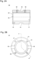
- Fig. 2A is a sectional view of the pump main shaft hub 60.
- Fig. 2B is a plan view of the end surface of the pump main shaft hub 60 that is brought into contact with the pump main shaft 80.
- the pump main shaft hub 60 is a tubular member into which the motor main shaft 22 can be inserted.
- the pump main shaft hub 60 is configured such that the pump main shaft hub 60 is coupled to the motor main shaft 22 via transition fitting when the pump main shaft hub 60 is fitted to the motor main shaft 22.
- the transition fitting means fitting that creates either a gap or a fastening margin between a hole and a shaft when the shaft is fitted into the hole.
- the transition fitting means fitting in a case in which a maximum allowable dimension of the shaft is greater than a minimum allowable dimension of the hole and a minimum allowable dimension of the shaft is smaller than a maximum allowable dimension of the hole.
- the pump main shaft hub 60 has a through-hole 61 into which the motor main shaft 22 is inserted. Also, as illustrated in Fig. 2B , the pump main shaft hub 60 has a key groove 67 in an inner surface thereof. When the pump main shaft hub 60 is fitted to the motor main shaft 22, a key formed in the motor main shaft 22, which is not illustrated, is inserted into the key groove 67 in the pump main shaft hub 60. In this manner, a drive force of the motor main shaft 22 in a rotation direction is delivered to the pump main shaft hub 60.
- an end surface 63 of the pump main shaft hub 60 that abuts on the pump main shaft 80 has holes 66 for securing the stud bolts 70 illustrated in Fig. 1 .
- the holes 66 extend substantially in parallel to the through-hole 61 into which the motor main shaft 22 is inserted.
- the stud bolts 70 secured to the holes 66 are disposed so as to extend substantially in parallel to the pump main shaft 80 and the motor main shaft 22 as illustrated in Fig. 1 .
- four holes 66 are provided at equal intervals in the example illustrated in Fig. 2B , the present invention is not limited thereto, and the number of holes 66 that can be provided is any number which is one or more. Note that in Fig.
- a notch portion 62 is formed in the end surface 63. Although the notch portion 62 extends from an inner peripheral surface to an outer peripheral surface of the pump main shaft hub 60 in the embodiment, the present invention is not limited thereto, and it is only necessary for the notch portion 62 to reach at least the outer peripheral surface.
- a locked portion 64 with a recessed shape is formed in the outer peripheral surface of the pump main shaft hub 60.
- the locked portion 64 is configured such that the locking portion of the pulley removing device is engaged therewith when the pump main shaft hub 60 is pulled out of the motor main shaft 22 as will be described later.
- the locked portion 64 can have any shape with which the locking portion of the pulley removing device can be engaged and may have a recessed shape as illustrated in Fig. 2A , for example, or may have a projecting shape.
- the pump main shaft hub 60 has a hole 65 into which the screw 72 (see Fig.
- Fig. 3A is a side view of the pump main shaft 80.
- Fig. 3B is a plan view of the end surface of the pump main shaft 80 that abuts on the end surface 63 of the pump main shaft hub 60.
- the pump main shaft 80 has a flange portion 81, a large diameter portion 82, a small diameter portion 83, and a bolt attachment portion 84.
- the flange portion 81 has an end surface 88 that abuts on the end surface 63 of the pump main shaft hub 60 illustrated in Figs. 2A and 2B .
- Fig. 1 is a side view of the pump main shaft 80.
- Fig. 3B is a plan view of the end surface of the pump main shaft 80 that abuts on the end surface 63 of the pump main shaft hub 60.
- the pump main shaft 80 has a flange portion 81, a large diameter portion 82, a small diameter portion 83, and a bolt attachment portion 84.
- the end surface 88 has holes 89 through which the stud bolts 70 secured to the pump main shaft hub 60 pass.
- the pump main shaft 80 and the motor main shaft 22 are coupled via the pup main shaft hub 60 by fastening the nuts 71 in a state in which the stud bolts 70 secured to the pump main shaft hub 60 pass through the holes 89 in the flange portion 81 of the pump main shaft 80.
- the large diameter portion 82 is a portion that extends from the flange portion 81 and passes through the opening 44a in the casing cover 44 as illustrated in Fig. 1 .
- the mechanical seal 48 is located at an outer periphery of the large diameter portion 82 and applies sealing between the opening 44a of the casing cover 44 and the large diameter portion 82 of the pump main shaft 80.
- the small diameter portion 83 extends from the large diameter portion 82 and has a smaller outer diameter than the outer diameter of the large diameter portion 82.
- a key groove 85 is formed in an outer peripheral surface of the small diameter portion 83.
- the bolt attachment portion 84 is a portion that extends from the small diameter portion 83 and is located at the furthest end and has a smaller outer diameter than the outer diameter of the small diameter portion 83.
- a screw groove 86 is formed in an outer peripheral surface of the bolt attachment portion 84, and the impeller 46 is prevented from dropping out of the pump main shaft 80 by screwing the blade stopper nut 51 illustrated in Fig. 1 into the screw groove 86 in a state in which the impeller 46 is attached to the small diameter portion 83.
- the pump main shaft hub 60 is coupled to the motor main shaft 22 via transition fitting in the embodiment. Therefore, it is possible to pull the pump main shaft hub 60 out of the motor main shaft 22 using a pulley removing device and to reduce the clearance between the pump main shaft hub 60 and the motor main shaft 22.
- the pump main shaft 80 and the impeller 46 connected to the pump main shaft hub 60 also similarly deviate from the axial center of the motor main shaft, and as a result, there is a concern that the impeller 46 comes into contact with the liner ring 50.
- the inner diameter of the liner ring 50 increases, the clearance between the liner ring 50 and the impeller 46 increases, the amount of a fluid flowing from the clearance to the low-pressure side thus increases, and pump efficiency is degraded.
- the pump main shaft hub 60 is coupled to the motor main shaft 22 via transition fitting, it is possible to reduce the deviation between the axial centers of the pump main shaft hub 60 and the motor main shaft, and as a result, it is possible to prevent the contact between the liner ring 50 and the impeller 46, and it is not necessary to increase the inner diameter of the liner ring 50.
- the pump device 10 according to the embodiment can curb the degradation of pump efficiency as compared with a case in which the pump main shaft hub 60 can easily be pulled out (with a hand, for example) out of the motor main shaft 22.
- the motor 20 and the pump 40 may be disassembled when the motor 20 is replaced, when maintenance for a bearing of the motor 20 is carried out, when maintenance for the pump device 10 is carried out, and the like.
- the pump main shaft 80 is secured to the pump main shaft hub 60 by fastening the nuts 71 to the stud bolts 70 secured to the pump main shaft hub 60. Therefore, it is possible to separate the pump main shaft 80 from the pump main shaft hub 60 by detaching the nuts 71 from the stud bolts 70 when the motor 20 and the pump 40 are disassembled.
- the pump main shaft 80 is secured to the pump main shaft hub 60 with a hexagon bolt instead of the stud bolts 70 and the nuts 71.
- a hexagon bolt instead of the stud bolts 70 and the nuts 71.
- a space that is larger in the axial direction than a pulling margin for detaching the nuts 71 from the stud bolts 70 (the length of exposed portions of the stud bolts 70 and the length of the nuts 71) is required.
- the motor 20 is pulled out of the pump main shaft hub 60 with the pump main shaft 80 and the pump main shaft hub 60 coupled to each other, in order to separate the pump 40 from the motor 20 in the case in which the pump main shaft 80 is secured to the pump main shaft hub 60 with the hexagon bolt.
- a nut 53 coupling the bracket 49 to the motor 20 and the screw 72 are detached, and the motor 20 is pulled out of the pump main shaft hub 60.
- a pulley removing device cannot be used in this case, it is necessary to couple the motor main shaft 22 to the pump main shaft hub 60 with clearance fitting rather than transition fitting, in order to pull the motor 20 out of the pump main shaft hub 60.
- the bracket 49 has the opening 52 for detaching the nuts 71 from the stud bolts 70. Specifically, it is possible to insert a tool into the opening 52 and thereby to detach the nuts 71 without disassembling the bracket 49 from the pump 40 and the motor 20. As a result, it is possible to detach the nuts 71 from the stud bolts 70 and to detach the pump main shaft 80 from the pump main shaft hub 60. Also, since the opening 52 is provided closer to the mechanical seal 48 than to the motor 20 in the axial direction of the pump main shaft 80, the opening 52 can be used as a window for inspecting the mechanical seal 48.
- the pump main shaft hub 60 has, in the outer peripheral surface thereof, the locked portion 64 engaged with the locking portion of the pulley removing device. Therefore, it is possible to pull the pump main shaft hub 60 out of the motor main shaft 22 using the pulley removing device after detaching the pump main shaft 80 from the pump main shaft hub 60.
- the pump main shaft hub 60 has the notch portion 62 extending up to the outer peripheral surface in the end surface 63 that abuts on the flange portion 81 of the pump main shaft 80. In this manner, it is possible to easily separate the pump main shaft 80 from the pump main shaft hub 60 by inserting a tool such as a flathead screwdriver into the notch portion 62 when the pump main shaft 80 is detached from the pump main shaft hub 60.
- the pump main shaft 80 is detached from the pump main shaft hub 60 (first process). Specifically, the protection plate attached to the opening 52 of the bracket 49, which is not illustrated, is detached, and the nuts 71 are detached from the stud bolts 70 through the opening 52. Then, a tool such as a flathead screwdriver is inserted into the notch portion 62 formed in the end surface 63 of the pump main shaft hub 60 to separate the pump main shaft 80 from the pump main shaft hub 60.
- the pump main shaft hub 60 is pulled out of the motor main shaft 22 (second process). Specifically, the nut 53 connecting the bracket 49 to the motor 20 is detached, and the motor 20 is pulled out of the pump 40 along with the pump main shaft hub 60. Thereafter, the screw 72 is detached from the pump main shaft hub 60. Next, the locking portion of the pulley removing device is engaged with the locked portion 64 formed in the outer peripheral surface of the pump main shaft hub 60, and the pump main shaft hub 60 is pulled out of the motor main shaft 22. At this time, the pump main shaft hub 60 is preferably heated with a burner or the like. In this manner, it is possible to easily detach the motor 20 from the pump 40.
Landscapes
- Engineering & Computer Science (AREA)
- General Engineering & Computer Science (AREA)
- Mechanical Engineering (AREA)
- Structures Of Non-Positive Displacement Pumps (AREA)
Claims (10)
- Pompe (40) comprenant :une roue (46) ;un arbre principal de pompe (80) auquel la roue (46) est fixée ; etun moyeu d'arbre principal de pompe (60) qui est fixé de manière amovible à une extrémité de l'arbre principal de pompe (80),dans laquelle le moyeu d'arbre principal de pompe (60) est un élément tubulaire dans lequel un arbre principal de moteur (22) peut être inséré, la pompe étant caractérisée par le fait que le moyeu d'arbre principal de pompe (60) est configuré pour être couplé à l'arbre principal de moteur (22) par un raccord de transition ; etdans laquelle le moyeu d'arbre principal de pompe (60) comporte, dans une surface périphérique externe, une partie verrouillée (64) configurée pour être en prise avec une partie de verrouillage d'un dispositif de retrait de poulie.
- Pompe (40) selon la revendication 1, dans laquellel'arbre principal de pompe (80) a une partie de bride (81) à l'extrémité,la pompe (40) comprend en outre un goujon (70) et un écrou (70) pour fixer de manière amovible une surface d'extrémité (63) du moyeu d'arbre principal de pompe (60) à la partie de bride (81) de l'arbre principal de pompe (80), etla surface d'extrémité (63) du moyeu d'arbre principal de pompe (60) comporte un trou (66) pour fixer le goujon (70) .
- Pompe (40) selon la revendication 2, comprenant :un carter (41) et un couvercle de carter (44) configurés pour accueillir la roue (46) ; etun support (49) configuré pour coupler le couvercle de carter (44) à un moteur (20) et pour loger intérieurement le moyeu d'arbre principal de pompe (60),dans lequel le support (49) possède une ouverture (52) pour détacher l'écrou (70) du goujon (70).
- Pompe (40) selon la revendication 3, dans laquellele couvercle de carter (44) a une ouverture (44a) à travers laquelle passe l'arbre principal de pompe (80),la pompe (40) comporte en outre un mécanisme d'étanchéité (48) configuré pour assurer l'étanchéité entre l'arbre principal de pompe (80) et le couvercle de carter (44), etl'ouverture (52) est prévue plus proche du mécanisme d'étanchéité (48) que du moteur (20) dans une direction axiale de l'arbre principal de pompe (80).
- Pompe (40) selon l'une quelconque des revendications 1 à 4, dans laquellel'arbre principal de pompe (80) a une partie de bride (81) à l'extrémité, etle moyeu d'arbre principal de pompe (60) à, dans une surface d'extrémité (88) qui vient en butée contre la partie de bride (81) de l'arbre principal de pompe (80), une partie d'encoche (62) qui s'étend jusqu'à la surface périphérique externe.
- Dispositif de pompe (10) comprenant :la pompe (40) selon l'une quelconque des revendications 1 à 5 ; etun moteur (20) dont l'arbre principal (22) est couplé au moyeu d'arbre principal de pompe (60) de la pompe (40) par un raccord de transition.
- Procédé de démontage d'un dispositif de pompe (10) dans lequel un arbre principal de pompe (80) et un arbre principal de moteur (22) sont reliés par un moyeu d'arbre principal de pompe (60) monté en transition sur l'arbre principal de moteur (22), le procédé comprenant :un premier processus de détachement de l'arbre principal de pompe (80) du moyeu d'arbre principal de pompe (60) ; etun deuxième processus d'extraction du moyeu d'arbre principal de pompe (60) hors de l'arbre principal de moteur (22) après le premier processus,dans lequel le deuxième processus comprend :la mise en prise d'une partie de verrouillage d'un dispositif de retrait de poulie avec une partie verrouillée (64) formée dans une surface périphérique externe du moyeu d'arbre principal de pompe (60) ; etla traction du moyeu d'arbre principal de pompe (60) hors de l'arbre principal de moteur (22).
- Procédé de démontage d'un dispositif de pompe (10) selon la revendication 7,
dans lequel le premier processus comprend un processus de détachement d'un écrou (70) vissé sur un goujon (70) fixé au moyeu d'arbre principal de pompe (60). - Procédé de démontage d'un dispositif de pompe (10) selon la revendication 8,
dans lequel le processus de détachement de l'écrou (70) comprend le couplage d'un couvercle de carter (44) à un moteur (20) et le détachement de l'écrou (70) à travers une ouverture (52) formée dans un support (49) qui loge intérieurement le moyeu d'arbre principal de pompe (60). - Procédé de démontage d'un dispositif de pompe (10) selon l'une quelconque des revendications 7 à 9,
dans lequel le premier processus comprend l'insertion d'un outil dans une partie d'encoche (62) formée dans une surface d'extrémité (63) du moyeu d'arbre principal de pompe (60) qui vient en butée contre une partie de bride (81) de l'arbre principal de pompe (80), et la séparation de la partie de bride (81) de l'arbre principal de pompe (80) du moyeu d'arbre principal de pompe (60).
Applications Claiming Priority (2)
| Application Number | Priority Date | Filing Date | Title |
|---|---|---|---|
| JP2017203632A JP6949657B2 (ja) | 2017-10-20 | 2017-10-20 | ポンプ、ポンプ装置、及びポンプ装置の分解方法 |
| PCT/JP2018/038912 WO2019078316A1 (fr) | 2017-10-20 | 2018-10-19 | Pompe, dispositif de type pompe et procédé de démontage de dispositif de type pompe |
Publications (3)
| Publication Number | Publication Date |
|---|---|
| EP3699435A1 EP3699435A1 (fr) | 2020-08-26 |
| EP3699435A4 EP3699435A4 (fr) | 2021-07-14 |
| EP3699435B1 true EP3699435B1 (fr) | 2023-09-13 |
Family
ID=66173740
Family Applications (1)
| Application Number | Title | Priority Date | Filing Date |
|---|---|---|---|
| EP18868678.6A Active EP3699435B1 (fr) | 2017-10-20 | 2018-10-19 | Pompe, dispositif de type pompe et procédé de démontage de dispositif de type pompe |
Country Status (6)
| Country | Link |
|---|---|
| EP (1) | EP3699435B1 (fr) |
| JP (1) | JP6949657B2 (fr) |
| CN (1) | CN111226043A (fr) |
| AU (1) | AU2018353673B2 (fr) |
| ES (1) | ES2963338T3 (fr) |
| WO (1) | WO2019078316A1 (fr) |
Families Citing this family (1)
| Publication number | Priority date | Publication date | Assignee | Title |
|---|---|---|---|---|
| DE202019105336U1 (de) * | 2019-09-26 | 2021-01-05 | Evoguard Gmbh | Pumpenwelle mit Befestigungsbolzen |
Family Cites Families (15)
| Publication number | Priority date | Publication date | Assignee | Title |
|---|---|---|---|---|
| JPS4511746Y1 (fr) | 1966-10-26 | 1970-05-25 | ||
| JPS518600U (fr) * | 1974-07-08 | 1976-01-22 | ||
| JPS61116192U (fr) | 1984-12-29 | 1986-07-22 | ||
| JPH02243230A (ja) * | 1989-03-13 | 1990-09-27 | Toshiba Eng & Constr Co Ltd | 回転機のプーリ取り外し装置 |
| US5051071A (en) * | 1990-02-09 | 1991-09-24 | Haentjens Walter D | Heat dissipating coupling for rotary shafts |
| JPH0942193A (ja) * | 1995-07-27 | 1997-02-10 | Hitachi Ltd | 回転ポンプ及び回転羽根車固定方法 |
| JP4131597B2 (ja) * | 1999-05-24 | 2008-08-13 | 三菱重工業株式会社 | 抜取具 |
| CN2451786Y (zh) * | 2000-11-28 | 2001-10-03 | 何良贵 | 轴便拆式直联离心泵 |
| CN201149041Y (zh) * | 2008-01-25 | 2008-11-12 | 长沙天鹅工业泵股份有限公司 | 一种套筒联轴器及其拆卸工具 |
| RU2702823C2 (ru) * | 2014-10-01 | 2019-10-11 | ДжиИ ОЙЛ ЭНД ГЭС ЭСП, ИНК. | Соединение обжимной шайбой для валов наземного насоса, несущих осевую нагрузку |
| CN105508283A (zh) * | 2014-10-09 | 2016-04-20 | 株式会社荏原制作所 | 涡轮泵 |
| CN205047448U (zh) * | 2015-09-24 | 2016-02-24 | 山东壮发泵业有限公司 | 一种无轴承泵 |
| JP6590622B2 (ja) * | 2015-10-01 | 2019-10-16 | 株式会社荏原製作所 | ターボ形ポンプ |
| CN106762834A (zh) * | 2015-11-25 | 2017-05-31 | 天津市明奥泵业有限公司 | 新型带加强板的卧式管道泵 |
| US10280931B2 (en) * | 2016-01-27 | 2019-05-07 | Pentair Flow Technologies, Llc | Systems and methods for split coupled pump and jacking gland |
-
2017
- 2017-10-20 JP JP2017203632A patent/JP6949657B2/ja active Active
-
2018
- 2018-10-19 AU AU2018353673A patent/AU2018353673B2/en active Active
- 2018-10-19 EP EP18868678.6A patent/EP3699435B1/fr active Active
- 2018-10-19 CN CN201880067940.9A patent/CN111226043A/zh active Pending
- 2018-10-19 ES ES18868678T patent/ES2963338T3/es active Active
- 2018-10-19 WO PCT/JP2018/038912 patent/WO2019078316A1/fr not_active Ceased
Also Published As
| Publication number | Publication date |
|---|---|
| EP3699435A4 (fr) | 2021-07-14 |
| AU2018353673B2 (en) | 2024-05-23 |
| ES2963338T3 (es) | 2024-03-26 |
| CN111226043A (zh) | 2020-06-02 |
| JP6949657B2 (ja) | 2021-10-13 |
| EP3699435A1 (fr) | 2020-08-26 |
| JP2019078187A (ja) | 2019-05-23 |
| WO2019078316A1 (fr) | 2019-04-25 |
| AU2018353673A1 (en) | 2020-05-28 |
Similar Documents
| Publication | Publication Date | Title |
|---|---|---|
| US12023766B2 (en) | Hydraulic tensioning and release tool for expansion fasteners | |
| CN106994660A (zh) | 用于驱动轴叉衬套的更换工具 | |
| CN1282646A (zh) | 安装和拆卸滚轧机辊颈轴承用的液压驱动工具 | |
| CN103827507B (zh) | 连杆机构及具有该连杆机构的可变静翼驱动装置 | |
| US11389909B2 (en) | Method and tool for reconditioning a damaged thread | |
| JP2010261465A (ja) | 真空ポンプ用の分割継手およびそれを得る方法 | |
| EP3006741A1 (fr) | Turbopompe avec accouplement d'arbre | |
| EP3699435B1 (fr) | Pompe, dispositif de type pompe et procédé de démontage de dispositif de type pompe | |
| CN201291372Y (zh) | 液力拆装锥孔轴承装置 | |
| JPS6018852B2 (ja) | カプリング | |
| WO2017086345A1 (fr) | Accouplement d'arbres, et dispositif de pompe | |
| WO2016053333A1 (fr) | Liaison de frette pour arbres de support de poussée de pompe de surface. | |
| HK1222216A1 (zh) | 涡轮泵 | |
| AU2011282171B2 (en) | Improved impeller attachment method | |
| CN108080925B (zh) | 一种环形腔内滚子轴承外圈分解装置及方法 | |
| CN112196868B (zh) | 装配螺栓连接结构 | |
| CN115095606B (zh) | 一种联轴器、联轴结构及其拆装方法 | |
| RU2239731C2 (ru) | Легкосъемное крепежное соединение с радиальным натягом | |
| US4829718A (en) | Grinding wheel assembly and method | |
| CN213647396U (zh) | 一种拆卸工具 | |
| JP7105664B2 (ja) | 回転式流体機械 | |
| JP2021169776A (ja) | ポンプ装置およびポンプ装置の組み立て方法 | |
| CN117730211A (zh) | 安装拆卸组件、轴和轴承组件、安装方法及拆卸方法 | |
| CN121976969A (en) | Taper sleeve type impeller mounting shaft disc, impeller and fan comprising taper sleeve type impeller mounting shaft disc | |
| CN120095750A (zh) | 一种转子轴端螺母止动工装、装配及分解方法 |
Legal Events
| Date | Code | Title | Description |
|---|---|---|---|
| STAA | Information on the status of an ep patent application or granted ep patent |
Free format text: STATUS: THE INTERNATIONAL PUBLICATION HAS BEEN MADE |
|
| PUAI | Public reference made under article 153(3) epc to a published international application that has entered the european phase |
Free format text: ORIGINAL CODE: 0009012 |
|
| STAA | Information on the status of an ep patent application or granted ep patent |
Free format text: STATUS: REQUEST FOR EXAMINATION WAS MADE |
|
| 17P | Request for examination filed |
Effective date: 20200508 |
|
| AK | Designated contracting states |
Kind code of ref document: A1 Designated state(s): AL AT BE BG CH CY CZ DE DK EE ES FI FR GB GR HR HU IE IS IT LI LT LU LV MC MK MT NL NO PL PT RO RS SE SI SK SM TR |
|
| AX | Request for extension of the european patent |
Extension state: BA ME |
|
| DAV | Request for validation of the european patent (deleted) | ||
| DAX | Request for extension of the european patent (deleted) | ||
| REG | Reference to a national code |
Ref country code: DE Free format text: PREVIOUS MAIN CLASS: F04D0029044000 Ref country code: DE Ref legal event code: R079 Ref document number: 602018057682 Country of ref document: DE Free format text: PREVIOUS MAIN CLASS: F04D0029044000 Ipc: F04D0013020000 |
|
| A4 | Supplementary search report drawn up and despatched |
Effective date: 20210611 |
|
| RIC1 | Information provided on ipc code assigned before grant |
Ipc: F04D 13/02 20060101AFI20210607BHEP Ipc: F04D 29/62 20060101ALI20210607BHEP Ipc: F04D 13/06 20060101ALI20210607BHEP Ipc: F16D 1/076 20060101ALI20210607BHEP |
|
| GRAP | Despatch of communication of intention to grant a patent |
Free format text: ORIGINAL CODE: EPIDOSNIGR1 |
|
| STAA | Information on the status of an ep patent application or granted ep patent |
Free format text: STATUS: GRANT OF PATENT IS INTENDED |
|
| INTG | Intention to grant announced |
Effective date: 20230330 |
|
| GRAS | Grant fee paid |
Free format text: ORIGINAL CODE: EPIDOSNIGR3 |
|
| RAP3 | Party data changed (applicant data changed or rights of an application transferred) |
Owner name: EBARA CORPORATION |
|
| GRAA | (expected) grant |
Free format text: ORIGINAL CODE: 0009210 |
|
| STAA | Information on the status of an ep patent application or granted ep patent |
Free format text: STATUS: THE PATENT HAS BEEN GRANTED |
|
| AK | Designated contracting states |
Kind code of ref document: B1 Designated state(s): AL AT BE BG CH CY CZ DE DK EE ES FI FR GB GR HR HU IE IS IT LI LT LU LV MC MK MT NL NO PL PT RO RS SE SI SK SM TR |
|
| P01 | Opt-out of the competence of the unified patent court (upc) registered |
Effective date: 20230807 |
|
| REG | Reference to a national code |
Ref country code: CH Ref legal event code: EP |
|
| REG | Reference to a national code |
Ref country code: DE Ref legal event code: R096 Ref document number: 602018057682 Country of ref document: DE |
|
| REG | Reference to a national code |
Ref country code: IE Ref legal event code: FG4D |
|
| REG | Reference to a national code |
Ref country code: LT Ref legal event code: MG9D |
|
| REG | Reference to a national code |
Ref country code: NL Ref legal event code: MP Effective date: 20230913 |
|
| PG25 | Lapsed in a contracting state [announced via postgrant information from national office to epo] |
Ref country code: GR Free format text: LAPSE BECAUSE OF FAILURE TO SUBMIT A TRANSLATION OF THE DESCRIPTION OR TO PAY THE FEE WITHIN THE PRESCRIBED TIME-LIMIT Effective date: 20231214 |
|
| PG25 | Lapsed in a contracting state [announced via postgrant information from national office to epo] |
Ref country code: SE Free format text: LAPSE BECAUSE OF FAILURE TO SUBMIT A TRANSLATION OF THE DESCRIPTION OR TO PAY THE FEE WITHIN THE PRESCRIBED TIME-LIMIT Effective date: 20230913 Ref country code: RS Free format text: LAPSE BECAUSE OF FAILURE TO SUBMIT A TRANSLATION OF THE DESCRIPTION OR TO PAY THE FEE WITHIN THE PRESCRIBED TIME-LIMIT Effective date: 20230913 Ref country code: NO Free format text: LAPSE BECAUSE OF FAILURE TO SUBMIT A TRANSLATION OF THE DESCRIPTION OR TO PAY THE FEE WITHIN THE PRESCRIBED TIME-LIMIT Effective date: 20231213 Ref country code: LV Free format text: LAPSE BECAUSE OF FAILURE TO SUBMIT A TRANSLATION OF THE DESCRIPTION OR TO PAY THE FEE WITHIN THE PRESCRIBED TIME-LIMIT Effective date: 20230913 Ref country code: LT Free format text: LAPSE BECAUSE OF FAILURE TO SUBMIT A TRANSLATION OF THE DESCRIPTION OR TO PAY THE FEE WITHIN THE PRESCRIBED TIME-LIMIT Effective date: 20230913 Ref country code: HR Free format text: LAPSE BECAUSE OF FAILURE TO SUBMIT A TRANSLATION OF THE DESCRIPTION OR TO PAY THE FEE WITHIN THE PRESCRIBED TIME-LIMIT Effective date: 20230913 Ref country code: GR Free format text: LAPSE BECAUSE OF FAILURE TO SUBMIT A TRANSLATION OF THE DESCRIPTION OR TO PAY THE FEE WITHIN THE PRESCRIBED TIME-LIMIT Effective date: 20231214 Ref country code: FI Free format text: LAPSE BECAUSE OF FAILURE TO SUBMIT A TRANSLATION OF THE DESCRIPTION OR TO PAY THE FEE WITHIN THE PRESCRIBED TIME-LIMIT Effective date: 20230913 |
|
| REG | Reference to a national code |
Ref country code: AT Ref legal event code: MK05 Ref document number: 1611554 Country of ref document: AT Kind code of ref document: T Effective date: 20230913 |
|
| PG25 | Lapsed in a contracting state [announced via postgrant information from national office to epo] |
Ref country code: NL Free format text: LAPSE BECAUSE OF FAILURE TO SUBMIT A TRANSLATION OF THE DESCRIPTION OR TO PAY THE FEE WITHIN THE PRESCRIBED TIME-LIMIT Effective date: 20230913 |
|
| REG | Reference to a national code |
Ref country code: ES Ref legal event code: FG2A Ref document number: 2963338 Country of ref document: ES Kind code of ref document: T3 Effective date: 20240326 |
|
| PG25 | Lapsed in a contracting state [announced via postgrant information from national office to epo] |
Ref country code: IS Free format text: LAPSE BECAUSE OF FAILURE TO SUBMIT A TRANSLATION OF THE DESCRIPTION OR TO PAY THE FEE WITHIN THE PRESCRIBED TIME-LIMIT Effective date: 20240113 |
|
| PG25 | Lapsed in a contracting state [announced via postgrant information from national office to epo] |
Ref country code: AT Free format text: LAPSE BECAUSE OF FAILURE TO SUBMIT A TRANSLATION OF THE DESCRIPTION OR TO PAY THE FEE WITHIN THE PRESCRIBED TIME-LIMIT Effective date: 20230913 |
|
| PG25 | Lapsed in a contracting state [announced via postgrant information from national office to epo] |
Ref country code: SM Free format text: LAPSE BECAUSE OF FAILURE TO SUBMIT A TRANSLATION OF THE DESCRIPTION OR TO PAY THE FEE WITHIN THE PRESCRIBED TIME-LIMIT Effective date: 20230913 Ref country code: RO Free format text: LAPSE BECAUSE OF FAILURE TO SUBMIT A TRANSLATION OF THE DESCRIPTION OR TO PAY THE FEE WITHIN THE PRESCRIBED TIME-LIMIT Effective date: 20230913 Ref country code: IS Free format text: LAPSE BECAUSE OF FAILURE TO SUBMIT A TRANSLATION OF THE DESCRIPTION OR TO PAY THE FEE WITHIN THE PRESCRIBED TIME-LIMIT Effective date: 20240113 Ref country code: EE Free format text: LAPSE BECAUSE OF FAILURE TO SUBMIT A TRANSLATION OF THE DESCRIPTION OR TO PAY THE FEE WITHIN THE PRESCRIBED TIME-LIMIT Effective date: 20230913 Ref country code: CZ Free format text: LAPSE BECAUSE OF FAILURE TO SUBMIT A TRANSLATION OF THE DESCRIPTION OR TO PAY THE FEE WITHIN THE PRESCRIBED TIME-LIMIT Effective date: 20230913 Ref country code: AT Free format text: LAPSE BECAUSE OF FAILURE TO SUBMIT A TRANSLATION OF THE DESCRIPTION OR TO PAY THE FEE WITHIN THE PRESCRIBED TIME-LIMIT Effective date: 20230913 Ref country code: SK Free format text: LAPSE BECAUSE OF FAILURE TO SUBMIT A TRANSLATION OF THE DESCRIPTION OR TO PAY THE FEE WITHIN THE PRESCRIBED TIME-LIMIT Effective date: 20230913 Ref country code: PT Free format text: LAPSE BECAUSE OF FAILURE TO SUBMIT A TRANSLATION OF THE DESCRIPTION OR TO PAY THE FEE WITHIN THE PRESCRIBED TIME-LIMIT Effective date: 20240115 |
|
| REG | Reference to a national code |
Ref country code: DE Ref legal event code: R119 Ref document number: 602018057682 Country of ref document: DE |
|
| PG25 | Lapsed in a contracting state [announced via postgrant information from national office to epo] |
Ref country code: PL Free format text: LAPSE BECAUSE OF FAILURE TO SUBMIT A TRANSLATION OF THE DESCRIPTION OR TO PAY THE FEE WITHIN THE PRESCRIBED TIME-LIMIT Effective date: 20230913 |
|
| REG | Reference to a national code |
Ref country code: CH Ref legal event code: PL |
|
| REG | Reference to a national code |
Ref country code: BE Ref legal event code: MM Effective date: 20231031 |
|
| PG25 | Lapsed in a contracting state [announced via postgrant information from national office to epo] |
Ref country code: LU Free format text: LAPSE BECAUSE OF NON-PAYMENT OF DUE FEES Effective date: 20231019 |
|
| PG25 | Lapsed in a contracting state [announced via postgrant information from national office to epo] |
Ref country code: LU Free format text: LAPSE BECAUSE OF NON-PAYMENT OF DUE FEES Effective date: 20231019 |
|
| PG25 | Lapsed in a contracting state [announced via postgrant information from national office to epo] |
Ref country code: MC Free format text: LAPSE BECAUSE OF FAILURE TO SUBMIT A TRANSLATION OF THE DESCRIPTION OR TO PAY THE FEE WITHIN THE PRESCRIBED TIME-LIMIT Effective date: 20230913 |
|
| PG25 | Lapsed in a contracting state [announced via postgrant information from national office to epo] |
Ref country code: DK Free format text: LAPSE BECAUSE OF FAILURE TO SUBMIT A TRANSLATION OF THE DESCRIPTION OR TO PAY THE FEE WITHIN THE PRESCRIBED TIME-LIMIT Effective date: 20230913 |
|
| PG25 | Lapsed in a contracting state [announced via postgrant information from national office to epo] |
Ref country code: CH Free format text: LAPSE BECAUSE OF NON-PAYMENT OF DUE FEES Effective date: 20231031 |
|
| PLBE | No opposition filed within time limit |
Free format text: ORIGINAL CODE: 0009261 |
|
| STAA | Information on the status of an ep patent application or granted ep patent |
Free format text: STATUS: NO OPPOSITION FILED WITHIN TIME LIMIT |
|
| PG25 | Lapsed in a contracting state [announced via postgrant information from national office to epo] |
Ref country code: MC Free format text: LAPSE BECAUSE OF FAILURE TO SUBMIT A TRANSLATION OF THE DESCRIPTION OR TO PAY THE FEE WITHIN THE PRESCRIBED TIME-LIMIT Effective date: 20230913 Ref country code: DK Free format text: LAPSE BECAUSE OF FAILURE TO SUBMIT A TRANSLATION OF THE DESCRIPTION OR TO PAY THE FEE WITHIN THE PRESCRIBED TIME-LIMIT Effective date: 20230913 Ref country code: DE Free format text: LAPSE BECAUSE OF NON-PAYMENT OF DUE FEES Effective date: 20240501 Ref country code: CH Free format text: LAPSE BECAUSE OF NON-PAYMENT OF DUE FEES Effective date: 20231031 |
|
| 26N | No opposition filed |
Effective date: 20240614 |
|
| GBPC | Gb: european patent ceased through non-payment of renewal fee |
Effective date: 20231213 |
|
| PG25 | Lapsed in a contracting state [announced via postgrant information from national office to epo] |
Ref country code: BE Free format text: LAPSE BECAUSE OF NON-PAYMENT OF DUE FEES Effective date: 20231031 |
|
| PG25 | Lapsed in a contracting state [announced via postgrant information from national office to epo] |
Ref country code: IE Free format text: LAPSE BECAUSE OF NON-PAYMENT OF DUE FEES Effective date: 20231019 |
|
| PG25 | Lapsed in a contracting state [announced via postgrant information from national office to epo] |
Ref country code: GB Free format text: LAPSE BECAUSE OF NON-PAYMENT OF DUE FEES Effective date: 20231213 |
|
| PG25 | Lapsed in a contracting state [announced via postgrant information from national office to epo] |
Ref country code: FR Free format text: LAPSE BECAUSE OF NON-PAYMENT OF DUE FEES Effective date: 20231113 |
|
| PG25 | Lapsed in a contracting state [announced via postgrant information from national office to epo] |
Ref country code: SI Free format text: LAPSE BECAUSE OF FAILURE TO SUBMIT A TRANSLATION OF THE DESCRIPTION OR TO PAY THE FEE WITHIN THE PRESCRIBED TIME-LIMIT Effective date: 20230913 |
|
| PG25 | Lapsed in a contracting state [announced via postgrant information from national office to epo] |
Ref country code: SI Free format text: LAPSE BECAUSE OF FAILURE TO SUBMIT A TRANSLATION OF THE DESCRIPTION OR TO PAY THE FEE WITHIN THE PRESCRIBED TIME-LIMIT Effective date: 20230913 Ref country code: IE Free format text: LAPSE BECAUSE OF NON-PAYMENT OF DUE FEES Effective date: 20231019 Ref country code: GB Free format text: LAPSE BECAUSE OF NON-PAYMENT OF DUE FEES Effective date: 20231213 Ref country code: FR Free format text: LAPSE BECAUSE OF NON-PAYMENT OF DUE FEES Effective date: 20231113 |
|
| PG25 | Lapsed in a contracting state [announced via postgrant information from national office to epo] |
Ref country code: BG Free format text: LAPSE BECAUSE OF FAILURE TO SUBMIT A TRANSLATION OF THE DESCRIPTION OR TO PAY THE FEE WITHIN THE PRESCRIBED TIME-LIMIT Effective date: 20230913 |
|
| PG25 | Lapsed in a contracting state [announced via postgrant information from national office to epo] |
Ref country code: BG Free format text: LAPSE BECAUSE OF FAILURE TO SUBMIT A TRANSLATION OF THE DESCRIPTION OR TO PAY THE FEE WITHIN THE PRESCRIBED TIME-LIMIT Effective date: 20230913 |
|
| PG25 | Lapsed in a contracting state [announced via postgrant information from national office to epo] |
Ref country code: CY Free format text: LAPSE BECAUSE OF FAILURE TO SUBMIT A TRANSLATION OF THE DESCRIPTION OR TO PAY THE FEE WITHIN THE PRESCRIBED TIME-LIMIT; INVALID AB INITIO Effective date: 20181019 |
|
| PG25 | Lapsed in a contracting state [announced via postgrant information from national office to epo] |
Ref country code: HU Free format text: LAPSE BECAUSE OF FAILURE TO SUBMIT A TRANSLATION OF THE DESCRIPTION OR TO PAY THE FEE WITHIN THE PRESCRIBED TIME-LIMIT; INVALID AB INITIO Effective date: 20181019 |
|
| PGFP | Annual fee paid to national office [announced via postgrant information from national office to epo] |
Ref country code: IT Payment date: 20250922 Year of fee payment: 8 |
|
| PG25 | Lapsed in a contracting state [announced via postgrant information from national office to epo] |
Ref country code: TR Free format text: LAPSE BECAUSE OF FAILURE TO SUBMIT A TRANSLATION OF THE DESCRIPTION OR TO PAY THE FEE WITHIN THE PRESCRIBED TIME-LIMIT Effective date: 20230913 |
|
| PGFP | Annual fee paid to national office [announced via postgrant information from national office to epo] |
Ref country code: ES Payment date: 20251103 Year of fee payment: 8 |