EP3699448A1 - Regelungsvorrichtung für drehmomentbegrenzer - Google Patents
Regelungsvorrichtung für drehmomentbegrenzer Download PDFInfo
- Publication number
- EP3699448A1 EP3699448A1 EP19159100.7A EP19159100A EP3699448A1 EP 3699448 A1 EP3699448 A1 EP 3699448A1 EP 19159100 A EP19159100 A EP 19159100A EP 3699448 A1 EP3699448 A1 EP 3699448A1
- Authority
- EP
- European Patent Office
- Prior art keywords
- nut
- torque limiter
- torque
- drive member
- notches
- Prior art date
- Legal status (The legal status is an assumption and is not a legal conclusion. Google has not performed a legal analysis and makes no representation as to the accuracy of the status listed.)
- Withdrawn
Links
Images


Classifications
-
- F—MECHANICAL ENGINEERING; LIGHTING; HEATING; WEAPONS; BLASTING
- F16—ENGINEERING ELEMENTS AND UNITS; GENERAL MEASURES FOR PRODUCING AND MAINTAINING EFFECTIVE FUNCTIONING OF MACHINES OR INSTALLATIONS; THERMAL INSULATION IN GENERAL
- F16D—COUPLINGS FOR TRANSMITTING ROTATION; CLUTCHES; BRAKES
- F16D7/00—Slip couplings, e.g. slipping on overload, for absorbing shock
- F16D7/04—Slip couplings, e.g. slipping on overload, for absorbing shock of the ratchet type
- F16D7/042—Slip couplings, e.g. slipping on overload, for absorbing shock of the ratchet type with at least one part moving axially between engagement and disengagement
- F16D7/044—Slip couplings, e.g. slipping on overload, for absorbing shock of the ratchet type with at least one part moving axially between engagement and disengagement the axially moving part being coaxial with the rotation, e.g. a gear with face teeth
-
- F—MECHANICAL ENGINEERING; LIGHTING; HEATING; WEAPONS; BLASTING
- F16—ENGINEERING ELEMENTS AND UNITS; GENERAL MEASURES FOR PRODUCING AND MAINTAINING EFFECTIVE FUNCTIONING OF MACHINES OR INSTALLATIONS; THERMAL INSULATION IN GENERAL
- F16D—COUPLINGS FOR TRANSMITTING ROTATION; CLUTCHES; BRAKES
- F16D7/00—Slip couplings, e.g. slipping on overload, for absorbing shock
- F16D7/04—Slip couplings, e.g. slipping on overload, for absorbing shock of the ratchet type
- F16D7/06—Slip couplings, e.g. slipping on overload, for absorbing shock of the ratchet type with intermediate balls or rollers
- F16D7/10—Slip couplings, e.g. slipping on overload, for absorbing shock of the ratchet type with intermediate balls or rollers moving radially between engagement and disengagement
-
- F—MECHANICAL ENGINEERING; LIGHTING; HEATING; WEAPONS; BLASTING
- F16—ENGINEERING ELEMENTS AND UNITS; GENERAL MEASURES FOR PRODUCING AND MAINTAINING EFFECTIVE FUNCTIONING OF MACHINES OR INSTALLATIONS; THERMAL INSULATION IN GENERAL
- F16D—COUPLINGS FOR TRANSMITTING ROTATION; CLUTCHES; BRAKES
- F16D43/00—Automatic clutches
- F16D43/02—Automatic clutches actuated entirely mechanically
- F16D43/20—Automatic clutches actuated entirely mechanically controlled by torque, e.g. overload-release clutches, slip-clutches with means by which torque varies the clutching pressure
- F16D43/202—Automatic clutches actuated entirely mechanically controlled by torque, e.g. overload-release clutches, slip-clutches with means by which torque varies the clutching pressure of the ratchet type
- F16D43/2022—Automatic clutches actuated entirely mechanically controlled by torque, e.g. overload-release clutches, slip-clutches with means by which torque varies the clutching pressure of the ratchet type with at least one part moving axially between engagement and disengagement
- F16D43/2024—Automatic clutches actuated entirely mechanically controlled by torque, e.g. overload-release clutches, slip-clutches with means by which torque varies the clutching pressure of the ratchet type with at least one part moving axially between engagement and disengagement the axially moving part being coaxial with the rotation, e.g. a gear with face teeth
-
- F—MECHANICAL ENGINEERING; LIGHTING; HEATING; WEAPONS; BLASTING
- F16—ENGINEERING ELEMENTS AND UNITS; GENERAL MEASURES FOR PRODUCING AND MAINTAINING EFFECTIVE FUNCTIONING OF MACHINES OR INSTALLATIONS; THERMAL INSULATION IN GENERAL
- F16D—COUPLINGS FOR TRANSMITTING ROTATION; CLUTCHES; BRAKES
- F16D59/00—Self-acting brakes, e.g. coming into operation at a predetermined speed
-
- B—PERFORMING OPERATIONS; TRANSPORTING
- B25—HAND TOOLS; PORTABLE POWER-DRIVEN TOOLS; MANIPULATORS
- B25B—TOOLS OR BENCH DEVICES NOT OTHERWISE PROVIDED FOR, FOR FASTENING, CONNECTING, DISENGAGING, OR HOLDING
- B25B23/00—Details of, or accessories for, spanners, wrenches, screwdrivers
- B25B23/14—Arrangement of torque limiters or torque indicators in wrenches or screwdrivers
- B25B23/142—Arrangement of torque limiters or torque indicators in wrenches or screwdrivers specially adapted for hand operated wrenches or screwdrivers
- B25B23/1422—Arrangement of torque limiters or torque indicators in wrenches or screwdrivers specially adapted for hand operated wrenches or screwdrivers torque indicators or adjustable torque limiters
- B25B23/1427—Arrangement of torque limiters or torque indicators in wrenches or screwdrivers specially adapted for hand operated wrenches or screwdrivers torque indicators or adjustable torque limiters by mechanical means
-
- F—MECHANICAL ENGINEERING; LIGHTING; HEATING; WEAPONS; BLASTING
- F16—ENGINEERING ELEMENTS AND UNITS; GENERAL MEASURES FOR PRODUCING AND MAINTAINING EFFECTIVE FUNCTIONING OF MACHINES OR INSTALLATIONS; THERMAL INSULATION IN GENERAL
- F16D—COUPLINGS FOR TRANSMITTING ROTATION; CLUTCHES; BRAKES
- F16D2125/00—Components of actuators
- F16D2125/18—Mechanical mechanisms
- F16D2125/20—Mechanical mechanisms converting rotation to linear movement or vice versa
- F16D2125/34—Mechanical mechanisms converting rotation to linear movement or vice versa acting in the direction of the axis of rotation
- F16D2125/36—Helical cams, Ball-rotating ramps
-
- F—MECHANICAL ENGINEERING; LIGHTING; HEATING; WEAPONS; BLASTING
- F16—ENGINEERING ELEMENTS AND UNITS; GENERAL MEASURES FOR PRODUCING AND MAINTAINING EFFECTIVE FUNCTIONING OF MACHINES OR INSTALLATIONS; THERMAL INSULATION IN GENERAL
- F16D—COUPLINGS FOR TRANSMITTING ROTATION; CLUTCHES; BRAKES
- F16D2127/00—Auxiliary mechanisms
- F16D2127/001—Auxiliary mechanisms for automatic or self-acting brake operation
- F16D2127/005—Auxiliary mechanisms for automatic or self-acting brake operation force- or torque-responsive
-
- F—MECHANICAL ENGINEERING; LIGHTING; HEATING; WEAPONS; BLASTING
- F16—ENGINEERING ELEMENTS AND UNITS; GENERAL MEASURES FOR PRODUCING AND MAINTAINING EFFECTIVE FUNCTIONING OF MACHINES OR INSTALLATIONS; THERMAL INSULATION IN GENERAL
- F16H—GEARING
- F16H25/00—Gearings comprising primarily only cams, cam-followers and screw-and-nut mechanisms
- F16H25/18—Gearings comprising primarily only cams, cam-followers and screw-and-nut mechanisms for conveying or interconverting oscillating or reciprocating motions
- F16H25/20—Screw mechanisms
- F16H25/24—Elements essential to such mechanisms, e.g. screws, nuts
- F16H25/2454—Brakes; Rotational locks
-
- F—MECHANICAL ENGINEERING; LIGHTING; HEATING; WEAPONS; BLASTING
- F16—ENGINEERING ELEMENTS AND UNITS; GENERAL MEASURES FOR PRODUCING AND MAINTAINING EFFECTIVE FUNCTIONING OF MACHINES OR INSTALLATIONS; THERMAL INSULATION IN GENERAL
- F16H—GEARING
- F16H35/00—Gearings or mechanisms with other special functional features
- F16H35/10—Arrangements or devices for absorbing overload or preventing damage by overload
Definitions
- the present disclosure relates generally to an apparatus for regulating a torque limiter.
- the torque limiter may be used in various aerospace and other engineering applications where it is required to limit the torque applied between two drive members, for example the torque limiter could be for an actuator of an aircraft flight control surface.
- Torque limiters are known in the art and may comprise a first shaft or other drive member and a second shaft or other drive member.
- One or more coupling members may be provided to transmit torque from the shafts or drive members.
- a number of systems are known in the art for preventing the overload of the coupling between the shafts or drive members. These systems typically act by employing a brake that is activated once a predetermined torque limit is exceeded. Such methods of limiting torque are typically used in aircraft applications, for example when actuating an aircraft flight control surface, in order to protect the actuator from damage.
- Fig. 1 shows a conventional arrangement of a torque limiter 1 that comprises an input shaft 10 contained at least partially within at least two housing portions 2, 4.
- the input shaft 10 connects to an output shaft 50 that may be configured to actuate a component, for example an aircraft flight control surface.
- the input shaft 10 comprises a portion 12 that opposes a member 20 in a radial direction, .
- the member 20 is located concentrically around the shaft 10.
- the input shaft 10 further comprises a shoulder portion 14 that comprises a radially extending surface 15, which opposes a radially extending surface 22 on the member 20.
- a resilient member 30 is biased between the shoulder portion 14 and the member 20, and a first end 32 of the resilient member 30 is configured to bear against the radially extending surface 15 of the shoulder portion 14.
- the member 20 is axially movable and is biased towards the output shaft 50, such that the resilient member 30 urges the member 20 against the output shaft 50.
- the member 20 comprises cam surfaces 25 that, in use, ride along cooperating surfaces (not shown) of the output shaft 50 as the torque applied between the input shaft 10 and the output shaft 50 increases. Once this torque exceeds a predetermined amount, the member 20 will decouple from the output shaft 50 and drive will no longer be transmitted by the member 20 to the output shaft 50.
- One or more shims or spacers 40 are placed between the radially extending surface 22 of the member 20 and the resilient member 30, such that a second end 34 of the resilient member 30 (opposite the first end 32) is configured to bear against the one or more shims or spacers 40.
- the number of shims or spacers 40 can be increased or decreased. This requires a large amount of work, for example disassembling of the entire device, including disassembling the components of the torque limiter 1 inside housing portion 102, removal of the member 20 from the input shaft 10 so that the shims or spacers 40 can be placed around the member 20.
- an apparatus for regulating a torque limiter comprising:
- the above apparatus provides a simple and efficient mechanism for regulating (or adjusting) the torque limiter, by combining the rotatable nut with the anti-rotation member as described.
- the apparatus may further comprise an input shaft rotatable about the axis, and optionally an output shaft rotatable about the same (or a different) axis.
- the input shaft may comprise a screw thread and the nut may be fastened onto the screw thread so as to vary the rotational position of the nut as aforesaid, for example to move the nut to one of a number of given rotational positions.
- the movable abutment and/or the nut and/or the anti-rotation member may be located concentrically about the input shaft.
- the output shaft may be located concentrically about the input shaft.
- the anti-rotation member may be fixed against (or otherwise prevented from) rotational movement when it occupies its first position.
- one or more portions of the anti-rotation member may engage with a fixed housing of the torque limiter when the anti-rotation member occupies its first position (and, optionally, not when the anti-rotation member occupies its second position).
- the anti-rotation member may move axially between its first position and its second position, e.g., by a user upon partial disassembly of the torque limiter.
- the nut may comprise one or more notches or cavities
- the anti-rotation member may comprise one or more members configured to engage with the one or more notches or cavities when the anti-rotation member occupies its first position, such that rotational movement of the nut is prevented by and/or upon engagement of the members with the notches or cavities.
- the engaging members of the anti-rotation member may always occupy the same circumferential position when the anti-rotation member occupies its first position, such that each notch or cavity corresponds to a set or predetermined rotational position of the nut. This means that the nut can be moved to various set rotational positions that each correspond to a given, set axial position of the movable abutment (and, in turn, a given force exerted by the resilient member and torque limit of the torque limiter).
- the one or more notches or cavities may comprise a plurality of notches or cavities spaced around a circumference of the nut.
- the plurality of notches or cavities may comprise at least 2, 4, 6, 8 or even 10 notches or cavities.
- the plurality of notches or cavities may be spaced equally about a circumference of the nut.
- the circumferential position of the notches can be configured to provide or correspond to set amounts of axial movement.
- the notches or cavities may be spaced equally about the circumference of the nut so that that the nut is configured to rotate a set or predetermined distance (rotationally) as the engaging members are moved between different notches or cavities upon rotation of the nut.
- the circumferential distance and/or rotational movement between each notch or cavity may correspond to a set and/or predetermined amount of axial movement of the nut and/or the movable abutment (and a set and/or predetermined adjustment of the torque limiter as a result).
- the set and/or predetermined amount of axial movement can be chosen for any particular application, but may be a value less than about 1 mm, 0.5 mm or even 0.1 mm.
- the nut may comprise 10 notches, each separated by an angle of about 36 degrees from an adjacent notch, wherein a rotation of 36 degrees of the nut corresponds to an axial movement of the nut (along the axis A) of about 0.1 mm.
- any number of notches may be provided (e.g., more or less than 10), and the nut and movable abutment could be tailored to provide any desired amount of axial movement for a given rotational movement of the nut.
- the engaging members may be tines configured to mate with any one of the notches or cavities.
- the tines may have a snug fit within the notch or cavity when the anti-rotation member occupies its first position.
- the tines may be configured to slide in and out of a respective notch or cavity as the anti-rotation member moves between its first and second positions, so as to engage and disengage the anti-rotation member with the nut.
- a torque limiter comprising an apparatus as described above.
- the torque limiter may further comprise a rotational input drive member, for example the input shaft described above, and a rotational output drive member co-axial with the input drive member, for example the output shaft described above.
- the torque limiter may comprise one or more components through which torque is at least partially transmitted from the input drive member to the output drive member, wherein the force exerted by the resilient member adjusts a torque limit of the torque limiter in use by varying the force exerted by the resilient member on the one or more components.
- the torque limiter may further comprise a braking device attached to said input drive member or said output drive member and configured to restrict or prevent rotational movement of the torque limiter if the torque applied by said input drive member exceeds a given or predetermined amount.
- the one or more components may be or comprise a coupling member, which may be movable between a first position and a second position.
- the resilient member may exert a force on the coupling member, which force may correspond to a given torque limit of the torque limiter.
- the coupling member In the first position the coupling member may couple the input drive member and the output drive member to transfer torque between the input drive member and the output drive member, and in the second position the coupling member is decoupled from one or other of the input drive member and the output drive member, so as to prevent torque being transferred between the input drive member and the output drive member.
- the force required to move the coupling member between its first and second positions may be correlated with the force exerted by the resilient member on the coupling member, such that, e.g., an increase in the force exerted by the resilient member on the coupling member causes an increase in the force required to move the coupling member between its first and second position and, in turn, an increase in the torque limit of the torque limiter.
- a decrease in the force exerted by the resilient member on the coupling member may cause a decrease in the force required to move the coupling member between its first and second position and, in turn, a decrease in the torque limit of the torque limiter.
- rotational movement of the nut may correspond to a given amount of axial movement of the movable abutment, thereby providing an increase or decrease (depending on the direction of rotational movement of the nut) in the force exerted by the resilient member on the coupling member and, in turn, a corresponding (e.g., set and/or predetermined) increase or decrease in the torque limit of the torque limiter.
- the apparatus may be used with any torque limiter that transfers torque between two drive members, such as a between two drive shafts.
- torque limiters may include various components between the shafts that permit torque to be transferred from one shaft to the other, whilst comprising further components that are configured to limit this torque, for example a braking device.
- the torque limiters described herein may be used in various aerospace and other engineering applications where it is required to limit the torque applied between two drive members, for example the torque limiter could be for an actuator, e.g., of an aircraft flight control surface.
- the actuator may drive a first shaft of the torque limiter, and a second shaft of the torque limiter may be configured to drive a component operably connected thereto, e.g., the flight control surface.
- the torque limiter may be configured to prevent excessive torque being applied to the actuator by the component, e.g., the flight control surface.
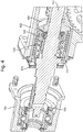
- Fig. 2 shows an embodiment of an apparatus to be used with a torque limiter 100, which may be similar to that shown in Fig. 1 , but where parts of the apparatus have been removed or modified to provide a faster and simpler manner in which to regulate the torque limiter by adjusting the force exerted by the resilient member thereof.
- the torque limiter 100 comprises a drive member or shaft 110 that is rotatable about an axis A, and similar to the embodiment of Fig. 1 the torque limiter 100 is contained at least partially within first and second housing portions 102 and 104 (see Fig. 4 ).
- the torque limiter 100 operates under the same principles as that of Fig. 1 , in that it functions to limit the torque applied between the drive shaft 110 and an output shaft 150.
- the shaft 110 comprises a portion 112 that connects to a coupling member 120 via a splined connection, such that the coupling member 120 can be slotted onto the shaft 110 and, once located on the shaft 110 will rotate with the shaft 110.
- the splined connection between the shaft 110 and the coupling member 120 may permit relative axial movement of the coupling member 120 along the shaft 110 (i.e., along the axis A).
- the torque limiter 100 further comprises a resilient member 130 (e.g., a spring) that is biased between the shaft 110 and the coupling member 120, so that the coupling member 120 is urged against the output shaft 150 by the resilient member 130. That is, the resilient member 130 urges the coupling member 120 in a direction away from the shoulder portion 114 of the shaft 110.
- the resilient member 130 is shown in isolation in Fig. 3B .
- shims or spacers are required (although some could be provided) between the radially extending surface 122 of the coupling member 120 and the resilient member 130 in order to regulate the force exerted by the resilient member 130.
- the torque limiter is adapted so that the force exerted by the resilient member 130 can be varied more easily and quickly.
- the shaft 110 comprises a screw thread 116 located on the opposite side of the shoulder portion 114 (in an axial direction) to the resilient member 130.
- the torque limiter 100 further comprises a nut 170 that is fastened onto and cooperates with this screw thread and may be rotated about the shaft 110 (and axis A) in order to move the nut 170 along the screw thread 116, such that the nut 170 moves in an axial direction.
- the nut 170 is also shown in isolation in Fig. 3A .
- the torque limiter 100 comprises an anti-rotation member 160 that is located concentrically around the shaft 110 and is fixed against rotation.
- the anti-rotation member 160 comprises a substantially annular portion 164 and a plurality of tines 162 that extend axially towards the shoulder portion 114 of the shaft 110.
- the nut 170 comprises a plurality of circumferentially spaced notches 172. These may be formed by cutting out a notch in the circumference of the nut 170.
- the notches 172 may each comprise a circumferential width W, and extend from one axial end of the nut 170 to the other, such that the width W of each notch 172 is maintained along the axial length of the nut 170.
- the notches 172 may instead be provided in the form of cavities that extend axially through the body of the nut 170 and have the same width W along its axial length.
- the tines 162 of the anti-rotation member 160 have a circumferential width W corresponding substantially to that of the notches 172, such that they are configured to slot into the notches 172 upon assembly of the torque limiter 100.
- W the circumferential width
- the nut 170 is also restricted from radial movement when the tines 162 of the anti-rotation member 160 engage with the notches 172 of the nut 170.
- the anti-rotation member 160 may be removed so that the tines 162 thereof disengage with the notches 172.
- the torque limiter 100 comprises a movable abutment 180 that is located concentrically around the shaft 110 and comprises an annular portion 184 comprising a radially and circumferentially extending face 185, as well as a number of tines 182 that extend from an opposite face 186 in an axial direction.
- the tines 182 may project from a radially outermost circumference of the face 186 of the annular portion 184 and in a direction away from the resilient member 130.
- the tines 182 are configured to contact the nut 170, for example a radially extending face 174 thereof, such that rotation of the nut 170 causes a corresponding axial movement of the movable abutment 180.
- the movable abutment 180 is shown in isolation in Fig. 3D
- the first and second housing portions 102, 104 are detachable from one another, in the same manner as the torque limiter 1 described in respect of Fig. 1 .
- the adjustment of the force exerted by the resilient member 130 may be carried out without disassembling the components inside the first housing portion 102.
- Various features described in connection with this embodiment allow such adjustment to be carried out precisely and more simply and quickly, as described in more detail below.
- the anti-rotation member 160 is pulled out, which may be done by detaching the first and second housing portions 102, 104 from one another as shown in Fig. 4 .
- the nut 170 may then be rotated to a suitable angle, which corresponds to a suitable axial position of the nut 170.
- the movable abutment 180 Upon rotation of the nut 170, the movable abutment 180 will move in an axial direction corresponding to the distance that the nut 170 moves in an axial direction as a result of its rotation. This movement of the movable abutment 180 will cause the resilient member 130 to compress or decompress (depending upon the direction of the axial movement) and change the force exerted by the resilient member 130 on the coupling member 120.
- the anti-rotation member 160 can be inserted back into position, such that the tines 162 of the anti-rotation member 160 pass through respective notches 172 of the nut 170.
- the circumferential position of the notches 172 can be configured to provide set amounts of axial movement.
- the notches 172 may be spaced equally about the circumference of the nut 170 so that that the nut 170 can only move a set amount in the axial direction.
- the set amount can be chosen for any particular application, but may be a value less than about 1 mm, 0.5 mm or even 0.1 mm.
- notches 172 each separated by an angle of about 36 degrees from an adjacent notch 172, wherein a rotation of 36 degrees of the nut 170 corresponds to an axial movement of the nut 170 (along the axis A) of 0.1 mm with an error of less than 1%.
- any number of notches 172 may be provided (e.g., more or less than 10), and the screw thread 116 could be tailored to provide any desired amount of axial movement.
- the shaft 110 and/or nut 170 may comprise visual and/or tactile features 117, 177 that indicate to a user the rotational position of the nut 170 with respect to the shaft 110.
- the features include identification marks 177 located circumferentially around a radially extending face 176 of the nut 170 that faces away from the shoulder portion 114 of the shaft 110 in use.
- the circumferential position of the marks 177 corresponds to the circumferential position of the notches 172, and further marks 179 may be provided to indicate the set amount of axial movement that is achieved upon rotation of the nut 170.
- Figs. 7A and 7B show one embodiment of a torque limiter 100 that may be used with the apparatus claimed and described in the present disclosure.
- the torque limiter 100 may be substantially the same as that described above in respect of Figs. 2-6 , that is comprising an input shaft 110 and an output shaft 150, wherein in use rotation of the input shaft 110 causes a corresponding rotation of the output shaft 150. Torque is transmitted from the input shaft 110 to the output shaft 150, which is provided in the form of a sleeve located concentrically around the input shaft 110.
- the output shaft 150 may comprise an intermediate portion 152 comprising a screw thread (not shown) configured to cooperate with a component (e.g., a flight control surface) for driving the component.
- a component e.g., a flight control surface
- the screw thread could form part of a worm screw.
- the input shaft 110 will transmit an input torque to the coupling member 120, such that the coupling member 120 rotates with the input shaft 110. This may be achieved using a splined arrangement as described above. Torque is then transferred from the coupling member 120 onto the output shaft 150 via an axial extension 122 of the coupling member 120.
- the axial extension 122 fits within a circumferential groove 154 of the output shaft 150 and presses against axially extending cam surfaces 156 thereof in order to transmit torque from the coupling member 120 to the output shaft 150 as aforesaid.
- the axially extending surfaces 156 are spaced apart in the circumferential direction and are angled so that abutting surfaces of the axial extension 122 of the coupling member 120 can ride up the surfaces 156 in use.
- the axial extension 122 of the coupling member 120 will ride up the cam surfaces 156 of the output shaft 150, and force the coupling member 120 axially away from the output shaft 150, ultimately disengaging the axial extension 122 from the circumferential cavity 154.
- the cam surface 156 of the coupling member 120 is completely disengaged from the circumferential cavity 154, the input shaft 110 is free to rotate relative to the output shaft 150, and an axially extending surface 111 of the input shaft 110 will rotate relative to an extension 111a of the outer resilient member 190.
- the torque limiter of various aspects and embodiments of the present disclosure is not limited to the particular type of torque limiter shown in the illustrated embodiments.
- the technology described herein may be applied to any torque limiter in which a force exerted by a resilient member adjusts a torque limit of the torque limiter.
Landscapes
- Engineering & Computer Science (AREA)
- General Engineering & Computer Science (AREA)
- Mechanical Engineering (AREA)
- Transmission Devices (AREA)
- One-Way And Automatic Clutches, And Combinations Of Different Clutches (AREA)
Priority Applications (4)
| Application Number | Priority Date | Filing Date | Title |
|---|---|---|---|
| EP19159100.7A EP3699448A1 (de) | 2019-02-25 | 2019-02-25 | Regelungsvorrichtung für drehmomentbegrenzer |
| CA3064881A CA3064881A1 (en) | 2019-02-25 | 2019-12-11 | Regulating device for torque limiter |
| US16/710,050 US20200271172A1 (en) | 2019-02-25 | 2019-12-11 | Regulating device for torque limiter |
| BR102019026586-8A BR102019026586A2 (pt) | 2019-02-25 | 2019-12-13 | Aparelho para regular um limitador de torque, e, limitador de torque |
Applications Claiming Priority (1)
| Application Number | Priority Date | Filing Date | Title |
|---|---|---|---|
| EP19159100.7A EP3699448A1 (de) | 2019-02-25 | 2019-02-25 | Regelungsvorrichtung für drehmomentbegrenzer |
Publications (1)
| Publication Number | Publication Date |
|---|---|
| EP3699448A1 true EP3699448A1 (de) | 2020-08-26 |
Family
ID=65576209
Family Applications (1)
| Application Number | Title | Priority Date | Filing Date |
|---|---|---|---|
| EP19159100.7A Withdrawn EP3699448A1 (de) | 2019-02-25 | 2019-02-25 | Regelungsvorrichtung für drehmomentbegrenzer |
Country Status (4)
| Country | Link |
|---|---|
| US (1) | US20200271172A1 (de) |
| EP (1) | EP3699448A1 (de) |
| BR (1) | BR102019026586A2 (de) |
| CA (1) | CA3064881A1 (de) |
Cited By (1)
| Publication number | Priority date | Publication date | Assignee | Title |
|---|---|---|---|---|
| EP4155568A1 (de) * | 2021-09-25 | 2023-03-29 | Hamilton Sundstrand Corporation | Anordnung eines drehmomentbegrenzers eines rollladens mit torsionsfeder |
Citations (4)
| Publication number | Priority date | Publication date | Assignee | Title |
|---|---|---|---|---|
| US2275004A (en) * | 1940-10-22 | 1942-03-03 | Fred H Behl | Shaft coupling |
| GB710246A (en) * | 1952-10-07 | 1954-06-09 | Geo Monro Ltd | Improvements in overload release devices for driving shafts |
| US3889490A (en) * | 1974-05-16 | 1975-06-17 | Felix J Nadolny | Torque control adaptor for ratchet wrench |
| US20070267266A1 (en) * | 2006-05-16 | 2007-11-22 | Man Lee-Liao | Transmission for transmitting torque smaller than adjustable value |
-
2019
- 2019-02-25 EP EP19159100.7A patent/EP3699448A1/de not_active Withdrawn
- 2019-12-11 CA CA3064881A patent/CA3064881A1/en not_active Abandoned
- 2019-12-11 US US16/710,050 patent/US20200271172A1/en not_active Abandoned
- 2019-12-13 BR BR102019026586-8A patent/BR102019026586A2/pt not_active IP Right Cessation
Patent Citations (4)
| Publication number | Priority date | Publication date | Assignee | Title |
|---|---|---|---|---|
| US2275004A (en) * | 1940-10-22 | 1942-03-03 | Fred H Behl | Shaft coupling |
| GB710246A (en) * | 1952-10-07 | 1954-06-09 | Geo Monro Ltd | Improvements in overload release devices for driving shafts |
| US3889490A (en) * | 1974-05-16 | 1975-06-17 | Felix J Nadolny | Torque control adaptor for ratchet wrench |
| US20070267266A1 (en) * | 2006-05-16 | 2007-11-22 | Man Lee-Liao | Transmission for transmitting torque smaller than adjustable value |
Cited By (2)
| Publication number | Priority date | Publication date | Assignee | Title |
|---|---|---|---|---|
| EP4155568A1 (de) * | 2021-09-25 | 2023-03-29 | Hamilton Sundstrand Corporation | Anordnung eines drehmomentbegrenzers eines rollladens mit torsionsfeder |
| US12169010B2 (en) | 2021-09-25 | 2024-12-17 | Hamilton Sundstrand Corporation | Assembly of torsional spring type roller jammer torque limiter |
Also Published As
| Publication number | Publication date |
|---|---|
| CA3064881A1 (en) | 2020-08-25 |
| BR102019026586A2 (pt) | 2020-09-29 |
| US20200271172A1 (en) | 2020-08-27 |
Similar Documents
| Publication | Publication Date | Title |
|---|---|---|
| US10180166B2 (en) | Disconnect mechanisms | |
| US6202803B1 (en) | Output load limiter | |
| US3091316A (en) | Overridable clutch mechanism | |
| US4402236A (en) | Regulating apparatus for a steering wheel | |
| CA2890718C (en) | Torque limiter | |
| US11118664B2 (en) | Limited slip differential with clutch for inhibiting speed differentiation between side gears | |
| US11390372B2 (en) | Force application device for an aircraft control stick | |
| US4468206A (en) | Torque-limiting clutch | |
| EP3222868B1 (de) | Kupplung mit kerbverzahnung | |
| US5092441A (en) | Manually restorable overload clutch | |
| US7036644B2 (en) | Torque-transmitting mechanism with latching apparatus | |
| US3111822A (en) | Controlled torque, self-energizing wrap spring clutch or brake | |
| EP3699448A1 (de) | Regelungsvorrichtung für drehmomentbegrenzer | |
| US4932809A (en) | Lost motion splined coupling device | |
| US5769362A (en) | Aircraft control mechanism for a speed brake | |
| US2510667A (en) | Overload torque release device | |
| EP2927539A1 (de) | Betätigungsvorrichtung für eine Kupplung | |
| US3425526A (en) | Coil clutch with coil pilot brake | |
| EP3224137B1 (de) | Kupplungsvorrichtung | |
| EP3447325B1 (de) | Indikatorsystem für drehmomentbegrenzer | |
| GB2122282A (en) | Overload release coupling | |
| EP3318775B1 (de) | Vorrichtung für drehmomentbegrenzende einrichtung | |
| US10663009B2 (en) | Self-contained switchable wedge clutch | |
| GB1597631A (en) | Slack adjuster mechanism | |
| EP3751165B1 (de) | Überlastkupplung mit zweiter stufeneinstellung |
Legal Events
| Date | Code | Title | Description |
|---|---|---|---|
| PUAI | Public reference made under article 153(3) epc to a published international application that has entered the european phase |
Free format text: ORIGINAL CODE: 0009012 |
|
| STAA | Information on the status of an ep patent application or granted ep patent |
Free format text: STATUS: THE APPLICATION HAS BEEN PUBLISHED |
|
| AK | Designated contracting states |
Kind code of ref document: A1 Designated state(s): AL AT BE BG CH CY CZ DE DK EE ES FI FR GB GR HR HU IE IS IT LI LT LU LV MC MK MT NL NO PL PT RO RS SE SI SK SM TR |
|
| AX | Request for extension of the european patent |
Extension state: BA ME |
|
| STAA | Information on the status of an ep patent application or granted ep patent |
Free format text: STATUS: THE APPLICATION IS DEEMED TO BE WITHDRAWN |
|
| 18D | Application deemed to be withdrawn |
Effective date: 20210227 |