EP3699500A1 - Modulierte heizungs-/kühlsystemsteuerung - Google Patents
Modulierte heizungs-/kühlsystemsteuerung Download PDFInfo
- Publication number
- EP3699500A1 EP3699500A1 EP20157631.1A EP20157631A EP3699500A1 EP 3699500 A1 EP3699500 A1 EP 3699500A1 EP 20157631 A EP20157631 A EP 20157631A EP 3699500 A1 EP3699500 A1 EP 3699500A1
- Authority
- EP
- European Patent Office
- Prior art keywords
- inlet
- outlet
- temperature
- mixing valve
- ratio
- Prior art date
- Legal status (The legal status is an assumption and is not a legal conclusion. Google has not performed a legal analysis and makes no representation as to the accuracy of the status listed.)
- Granted
Links
Images






Classifications
-
- F—MECHANICAL ENGINEERING; LIGHTING; HEATING; WEAPONS; BLASTING
- F24—HEATING; RANGES; VENTILATING
- F24D—DOMESTIC- OR SPACE-HEATING SYSTEMS, e.g. CENTRAL HEATING SYSTEMS; DOMESTIC HOT-WATER SUPPLY SYSTEMS; ELEMENTS OR COMPONENTS THEREFOR
- F24D19/00—Details
- F24D19/10—Arrangement or mounting of control or safety devices
- F24D19/1006—Arrangement or mounting of control or safety devices for water heating systems
- F24D19/1009—Arrangement or mounting of control or safety devices for water heating systems for central heating
- F24D19/1015—Arrangement or mounting of control or safety devices for water heating systems for central heating using a valve or valves
- F24D19/1018—Radiator valves
-
- F—MECHANICAL ENGINEERING; LIGHTING; HEATING; WEAPONS; BLASTING
- F24—HEATING; RANGES; VENTILATING
- F24H—FLUID HEATERS, e.g. WATER OR AIR HEATERS, HAVING HEAT-GENERATING MEANS, e.g. HEAT PUMPS, IN GENERAL
- F24H15/00—Control of fluid heaters
- F24H15/30—Control of fluid heaters characterised by control outputs; characterised by the components to be controlled
- F24H15/305—Control of valves
- F24H15/315—Control of valves of mixing valves
-
- F—MECHANICAL ENGINEERING; LIGHTING; HEATING; WEAPONS; BLASTING
- F24—HEATING; RANGES; VENTILATING
- F24D—DOMESTIC- OR SPACE-HEATING SYSTEMS, e.g. CENTRAL HEATING SYSTEMS; DOMESTIC HOT-WATER SUPPLY SYSTEMS; ELEMENTS OR COMPONENTS THEREFOR
- F24D19/00—Details
- F24D19/10—Arrangement or mounting of control or safety devices
- F24D19/1006—Arrangement or mounting of control or safety devices for water heating systems
- F24D19/1009—Arrangement or mounting of control or safety devices for water heating systems for central heating
- F24D19/1015—Arrangement or mounting of control or safety devices for water heating systems for central heating using a valve or valves
-
- F—MECHANICAL ENGINEERING; LIGHTING; HEATING; WEAPONS; BLASTING
- F24—HEATING; RANGES; VENTILATING
- F24D—DOMESTIC- OR SPACE-HEATING SYSTEMS, e.g. CENTRAL HEATING SYSTEMS; DOMESTIC HOT-WATER SUPPLY SYSTEMS; ELEMENTS OR COMPONENTS THEREFOR
- F24D19/00—Details
- F24D19/10—Arrangement or mounting of control or safety devices
- F24D19/1006—Arrangement or mounting of control or safety devices for water heating systems
- F24D19/1009—Arrangement or mounting of control or safety devices for water heating systems for central heating
- F24D19/1015—Arrangement or mounting of control or safety devices for water heating systems for central heating using a valve or valves
- F24D19/1024—Arrangement or mounting of control or safety devices for water heating systems for central heating using a valve or valves a multiple way valve
-
- F—MECHANICAL ENGINEERING; LIGHTING; HEATING; WEAPONS; BLASTING
- F24—HEATING; RANGES; VENTILATING
- F24D—DOMESTIC- OR SPACE-HEATING SYSTEMS, e.g. CENTRAL HEATING SYSTEMS; DOMESTIC HOT-WATER SUPPLY SYSTEMS; ELEMENTS OR COMPONENTS THEREFOR
- F24D19/00—Details
- F24D19/10—Arrangement or mounting of control or safety devices
- F24D19/1006—Arrangement or mounting of control or safety devices for water heating systems
- F24D19/1009—Arrangement or mounting of control or safety devices for water heating systems for central heating
- F24D19/1015—Arrangement or mounting of control or safety devices for water heating systems for central heating using a valve or valves
- F24D19/1024—Arrangement or mounting of control or safety devices for water heating systems for central heating using a valve or valves a multiple way valve
- F24D19/1033—Arrangement or mounting of control or safety devices for water heating systems for central heating using a valve or valves a multiple way valve motor operated
-
- F—MECHANICAL ENGINEERING; LIGHTING; HEATING; WEAPONS; BLASTING
- F24—HEATING; RANGES; VENTILATING
- F24F—AIR-CONDITIONING; AIR-HUMIDIFICATION; VENTILATION; USE OF AIR CURRENTS FOR SCREENING
- F24F11/00—Control or safety arrangements
- F24F11/70—Control systems characterised by their outputs; Constructional details thereof
- F24F11/80—Control systems characterised by their outputs; Constructional details thereof for controlling the temperature of the supplied air
- F24F11/83—Control systems characterised by their outputs; Constructional details thereof for controlling the temperature of the supplied air by controlling the supply of heat-exchange fluids to heat-exchangers
- F24F11/84—Control systems characterised by their outputs; Constructional details thereof for controlling the temperature of the supplied air by controlling the supply of heat-exchange fluids to heat-exchangers using valves
-
- F—MECHANICAL ENGINEERING; LIGHTING; HEATING; WEAPONS; BLASTING
- F24—HEATING; RANGES; VENTILATING
- F24F—AIR-CONDITIONING; AIR-HUMIDIFICATION; VENTILATION; USE OF AIR CURRENTS FOR SCREENING
- F24F11/00—Control or safety arrangements
- F24F11/88—Electrical aspects, e.g. circuits
-
- G—PHYSICS
- G06—COMPUTING OR CALCULATING; COUNTING
- G06F—ELECTRIC DIGITAL DATA PROCESSING
- G06F1/00—Details not covered by groups G06F3/00 - G06F13/00 and G06F21/00
- G06F1/16—Constructional details or arrangements
- G06F1/20—Cooling means
- G06F1/206—Cooling means comprising thermal management
-
- G—PHYSICS
- G06—COMPUTING OR CALCULATING; COUNTING
- G06F—ELECTRIC DIGITAL DATA PROCESSING
- G06F2200/00—Indexing scheme relating to G06F1/04 - G06F1/32
- G06F2200/20—Indexing scheme relating to G06F1/20
- G06F2200/201—Cooling arrangements using cooling fluid
Definitions
- aspects of the disclosure relate to thermally modulating individual radiators, underfloor heating circuits, chilled beams or fan-coils of a heating/cooling system.
- Heating/cooling systems with hydronic emitters are based on power transfer from one or more of the hydronic emitters to affect one or more environmental entities (for example, offices, apartments, conference rooms, and the like).
- Traditional approaches often modulate the flow temperature directly from the boiler, where only a single available modulated output is available.
- Traditional approaches may support two separate heating outputs, but costs increase dramatically with dual outputs. Consequently, with traditional approaches multiple heating zones for a building may be economically impracticable.
- a special modulating heat source for example, a boiler
- a boiler may be required.
- An aspect supports a hydronic heating/cooling system having a mixing valve that mixes water flows from a water flow pipe and a water return pipe.
- the mixed water flows through an outlet of the mixing valve to a hydronic emitter that either heats or cools a controlled entity such as a room, office, or conference room.
- a hydronic heating/cooling systems controls multiple heating/cooling zones, where each zone spans separate controlled entities and has a corresponding mixing valve and hydronic emitter.
- a targeted temperature of an outlet of a mixing value is determined from temperature information from a thermostat.
- a water flow ratio of two inlets of the mixing value may then be obtained from the targeted temperature.
- the mixing valve may then be configured through an actuator based on a water flow ratio. The water flow ratio may be adjusted so that a measured temperature of an outlet of a mixing value approximately equals the targeted temperature.
- an actuator includes a motor, an electrical signal is applied to the motor, and the electrical signal characterized by an electrical voltage value.
- the electrical voltage causes the motor to adjust a mixing valve to pass the water flows through the first A inlet and the first B inlet in accordance with an inlet ratio.
- the electrical voltage value may be based on a targeted outlet temperature at the outlet of the mixing valve.
- a controller waits a predetermined time duration for the system to thermally stabilize before obtaining updated first temperature information. The controller then generates an updated targeted temperature for the outlet of the mixing valve.
- heating systems typically use typically "on/off' thermostatic controls. These traditional approaches involve monitoring the room temperature with a thermostatic control and turning the heating on or off to maintain the room temperature as close as possible to the room setpoint temperature.
- Modulating thermostatic controls may modulate the water flow temperature such that as the room temperature approaches the room setpoint temperature, the water flow temperature is reduced. The result is that modulation control may be advantageous over simple "on/off' control because room temperature variation may be decreased by temperature over-shoot or temperature under-shoot and may be more energy efficient.
- modulation controls consist of two parts: 1) a modulating thermostatic control that monitors the room temperature and the room setpoint and 2) a modulating appliance (boiler) that modulates the water flow temperature.
- a standardized communication protocol is used such that the thermostatic control requests the boiler to provide the required flow water temperature to control the room temperature to achieve the room setpoint.
- Different modulating appliances and controls may use different protocols.
- different thermostatic controls may be needed for different modulating appliances. There are disadvantages with traditional modulating controls.
- modulating the flow temperature directly from the boiler may provide only a single available modulated output is available.
- Traditional approaches may support two separate heating outputs, but costs increase dramatically with dual outputs. Consequently, with traditional approaches multiple heating zones for a building may be economically impracticable.
- a special modulating heat source for example, a boiler
- a boiler for example, a boiler
- Achieving a low flow temperature as may be required during times when the outside weather conditions are mild (such as during the spring and autumn), normally cannot be achieved with flow temperature directly from the boiler.
- This results in the modulating thermostatic control having to revert to "on/off' control rather than using modulating control when a low-load situation is encountered due to the modulating boiler being incapable of modulating down to low flow temperatures.
- modulation control may utilize one or more three or four port mixing valve(s) together with an electronic control to provide an enhanced modulation control to the heating/cooling emitters.
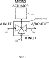
- FIG. 1 shows mixing valve 101 in accordance with an embodiment.
- Mixing valve 101 includes A inlet 102, B inlet 103, and A/B outlet 104.
- water flows through inlets 102 and 103 are controlled by actuator 105, resulting in a mixed water flow through outlet 104.
- Figure 1 shows a three-port mixer
- some embodiments may utilize a four-port mixer, where a B inlet has two connections. Operation may be similar as with a three-port mixer.
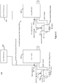
- FIG. 2 shows hydronic heating system 200 in accordance with an embodiment.
- a inlet 102 is fed from heat generator (boiler) 201 with heated water typically between 70°C and 90°C (shown at 75°C in Figure 2 ) through flow pipe 203.
- B Inlet 103 is fed from return pipe 204 of the hydronic emitters (for example, radiators in a radiator-based heating system).
- Water flow through return pipe 204 typically has a lower temperature (typically 10°C lower than through flow pipe 203) due to heat being extracted from the radiator from the radiator water flow.
- A/B outlet 104 water flow is fed to hydronic emitters (for example, radiators).
- Mixing valve 101 mixes water flow from heat generator 201 through A inlet 102 and water flow from return pipe 204 through B inlet 103 to obtain a mixed water flow through A/B outlet 104.
- the proportion may be varied, for example, to allow 100% from A and 0% from B, 0% from A and 100% from B, or any ratio in-between.
- An actuator (shown as actuator 105 in Figure 1 ) is connected to mixing valve 101 to control and alter the A/B flow ratio to obtain the required (targeted) flow temperature at A/B outlet 104 as will be discussed in further detail.
- heating system 200 determines a targeted outlet temperature at A/B outlet 104 and measures the actual outlet temperature through temperature sensor 202.
- FIG. 3 shows hydronic emitter 301 within a hydronic heating/cooling system 300.
- heated water flows through hydronic emitter 301 (including radiators, underfloor heating/cooling circuits, fan coils, chilled beams) via water flow pipe 303, mixing valve 302, and A/B outlet 307 and exits emitter 301 via return 103 and water return pipe 304.
- Mixing valve 302 provides a mixed water flow to emitter 301 by appropriately mixing water flows from A inlet 305 and B inlet 306 so that a measured temperature measured by temperature sensor 308 approximately equals a targeted temperature as will be discussed in further detail.
- hydronic system 300 While hydronic system 300 operates in a heating mode, hydronic system may also support a cooling mode.
- an environmental conditioner for example, a heat exchanger
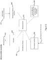
- FIG. 4 shows a controller component of a hydronic heating/cooling system in accordance with an embodiment.
- the controller component comprises modulation-thermostatic controller 401 and actuator controller 402.
- actuator 105 configures mixing valve 101 (also shown in Figure 1 ) and actuator to obtain a desired flow temperature to a hydronic emitter (not explicitly shown).
- Modulation-thermostatic controller 401 receives temperature information (for example, a measured room temperature 451 and temperature setpoint 452) from a thermostat situated in a thermally-controlled entity (for example, an office, apartment, conference room, and the like). Modulation-thermostatic controller 401 then determines targeted outlet temperature 453 of the associated A/B outlet (not explicitly shown). The determination may be performed through different ways, including a lookup table or predetermined relationship between the temperature information 451 and 452 and targeted outlet temperature 453.
- Actuator controller 402 receives targeted outlet temperature 453 from modulation-thermostatic controller 401. Actuator controller 402 then determines inlet ratio 454 that corresponds to the targeted outlet temperature 453 and measured outlet temperature 455 (for example, provided by temperature sensor 308 shown in Figure 3 ). Inlet ratio 454 is indicative of a water flow ratio of the A inlet 102 to the first B inlet 103 needed to obtain a first desired mixed water flow through A/B outlet 104 of mixing valve 101.
- the voltage of an electrical signal to actuator 105 from actuator controller 402 may be indicative or inlet ratio 454.
- Control of mixing valve 101 may be performed by actuator 105 such as an open/close motorized actuator or a 0-10v control actuator.
- An open/close motorized actuator control may be supported by moving actuator 105 in the open or close direction by applying a fixed voltage normally 24 VAC or 240 VAC. If actuator 105 is opened more, water flow through A inlet 102 increases and water flow through B inlet 103 decreases. If actuator 105 is closed more, water flow though A inlet 102 decreases and water flow through B inlet 103 increases.
- actuator 105 With 0-10 VDC control, greater precision is possible with actuator 105.
- 0v When 0v is applied to the actuator 105, water flow though A inlet 102 is 0% and water flow through B inlet 103 is 100%.
- 2.5v When 2.5v is applied to actuator 105, water flow through A inlet 102 is 25% and water flow through B inlet 103 is 75%.
- 5v When 5v is applied to actuator 105, water flows through A inlet 102 and B inlet 103 are both at 50%.
- 10v When 10v is applied to actuator 105, water flow through A inlet 102 is 100% and water flow through B inlet 103 is 0%.
- temperature sensor 308 may be placed on the A/B outlet 104 such that actuator 105 can control A/B outlet 104 to be at targeted (desired) temperature.
- temperature sensor 308 may be placed on the A/B outlet 104 such that actuator 105 can control A/B outlet 104 to be at targeted (desired) temperature.
- mixing valve 101 needs to allow more water flow through A inlet 102 and less water flow through B inlet 103.
- A/B outlet 104 is above the targeted temperature, then mixing valve 101 needs to allow less water flow through A inlet 102 and more water flow through B inlet 103.
- FIG. 5 shows controller assembly 500 of a hydronic heating/cooling system in accordance with an embodiment.
- Controller assembly 500 may provide the controlling capabilities of the controller component shown in Figure 4 .
- Controller assembly 500 obtains thermostat signal 551, which may be indicative of the temperature set point and current room temperature via thermostat interface 502. Controller assembly 500 may receive signal 551 through various communication media, including wireless or wired channels using different communication protocols.
- Processor 501 processes signal 551 in accordance with computer readable instructions obtained from memory device 503.
- the computer readable instructions may reflect flowchart 900 and/or flowchart 1000 shown in Figures 9 and 10 , respectively, as will be discussed.
- processor 501 controls water flow though hydronic emitter 301 (as shown in Figure 3 ) by configuring valve mixer 101 through actuator 105.
- Processor 501 also obtains measured temperatures measured at A/B outlet 104 (as shown in Figure 1 ) via temperature sensor interface 505 from temperature sensor 202.
- processor 501 obtains the room temperature and temperature setpoint extracted from signal 551 and consequently determines a targeted temperature for A/B outlet 104. For example, processor 501 may perform this determination from a lookup table stored at memory device 504.
- the computing system environment may include a computing device wherein the processes discussed herein may be implemented.
- the computing device may have a processor 501 for controlling overall operation of the computing device and its associated components, including RAM, ROM, communications module, and memory devices 503 and 504.
- the computing device typically includes a variety of computer readable media.
- Computer readable media may be any available media that may be accessed by computing device and include both volatile and nonvolatile media, removable and non-removable media.
- computer readable media may comprise a combination of computer storage media and communication media.
- Computer storage media may include volatile and nonvolatile, removable and non-removable media implemented in any method or technology for storage of information such as computer readable instructions, data structures, program modules or other data.
- Computer storage media include, but is not limited to, random access memory (RAM), read only memory (ROM), electronically erasable programmable read only memory (EEPROM), flash memory or other memory technology, CD-ROM, digital versatile disks (DVD) or other optical disk storage, magnetic cassettes, magnetic tape, magnetic disk storage or other magnetic storage devices, or any other medium that can be used to store the desired information and that can be accessed by the computing device.
- Communication media typically embodies computer readable instructions, data structures, program modules or other data in a modulated data signal such as a carrier wave or other transport mechanism and includes any information delivery media.
- Modulated data signal is a signal that has one or more of its characteristics set or changed in such a manner as to encode information in the signal.
- communication media includes wired media such as a wired network or direct-wired connection, and wireless media such as acoustic, RF, infrared and other wireless media.
- memory devices 503 and 504 may be physically implemented within a single memory device.
- Controller assembly 500 may be implemented in a centralized or a distributed manner. When centralized, assembly 500 may be located at a single position to control one or more heating/cooling zones. When distributed, assembly 500 may dispersed over a plurality of positions. For example, as shown in Figure 6 , separate controllers for each heating/cooling zone may be located near each of the corresponding hydronic emitter.
- Figure 6 shows a heating/cooling system 600 with two heating/cooling zones in accordance with an embodiment.
- an environmental conditioner for example, a boiler
- a single water temperature applicable to the entire building structure.
- embodiments water flow is controlled separately for different hydronic emitters associated with different portions (for example, rooms) of the building structure (for example, a house) rather than at the boiler itself. Consequently, embodiments may support multiple heating/cooling zones.
- Using a mixing valve to provide a modulated flow temperature may have several advantages to a traditional approach of using a modulating boiler directly to provide the flow temperature. For example, when upgrading to modulation control, the existing non-modulating boiler may be used. Modulation may be used with any type of heat generator such as electric boiler, solid fuel boiler, oil fired boiler or District Heating (DH) systems. Multiple mixing valves may be used to provide multi-zone modulation control from one single heat generator. In addition, low temperature output is possible to provide modulation even at low-load conditions.
- DH District Heating
- first zone and second zones are configured through thermostats 603 and 604, respectively and where first and second zones are heated/cooled by hydronic emitters 601 and 602, respectively.
- Thermostats 603 and 604 provide first and second temperature information 651 and 652, respectively, which may include room temperature and temperature setpoints for each zone.
- Control signals 653 and 654 may convey control information via voltage characteristics of the signal.
- FIG 7A shows relationship 701 between targeted temperature 703 of an outlet of a mixing valve and temperature difference 702 when a heating/cooling system is operating in a heating mode.
- Temperature difference 702 may be derived from temperature information (for example, information 451 and 452 as shown in Figure 4 ) provided by a thermostat by subtracting a measured temperature of the controlled entity (for example, a room temperature) from a temperature setpoint.
- targeted temperature 703 varies between the temperature of flow pipe 303 and return pipe 304 (in other words, between T flow and T return ).
- T flow and T return may be known a priori or may be measured by temperature sensors at flow pipe 303 and return pipe 304, respectively.
- FIG 7B shows relationship 704 between targeted temperature 706 of an outlet of a mixing valve and temperature difference 705 when a heating/cooling system is operating in a cooling mode.
- Temperature difference 705 may be obtained from temperature information (for example, information 451 and 452 as shown in Figure 4 ) from a thermostat by subtracting a temperature setpoint from a measured temperature of the controlled entity (for example, the room temperature).
- T flow and T return may be known a priori or may be measured by temperature sensors at flow pipe 303 and return pipe 304.
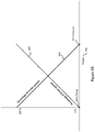
- Figure 8A shows relative water flows though inlets of a valve mixer when a heating/cooling system is operating in a heating mode.
- Percentage 801 (corresponding to a A inlet of a mixing valve) and percentage 802 (corresponding to a B inlet) are based on targeted temperature 703 obtained from the relationship shown in Figure 7A (operating in a heating mode), where percentage 801 to percentage 802 equals an inlet ratio and where percentage 801 plus percentage 802 equals 100%.
- Figure 8B shows relative water flows though inlets of a valve mixer when a heating/cooling system is operating in a cooling mode.
- Percentage 804 (corresponding to a A inlet of a mixing valve) and percentage 805 (corresponding to a B inlet) are based on targeted temperature 706 obtained from the relationship shown in Figure 7B , where percentage 804 to percentage 805 equals an inlet ratio and where percentage 804 plus percentage 805 equals 100%.
- Figure 9 shows flowchart 900 for a heating/cooling system when operating in a heating mode in accordance with an embodiment.
- controller assembly 500 obtains temperature information from a thermostat via thermostat interface 502.
- the temperature information may include a measured room temperature and a temperature setpoint. Based on the temperature information, a targeted temperature of the A/B outlet of the corresponding mixing valve is determined at block 902.
- controller assembly 500 adjusts the openings of A inlet and B inlet of the mixing valve to obtain the targeted temperature of the A/B outlet. For example, with an open/close motorized actuator control, actuator 105 may be instructed to open or close inlet openings in an incremental manner based on a determined inlet ratio, thus resulting with the targeted temperature at the A/B outlet. However, as previously discussed, some embodiments may utilize an actuator with 0-10 volt control, where the voltage value directly maps to the inlet ratio. Consequently, execution of blocks 903, 904, 906, and 907 may be accelerated by applying a determined voltage value to actuator 105.
- Blocks 903, 940, 906, and 907 are executed until the measured temperature at the A/B outlet is within a temperature range of the targeted temperature ⁇ , where ⁇ is a predetermined offset.
- controller assembly 500 waits a predetermined time duration for the heating/cooling system to thermally stabilize and obtains updated temperature information at block 901. Process 900 is then repeated with the updated temperature information.
- FIG. 10 shows flowchart 1000 for a heating/cooling system when operating in a cooling mode in accordance with an embodiment.
- Flowchart 1000 is similar to flowchart 900, where blocks 1001-1007 correspond to blocks 901-907, respectively. However, blocks 1003 and 1004 are appropriately modified to operate in the cooling mode.
- the computer system may include at least one computer such as a microprocessor, digital signal processor, and associated peripheral electronic circuitry.
Landscapes
- Engineering & Computer Science (AREA)
- General Engineering & Computer Science (AREA)
- Chemical & Material Sciences (AREA)
- Combustion & Propulsion (AREA)
- Mechanical Engineering (AREA)
- Physics & Mathematics (AREA)
- Thermal Sciences (AREA)
- Theoretical Computer Science (AREA)
- Human Computer Interaction (AREA)
- General Physics & Mathematics (AREA)
- Steam Or Hot-Water Central Heating Systems (AREA)
- Control Of Temperature (AREA)
- Air Conditioning Control Device (AREA)
Applications Claiming Priority (1)
| Application Number | Priority Date | Filing Date | Title |
|---|---|---|---|
| US16/280,237 US10649508B1 (en) | 2019-02-20 | 2019-02-20 | Modulated heating/cooling system control |
Publications (2)
| Publication Number | Publication Date |
|---|---|
| EP3699500A1 true EP3699500A1 (de) | 2020-08-26 |
| EP3699500B1 EP3699500B1 (de) | 2024-04-03 |
Family
ID=69631429
Family Applications (1)
| Application Number | Title | Priority Date | Filing Date |
|---|---|---|---|
| EP20157631.1A Active EP3699500B1 (de) | 2019-02-20 | 2020-02-17 | Modulierte heizungs-/kühlsystemsteuerung |
Country Status (3)
| Country | Link |
|---|---|
| US (1) | US10649508B1 (de) |
| EP (1) | EP3699500B1 (de) |
| CN (2) | CN111678194A (de) |
Families Citing this family (4)
| Publication number | Priority date | Publication date | Assignee | Title |
|---|---|---|---|---|
| EP3966506B1 (de) * | 2019-05-05 | 2025-07-09 | FT Energy Controls, LLC | System und vorrichtung zur klimatisierung von innenraumluft |
| GB2602459B (en) | 2020-12-23 | 2022-12-28 | Idzv Ltd | A hydraulic unit |
| CN114388927B (zh) * | 2021-09-27 | 2024-04-16 | 岚图汽车科技有限公司 | 一种动力电池冷却控制方法及相关设备 |
| US12467653B2 (en) | 2023-02-02 | 2025-11-11 | Ft Energy Controls, Llc | System and method for controlling indoor environments |
Citations (4)
| Publication number | Priority date | Publication date | Assignee | Title |
|---|---|---|---|---|
| GB2127529A (en) * | 1982-09-24 | 1984-04-11 | Danfoss As | Hot water heating installation |
| DE3446167A1 (de) * | 1984-11-22 | 1986-05-22 | LGZ Landis & Gyr Zug AG, Zug | Regelgeraet fuer eine heizungsanlage |
| US5556027A (en) * | 1994-04-05 | 1996-09-17 | Fiedrich; Joachim | Hydronic heating outdoor temperature reset supply water temperature control system |
| AT401694B (de) * | 1994-03-24 | 1996-11-25 | Windhager Zentralheizung Gmbh | Regeleinrichtung für warmwasser-zentralheizungsanlagen |
Family Cites Families (7)
| Publication number | Priority date | Publication date | Assignee | Title |
|---|---|---|---|---|
| FR2740863B3 (fr) * | 1995-11-08 | 1998-02-20 | Axterm | Dispositif d'alimentation a partir d'une meme chaudiere de deux circuits d'eau chaude a des temperatures differentes |
| US7730935B1 (en) * | 1999-12-27 | 2010-06-08 | Carrier Corporation | Hydronic system control for heating and cooling |
| KR100952985B1 (ko) * | 2007-12-04 | 2010-04-15 | 주식회사 경동네트웍 | 난방시스템 제어방법 |
| CN102777959B (zh) * | 2012-08-24 | 2014-11-26 | 江苏联宏自动化系统工程有限公司 | 一种基于混水装置的供热调节和控制方法 |
| US20170219219A1 (en) * | 2016-02-01 | 2017-08-03 | Keith A. Miller | Demand based hvac (heating, ventilation, air conditioning) control |
| US10599167B2 (en) * | 2016-08-04 | 2020-03-24 | Watershed Technologies Inc. | System and method for building climate control |
| CN108954626A (zh) * | 2018-09-25 | 2018-12-07 | 深圳中科蓝天科技有限公司 | 一种楼宇供冷供暖系统及其控制方法 |
-
2019
- 2019-02-20 US US16/280,237 patent/US10649508B1/en active Active
-
2020
- 2020-02-13 CN CN202010091675.7A patent/CN111678194A/zh active Pending
- 2020-02-13 CN CN202410861560.XA patent/CN118669993A/zh active Pending
- 2020-02-17 EP EP20157631.1A patent/EP3699500B1/de active Active
Patent Citations (4)
| Publication number | Priority date | Publication date | Assignee | Title |
|---|---|---|---|---|
| GB2127529A (en) * | 1982-09-24 | 1984-04-11 | Danfoss As | Hot water heating installation |
| DE3446167A1 (de) * | 1984-11-22 | 1986-05-22 | LGZ Landis & Gyr Zug AG, Zug | Regelgeraet fuer eine heizungsanlage |
| AT401694B (de) * | 1994-03-24 | 1996-11-25 | Windhager Zentralheizung Gmbh | Regeleinrichtung für warmwasser-zentralheizungsanlagen |
| US5556027A (en) * | 1994-04-05 | 1996-09-17 | Fiedrich; Joachim | Hydronic heating outdoor temperature reset supply water temperature control system |
Also Published As
| Publication number | Publication date |
|---|---|
| CN111678194A (zh) | 2020-09-18 |
| CN118669993A (zh) | 2024-09-20 |
| EP3699500B1 (de) | 2024-04-03 |
| US10649508B1 (en) | 2020-05-12 |
Similar Documents
| Publication | Publication Date | Title |
|---|---|---|
| EP3699500B1 (de) | Modulierte heizungs-/kühlsystemsteuerung | |
| EP3561399B1 (de) | Temperatur-delta-regelung für ein hydraulisches heiz-/kühlsystem | |
| US20170219219A1 (en) | Demand based hvac (heating, ventilation, air conditioning) control | |
| US11649982B2 (en) | Systems and methods for using a smart valve to control conditioned air | |
| US8051903B2 (en) | Cooling and/or heating device | |
| CN109564438B (zh) | 区域制热中的返回温度的降低以及区域制冷中的返回温度的增加 | |
| DK2354682T3 (en) | Method and device for setting a temperature control device | |
| RU2671139C1 (ru) | Система управления температурой в помещении | |
| CA2360251C (en) | Method for controlling a heating system and heating system | |
| RU2676579C1 (ru) | Отопительная система | |
| EP3115703A1 (de) | Steuerung von heizung, lüftung, klimatisierung | |
| CN113825954A (zh) | 用于调节室内空气的系统和设备 | |
| US10914480B2 (en) | Building control system with decoupler for independent control of interacting feedback loops | |
| CN118896370A (zh) | 自适应阀控制系统 | |
| US20200393144A1 (en) | Efficient multi-zone multi-velocity hvac control method and apparatus | |
| US11149964B2 (en) | Flow control module and method for controlling the flow in a hydronic system | |
| HK40031848A (en) | Modulated heating/cooling system control | |
| US20250354698A1 (en) | Improvements to heating systems | |
| EP3587932B1 (de) | Impulsmodulierte steuerung für heizung, lüftung und klimatisierung | |
| EP3339753B1 (de) | System und verfahren zur durchsetzung eines manuell eingestellten temperatursollwerts in einem intelligenten wärmeverwaltungssystem | |
| CN110908413B (zh) | 温控器、主控器、温度调节系统及其控制方法 | |
| HK40013758B (en) | Temperature delta control for a hydronic heating/cooling system | |
| HK40013758A (en) | Temperature delta control for a hydronic heating/cooling system | |
| EP4498012A1 (de) | Hlk-system, verfahren zur aufrüstung eines bestehenden hlk-systems und kit zur aufrüstung eines bestehenden hlk-systems | |
| GB2619355A (en) | Improvements to heating systems |
Legal Events
| Date | Code | Title | Description |
|---|---|---|---|
| PUAI | Public reference made under article 153(3) epc to a published international application that has entered the european phase |
Free format text: ORIGINAL CODE: 0009012 |
|
| STAA | Information on the status of an ep patent application or granted ep patent |
Free format text: STATUS: THE APPLICATION HAS BEEN PUBLISHED |
|
| AK | Designated contracting states |
Kind code of ref document: A1 Designated state(s): AL AT BE BG CH CY CZ DE DK EE ES FI FR GB GR HR HU IE IS IT LI LT LU LV MC MK MT NL NO PL PT RO RS SE SI SK SM TR |
|
| AX | Request for extension of the european patent |
Extension state: BA ME |
|
| STAA | Information on the status of an ep patent application or granted ep patent |
Free format text: STATUS: REQUEST FOR EXAMINATION WAS MADE |
|
| 17P | Request for examination filed |
Effective date: 20210226 |
|
| RBV | Designated contracting states (corrected) |
Designated state(s): AL AT BE BG CH CY CZ DE DK EE ES FI FR GB GR HR HU IE IS IT LI LT LU LV MC MK MT NL NO PL PT RO RS SE SI SK SM TR |
|
| RAP3 | Party data changed (applicant data changed or rights of an application transferred) |
Owner name: COMPUTIME LTD. |
|
| STAA | Information on the status of an ep patent application or granted ep patent |
Free format text: STATUS: EXAMINATION IS IN PROGRESS |
|
| 17Q | First examination report despatched |
Effective date: 20220829 |
|
| GRAP | Despatch of communication of intention to grant a patent |
Free format text: ORIGINAL CODE: EPIDOSNIGR1 |
|
| STAA | Information on the status of an ep patent application or granted ep patent |
Free format text: STATUS: GRANT OF PATENT IS INTENDED |
|
| INTG | Intention to grant announced |
Effective date: 20240105 |
|
| GRAS | Grant fee paid |
Free format text: ORIGINAL CODE: EPIDOSNIGR3 |
|
| GRAA | (expected) grant |
Free format text: ORIGINAL CODE: 0009210 |
|
| STAA | Information on the status of an ep patent application or granted ep patent |
Free format text: STATUS: THE PATENT HAS BEEN GRANTED |
|
| AK | Designated contracting states |
Kind code of ref document: B1 Designated state(s): AL AT BE BG CH CY CZ DE DK EE ES FI FR GB GR HR HU IE IS IT LI LT LU LV MC MK MT NL NO PL PT RO RS SE SI SK SM TR |
|
| REG | Reference to a national code |
Ref country code: CH Ref legal event code: EP |
|
| REG | Reference to a national code |
Ref country code: IE Ref legal event code: FG4D |
|
| REG | Reference to a national code |
Ref country code: DE Ref legal event code: R096 Ref document number: 602020028168 Country of ref document: DE |
|
| P01 | Opt-out of the competence of the unified patent court (upc) registered |
Effective date: 20240430 |
|
| REG | Reference to a national code |
Ref country code: LT Ref legal event code: MG9D |
|
| REG | Reference to a national code |
Ref country code: NL Ref legal event code: MP Effective date: 20240403 |
|
| REG | Reference to a national code |
Ref country code: AT Ref legal event code: MK05 Ref document number: 1672714 Country of ref document: AT Kind code of ref document: T Effective date: 20240403 |
|
| PG25 | Lapsed in a contracting state [announced via postgrant information from national office to epo] |
Ref country code: NL Free format text: LAPSE BECAUSE OF FAILURE TO SUBMIT A TRANSLATION OF THE DESCRIPTION OR TO PAY THE FEE WITHIN THE PRESCRIBED TIME-LIMIT Effective date: 20240403 |
|
| PG25 | Lapsed in a contracting state [announced via postgrant information from national office to epo] |
Ref country code: NL Free format text: LAPSE BECAUSE OF FAILURE TO SUBMIT A TRANSLATION OF THE DESCRIPTION OR TO PAY THE FEE WITHIN THE PRESCRIBED TIME-LIMIT Effective date: 20240403 |
|
| PG25 | Lapsed in a contracting state [announced via postgrant information from national office to epo] |
Ref country code: IS Free format text: LAPSE BECAUSE OF FAILURE TO SUBMIT A TRANSLATION OF THE DESCRIPTION OR TO PAY THE FEE WITHIN THE PRESCRIBED TIME-LIMIT Effective date: 20240803 |
|
| PG25 | Lapsed in a contracting state [announced via postgrant information from national office to epo] |
Ref country code: BG Free format text: LAPSE BECAUSE OF FAILURE TO SUBMIT A TRANSLATION OF THE DESCRIPTION OR TO PAY THE FEE WITHIN THE PRESCRIBED TIME-LIMIT Effective date: 20240403 |
|
| PG25 | Lapsed in a contracting state [announced via postgrant information from national office to epo] |
Ref country code: FI Free format text: LAPSE BECAUSE OF FAILURE TO SUBMIT A TRANSLATION OF THE DESCRIPTION OR TO PAY THE FEE WITHIN THE PRESCRIBED TIME-LIMIT Effective date: 20240403 Ref country code: HR Free format text: LAPSE BECAUSE OF FAILURE TO SUBMIT A TRANSLATION OF THE DESCRIPTION OR TO PAY THE FEE WITHIN THE PRESCRIBED TIME-LIMIT Effective date: 20240403 |
|
| PG25 | Lapsed in a contracting state [announced via postgrant information from national office to epo] |
Ref country code: GR Free format text: LAPSE BECAUSE OF FAILURE TO SUBMIT A TRANSLATION OF THE DESCRIPTION OR TO PAY THE FEE WITHIN THE PRESCRIBED TIME-LIMIT Effective date: 20240704 |
|
| PG25 | Lapsed in a contracting state [announced via postgrant information from national office to epo] |
Ref country code: PT Free format text: LAPSE BECAUSE OF FAILURE TO SUBMIT A TRANSLATION OF THE DESCRIPTION OR TO PAY THE FEE WITHIN THE PRESCRIBED TIME-LIMIT Effective date: 20240805 |
|
| PG25 | Lapsed in a contracting state [announced via postgrant information from national office to epo] |
Ref country code: ES Free format text: LAPSE BECAUSE OF FAILURE TO SUBMIT A TRANSLATION OF THE DESCRIPTION OR TO PAY THE FEE WITHIN THE PRESCRIBED TIME-LIMIT Effective date: 20240403 |
|
| PG25 | Lapsed in a contracting state [announced via postgrant information from national office to epo] |
Ref country code: CZ Free format text: LAPSE BECAUSE OF FAILURE TO SUBMIT A TRANSLATION OF THE DESCRIPTION OR TO PAY THE FEE WITHIN THE PRESCRIBED TIME-LIMIT Effective date: 20240403 |
|
| PG25 | Lapsed in a contracting state [announced via postgrant information from national office to epo] |
Ref country code: AT Free format text: LAPSE BECAUSE OF FAILURE TO SUBMIT A TRANSLATION OF THE DESCRIPTION OR TO PAY THE FEE WITHIN THE PRESCRIBED TIME-LIMIT Effective date: 20240403 |
|
| PG25 | Lapsed in a contracting state [announced via postgrant information from national office to epo] |
Ref country code: PL Free format text: LAPSE BECAUSE OF FAILURE TO SUBMIT A TRANSLATION OF THE DESCRIPTION OR TO PAY THE FEE WITHIN THE PRESCRIBED TIME-LIMIT Effective date: 20240403 |
|
| PG25 | Lapsed in a contracting state [announced via postgrant information from national office to epo] |
Ref country code: LV Free format text: LAPSE BECAUSE OF FAILURE TO SUBMIT A TRANSLATION OF THE DESCRIPTION OR TO PAY THE FEE WITHIN THE PRESCRIBED TIME-LIMIT Effective date: 20240403 |
|
| PG25 | Lapsed in a contracting state [announced via postgrant information from national office to epo] |
Ref country code: PT Free format text: LAPSE BECAUSE OF FAILURE TO SUBMIT A TRANSLATION OF THE DESCRIPTION OR TO PAY THE FEE WITHIN THE PRESCRIBED TIME-LIMIT Effective date: 20240805 Ref country code: PL Free format text: LAPSE BECAUSE OF FAILURE TO SUBMIT A TRANSLATION OF THE DESCRIPTION OR TO PAY THE FEE WITHIN THE PRESCRIBED TIME-LIMIT Effective date: 20240403 Ref country code: NO Free format text: LAPSE BECAUSE OF FAILURE TO SUBMIT A TRANSLATION OF THE DESCRIPTION OR TO PAY THE FEE WITHIN THE PRESCRIBED TIME-LIMIT Effective date: 20240703 Ref country code: LV Free format text: LAPSE BECAUSE OF FAILURE TO SUBMIT A TRANSLATION OF THE DESCRIPTION OR TO PAY THE FEE WITHIN THE PRESCRIBED TIME-LIMIT Effective date: 20240403 Ref country code: IS Free format text: LAPSE BECAUSE OF FAILURE TO SUBMIT A TRANSLATION OF THE DESCRIPTION OR TO PAY THE FEE WITHIN THE PRESCRIBED TIME-LIMIT Effective date: 20240803 Ref country code: HR Free format text: LAPSE BECAUSE OF FAILURE TO SUBMIT A TRANSLATION OF THE DESCRIPTION OR TO PAY THE FEE WITHIN THE PRESCRIBED TIME-LIMIT Effective date: 20240403 Ref country code: GR Free format text: LAPSE BECAUSE OF FAILURE TO SUBMIT A TRANSLATION OF THE DESCRIPTION OR TO PAY THE FEE WITHIN THE PRESCRIBED TIME-LIMIT Effective date: 20240704 Ref country code: FI Free format text: LAPSE BECAUSE OF FAILURE TO SUBMIT A TRANSLATION OF THE DESCRIPTION OR TO PAY THE FEE WITHIN THE PRESCRIBED TIME-LIMIT Effective date: 20240403 Ref country code: ES Free format text: LAPSE BECAUSE OF FAILURE TO SUBMIT A TRANSLATION OF THE DESCRIPTION OR TO PAY THE FEE WITHIN THE PRESCRIBED TIME-LIMIT Effective date: 20240403 Ref country code: CZ Free format text: LAPSE BECAUSE OF FAILURE TO SUBMIT A TRANSLATION OF THE DESCRIPTION OR TO PAY THE FEE WITHIN THE PRESCRIBED TIME-LIMIT Effective date: 20240403 Ref country code: BG Free format text: LAPSE BECAUSE OF FAILURE TO SUBMIT A TRANSLATION OF THE DESCRIPTION OR TO PAY THE FEE WITHIN THE PRESCRIBED TIME-LIMIT Effective date: 20240403 Ref country code: AT Free format text: LAPSE BECAUSE OF FAILURE TO SUBMIT A TRANSLATION OF THE DESCRIPTION OR TO PAY THE FEE WITHIN THE PRESCRIBED TIME-LIMIT Effective date: 20240403 Ref country code: RS Free format text: LAPSE BECAUSE OF FAILURE TO SUBMIT A TRANSLATION OF THE DESCRIPTION OR TO PAY THE FEE WITHIN THE PRESCRIBED TIME-LIMIT Effective date: 20240703 |
|
| REG | Reference to a national code |
Ref country code: DE Ref legal event code: R097 Ref document number: 602020028168 Country of ref document: DE |
|
| PG25 | Lapsed in a contracting state [announced via postgrant information from national office to epo] |
Ref country code: DK Free format text: LAPSE BECAUSE OF FAILURE TO SUBMIT A TRANSLATION OF THE DESCRIPTION OR TO PAY THE FEE WITHIN THE PRESCRIBED TIME-LIMIT Effective date: 20240403 |
|
| PG25 | Lapsed in a contracting state [announced via postgrant information from national office to epo] |
Ref country code: EE Free format text: LAPSE BECAUSE OF FAILURE TO SUBMIT A TRANSLATION OF THE DESCRIPTION OR TO PAY THE FEE WITHIN THE PRESCRIBED TIME-LIMIT Effective date: 20240403 |
|
| PG25 | Lapsed in a contracting state [announced via postgrant information from national office to epo] |
Ref country code: SK Free format text: LAPSE BECAUSE OF FAILURE TO SUBMIT A TRANSLATION OF THE DESCRIPTION OR TO PAY THE FEE WITHIN THE PRESCRIBED TIME-LIMIT Effective date: 20240403 Ref country code: RO Free format text: LAPSE BECAUSE OF FAILURE TO SUBMIT A TRANSLATION OF THE DESCRIPTION OR TO PAY THE FEE WITHIN THE PRESCRIBED TIME-LIMIT Effective date: 20240403 |
|
| PG25 | Lapsed in a contracting state [announced via postgrant information from national office to epo] |
Ref country code: SM Free format text: LAPSE BECAUSE OF FAILURE TO SUBMIT A TRANSLATION OF THE DESCRIPTION OR TO PAY THE FEE WITHIN THE PRESCRIBED TIME-LIMIT Effective date: 20240403 |
|
| PG25 | Lapsed in a contracting state [announced via postgrant information from national office to epo] |
Ref country code: SM Free format text: LAPSE BECAUSE OF FAILURE TO SUBMIT A TRANSLATION OF THE DESCRIPTION OR TO PAY THE FEE WITHIN THE PRESCRIBED TIME-LIMIT Effective date: 20240403 Ref country code: SK Free format text: LAPSE BECAUSE OF FAILURE TO SUBMIT A TRANSLATION OF THE DESCRIPTION OR TO PAY THE FEE WITHIN THE PRESCRIBED TIME-LIMIT Effective date: 20240403 Ref country code: RO Free format text: LAPSE BECAUSE OF FAILURE TO SUBMIT A TRANSLATION OF THE DESCRIPTION OR TO PAY THE FEE WITHIN THE PRESCRIBED TIME-LIMIT Effective date: 20240403 Ref country code: EE Free format text: LAPSE BECAUSE OF FAILURE TO SUBMIT A TRANSLATION OF THE DESCRIPTION OR TO PAY THE FEE WITHIN THE PRESCRIBED TIME-LIMIT Effective date: 20240403 Ref country code: DK Free format text: LAPSE BECAUSE OF FAILURE TO SUBMIT A TRANSLATION OF THE DESCRIPTION OR TO PAY THE FEE WITHIN THE PRESCRIBED TIME-LIMIT Effective date: 20240403 |
|
| PLBE | No opposition filed within time limit |
Free format text: ORIGINAL CODE: 0009261 |
|
| STAA | Information on the status of an ep patent application or granted ep patent |
Free format text: STATUS: NO OPPOSITION FILED WITHIN TIME LIMIT |
|
| 26N | No opposition filed |
Effective date: 20250106 |
|
| PG25 | Lapsed in a contracting state [announced via postgrant information from national office to epo] |
Ref country code: SI Free format text: LAPSE BECAUSE OF FAILURE TO SUBMIT A TRANSLATION OF THE DESCRIPTION OR TO PAY THE FEE WITHIN THE PRESCRIBED TIME-LIMIT Effective date: 20240403 |
|
| PG25 | Lapsed in a contracting state [announced via postgrant information from national office to epo] |
Ref country code: SE Free format text: LAPSE BECAUSE OF FAILURE TO SUBMIT A TRANSLATION OF THE DESCRIPTION OR TO PAY THE FEE WITHIN THE PRESCRIBED TIME-LIMIT Effective date: 20240403 |
|
| PG25 | Lapsed in a contracting state [announced via postgrant information from national office to epo] |
Ref country code: MC Free format text: LAPSE BECAUSE OF FAILURE TO SUBMIT A TRANSLATION OF THE DESCRIPTION OR TO PAY THE FEE WITHIN THE PRESCRIBED TIME-LIMIT Effective date: 20240403 |
|
| REG | Reference to a national code |
Ref country code: CH Ref legal event code: PL |
|
| PG25 | Lapsed in a contracting state [announced via postgrant information from national office to epo] |
Ref country code: LU Free format text: LAPSE BECAUSE OF NON-PAYMENT OF DUE FEES Effective date: 20250217 |
|
| PG25 | Lapsed in a contracting state [announced via postgrant information from national office to epo] |
Ref country code: CH Free format text: LAPSE BECAUSE OF NON-PAYMENT OF DUE FEES Effective date: 20250228 |
|
| REG | Reference to a national code |
Ref country code: BE Ref legal event code: MM Effective date: 20250228 |
|
| PG25 | Lapsed in a contracting state [announced via postgrant information from national office to epo] |
Ref country code: BE Free format text: LAPSE BECAUSE OF NON-PAYMENT OF DUE FEES Effective date: 20250228 |
|
| PG25 | Lapsed in a contracting state [announced via postgrant information from national office to epo] |
Ref country code: IE Free format text: LAPSE BECAUSE OF NON-PAYMENT OF DUE FEES Effective date: 20250217 |
|
| PG25 | Lapsed in a contracting state [announced via postgrant information from national office to epo] |
Ref country code: IT Free format text: LAPSE BECAUSE OF FAILURE TO SUBMIT A TRANSLATION OF THE DESCRIPTION OR TO PAY THE FEE WITHIN THE PRESCRIBED TIME-LIMIT Effective date: 20240403 |
|
| PGFP | Annual fee paid to national office [announced via postgrant information from national office to epo] |
Ref country code: GB Payment date: 20260227 Year of fee payment: 7 |
|
| PGFP | Annual fee paid to national office [announced via postgrant information from national office to epo] |
Ref country code: DE Payment date: 20260227 Year of fee payment: 7 |
|
| PGFP | Annual fee paid to national office [announced via postgrant information from national office to epo] |
Ref country code: FR Payment date: 20260225 Year of fee payment: 7 |